

Sony XR-4790, XR-C5090 Installation Manual
Installation
Instalación
¶w À
Precautions
•Do not tamper with the four holes on the upper surface of the unit. They
are used for tuner adjustments to be made only by service technicians.
•Choose the mounting location carefully so that the unit will not
interfere with driving.
•Avoid installing the unit where it would be subject to high
temperatures, such as from direct sunlight or hot air from the heater, or
where it would be subject to dust, dirt or excessive vibration.
•Use only the supplied mounting hardware for safe and secure
installation.
Mounting angle adjustment
Adjust the mounting angle to less than 20°.
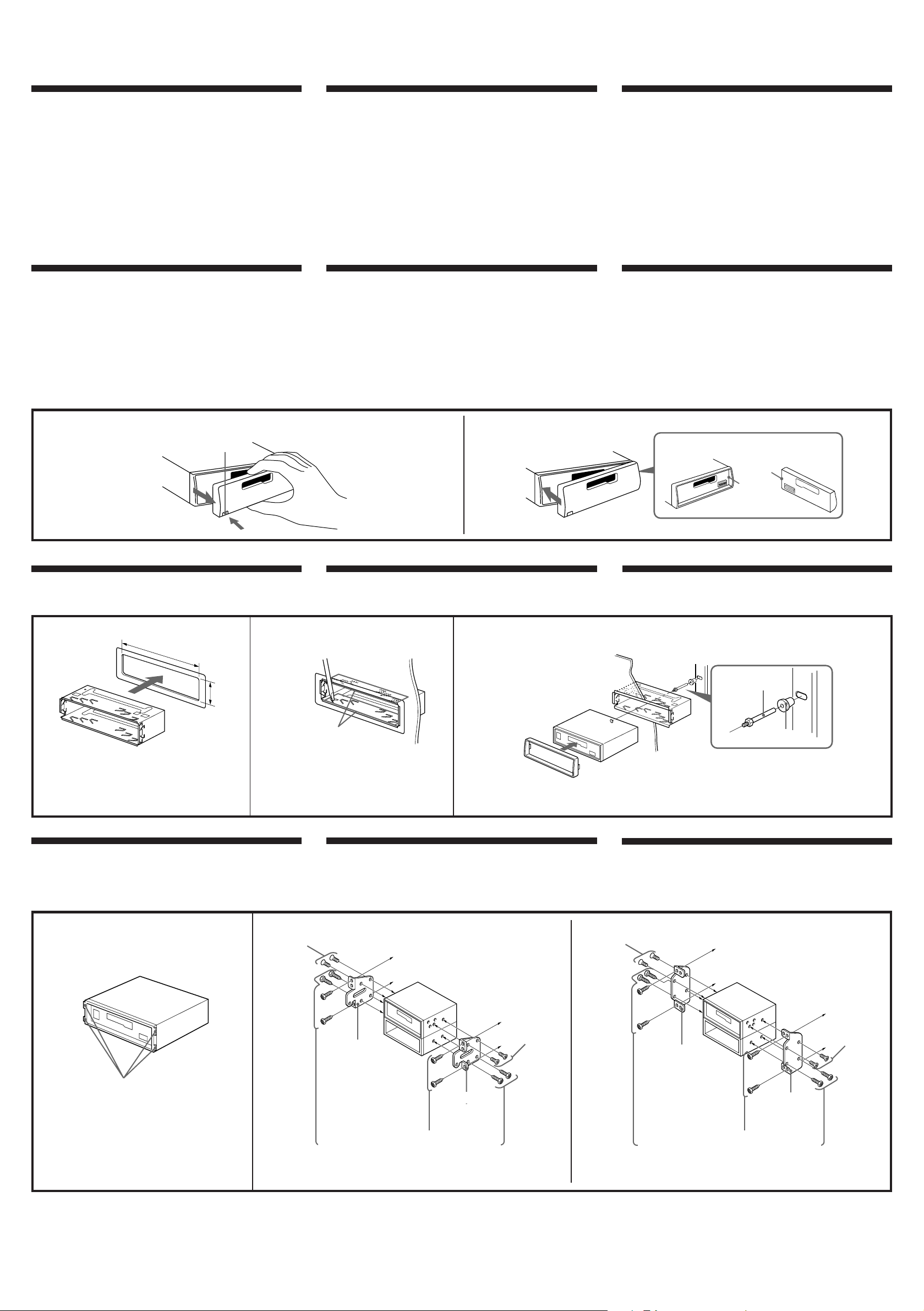
How to Detach and Attach the Front Panel
Before installing the unit, detach the front panel.
To detach
Press the (RELEASE) to detach the front panel then gently pull it out.
To attach
Align parts A and B, and push the front panel unit it clicks.
Precauciones
•No toque los cuatro orificios de la superficie superior de la unidad.
Estos orificios son para ajustes del sintonizador que solamente deberán
realizar técnicos de reparación.
•Elija cuidadosamente el lugar de montaje de forma que la unidad no
interfiera con la conducción.
•Evite instalar la unidad donde pueda quedar sometida a altas
temperaturas, como a la luz solar directa o al aire caliente de
calefacción, o a polvo, suciedad, o vibraciones excesivas.
•Para realizar una instalación segura y firme, emplee solamente la
ferretería de montaje suministrada.
Ajuste del ángulo de montaje
Ajuste el ángulo de montaje a menos de 20°.
Forma de extraer e instalar el panel frontal
Antes de instalar la unidad, extraiga el panel frontal.
Para extraerlo
Presione la tecla (RELEASE) para extraer el panel frontal y, a
continuación, tire de él hacìa fuera con suavidad.
Para instalarlo
Alinee las partes A y B, y presione el panel frontal hasta que chasquee.
®œ•Œ´e ™æ® µ
• –§ æ’¶¤ƒ •ªæ˜ ª °™ •| ”§p§’-B ”§’•u®—±M ~§H ˚ ’æ„ ’ø”æ˜Æ…§ß•Œ -
• •ªæ˜ –©Ò¶b§£ß´ ™•qæ˜æræp§ß B-
• ¡ ßKß‚•ªæ˜©Ò¶b ™ §ß B°M¶p ß•˙™ ±µ ”Æg°N xÆ æ˜´e°N©Œ¶« – •¶h°N º
¿Ú©ˆ®¸æ_ µ•¶a§Ë-
• ¨ §F¶w•˛ _®£°M¶w ÀÆ… –®œ•Œ™˛ƒ›™ ¶w À s•Û -
¶w À®§´ §ß ’æ„
–¶b20´ •H§ ’愶w À®§´ -
´e™O§ß À®¯
}©l¶w À•H´e°M –•˝©Ó§U´e™O /B
n©Ó®¯Æ…
´ˆ§U (RELEASE)°]ƒ¿©Ò°^´ˆ s•H±» }´e ±™O°MµM´·ª¥ª¥¶aß‚•¶®˙§U -
n¶w ÀÆ…
¶p œ©“•‹°M Ô «¶Ï m A ©M B °MµM´·±N•™ º¶V§ ¿£§J°M™ •®Ï•d‹÷¡n T -
To detach
Para extraerlo
n©Ó®¯Æ…
Mounting example
Installation in the dashboard
1
1
182 mm
(RELEASE)
53 mm
Ejemplo de montaje
Instalación en el salpicadero
2
Bend these claws for a tight fit,
if necessary.
Si es necesario, doble estas uñas.
¶p¶ • n°MßÈ s o®«§p¡l•H®D Ú K
™Àt/
To attach
Para instalarlo
n¶w ÀÆ…
3
5
Dashboard
Salpicadero
ªˆ™Ì™O
¶w À®“§l
¶w À©Ûªˆ™Ì™O§W
First attach 5 to the unit, then insert
the unit into 1.
En primer lugar, fije 5 a la unidad y, a
continuación, inserte ésta en 1.
±N 5 À¶b昮 °MµM´·±N昮 ¥°§J 1/
Fire wall
Panel cortafuegos
®æ§ıæ¿
1
A
B
2
3
Mounting the Unit in a Japanese Car
You may not be able to install this unit in some makes of Japanese cars. In
such a case, consult your Sony dealer.
1
With nippers or similar, cut off the claws
on both side of the unit.
Con unas tenazas o una herramienta
similar, corte los ganchos de ambos lados
de la unidad.
–ßQ•Œ X§l©Œ ˛¶¸§u®„±N昮 ®‚ º™ §p¡lßÈ
±º/
2 TOYOTA
4
max. size
M5 × 8mm
Tamaño
máx.
M5 × 8mm
çj§ÿ§o
5 × 8 mm
Montaje de la unidad en un automóvil
japonés
Usted no podrá instalar esta unidad en algunos automóviles japoneses.
En tal caso, consulte a su proveedor Sony.
to dashboard/center console
al salpicadero/consola central
¶‹ªˆ™Ì™O°˛§§•°±±®Ó c
4
max. size
M5 × 8mm
Tamaño
máx.
M5 × 8mm
çj§ÿ§o
5 × 8 mm
Bracket
Soporte
§‰¨[
Bracket
Soporte
§‰¨[
Existing parts supplied with your car
Piezas existentes suministradas con su automóvil
¶w ÀÆ…°M –®œ•Œ™˛ƒ›©Û®T®Æ™ ¶U ÿ s•Û /
NISSAN
4
max. size
M5 × 8mm
Tamaño
máx.
M5 × 8mm
çj§ÿ§o
5 × 8 mm
n¶w À©Û§È•ª®T®Æ Ã
¶ ™ ®T®Æ§£Ø‡¶w À•ªæ˜°M¶ Æ…°M –¶V¬˜ Q¶a Ùҙ Sony gæP©±¨d fl-B
to dashboard/center console
al salpicadero/consola central
¶‹ªˆ™Ì™O°˛§§•°±±®Ó c
4
max. size
M5 × 8mm
Tamaño
máx.
M5 × 8mm
çj§ÿ§o
5 × 8 mm
Bracket
Soporte
§‰¨[
Bracket
Soporte
§‰¨[
Existing parts supplied with your car
Piezas existentes suministradas con su automóvil
¶w ÀÆ…°M –®œ•Œ™˛ƒ›©Û®T®Æ™ ¶U ÿ s•Û /
Note
To prevent malfunction, install only with the supplied screws 4.
Nota
Para evitar que se produzcan fallos, realice la instalación solamente con los tornillos
suministrados 4.
µ˘
¨ ®æ§Óµo•Õ N•~® ¨G°M¶w ÀÆ…•u؇®œ•Œ™˛ƒ›™¡µ
4
-
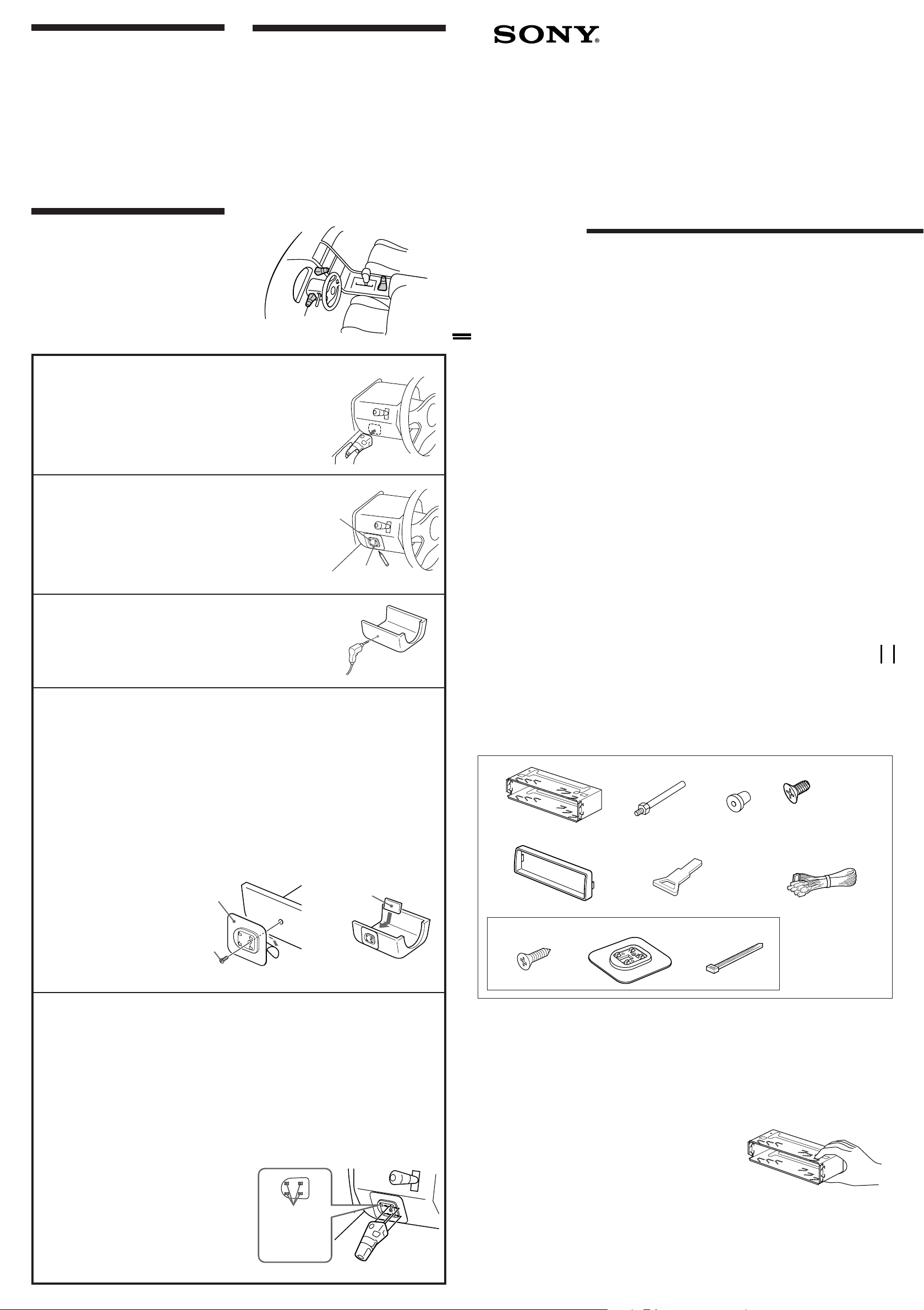
Installing the rotary commander
(XR-C5090 only)
Notes
• Choose the mounting location carefully so the rotary
commander will not interfere with operating the car.
• Do not install the rotary commander in a place where it may
jeopardize the safety of the (front) passenger in any way.
• When installing the rotary commander, be sure not to
damage any electrical cables etc. on the other side of the
mounting surface.
• Avoid installing the rotary commander where it may be
subject to high temperatures, such as from direct sunlight or
hot air from the heater etc.
¶w À±¤¬‡´¨ªª±±æ
( ©ÛXR-C5090)
µ˘
•
±¤¬‡´¨ªª±±æ – À¶b§£ß´ ™®T®Ææræp§ß B -
•
§£•iß‚±¤¬‡´¨ªª±±æ À¶b Ô º´»¶ ¶M¿I™ ¶a§Ë-
•
¶w Àªª±±æ Æ…°M –™` N§£ n ˝¡ µ v À§Œ¶w À ±§œ ±™
q uµ•-
•
¡ ßKß‚ªª±±æ ¶w À¶b ™ °M¶p™ Æg ß•˙© §U©Œ®¸ xÆ æ˜
ºˆ¨yßj¿ª™ ¶a§Ë-
Instalación del mando rotativo
(XR-C5090 solamente)
Notas
• Elija cuidadosamente el lugar de montaje de forma que el
mando rotativo no dificulte la conducción del coche.
• No instale el mando rotativo en un lugar donde pueda poner
en peligro la seguridad del pasajero acompañante.
• Al instalar el mando rotativo, asegúrese de no dañar los
cables de electricidad, etc., del otro lado de la superficie de
montaje.
• Procure no instalar el mando rotativo en un lugar expuesto
a altas temperaturas, como a la luz solar directa o al aire
caliente de la calefacción, etc.
Example of a mounting location
Ejemplo de un lugar de montaje
¶w À®“§l
3-861-692-21 (1)
FM/AM
Cassette Car
Stereo
Installation/Connections
Instalación/Conexiones
¶w À°˛ u Ù§ß s±µ
Choose the exact location for mounting the rotary commander, then
clean the mounting surface.
1
Dirt and oil impair the adhesive strength of the double-sided adhesive tape.
Una vez elegido el lugar de montaje del mando rotativo, limpie
previamente la superficie de montaje.
La suciedad o la grasa dañan la intensidad adhesiva de la cinta adhesiva de dos caras.
øÔ拧@ ”æA¶X¶w À±¤¬‡´¨ªª±±æ ™ ¶a§Ë°MµM´· Mº‰¶w À ±/
™Ì ±ªÍ º©Œ¶ ™o¶ |¥ÓßC®‚ ± ¶±a™ ¬H K§O-
Mark the position for the supplied screw.
Use the screw holes on the mounting hardware 9 to mark the position.
2
Marque la posición para el tornillo suministrados.
Para ello, utilice los orificios para tornillos de la ferretería de montaje 9.
µe 1 ”®—¡ µ v p§’§ß B /
´ˆ ”¶w À s•Û 9™ ¡ µ v§’¶Ï mß@ O -
Remove the steering wheel column cover, and drill 2 mm diameter hole
at the marked position.
3
Extraiga la cubierta de la columna de la dirección y haga un orificio de 2
mm. de diámetro en el lugar marcado.
®˙§U¬‡¶V¨W•~¥fl°M® ¶b©“ß@ O §ßBp} 2mm §j§p™ v§’/
Warm the mounting surface and the double-sided adhesive tape on the mounting hardware
9 to a temperature of 20°C to 30°C, and attach the mounting hardware to the mounting
4
surface applying even pressure. Use the supplied screw 8 to set into secure position.
Attach a piece of heavy duty tape etc. on the other side of the mounting surface to cover the protruding tips of the
screws so they will not interfere with any electrical cables etc. inside the steering wheel column.
Caliente la superficie de montaje y la cinta adhesiva de doble cara de la ferretería de montaje
9 a una temperatura entre 20°C y 30°C, y ajuste la ferretería de montaje a la superficie de
montaje ejerciendo una presión uniforme. A continuación, apriete el tornillo 8 suministrado.
Adhiera un trozo de cinta adhesiva resistente, etc. en el otro lado de la superficie de montaje para cubrir los extremos
de los tornillos que sobresalgan, de forma que no interfieran con los cables de electricidad, etc., del interior de la
columna de dirección.
ß‚¶w À ±§Œ¶w À s•Û 9™ ®‚ ± ¶±a•[ºˆ¶‹ 20¢X®Ï 30¢Xµ{´ °MµM´·ß‚¶w À s•Û K¶b¬‡¶V¨W•~¥fl°M KÆ…
©“¨I•[¿£§O ß°µ•/B•H™˛ƒ›™ ¡ µ v 8 ß‚¶w À s•Û v Ú/
¶b¶w À ±™ §œ ±§ß¡ µ v¶y › °§¿°M K±i±j§O ¶±aµ•°M•HßK ÀÆ`¬‡¶V¨W à ±™ q uµ•-
9
Mark
Marca
O
XR-C5090
XR-4790
Sony Corporation 1998
Parts for Installation and Connections
Componentes de montaje y conexiones
¶w À§Œ u Ù s±µ•Œ™ s•Û
The numbers in the list correspond to those in the instructions.
Los números de la lista corresponden a los de las instrucciones.
§U ± œ™Ì Ù X©Mª°©˙§Â§§™ X¨¤¶P -
1
5
2
× 1 × 1 × 1
6
3
4
× 5
(incl. 1 reserve)
(se incluye 1 de reserva)
(•]¨A1 ”®— •Œ™¡µ)
7
Cut the mounting hardware 9, If necessary.
Si es necesario, corte la pieza 9.
• nÆ…°M•i I§¡¶w À§ ™˜ 9/B
After reinstalling the steering wheel column cover, attach the rotary commander to the
mounting hardware by aligning the four holes on the bottom of the rotary commander with
5
the four catches on the mounting hardware and sliding the rotary commander until it locks
into place as illustrated.
Note
If you are mounting the rotary commander on the steering wheel column, make sure that the protruding tips of the
screws on the inner surface of the column do not in any way hinder or interfere with the movement of the rotating
shaft, operative parts of the switches or the electrical cables etc. inside the column.
Una vez instalada la cubierta de la columna de dirección, fije el mando rotativo a la ferretería
de montaje alineando los cuatro orificios de la parte inferior del mando con los cuatro
enganches de la ferretería de montaje. A continuación, deslice el mando hasta que encaje en
su sitio como se muestra en la ilustración.
Nota
Si monta el mando rotativo en la columna de dirección, asegúrese de que los extremos de los tornillos que sobresalgan de
la superficie interior de la columna no dificulten el movimiento del eje de rotación ni los componentes operativos de los
conmutadores o los cables de electricidad, etc., del interior de la columna.
¶b¬‡¶V¨W•~¥fl ´ s À§W•H´·°Mß‚ªª±±æ À¶b¶w À
s•Û à /B ÀÆ… –ß‚ªª±±æ © °™ 4 ”§p§’ Ô «¶w À
s•Û™ 4 ”§p _°MµM´·´ˆ ”¥° œ©“•‹°Mß‚ªª±±æ ¥°
§J s•Û Ã/
µ˘
¶bß‚ªª±±æ À¶b¬‡¶V¨W•~¥flÆ…°M• ™` N¬‡¶V¨W Ù
¡ µ v§ß¶y ›°M§£•i®Î®Ï©Œ ÀÆ`®Ï¬‡¶V¨W¥fl à ±™ ¬‡
b°N } ˆ™ æfiß@ °§¿©Œ q uµ•-
9
8
Heavy duty tape etc.
Cinta adhesiva resistente, etc.
±j§O ¶±aµ•
Holes
Orificios
§p§’
9!º8
× 1
XR-C5090 only
XR-C5090 solamente
× 1× 1
( ©ÛXR-C5090)
× 1 × 1
The release key 6 is used for dismounting the unit. See the Operating Instructions manual for details.
La llave de liberación 6 se utiliza para desmontar la unidad. Con respecto a los detalles, consulte el manual de
instrucciones.
Y nß‚•ªæ˜•—©T©w§ß B©Ó®¯§U®”°M –®œ•Œ P }•Œ™ _ Õ6-B ‘ ” –¨›®œ•Œª°©˙Æ— -
× 1
Caution
Cautionary notice for handling the bracket 1. Handle the
bracket carefully to avoid injuring your fingers.
Precaución
Advertencia sobre la manipulación del soporte 1. Tenga
mucho cuidado al manipular el soporte para evitar posibles
lesiones en los dedos.
™` N
æ À®¯§‰¨[ 1 Æ…°M –ØSßO™` NßO À®Ï§‚´¸ -
 Loading...