

Sony XR-2750 Service manual
XR-2750/2753
SERVICE MANUAL
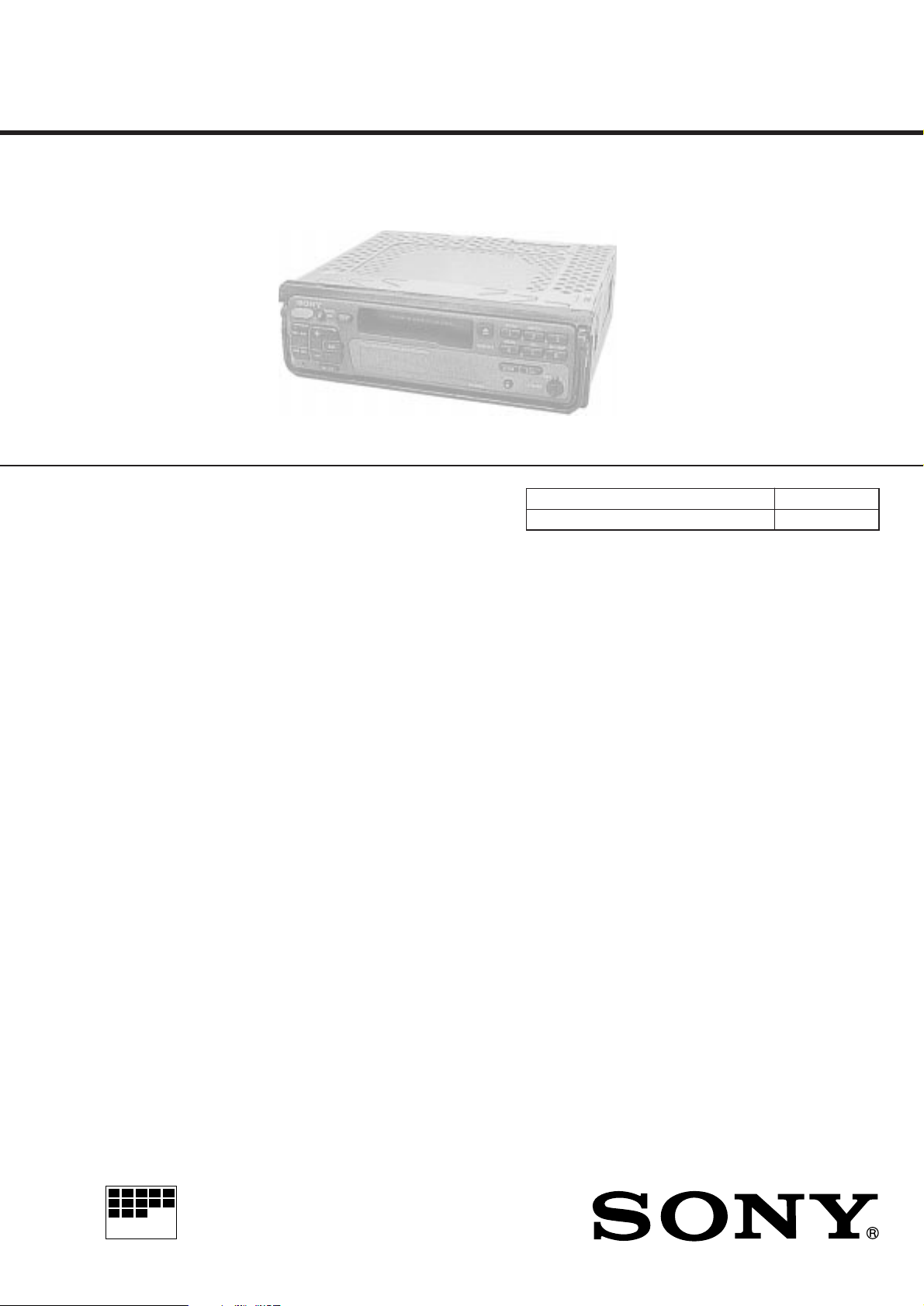
Photo: XR-2753
AEP Model
UK Model
XR-2750
East European Model
XR-2753
Model Name Using Similar Mechanism XR-3750/C553SP
T ape Transport Mechanism T ype
MG-52A-135
Cassette player section
Tape track 4-track 2-chanel stereo
Wow and flutter 0.08% (WRMS)
Frequency response 30 – 20,000 Hz
Signal-to-noise ratio 58 dB
Tuner section
FM
*
Tuning range XR-2750:
Antenna terminal External antenna connector
Intermediate frequency 10.7 MHz
Usable sensitivity 8 dBf
Selectivity 75 dB at 400 kHz
Signal-to-noise ratio 65 dB (stereo),
Harmonic distortion at 1 kHz
Separation 35 dB at 1 kHz
Frequency response 30 – 15,000 Hz
Capture ratio 2 dB
* There are the numerical values measured at 87.5 – 108.0 MHz
MW/LW
Tuning range MW: 531 – 1,602 kHz
Antenna terminal External antenna connector
Intermediate frequency 10.71 MHz/450 kHz
Sensitivity MW: 30 µV
87.5 – 108.0 MHz
XR-2753:
65.0 – 74.0 MHz (at 30 kHz step)
87.5 – 108.0 MHz (at 50 kHz step)
68 dB (mono)
0.5% (stereo),
0.3% (mono)
LW : 153 – 281 kHz
LW: 50 µV
SPECIFICATIONS
Power amplifier section
Outputs Speaker outputs (sure seal connectors)
Speaker impedance 4 – 8 ohms
Maximum power output 35 W × 4 (at 4 ohms)
General
Outputs Power antenna control lead
Tone controls Bass ±8 dB at 100 Hz
Treble ±8 dB at 10 kHz
Power requirements 12 V DC car battery (negative ground)
Dimensions Approx. 188 × 58 × 183 mm (w/h/d)
Mounting dimensions Approx. 182 × 53 × 164 mm (w/h/d)
Mass Approx. 1.6 kg
Supplied accessories Parts for installation and connections (1 set)
Design and specifications are subject to change without notice.
MICROFILM
FM/MW/LW CASSETTE CAR STEREO
TABLE OF CONTENTS
SERVICING NOTES
1. GENERAL
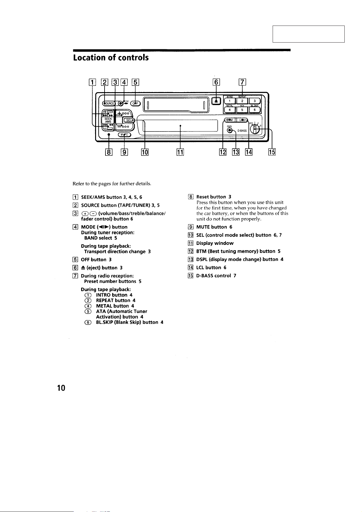
Location of Controls ........................................................ 3
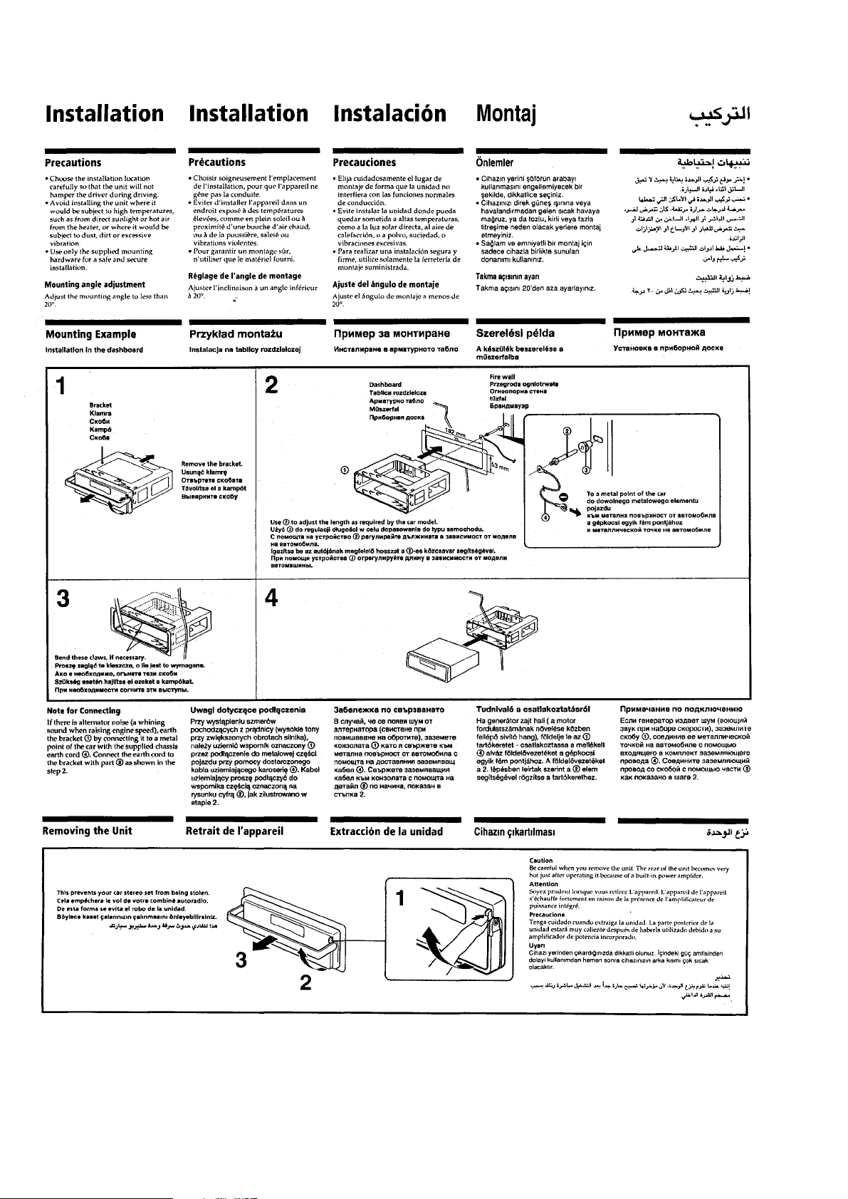
Installation ....................................................................... 4
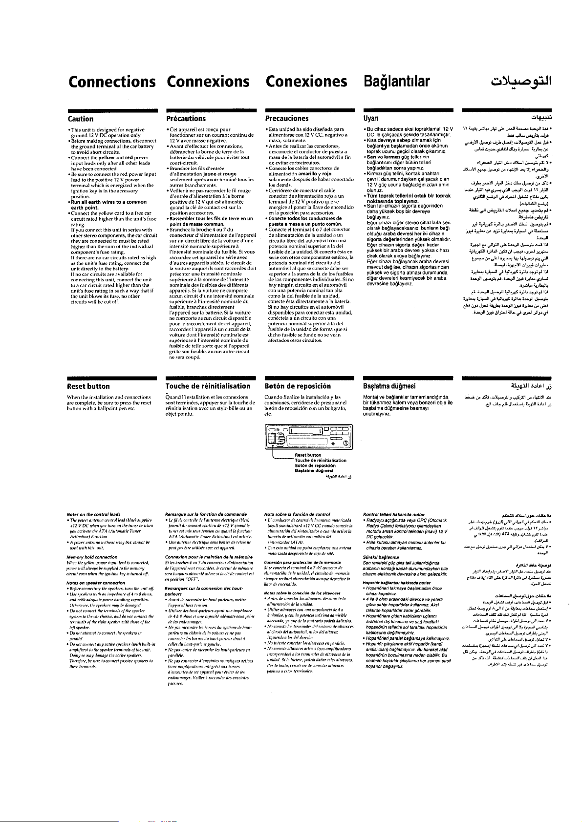
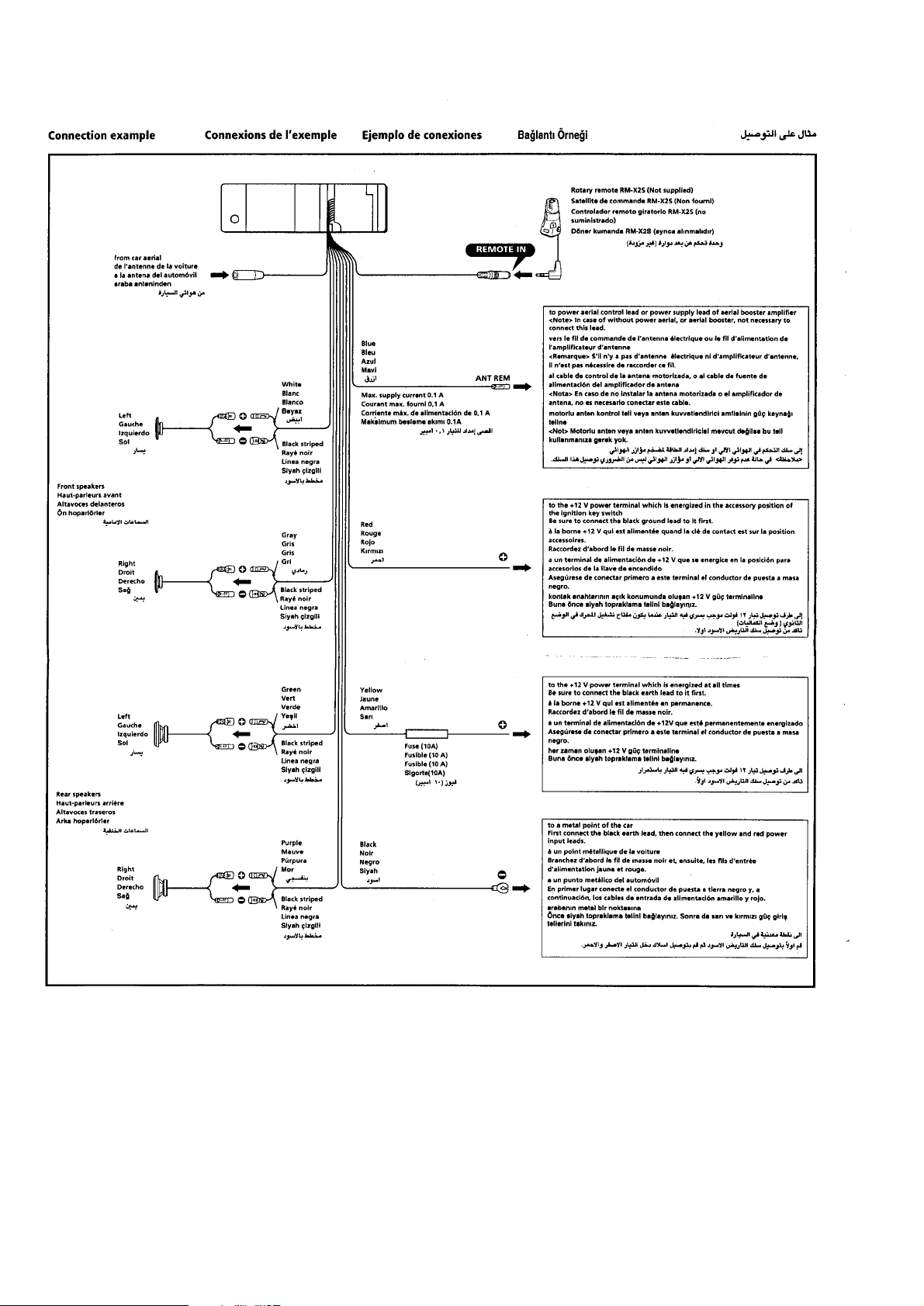
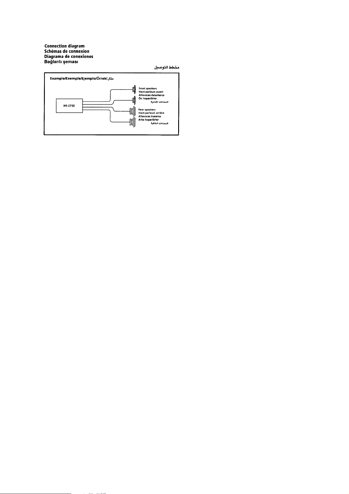
Connections ..................................................................... 5
2. DISASSEMBLY.......................................................... 8
3. ASSEMBLY OF MECHANISM DECK ........... 11
4. MECHANICAL ADJUSTMENTS ....................... 17
5. ELECTRICAL ADJUSTMENTS
Test Mode ........................................................................ 17
Tape Deck Section ........................................................... 18
Tuner Section................................................................... 18
6. DIAGRAMS
6-1. IC Pin Function Description ............................................ 21
6-2. Printed Wiring Boards –MAIN Section– ........................ 23
6-3. Schematic Diagram –MAIN Section– ............................ 27
6-4. Printed Wiring Board –CONTROL Section–................. 32
6-5. Schematic Diagram –CONTROL Section–.................... 34
7. EXPLODED VIEWS ................................................ 39
8. ELECTRICAL PARTS LIST................................ 43
Flexible Circuit Board Repairing
• Keep the temperature of the soldering iron around 270 ˚C dur-
ing repairing.
• Do not touch the soldering iron on the same conductor of the
circuit board (within 3 times).
• Be careful not to apply force on the conductor when soldering
or unsoldering
Notes on chip component replacement
• Never reuse a disconnected chip component.
• Notice that the minus side of a tantalum capacitor may be dam-
aged by heat.
CAUTION
Danger of explosion if battery is incorrectly replaced.
Replace only with the same or equivalent type recommended by
the manufacturer.
Discard used batteries according to the manufacturer’ s instructions.
ADV ARSEL!
Lithiumbatteri-Eksplosionsfare ved fejlagtig håndtering.
Udskiftning må kun ske med batteri
af samme fabrikat og type.
Levér det brugte batteri tilbage til leverandøren.
ADVARSEL
Eksplosjonsfare ved feilaktig skifte av batteri.
Benytt samme batteritype eller en tilsvarende type
anbefalt av apparatfabrikanten.
Brukte batterier kasseres i henhold til fabrikantens
instruksjoner.
VARNING
Explosionsfara vid felaktigt batteribyte.
Använd samma batterityp eller en likvärdig typ som
rekommenderas av apparattillverkaren.
Kassera använt batteri enligt gällande föreskrifter.
VAROITUS
Paristo voi räjähtää, jos se on virheellisesti asennettu.
V aihda paristo ainoastaan laitev almistajan suosittelemaan tyyppiin.
Hävitä käytetty paristo valmistajan ohjeiden mukaisesti.
– 2 –
SECTION 1
GENERAL
This section is extracted
from instruction manual.
– 3 –
– 4 –
– 5 –
– 6 –
– 7 –
SECTION 2
DISASSEMBLY
Note: Follow the disassembly procedure in the numerical order given.
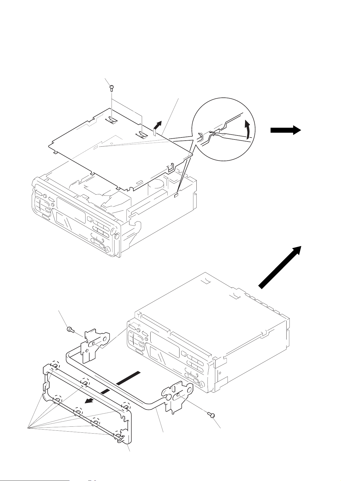
COVER
1
two screws
(PTT2.6 × 6)
A
3
Remove the cover to
ward direction A.
2
COLLAR (A), HANDLE ASS’Y
3
screw
(PTT2.6 × 6)
1
seven cla ws
4
handle ass’y
3
screw
(PTT2.6 × 6)
2
coller (A)
– 8 –
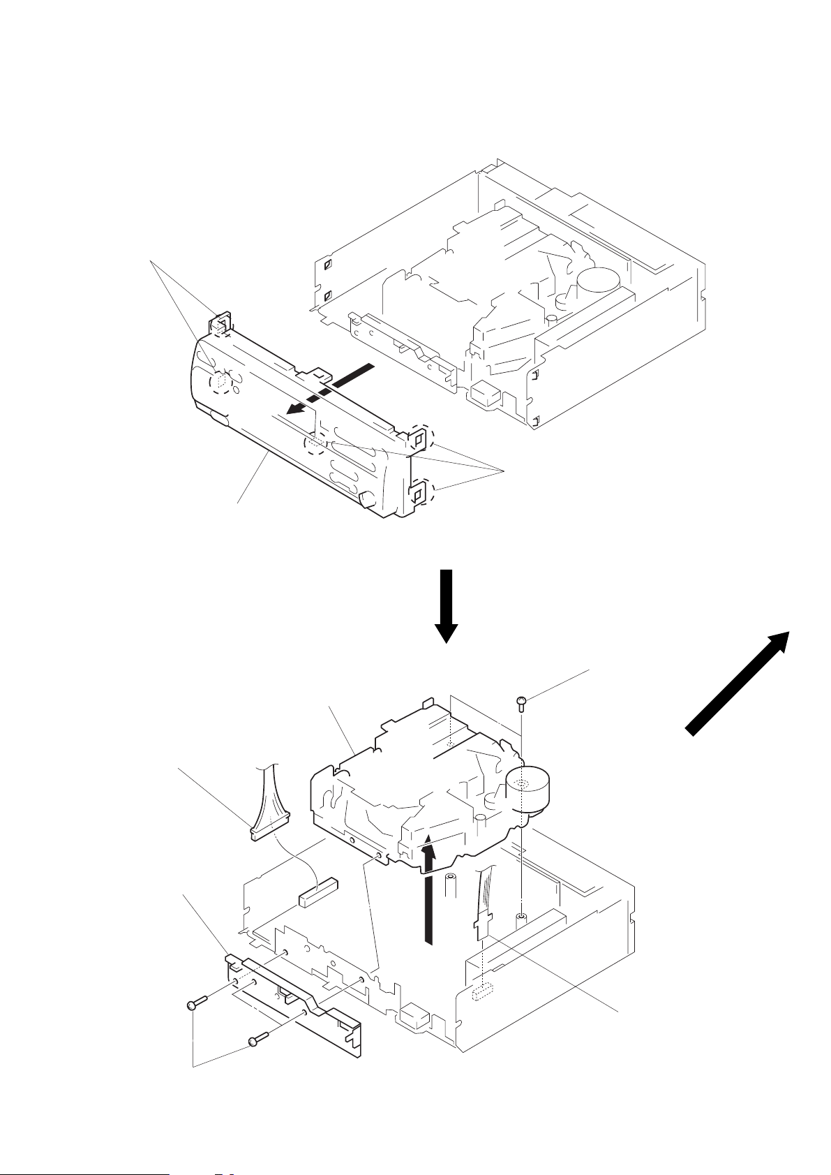
FRONT PANEL ASS’Y
1
two claws
1
three claws
2
front panel ass’y
MECHANISM DECK
1
connector
(CNP331)
4
front chassis
5
mechanism deck
3
two screws
(PTT2.6 × 6)
3
three screws
(PTT2.6 × 6)
– 9 –
2
flexible board
(CNP301)
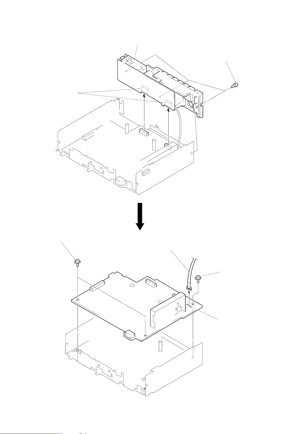
POWER BOARD
2
two connectors
(CNJ400, 401)
3
power board
1
three screws
(PTT2.6 × 8)
MAIN BOARD
1
two ground point
screws
4
antenna cable
2
ground point
screw
3
main board
– 10 –
SECTION 3
ASSEMBLY OF MECHANISM DECK
Note: Follow the assembly procedure in the numerical order given.
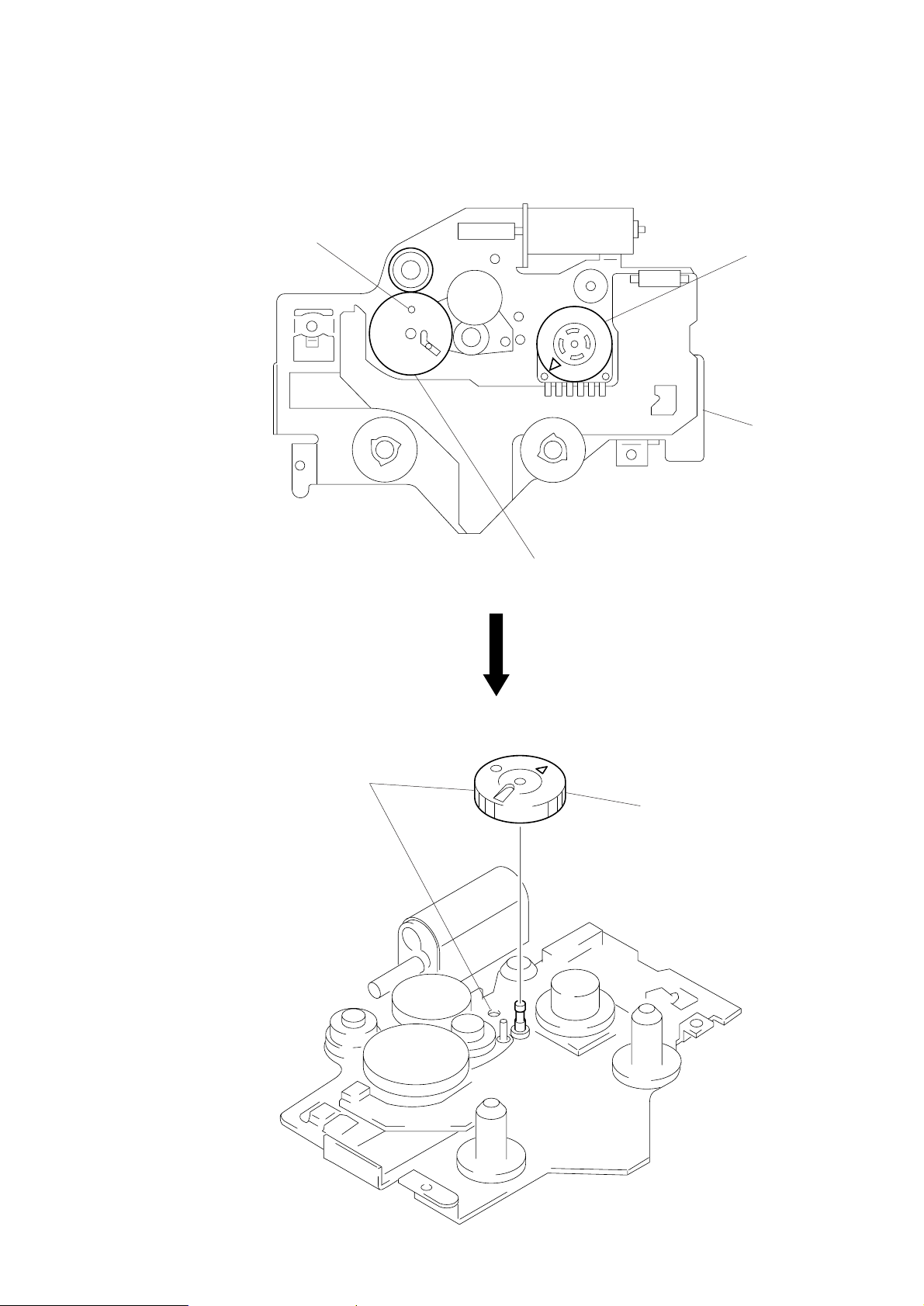
ALIGNMENT OF FRONT SWITCH
hole
1
Align ¢ mark on the rotary switch
the position shown in the figure.
chassis (S) ass’y
GEAR (LDGE)
1
Align hole as shown in the figure.
2
Align hole in the gear (LDG-D) with the
position shown in the figure.
2
Install the gear (LDG-E).
– 11 –
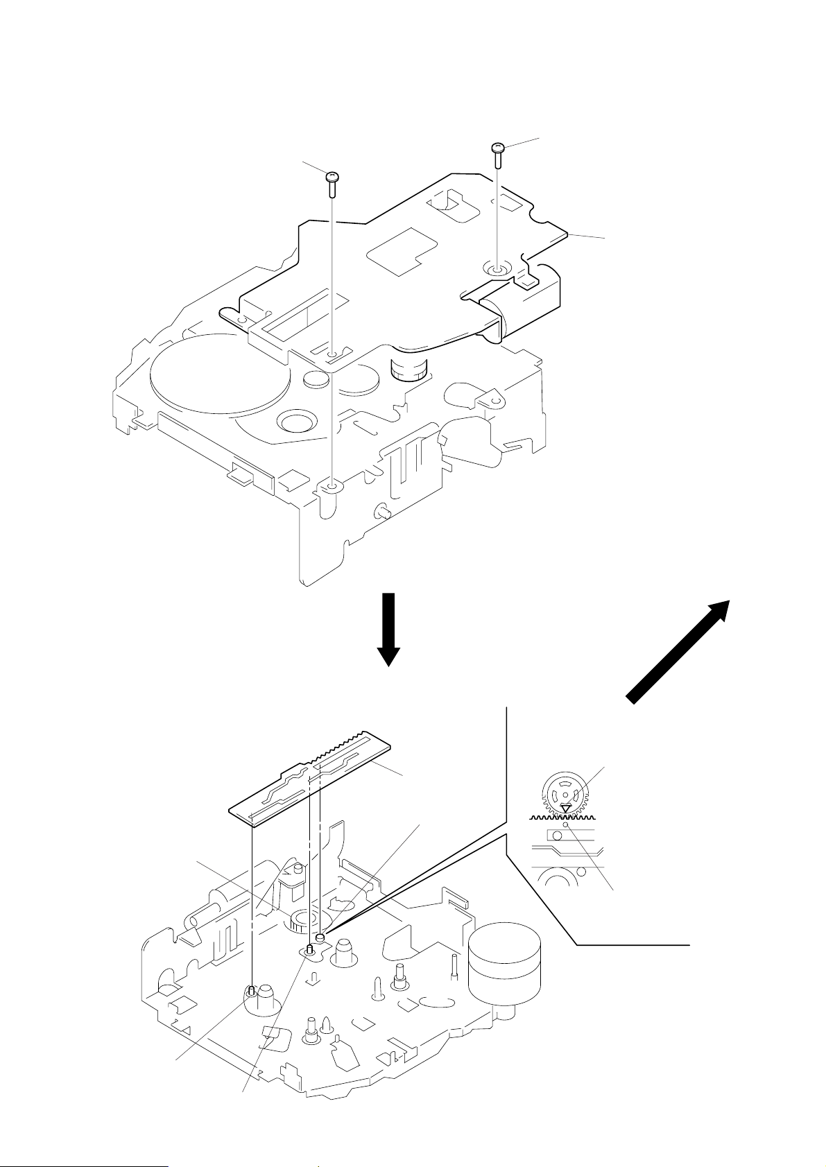
CHASSIS (S) ASS’Y
2
screw (PS2 × 4)
2
screw (PS2 × 4)
1
chassis (S) ass’y
LEVER (MODE)
1. Align ¢ mark on the rotary switch with
hole in the lever (mode).
2. Fit on positions A, B and C and install
the lever (mode).
rotary switch
lever (mode)
C
¢
mark on rotary switch
hole in lever (mode)
A
B
– 12 –
 Loading...