

SONY XR-1890 Service Manual
SERVICE MANUAL
SUPPLEMENT-1
File this supplement with the service manual.
Subject: Tuner unit Modification
XR-1890
US Model
(ENG-99004)
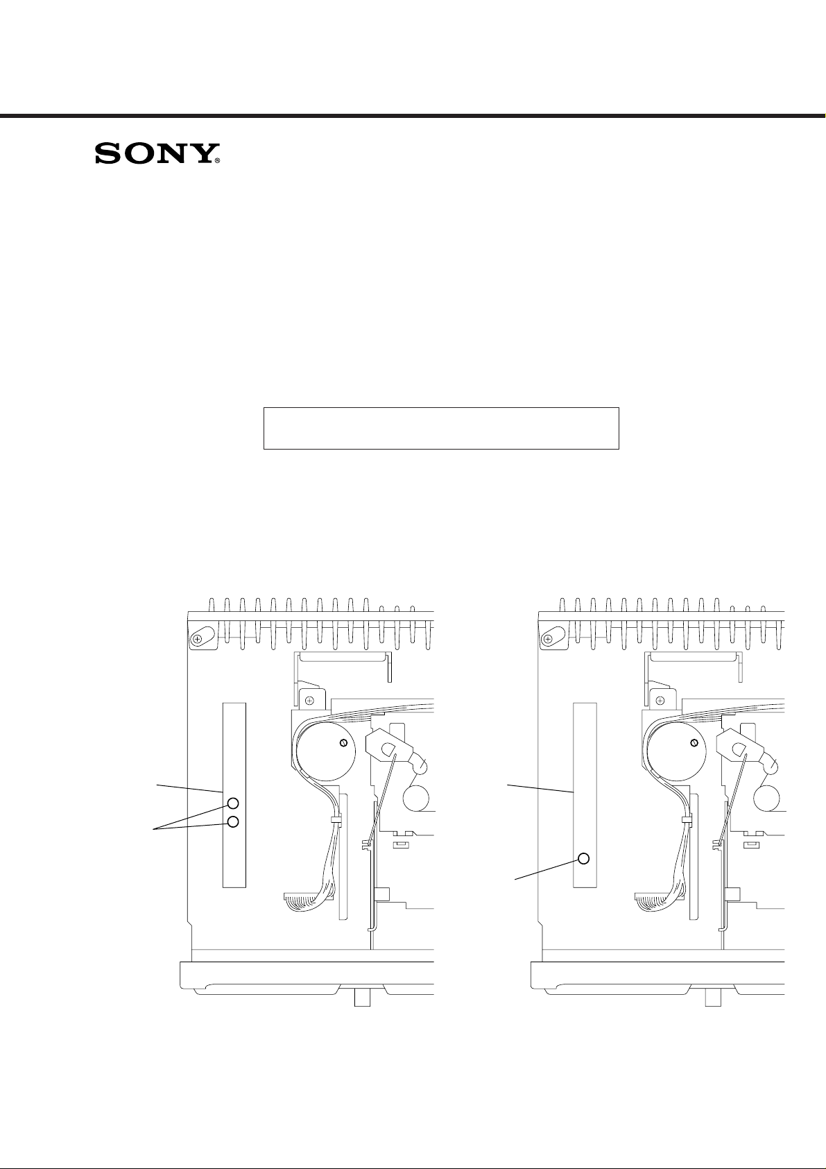
1. DISCRIMINATION
Former: New:
– SET UPPER VIEW –
TU100
Two
adjustment
holes
CN901
TU100
One
adjustment
hole
– SET UPPER VIEW –
CN901
2. ELECTRICAL ADJUSTMENTS
TUNER SECTION 0 dB=1 µV
AM section adjustment is done automatically in this set.
Cautions during repair
When the tuner unit is defective, replace it by a new one because its internal block is difficult to repair.
Note: Adjust the tuner section in the sequence shown below.
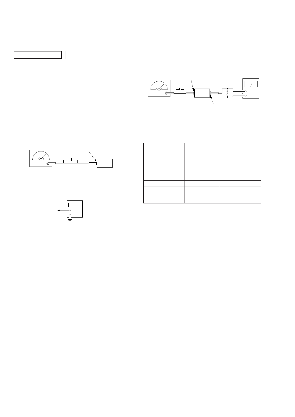
1. FM Auto Scan/Stop Level Adjustment
2. FM Stereo Separation Adjustment
FM Auto Scan/Stop Level Adjustment
Setting:
[TUNER] button: FM 1
FM RF signal
generator
Carrier frequency: 97.9 MHz
Output level: 22
Mode: mono
Modulation: 1 kHz, 22.5 kHz deviation (30%)
MAIN board
TP2 (SD)
±
Procedure:
1. Tune the set to 97.9 MHz.
2. Connect the digital voltmeter to TP2 (SD) on MAIN board.
3. Adjust RV1 on TU100 so that the reading on the digital voltmeter changes point from low to high.
antenna jack (CN900)
0.01 µF
5 dB
digital
voltmeter
+
–
set
FM Stereo Separation Adjustment
Setting:
[TUNER] button: FM1
FM RF signal
generator
Carrier frequency : 97.9 MHz
Output level : 74 dB
Mode : stereo
Modulation : main: 1 kHz, 33.75 kHz deviation (45%)
antenna jack (CN900)
0.01 µF
set
sub: 1 kHz, 33.75 kHz deviation (45%)
19 kHz pilot: 7.5 kHz deviation (10%)
4
speaker out terminal
Procedure:
FM Stereo
signal generator
output channel
L-CH L-CH A
R-CH L-CH Adjust RV2 on TU100
R-CH R-CH C
L-CH R-CH Adjust RV2 on TU100
Level meter Level meter
connection reading (dB)
for minimum reading.
for minimum reading.
L-CH Stereo separation: A-B
R-CH Stereo separation: C-D
The separations of both channels should be equal.
Specification: Separation more than 28 dB
Adjustment Location: See page 3.
level meter
Ω
B
D
+
–
Adjustment Location: See page 3.
– 2 –
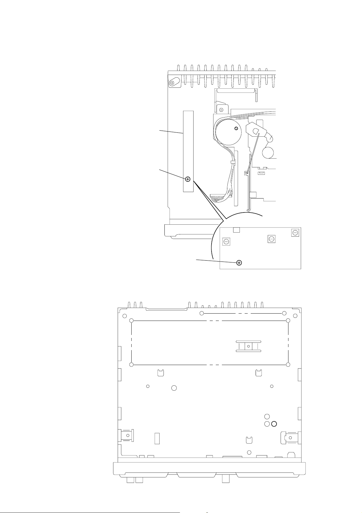
Adjustment Location:
RV1 FM Auto Scan/Stop Level Adjustment
– SET UPPER VIEW –
TU100
CN901
RV2 FM Stereo Separation Adjustment
– SET BOTTOM VIEW –
– TU100 (Component Side) –
– 3 –
TP2 (SD)
 Loading...