

Sony XR-1750 Service manual

SERVICE MANUAL
Ver 1.1 2001.04
XR-1750
US Model
E Model
Australian Model
Model Name Using Similar Mechanism NEW
T ape Transport Mechanism T ype
MG-52A-135
SPECIFICATIONS
AUDIO POWER SPECIFICATIONS (US model)
POWER OUTPUT AND TOTAL HARMONIC DISTORTION
13 watts per channel minimum continuous average power into 4 ohms, 4 channels driven from
20 Hz to 20 kHz with no more then 1% total harmonic distortion.
Cassette player section
Tape track 4-track 2-channel stereo
Wow and flutter 0.08% (WRMS)
Frequency response 30 – 20,000 Hz
Signal-to-noise ratio 58 dB
Tuner section
FM
Tuning range US model:
87.5 – 107.9 MHz
E, Australian model:
50 kHz/200 kHz switchable
87.5 – 108.0 MHz (at 50 kHz step)
87.5 – 107.9 MHz (at 200 kHz step)
Antenna terminal External antenna connector
Intermediate frequency 10.7 MHz
Usable sensitivity 8 dBf
Selectivity 75 dB at 400 kHz
Signal-to-noise ratio 65 dB (stereo), 68 dB (mono)
Harmonic distortion at 1 kHz
0.5% (stereo), 0.3% (mono)
Separation 35 dB at 1 kHz
Frequency response 30 – 15,000 Hz
Capture ratio 2 dB
Antenna terminal External antenna connector
Intermediate frequency 10.71 MHz/450 kHz
Sensitivity 30 µV
Power amplifier section
Outputs Speaker outputs (sure seal connectors)
Speaker impedance 4 – 8 ohms
Maximum power output 35 W × 4 (at 4 ohms)
General
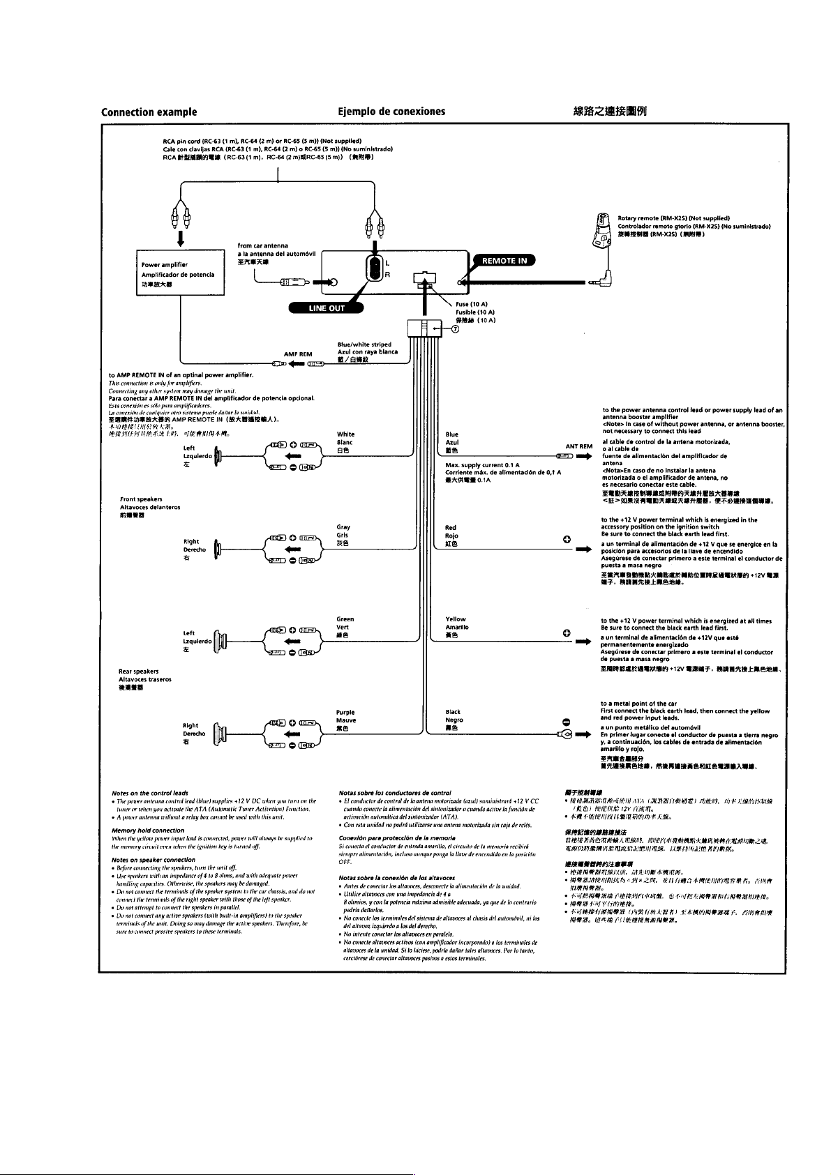
Outputs Power antenna control lead
Tone controls Bass ±8 dB at 100 Hz
Power requirements 12 V DC car battery (negative ground)
Dimensions Approx. 188 × 58 × 182 mm
Mounting dimensions Approx. 182 × 53 × 161 mm
Mass Approx. 1.2 kg (2 lb. 10 oz.)
Supplied accessories Parts for installation and connections (1 set)
Design and specifications are subject to change without notice.
Power amplifier control lead
Rear line out (1)
Treble ±8 dB at 10 kHz
(71/2 × 23/8 × 71/4 in.) (w/h/d)
(71/4 × 21/8 × 63/8 in.) (w/h/d)
AM
Tuning range US model:
530 – 1,710 kHz
E, Australian model:
9 kHz/10 kHz switchable
531 – 1,602 kHz (at 9 kHz step)
530 – 1,710 kHz (at 10 kHz step)
9-925-564-12 Sony Corporation
2001D0500-1 e Vehicle Company
C 2001.4 Shinagawa Tec Service Manual Production Group
FM/AM CASSETTE CAR STEREO

TABLE OF CONTENTS
SERVICING NOTES
1. GENERAL
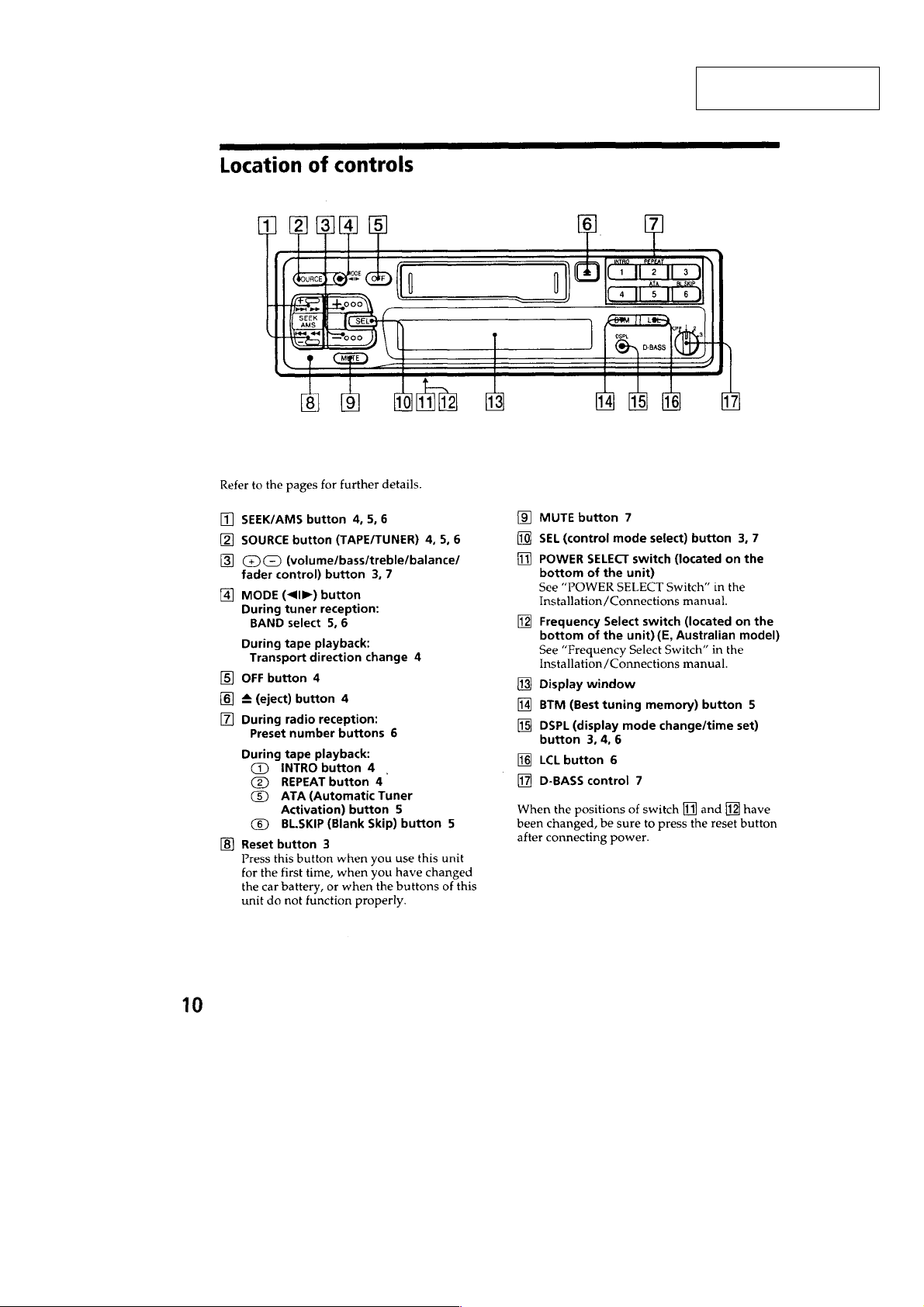
Location of Controls ........................................................ 3
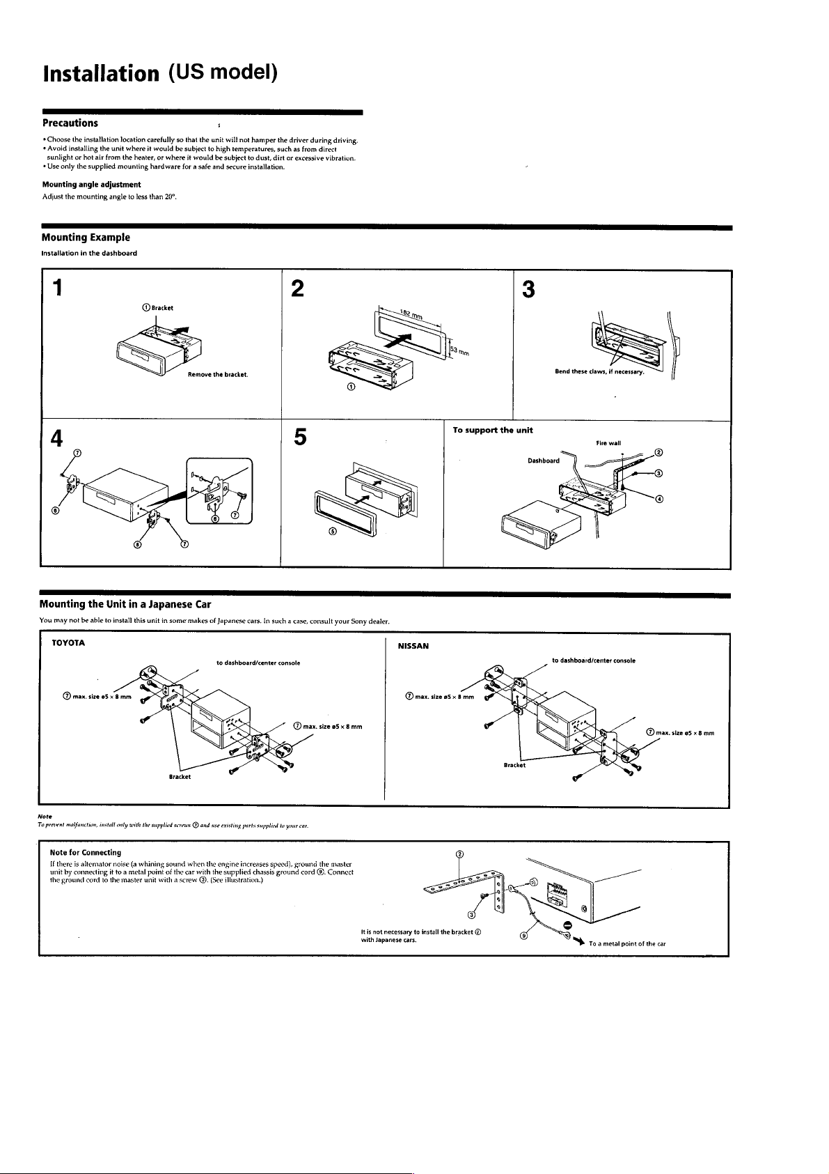
Installation (US Model) ................................................... 4
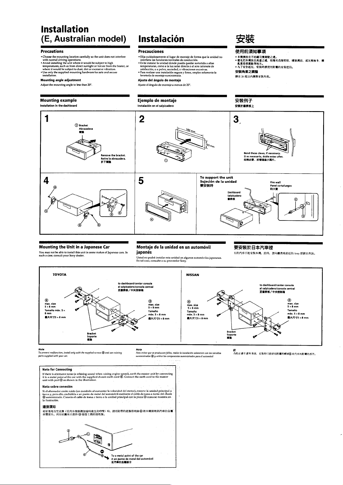
Installation (E, Australian Model) ................................... 5
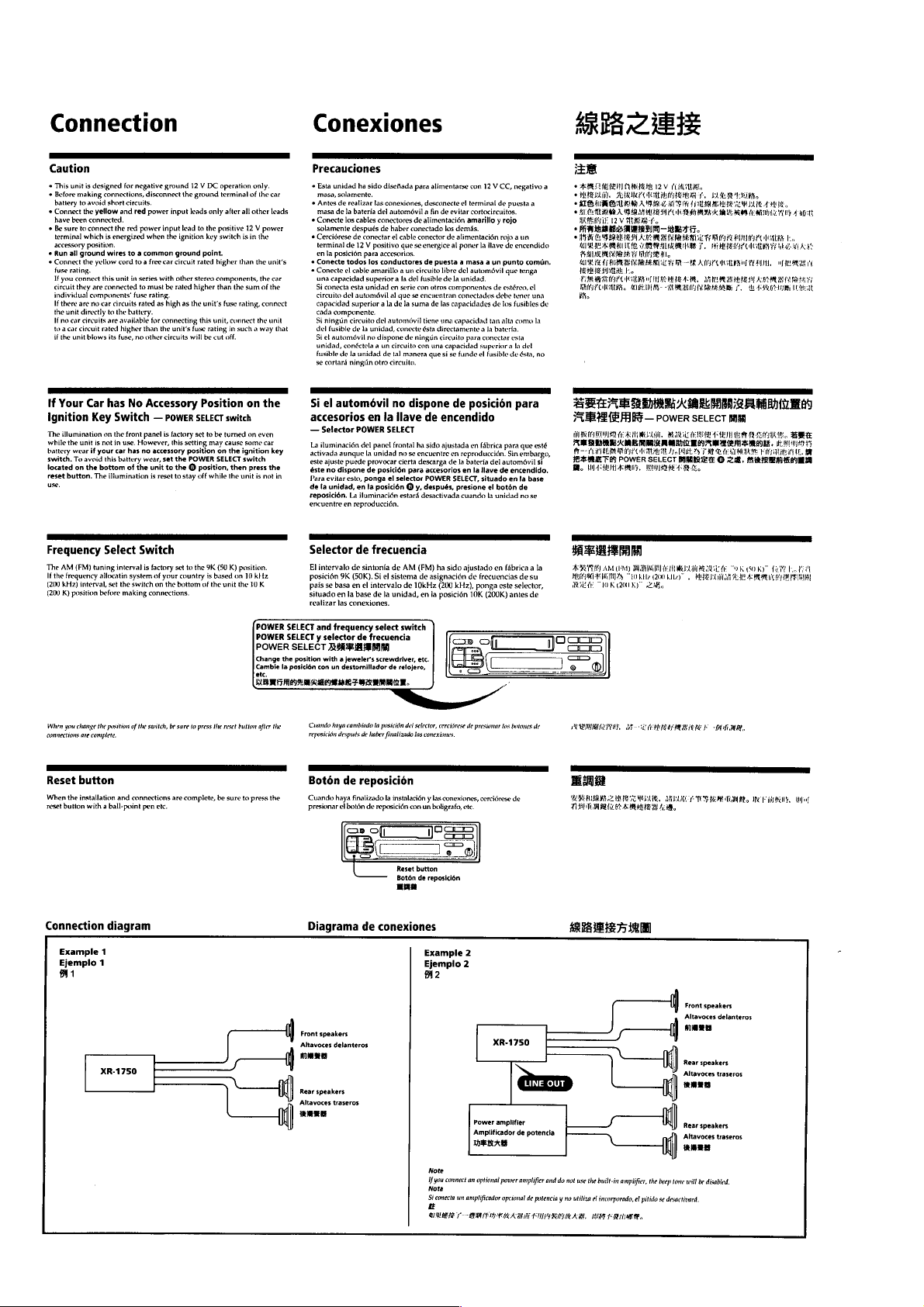
Connection....................................................................... 6
2. DISASSEMBLY.......................................................... 8
3. ASSEMBLY OF MECHANISM DECK ........... 10
4. MECHANICAL ADJUSTMENTS ....................... 16
5. ELECTRICAL ADJUSTMENTS
Tape Deck Section ........................................................... 16
Tuner Section................................................................... 16
6. DIAGRAMS
6-1. IC Pin Function Description ............................................ 18
6-2. Printed Wiring Boards –MAIN Section– ........................ 20
6-3. Schematic Diagram –MAIN Section– ............................ 23
6-4. Printed Wiring Board –CONTROL Section– ................. 27
6-5. Schematic Diagram –CONTROL Section–.................... 29
7. EXPLODED VIEWS ................................................ 33
8. ELECTRICAL PARTS LIST................................ 37
Flexible Circuit Board Repairing
• Keep the temperature of the soldering iron around 270 ˚C dur-
ing repairing.
• Do not touch the soldering iron on the same conductor of the
circuit board (within 3 times).
• Be careful not to apply force on the conductor when soldering
or unsoldering
Notes on chip component replacement
• Never reuse a disconnected chip component.
• Notice that the minus side of a tantalum capacitor may be dam-
aged by heat.
– 2 –
SECTION 1
GENERAL
This section is extracted
from instruction manual.
– 3 –
– 4 –
– 5 –
– 6 –
– 7 –
SECTION 2
DISASSEMBLY
Note: Follow the disassembly procedure in the numerical order given.
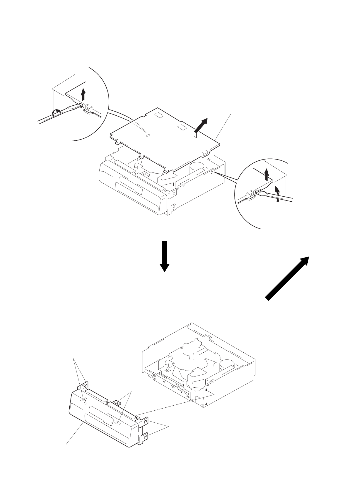
COVER
2
1
FRONT PANEL ASS’Y
A
3
Remove the cover
to direction of the arrow A.
2
1
1
two claws
2
front panel ass’y
1
two claws
– 8 –
1
two claws
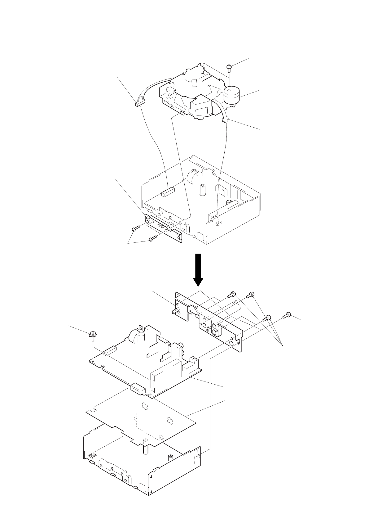
MECHANISM DECK
1
connector
(CN351)
4
front chassis
3
two screws
(PTT2.6 × 6)
5
2
mechanism deck
flexible flat cable
(CN1)
3
three screws
(PTT2.6 × 6)
MAIN BOARD, HEAT SINK
2
two ground point
screws
6
heat sink
3
main board
4
insulator
5
seven screws
(PTT2.6 × 10)
1
three screws
(PTT2.6 × 10)
– 9 –
SECTION 3
ASSEMBLY OF MECHANISM DECK
Note: Follow the assembly procedure in the numerical order given.
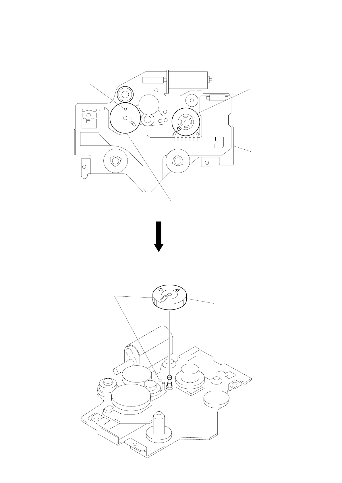
ALIGNMENT OF FRONT SWITCH
hole
1
Align ¢ mark on the rotary switch
the position shown in the figure.
chassis (S) ass’y
GEAR (LDGE)
1
Align hole as shown in the figure.
2
Align hole in the gear (LDG-D) with the
position shown in the figure.
2
Install the gear (LDG-E).
– 10 –
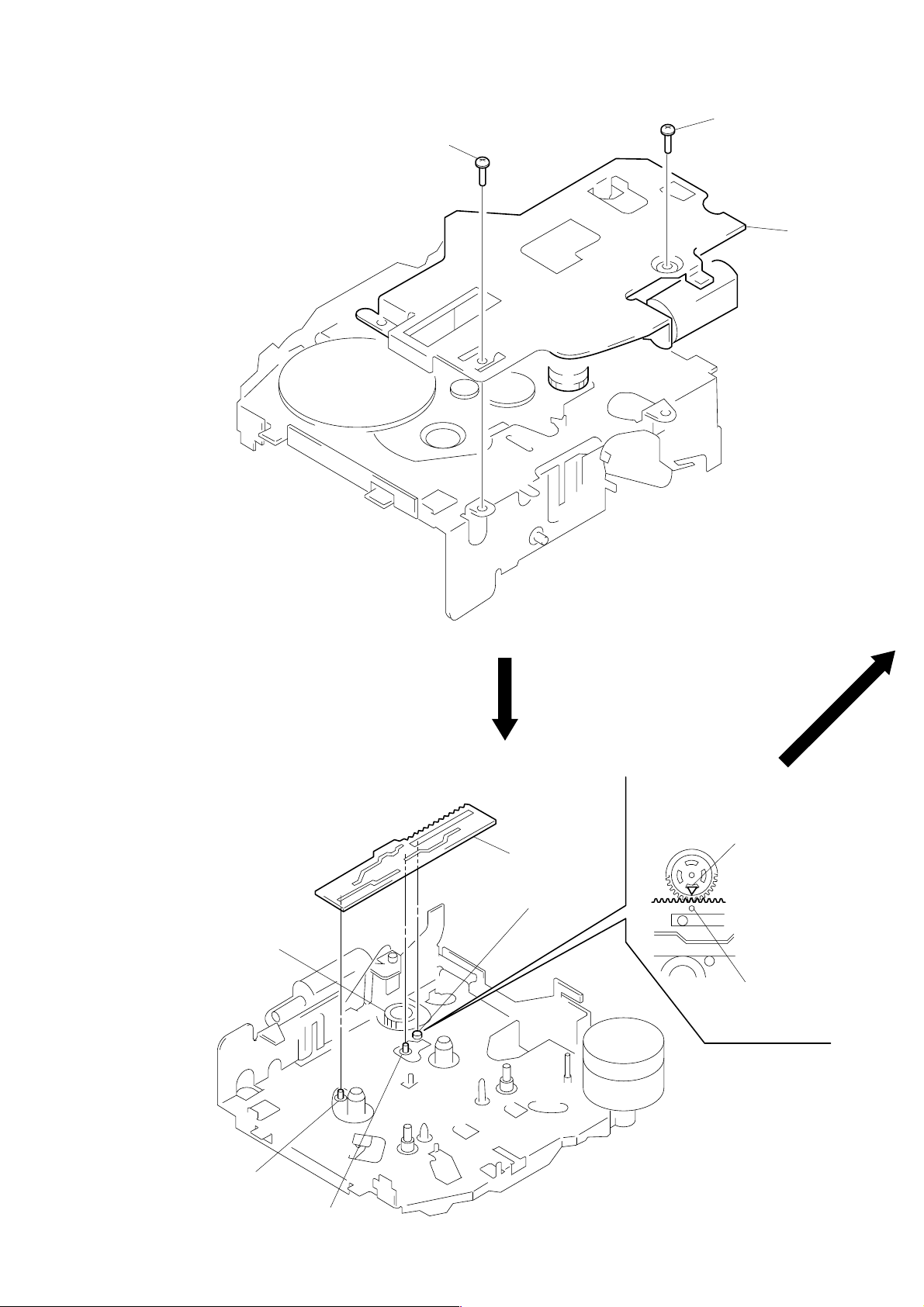
CHASSIS (S) ASS’Y
2
screw (PS2 × 4)
2
screw (PS2 × 4)
1
chassis (S) ass’y
LEVER (MODE)
1. Align ¢ mark on the rotary switch with
hole in the lever (mode).
2. Fit on positions A, B and C and install
the lever (mode).
rotary switch
lever (mode)
C
¢
mark on rotary switch
hole in lever (mode)
A
B
– 11 –
 Loading...