

Page 1

FM/AM
Cassette Car
Stereo
Installation/Connections
Installation/Connexions
XR- 1100
Sony Corporation © 2000
Page 2

Page 3
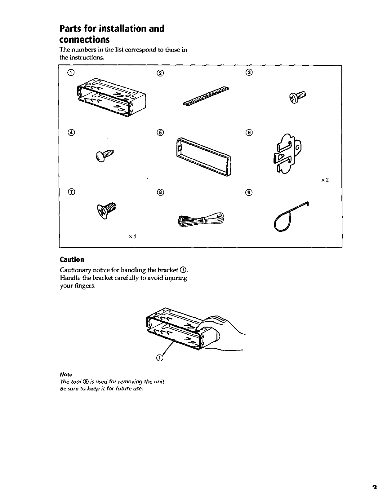
Parts for installation and
connections
The numbers in the list correspond to those in
the instructions.
@ ® @
® ® ®
® @ ®
x2
×4
Caution
Cautionary notice for handling the bracket (D.
Handle the bracket carefully to avoid injuring
your fingers.
Note
The tool (_ is used for removing the unit.
Be sure to keep it for future use.
Page 4
Connections
Caution
• This unit is designed for negative ground 12 V DC operation only.
• Before making connections, disconnect the ground terminal of the car battery to avoid short circuits.
• Connect the yellow and red power input leads only after all other leads have been connected.
• Be sure to connect the red power input lead to the positive 12 V power terminal which is energized
when the ignition key is in the accessory position.
* Run all ground wires to a common ground point.
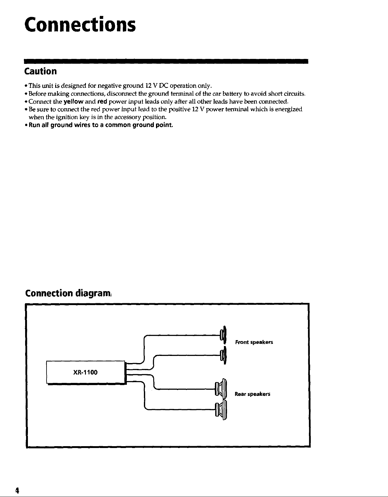
Connection diagram
XR-1100
Front speakers
Rearspeakers
4
Page 5
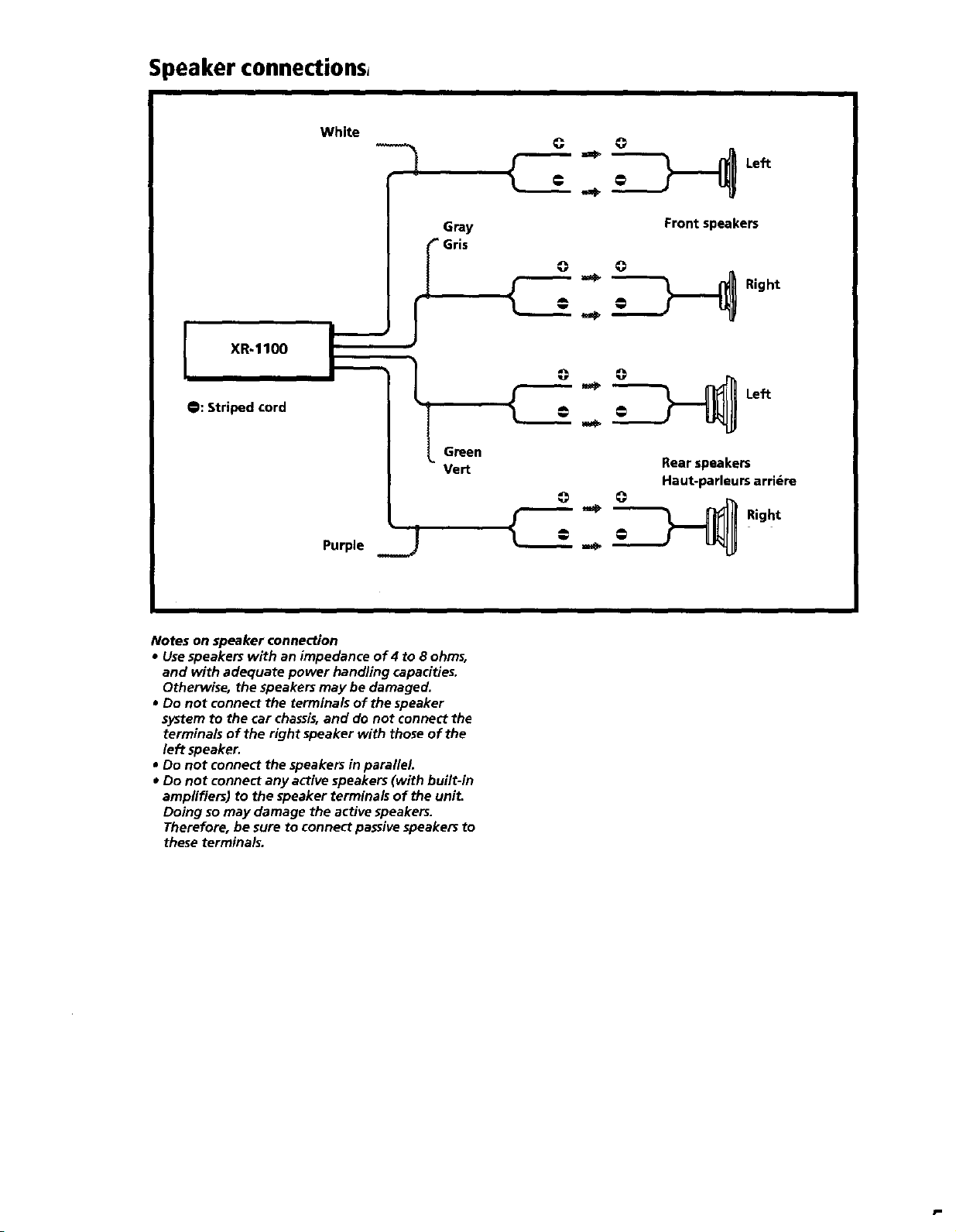
Speaker connections,
XR-1100
O: Striped cord
White
Purple j
Gray
I Gris
L
Green
Vert
C
Front speakers
_*_ _ Right
Rear speakers
Haut-parleurs arri_re
°"
Left
Right
Notes on speaker connection
• Use speakers with an impedance of 4 to 8 ohms,
and with adequate power handling capacities.
Otherwise, the speakers may be damaged.
• Do not connect the terminals of the speaker
system to the car chassis,and do not connect the
terminals of the right speaker with those of the
left speaker.
• Do not connect the speakers in parallel.
* Do not connect any active speakers (with built-in
amplifiers) to the speaker terminals of the unit.
Doing so may damage the active speakers.
Therefore, be sure to connect passive speakers to
these terminals.
P
Page 6

Connection example,
to the +12 V power terminal which is
energized In the accessory position of the
ignition key switch.
Be sure to connect the black earth lead to
it first.
XR-1100
from a car antenna
Red
to the +12 V power terminal which is
energized at all times. _ |
Be sure to connect the black earth lead _ Yellow
first.
Front speakers
Reerspeake_
Notes on the control leads
• The power antenna control lead (blue) supplies 12V DC when you turn on the unit.
• When your car has a built-in FM/AM antenna in the rear/side glass, it is necessary to connect the power
antenna control lead (blue) or the accessory power input lead (red) to the 130wer terminal of the existing
antenna booster. For details, consult your dealer.
• A power antenna without relay box cannot be used with this unit.
6
Page 7

-1100
Fuse (10 A)
to the power antenna control lead or power
supply lead of antenna booster amplifier
Notes
• It is not necessary to connect this lead if there
is no power antenna or antenna booster, or
with a manually-operated telescopic antenna,
• When your car has a built-in FM/AM antenna
in the rear/side glass, see _Notes on the
control leads. _
Blue
I ANT REM
Max. supply current 0.1 A
Black
I
to a metal point of the car,
First connect the black earth lead, then connect
the yellow and red power input leads.
7
Page 8

I
Removing the unit
1 Insert the supplied tool _) between the unit and the frame, and rotategO ° to release the
hidden mounting spring. Repeat on the opposite side and remove the frame.
2 Insert a flathead screwdriver between the bracket and mounting spring. Gently pry the
spring toward the unit while pulling the unit out a little. Repeat on the opposite side and
remove the unit.
1
8
Page 9

2
4 mm (3/,6 In./po.)
n
Page 10

Installation
Precautions
• Choose the installing location carefully so that
the unit will not interfere with driving.
• Avoid installing the unit where it would be
subject to high temperatures, such as direct
sunlight or hot air from the heater, or where it
would be subject to dust, dirt, or excessive
vibration.
• Use only the supplied mounting hardware for
safe and secure installation.
Mounting example
Installing in the dashboard
1
Mounting angle adjustment
Adjust the mounting angle to less than 20 °.
2
_ove the bracket.
10
Page 11

Installation
3
Bend these clews, if necessary.
11
Page 12

4
5
®
Mounting the unit in a Japanese car
This unit may not be installed in some makes of cars. In this case, consult your nearest Sony dealer.
TOYOTA
to dashboard/center console
au tableau de bord/console centrale
(_) max. size _5 x 8 mm
Dimension max.
e5×8mm
Bracket
Suppo_
Note
To prevent malfunction, install only with the supplied screws _).
NISSAN
(_) max. size e5 x 8 mm
Dimension max.
oSx8mm
12
Page 13

I
To support the unit
Dashboard
Fire wall
NISSAN
(_ max, size 05 × B mm
to dashboard/centerconsole
(_ ma)_ size e5 x Bmm
Bracket
Page 14

Sony Corporation Printed in USA
 Loading...