

1277-2384 Rev 3
Sony Mobile Communications AB – Company Internal
Go/No Go Test
Xperia
TM
M, Xperia
TM
M Dual
C1904, C1905, C2004, C2005
Sony Mobile Communications AB – Company Internal
2(8)
Test and Calibration Repair Instruction
CONTENTS
1 Go/No Go Testing ........................................................................... 3
1.1 Antenna Coupler .................................................................................. 3
1.2 Direct Line ............................................................................................ 4
1.3 Attenuation Factors ............................................................................. 6
1.3.1 Loss Values – Antenna Coupler ................................................................. 6
1.3.2 Loss Values – Direct Line ........................................................................... 7
2 Revision History ............................................................................. 8
This product is ONLY implemented in SERP II
1277-2384 Rev 3
Sony Mobile Communications AB – Company Internal
3(8)
1.1 Antenna Coupler
A FEDB C G H I NMLJ K O P Q R
25
15
16
17
18
19
20
21
22
23
24
14
4
5
6
7
8
9
10
11
12
13
1
2
3
A FEDB C G H I NMLJ K O P Q R
25
15
16
17
18
19
20
21
22
23
24
14
4
5
6
7
8
9
10
11
12
13
1
2
3
Test and Calibration Repair Instruction
1 Go/No Go Testing
This Go/No Go testing has to be carried out in two ways, with an:
• Antenna Coupler.
• Cable in shield box
For more information on Antenna Coupler and Cable in shield box testing, refer to
1220-1336: Generic Repair Manual – electrical, section ‘Setup Go/NoGo Test’!
For part no’s on the equipment below, refer to the ‘Tools Catalogue/Matrix’!
The following equipment has to be used:
• Rohde & Schwartz RF Shield Package
- Rohde & Schwartz RF Shield Box
- Rohde & Schwartz RF Coupler
- Grid Positioning Holder
• RF Test Cable Flexible 1M
• RF Adapter for RF Shield Box
• USIM Card, instrument specific
GSM-850/900/1800/1900
WCDMA-850/900/1700/1900/2100
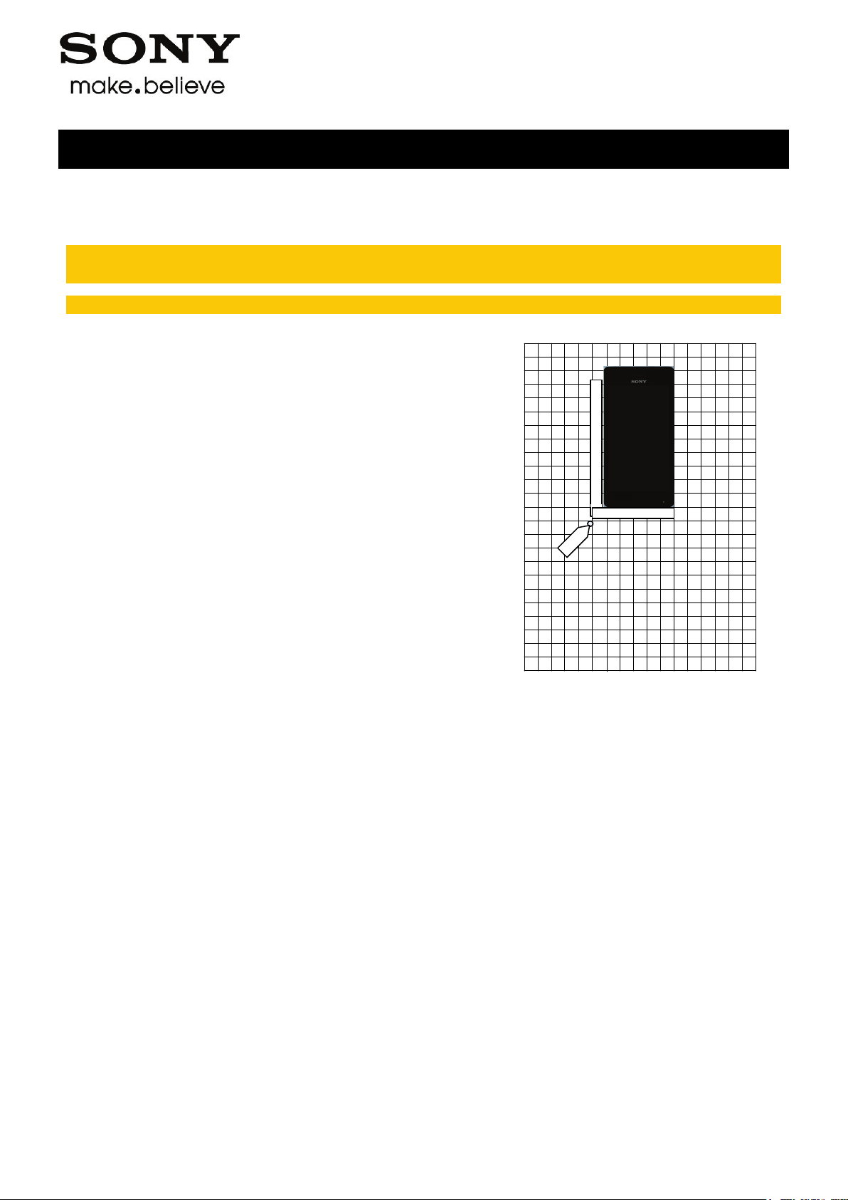
Put the grid positioning holder with its reference point in
position F12 and place the phone as shown in the adjacent
picture.
1277-2384 Rev 3

Sony Mobile Communications AB – Company Internal
4(8)
Go/NoGo Testing
1.2 Direct Line
The following equipment has to be used:
• RF Test Cable Flexible 1M
• RF Probe
• USIM Card, instrument specific
Connect the RF Probe as shown in the adjacent picture.
To get access to the RF connector on the PBA, refer to
1277-1343: C1904, C1905, C2004, C2005 Mechanical
Working Instructions, Chapter 3.1!
Test and Calibration Repair Instruction
1277-2384 Rev 3

Sony Mobile Communications AB – Company Internal
5(8)
Test and Calibration Repair Instruction
Go/NoGo Testing
Follow the directions stated in ‘Go/NoGo Test Script Parameters’ to be found in
1220-1336: Generic Repair Manual – electrical, together with the ‘Attenuation Factors’ below!
This phone is available as 4 versions, C1904, C1905, C2004 and C2005 including the following bands:
C1905, C2005:
GSM-850/900/1800/1900
WCDMA-900/2100
C1904, C2004:
GSM-850/900/1800/1900
WCDMA-850/1700/1900/2100
1277-2384 Rev 3

Sony Mobile Communications AB – Company Internal
6(8)
Attenuation
Attenuation
C1905/C2005
C1904/C2004
Band
Channel
Rx
Tx
Rx
Tx
- - 6.75
11.56
- - 6.75
10.33
- - 6.75
8.89
13.25
17.22
12.25
15.46
12.50
15.07
- - 13.25
18.62
- - 14.75
17.19
- - 14.75
13.59
Test and Calibration Repair Instruction
Go/NoGo Testing
1.3 Attenuation Factors
The attenuation values listed below in 1.3.1 are valid only when the equipment listed on the
previous pages is being used!
1.3.1 Loss Values – Antenna Coupler
Low 5.75 11.77 7.00 11.89
GSM 850
GSM 900
GSM 1800
GSM 1900
WCDMA 850
WCDMA 900
Mid 6.00 10.27 7.00 10.36
High 7.50 8.81 7.25 8.95
Low 7.00 5.93 9.75 5.90
Mid 5.75 6.60 6.00 6.84
High 6.75 6.83 6.75 7.01
Low 14.75 17.50 15.00 17.76
Mid 16.25 15.41 17.25 15.45
High 15.00 15.50 16.25 15.51
Low 15.00 16.93 17.00 17.40
Mid 15.25 14.90 15.00 15.10
High 15.00 13.65 15.00 13.79
Low
Mid
High
Low 6.75 6.22 - -
Mid 5.75 6.06 - -
High 6.50 6.37 - -
Low
WCDMA 1700
WCDMA 1900
WCDMA 2100
Mid
High
Low
Mid
High
Low 12.75 12.36 13.00 12.39
Mid 12.25 13.01 12.25 12.91
High 12.00 15.49 11.50 15.25
1277-2384 Rev 3

Sony Mobile Communications AB – Company Internal
7(8)
Attenuation
Band
Channel
Rx
Tx
Test and Calibration Repair Instruction
Go/NoGo Testing: Attenuation Factors
1.3.2 Loss Values – Direct Line
GSM 850 All 1.0 1.0
GSM 900 All 1.0 1.0
GSM 1800 All 2.3 2.3
GSM 1900 All 2.3 2.3
WCDMA 850 All 1.3 1.3
WCDMA 900 All 1.3 1.3
WCDMA 1700 All 1.3 1.3
WCDMA 1900 All 2.3 2.3
WCDMA 2100 All 2.5 2.5
1277-2384 Rev 3

Sony Mobile Communications AB – Company Internal
8(8)
Rev.
Date
Changes / Comments
2 Revision History
1 2013-Jul-29 Initial release
2 2013-Sep-25 Added C2004 and C2005
3 2013-Okt-27 Moved to SL2
Test and Calibration Repair Instruction
1277-2384 Rev 3
 Loading...