

Sony Xperia E3 Schematics
Working Instructions
- mechanical -
TM
Xperia
E3 & E3 Dual
D2202, D2203, D2206, D2212, D2243
1291-1031 Rev 3
©
Sony Mobile Communications – Company Internal

Working Instruction Repair Instruction Mechanical/
CONTENTS
1Exterior Views ................................................................................. 4
1.1 D2202, D2203, D2206, D2212, D2243 ................................................... 4
2Tools ................................................................................................ 5
3Disassembly.................................................................................... 6
3.1 Battery Cover ........................................................................................ 6
3.2 Rubber Corner & Screw 1.6mm x 3.2mm ............................................ 7
3.3 Rear Cover Assy .................................................................................. 7
3.4 Camera Main ......................................................................................... 9
3.5 Main PBA ............................................................................................ 10
3.6 Sub PBA .............................................................................................. 11
3.7 Battery 2300 mAh & Front Cover Assy ............................................. 12
4Replacement ................................................................................. 14
4.1 Battery Cover ...................................................................................... 14
4.2 Rubber Corner .................................................................................... 14
4.3 Screw 1.6mm x 3.2mm ....................................................................... 14
4.4 Rear Cover Assy ................................................................................ 14
4.5 Camera Main ....................................................................................... 15
4.6 Main PBA ............................................................................................ 15
4.7 Sub PBA .............................................................................................. 15
4.8 Battery 2300 mAh ............................................................................... 15
4.9 Front Cover Assy ............................................................................... 16
4.10 Battery Adhesive-1 ............................................................................. 17
4.11 Battery Adhesive-2 ............................................................................. 18
4.12 CU Label ............................................................................................. 19
4.13 Key Power/Vol .................................................................................... 20
4.14 Liquid Intrusion Label “Main PBA” ................................................... 21
4.15 Liquid Intrusion Label Sub PBA ........................................................ 22
4.16 Loudspeaker ....................................................................................... 23
4.17 Proximity Sensor Rubber Gasket...................................................... 24
4.18 Receiver .............................................................................................. 25
4.19 Receiver Sponge ................................................................................ 26
4.20 RF Cable ............................................................................................. 27
4.21 Side Key FPC ...................................................................................... 28
4.22 VGA Rubber ........................................................................................ 29
4.23 Board Swap – Replacement .............................................................. 30
4.24 Board Swap – Change Label ............................................................. 30
4.25 Board Swap – Customize of Software .............................................. 30
1291-1031 Rev 3
©
Sony Mobile Communications – Company Internal
2(36)

Working Instruction Repair Instruction Mechanical/
5Reassembly................................................................................... 31
5.1 Front Cover Assy & Battery 2300 mAh ............................................. 31
5.2 Sub PBA .............................................................................................. 32
5.3 Main PBA ............................................................................................ 32
5.4 Rear Cover Assy ................................................................................ 34
5.5 Screw 1.6mm x 3.2mm & Rubber Corner.......................................... 35
5.6 Battery Cover ...................................................................................... 35
6Revision History ........................................................................... 36
For general information about mechanical repair related issues, refer to
1220-1333: Generic Repair Manual - mechanical
1291-1031 Rev 3
©
Sony Mobile Communications – Company Internal
3(36)
Working Instruction Repair Instruction Mechanical/
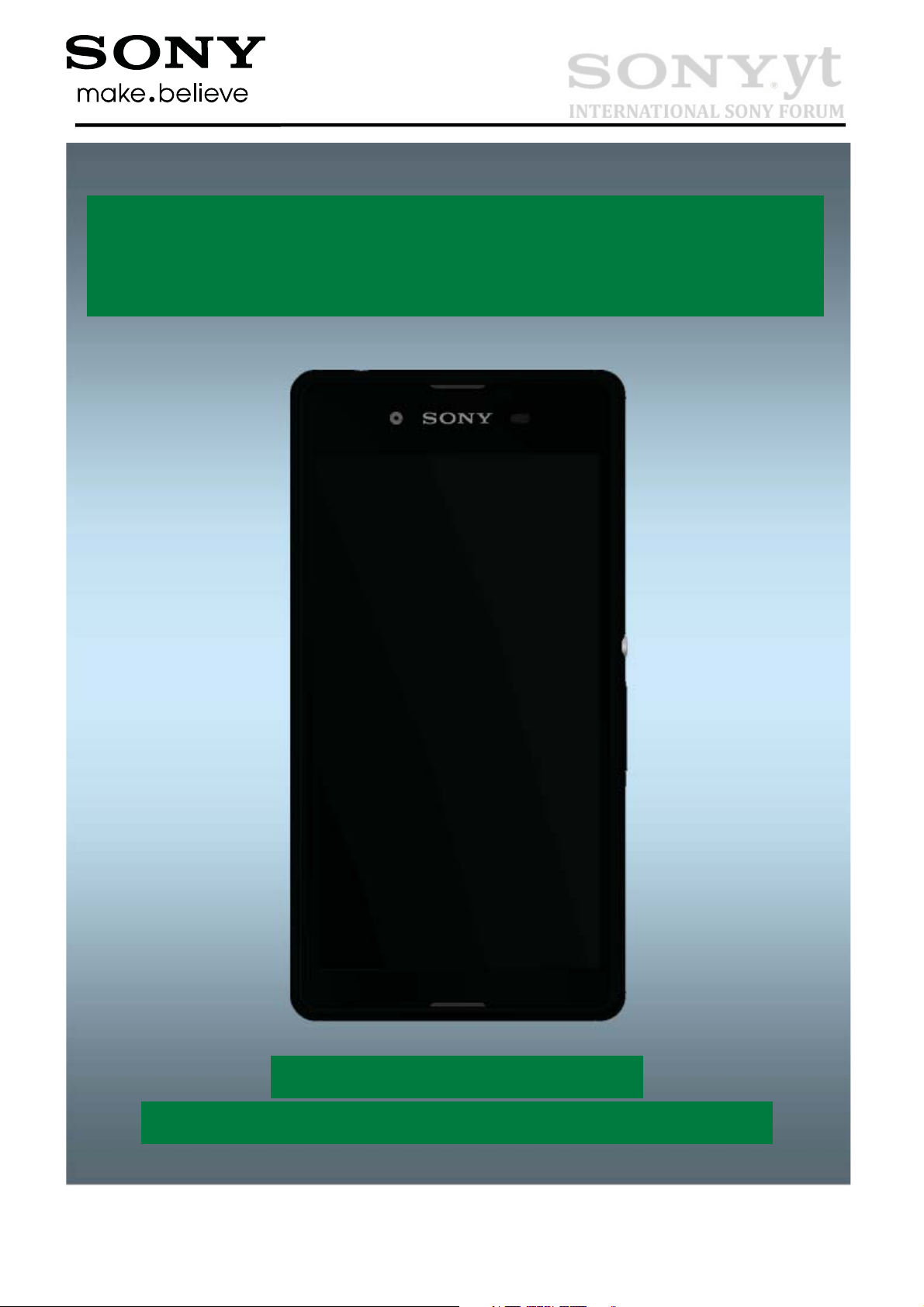
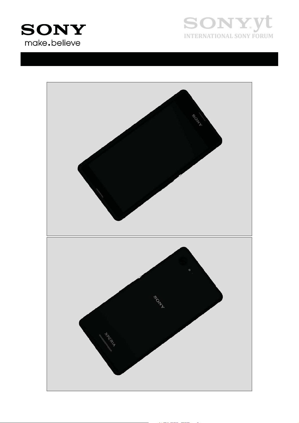
1 Exterior Views
1.1 D2202, D2203, D2206, D2212, D2243
1291-1031 Rev 3
©
Sony Mobile Communications – Company Internal
4(36)
Working Instruction Repair Instruction Mechanical/
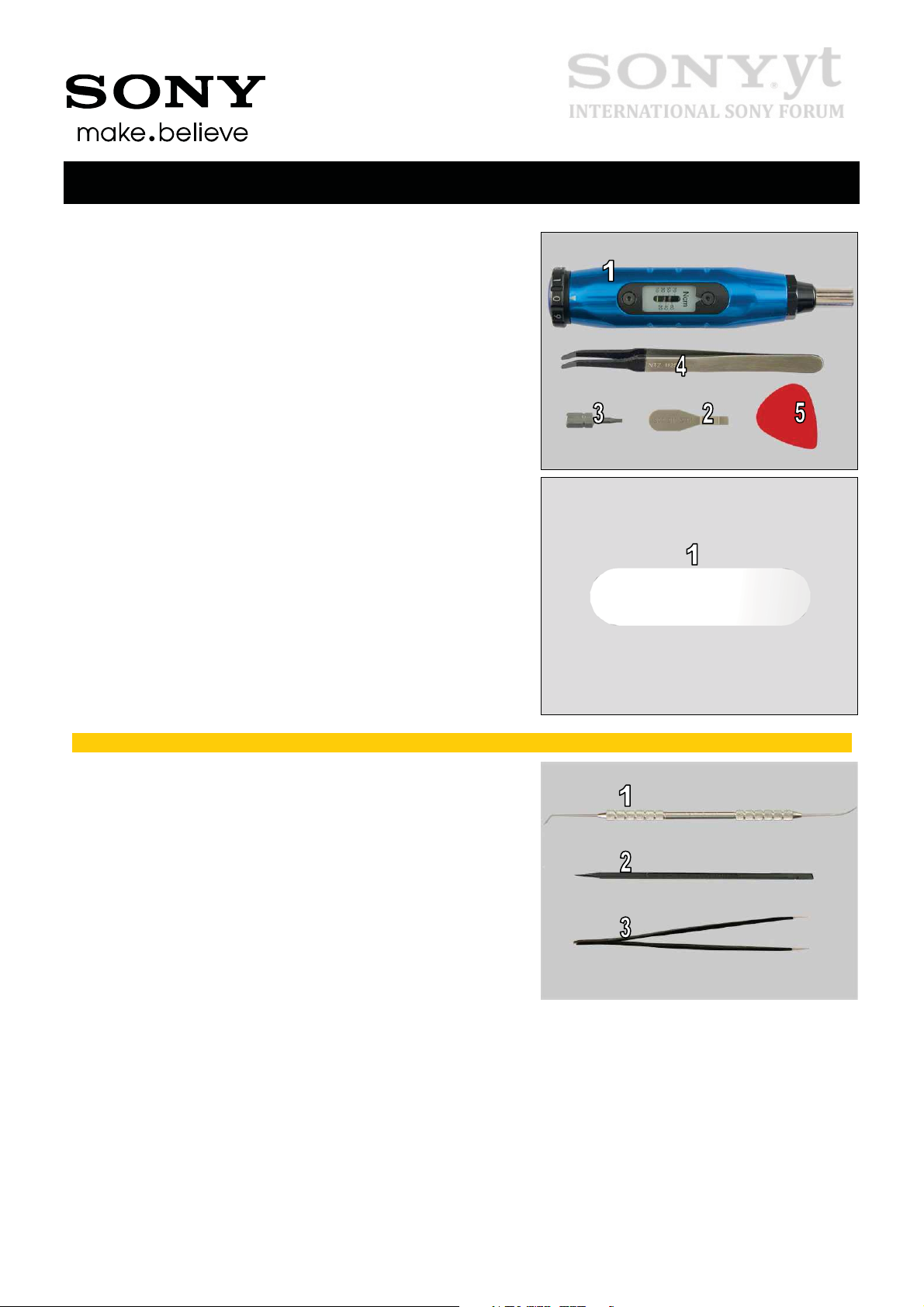
2 Tools
SPECIAL TOOLS
1. Torque Screwdriver
2. Front Opening Tool
3. Torx Bit T5
4. Flex Film Assembly Tool
5. Guitar Pick
SPECIAL TOOLS
1. Flexible Disassembly tool
For part no’s on the tools above, refer to the ‘Tools Catalogue/Matrix’!
STANDARD TOOLS
1. Dentist Hook
2. Nylon Pointer
3. Tweezers
1291-1031 Rev 3
©
Sony Mobile Communications – Company Internal
5(36)
Working Instruction Repair Instruction Mechanical/
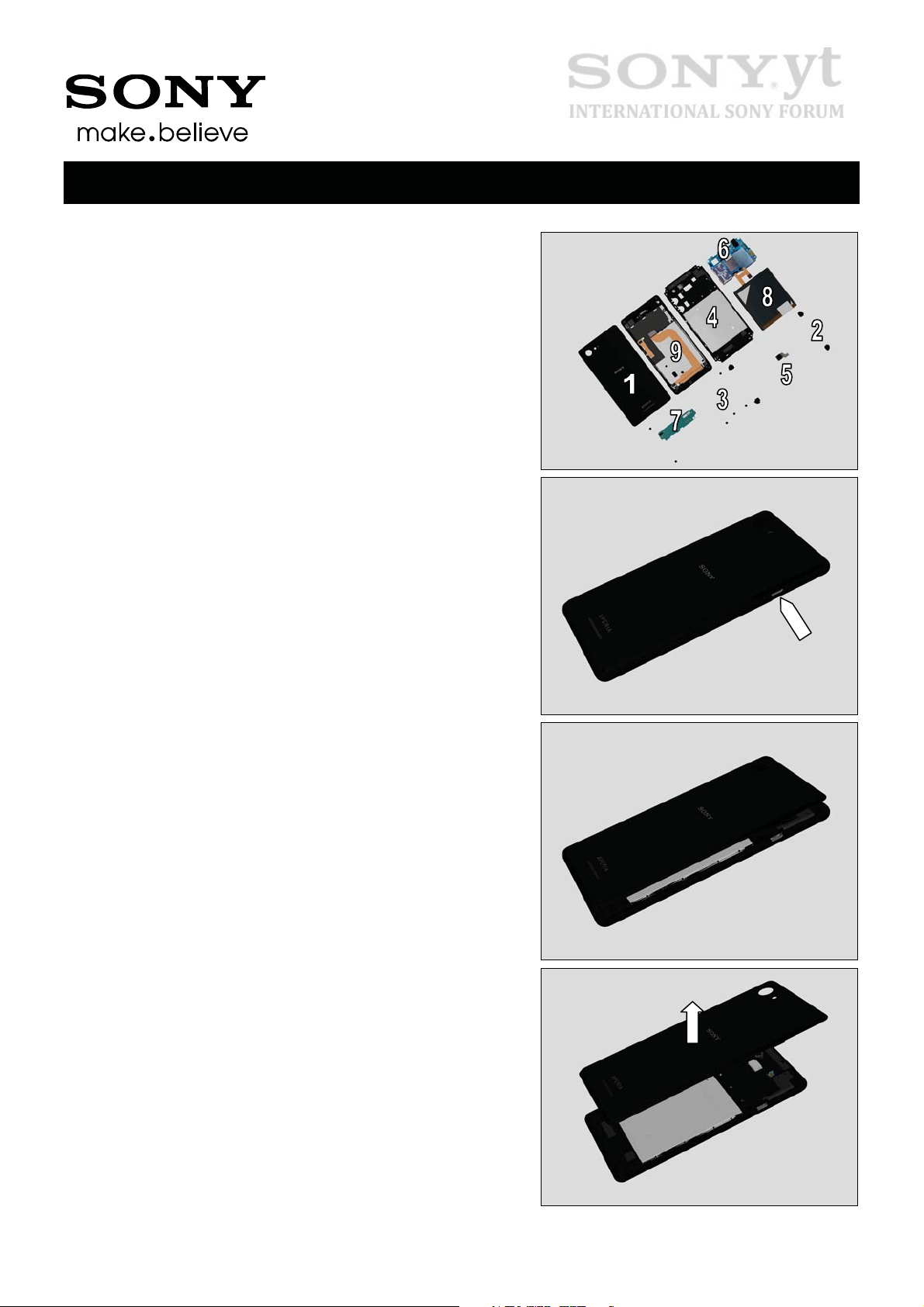
3 Disassembly
The disassembly is done in the following order:
1. Battery Cover
2. Rubber Corner
3. Screw 16mm x 3.2mm
4. Rear Cover Assy
5. Camera Main
6. Main PBA
7. Sub PBA
8. Battery 2300 mAh
9. Front Cover Assy
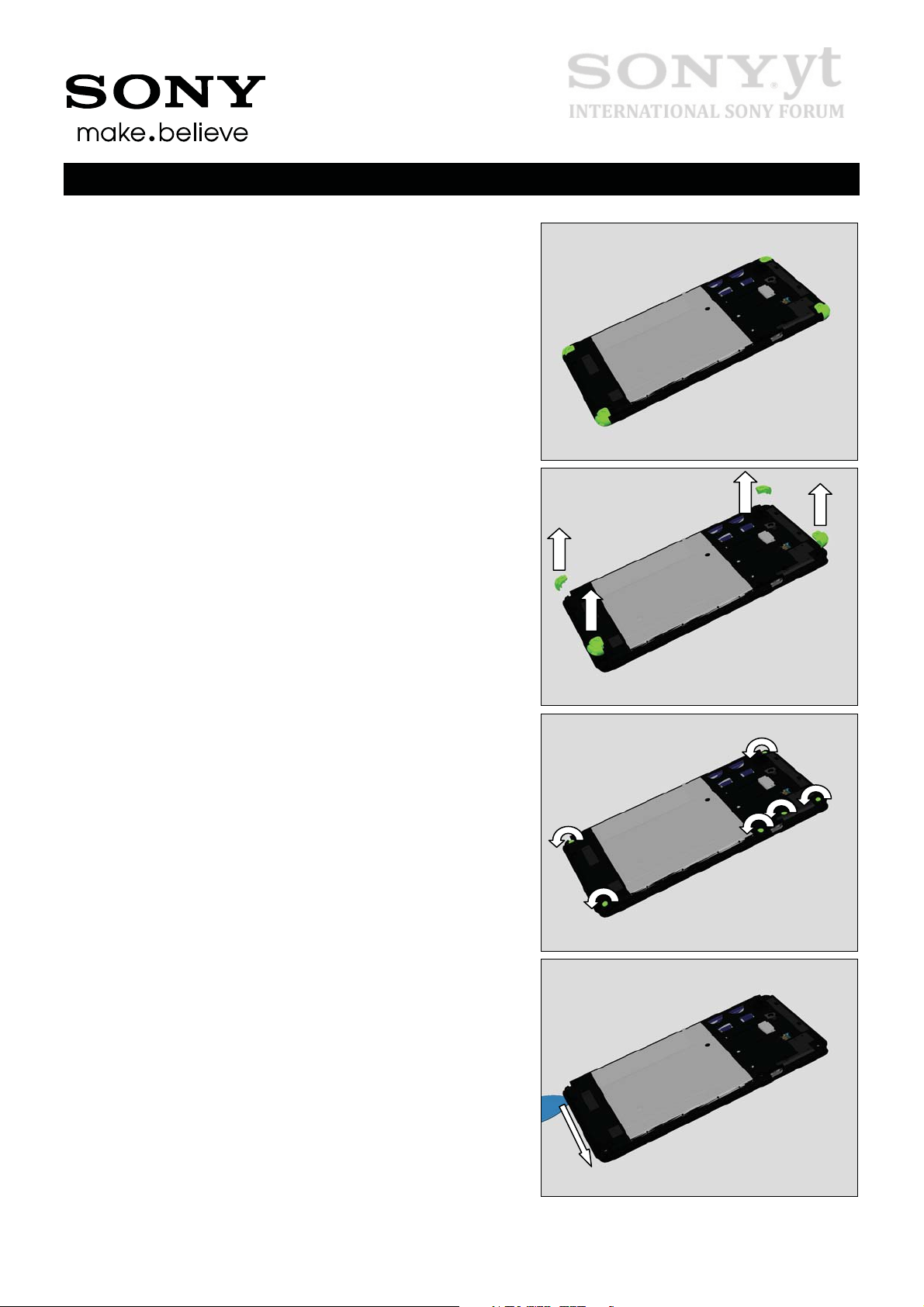
3.1 Battery Cover
Loosen Battery Cover at USB connector area using finger as
shown in picture.
Lift up the Battery Cover.
Remove Battery Cover with fingers
1291-1031 Rev 3
©
Sony Mobile Communications – Company Internal
6(36)
Working Instruction Repair Instruction Mechanical/
Disassembly
3.2 Rubber Corner & Screw
1.6mm x 3.2mm
Loosen four Rubber Corner using dentist hook.
Remove the four Rubber Corner parts using fingers.
Remove six, Screw 1.6mm x 3.2mm by using Torx Bit T5.
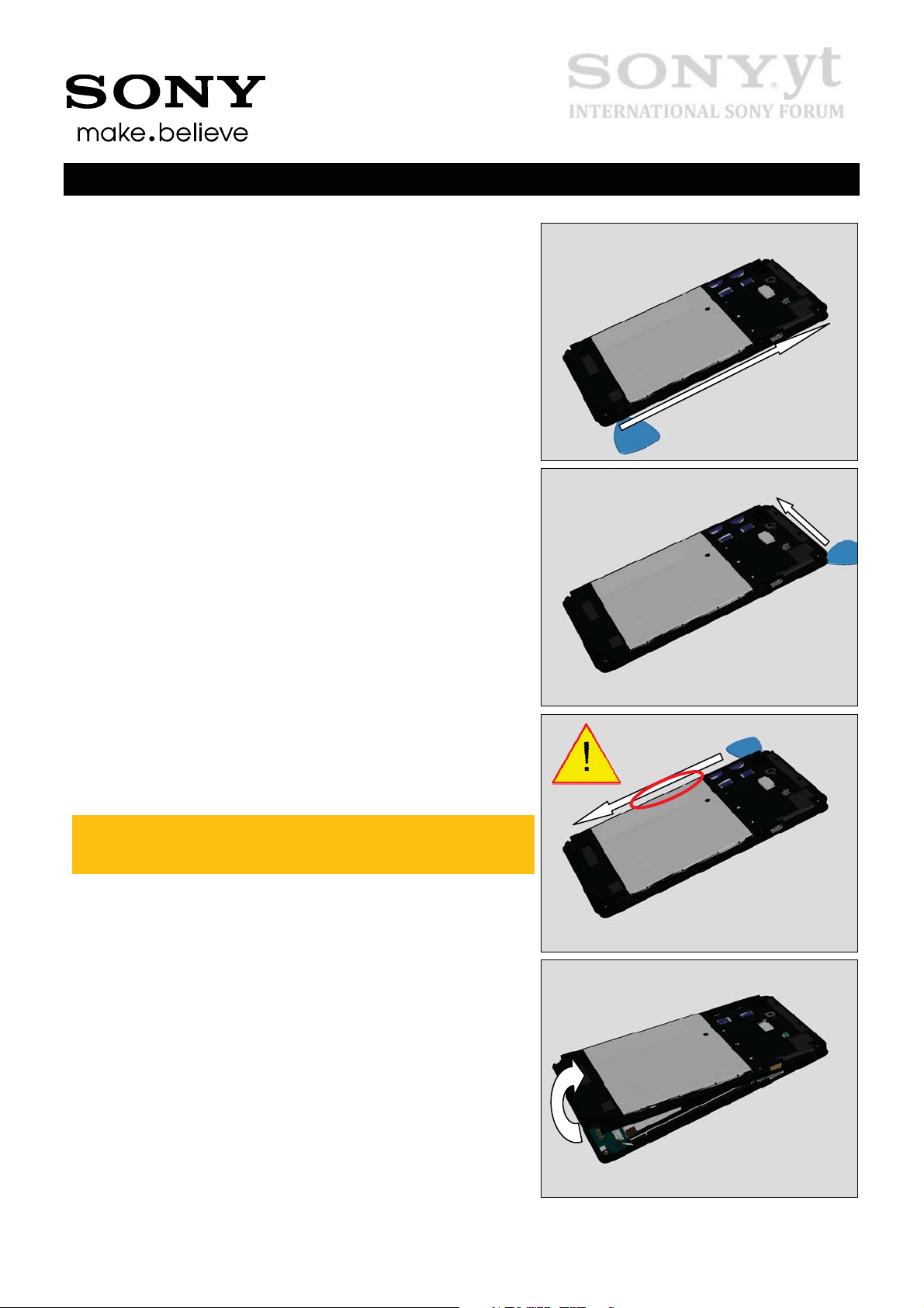
3.3 Rear Cover Assy
Insert Guitar Pick into Rear Cover Assy as shown in picture
and slide along bottom side as shown in picture.
1291-1031 Rev 3
©
Sony Mobile Communications – Company Internal
7(36)
Working Instruction Repair Instruction Mechanical/
Disassembly
Slide Guitar Pick along side of phone to unsnapping all
hooks.
Repeat same action for topside.
Repeat same action for last side.
Be careful not to use too much force at Key Power/Vol
area as shown in picture, it may cause damage to Rear
Cover Assy!
Tilt up Rear Cover Assy from bottom side using fingers as
shown in picture.
1291-1031 Rev 3
©
Sony Mobile Communications – Company Internal
8(36)
Working Instruction Repair Instruction Mechanical/
Disassembly
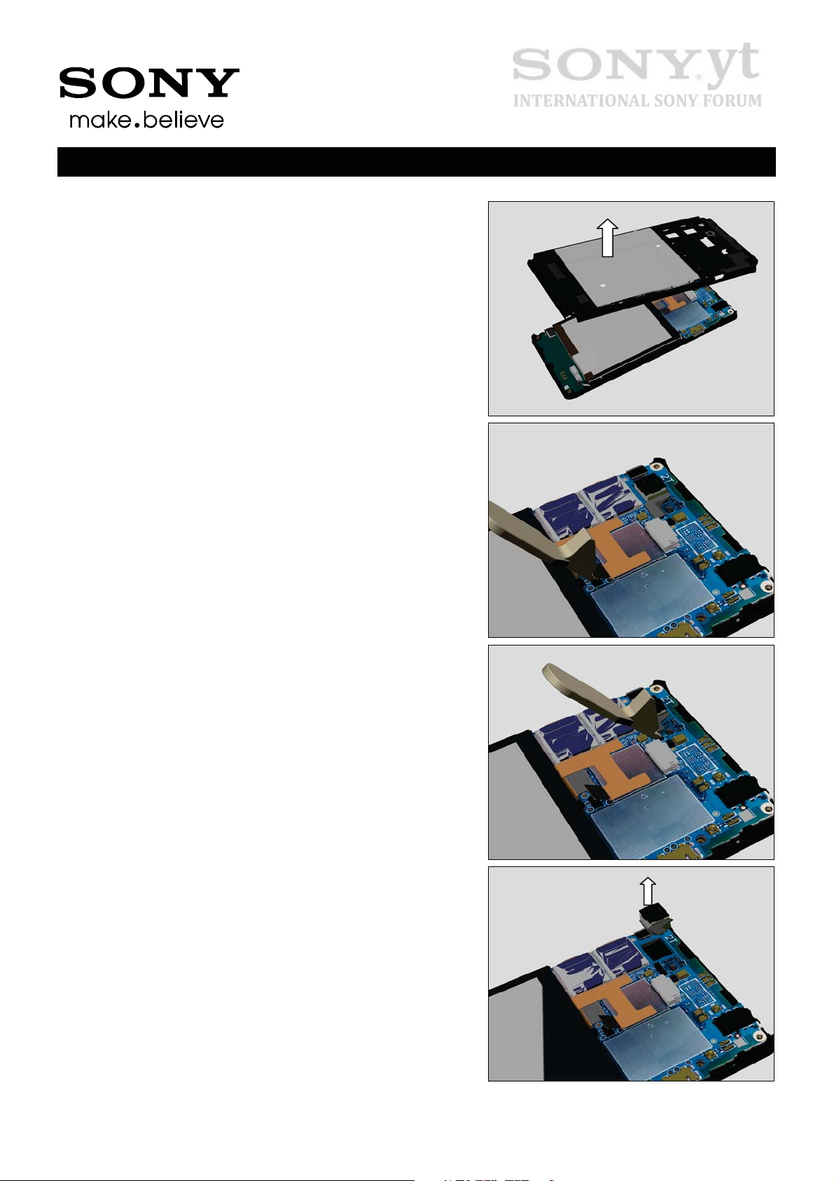
Remove using fingers.
3.4 Camera Main
Use Front Opening Tool to disconnect Battery 2300 mAh
board-to-board (BtB) connector to cut to power to Main PBA.
Use Front Opening Tool to disconnect Camera Main boardto-board (BtB) connector.
Remove Camera Main using fingers gripping at the sides.
1291-1031 Rev 3
©
Sony Mobile Communications – Company Internal
9(36)
Working Instruction Repair Instruction Mechanical/
Disassembly
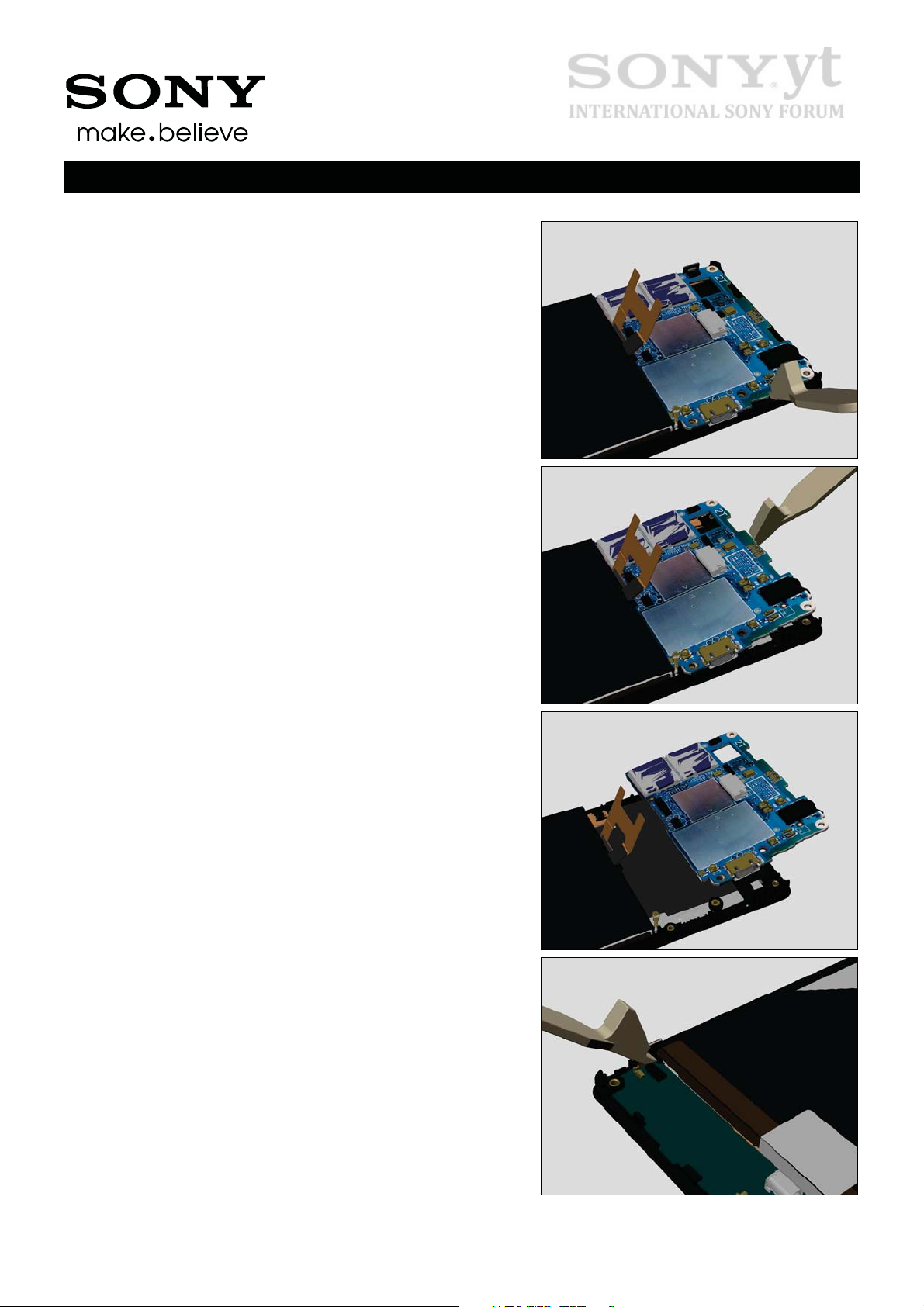
3.5 Main PBA
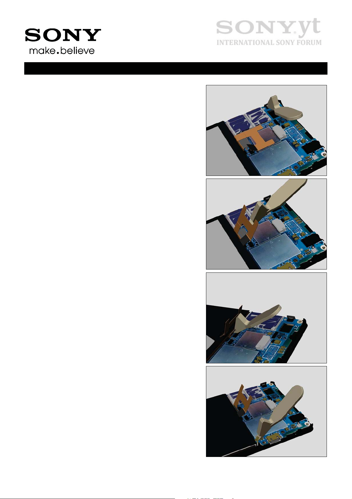
Use Front Opening Tool to disconnect Touch Panel boardto-board (BtB) connector.
Use Front Opening Tool to raise up the Battery 2300 mAh
board-to-board (BtB) connector.
Use Front Opening Tool to disconnect LCD FPC board-toboard (BtB) connector.
Use Front Opening Tool to disconnect RF Cable board-toboard (BtB) connector Main PBA.
1291-1031 Rev 3
©
Sony Mobile Communications – Company Internal
10(36)
Working Instruction Repair Instruction Mechanical/
Disassembly
Use Front Opening Tool to release snap hook at side of
Main PBA.
Use Front Opening Tool to rise up Main PBA at the side
releasing snap hook.
Remove Main PBA.
3.6 Sub PBA
Use Front Opening Tool to disconnect LCD FPC board-toboard (BtB) connector Sub PBA.
1291-1031 Rev 3
©
Sony Mobile Communications – Company Internal
11(36)
 Loading...