

T
M
T
M
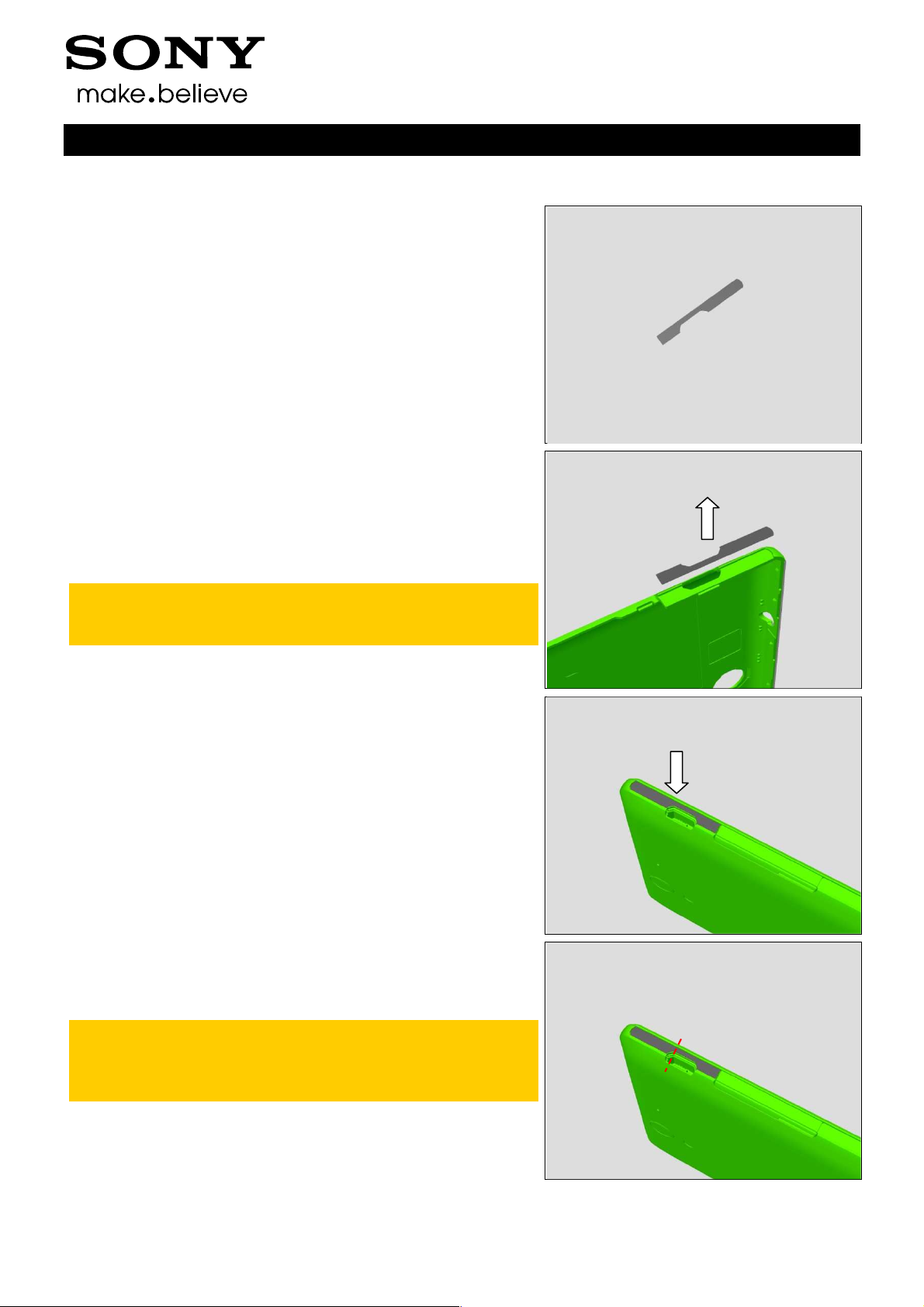
Working Instructions
- mechanical -
Xperia
C3 Dual
S55t, S55u, D2502
1290-1182 Rev 4
Sony Mobile Communications AB – Company Internal
Xperia
D2533
C3

Company Internal
Working Instructions (mech)
CONTENTS
1 Exterior Views ................................................................................. 4
1.1 S55t/S55u/D2533/D2502 ....................................................................... 4
2 Tools ................................................................................................ 5
3 Disassembly.................................................................................... 6
3.1 SIM Tray ................................................................................................ 7
3.2 Back Cover Assy .................................................................................. 7
3.3 Ant Top Frame Assy .......................................................................... 14
3.4 2nd Mic Rubber .................................................................................. 15
3.5 Main Camera ....................................................................................... 16
3.6 Chat Camera ....................................................................................... 16
3.7 Main PBA ............................................................................................ 17
3.8 Core Unit label Tray ........................................................................... 18
3.9 Ant Speaker Bottom Frame Assy (a) and Display Frame Assy (b) . 18
4 Replacement ................................................................................. 20
4.1 2nd Mic Rubber .................................................................................. 20
4.2 Ant Speaker Bottom Frame Assy ...................................................... 20
4.3 Ant Top Frame Assy .......................................................................... 20
4.4 Back Cover Assy ................................................................................ 20
4.5 Chat Camera ....................................................................................... 21
4.6 Core Unit label Tray ........................................................................... 21
4.7 Display Frame Assy ........................................................................... 21
4.8 Main Camera ....................................................................................... 21
4.9 SIM Tray .............................................................................................. 22
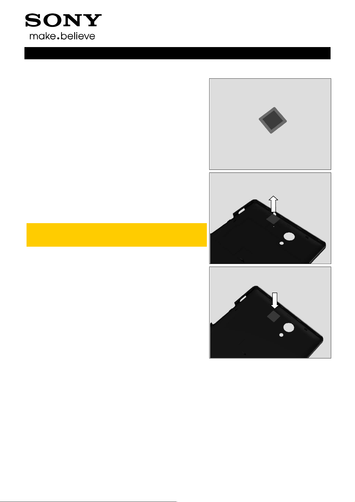
4.10 2nd Mic Mesh ...................................................................................... 23
4.11 Adhesive Battery ................................................................................ 24
4.12 Adhesive Conductive Main FPC ........................................................ 25
4.13 Adhesive Conductive Sub PBA ......................................................... 26
4.14 Adhesive Conductive Vibrator .......................................................... 27
4.15 Adhesive Earspeaker ......................................................................... 28
4.16 Audio Jack Adhesive ......................................................................... 29
4.17 Audio Jack Assy ................................................................................ 30
4.18 Audio Jack Film .................................................................................. 31
4.19 Back Cover Bottom Panel.................................................................. 32
4.20 Back Cover Sidekey Side Lower Panel ............................................. 33
4.21 Back Cover Sidekey Side Middle Panel ............................................ 34
4.22 Back Cover Sidekey Side Upper Panel ............................................. 35
4.23 Back Cover Top Panel ....................................................................... 36
4.24 Back Cover USB Side Lower Panel ................................................... 37
4.25 Back Cover USB Side Upper Panel ................................................... 38
1290-1182 Rev 4
Sony Mobile Communications AB –
2(72)

Company Internal
Working Instructions (mech)
4.26 Battery ................................................................................................. 39
4.27 Battery Release Tape ......................................................................... 40
4.28 Camera Key Assy ............................................................................... 42
4.29 Camera Window ................................................................................. 43
4.30 Core Unit label .................................................................................... 44
4.31 Earspeaker .......................................................................................... 45
4.32 Gasket Chat Camera .......................................................................... 46
4.33 Liquid Indicator .................................................................................. 47
4.34 Main Camera Film .............................................................................. 48
4.35 Main FPC Assy ................................................................................... 49
4.36 Power/Side Key Assy ......................................................................... 51
4.37 Reset Key and Tape Reset Key ......................................................... 52
4.38 RF cable .............................................................................................. 54
4.39 RGB Gasket ........................................................................................ 56
4.40 SD Cap ................................................................................................ 57
4.41 SIM Cap ............................................................................................... 58
4.42 Speaker Mesh ..................................................................................... 59
4.43 Speaker Net ........................................................................................ 60
4.44 Sub PBA .............................................................................................. 61
4.45 Vibrator ............................................................................................... 62
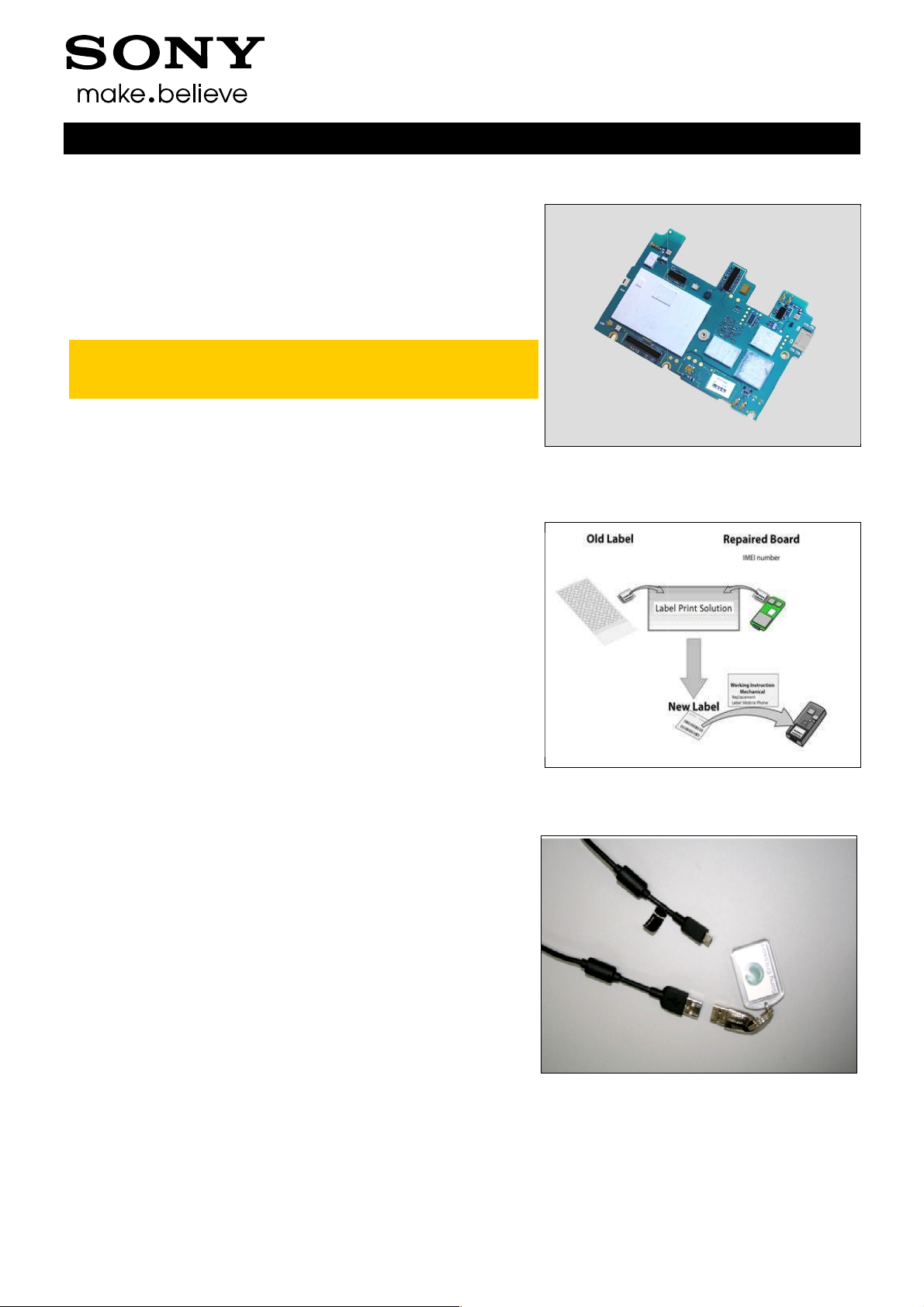
4.46 Board Swap – Replacement .............................................................. 64
4.47 Board Swap – Change Label ............................................................. 64
4.48 Board Swap – Customize of Software .............................................. 64
5 Reassembly................................................................................... 65
5.1 Display Frame Assy (a) and Ant Speaker Bottom Frame Assy (b) . 66
5.2 Core Unit label Tray ........................................................................... 66
5.3 Main PBA ............................................................................................ 67
5.4 Chat Camera ....................................................................................... 68
5.5 Main Camera ....................................................................................... 68
5.6 2nd Mic Rubber .................................................................................. 69
5.7 Ant Top Frame Assy .......................................................................... 69
5.8 Back Cover Assy ................................................................................ 70
5.9 SIM Tray .............................................................................................. 71
6 Revision History ........................................................................... 72
For general information about mechanical repair related issues, refer to
1220-1333: Generic Repair Manual - mechanical
Always firstly disconnect the Battery FPC BtB connector to cut off power supply when the Sub
Antenna Assy is disassembled.
Always finally connect the Battery FPC BtB connector before the Sub Antenna Assy is
reassembled.
1290-1182 Rev 4
Sony Mobile Communications AB –
3(72)
Company Internal
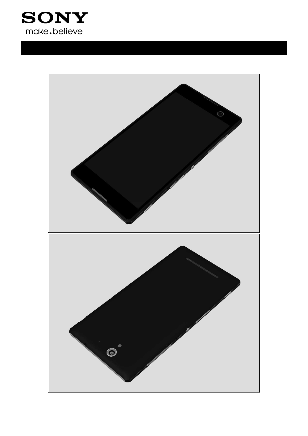
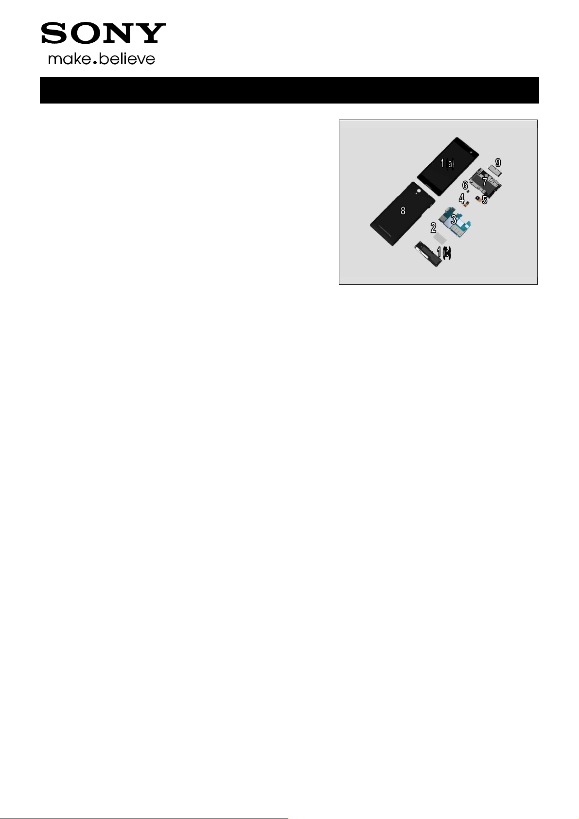
1 Exterior Views
1.1 S55t/S55u/D2533/D2502
Working Instructions (mech)
1290-1182 Rev 4
Sony Mobile Communications AB –
4(72)
Sony Mobile Communications AB
2 Tools
For part no’s on the tools above, refer to the ‘Tools Catalogue/Matrix’!
Working Instructions (mech)
Company Internal
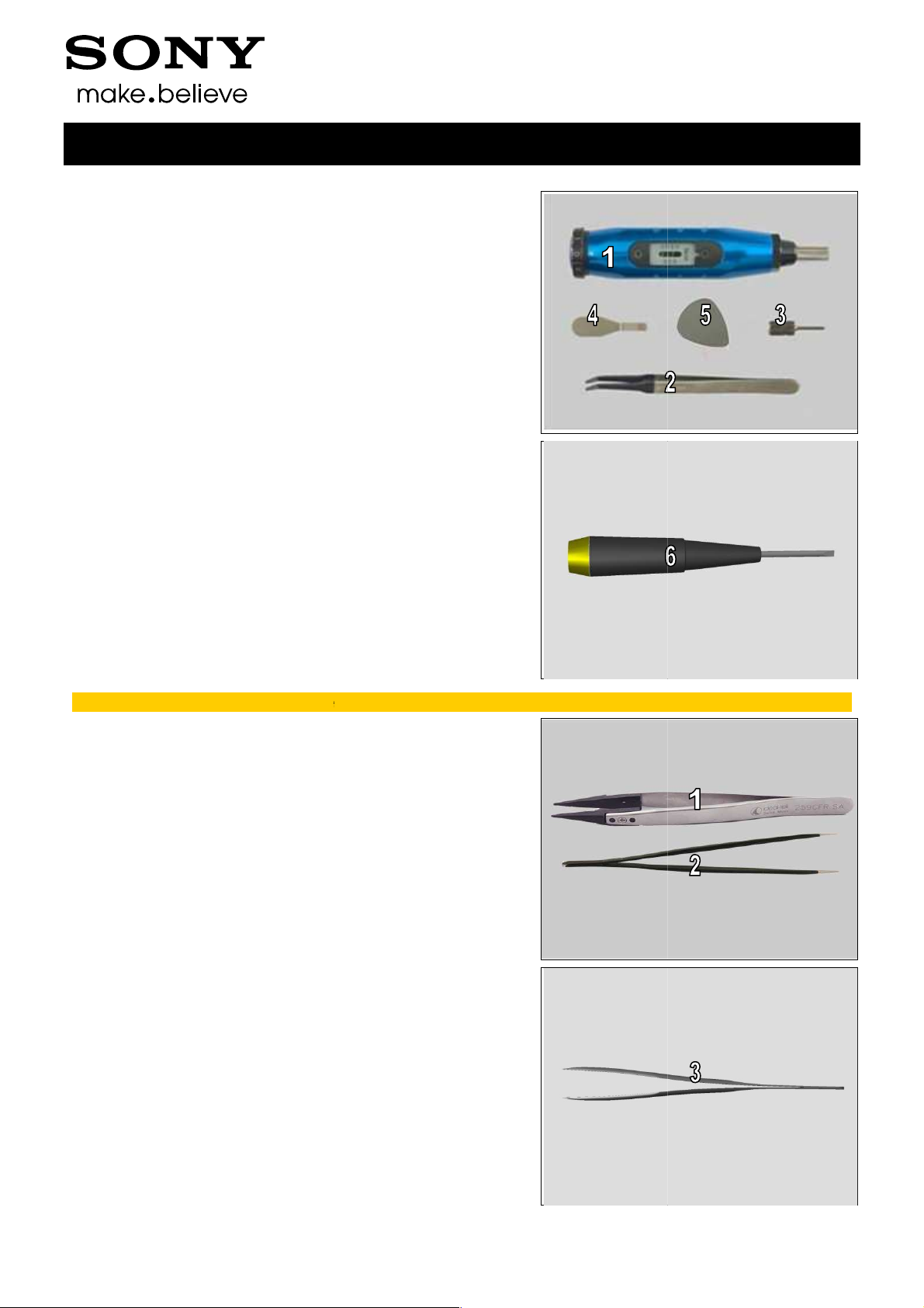
SPECIAL TOOLS
1. Torque Screwdriver
2. Flex Film Assembly Tool
3. Bits JCIS No.0
4. Front Opening Tool
5. Metal Plectrum
6. Flat Screwdriver (
1.5x40
STANDARD TOOLS
1. Plastic Tweezers
2. Pointed-tip Tweezers
)
3. Blunt-tip Tweezers
1290-1182 Rev 4
–
5(72)

Company Internal
3 Disassembly
The S55t/S55u/D2533/D2502 disassembly is done in the
following order:
1. SIM Tray
2. Back Cover Assy
3. Ant Top Frame Assy
4. 2nd Mic Rubber
5. Main Camera
6. Chat Camera
7. Main PBA
8. Core Unit label Tray
9. Ant Speaker Bottom Frame Assy (a) and Display Frame
Assy (b)
Working Instructions (mech)
1290-1182 Rev 4
Sony Mobile Communications AB –
6(72)
Company Internal
Disassembly
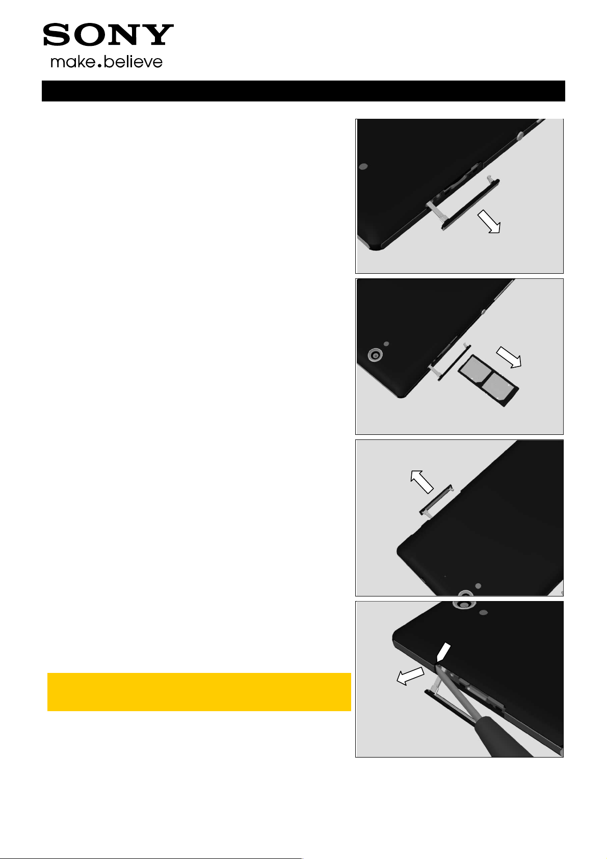
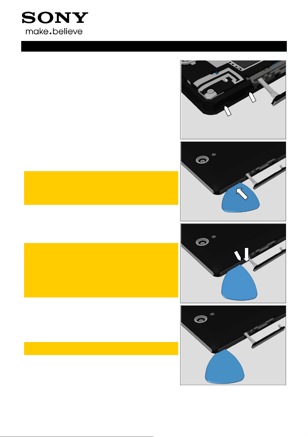
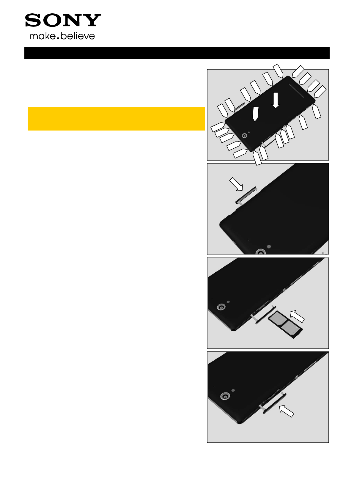
3.1 SIM Tray
Open the SIM Cap.
Remove the SIM Tray with fingers.
Working Instructions (mech)
3.2 Back Cover Assy
Open the SD Cap.
Use the Flat Screwdriver to get space for inserting the Metal
Plectrum.
Note! Make sure to insert the Flat Screwdriver between
the Back Cover Assy and front frame, and do not detach
the Back Cover Panel from the Back Cover Assy.
1290-1182 Rev 4
Sony Mobile Communications AB –
7(72)
Company Internal
Disassembly
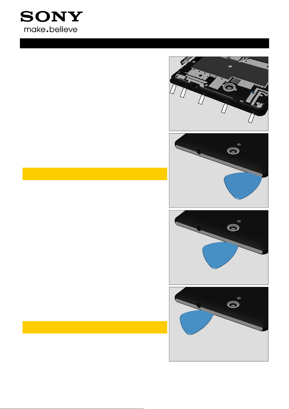
Note the position of hooks!
Insert the Metal Plectrum between the Back Cover Assy and
the front frame.
Note! Do not damage the edge of the front frame and the
Back Cover Panels when inserting.
Make sure to insert the Metal Plectrum to the bottom in
order to lower the risk of damaging the Back Cover
panels when unsnapping the hooks.
Working Instructions (mech)
Use the Metal Plectrum to unsnap this hook as shown in
picture.
Note! Do not damage the edge of the front frame and the
Back Cover Panels when unsnapping.
Make sure that the surface of the Metal Plectrum and the
edge of the front frame are always parallel to each other
when unsnapping, in order to lower the risk of
damaging the Back Cover Panels and the front frame.
Repeat this action carefully if the first time unsnapping
fails.
Do the same for this hook.
Note! The hooks near Back Cover Assy corners are
tighter, the unsnapping action may repeat some times.
1290-1182 Rev 4
Sony Mobile Communications AB –
8(72)
Company Internal
Disassembly
Note the position of hooks!
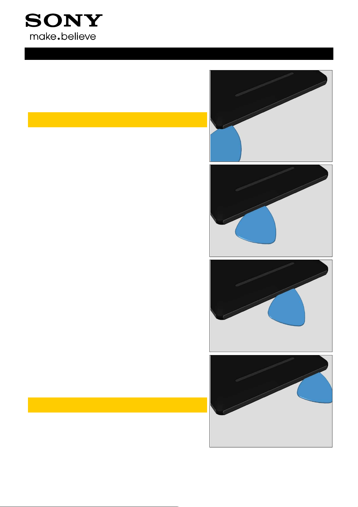
Do the same for this hook.
Note! The hooks near Back Cover Assy corners are
tighter, the unsnapping action may repeat some times.
Working Instructions (mech)
Do the same for this hook.
Do the same for this hook.
Be careful! Do not deform the Back Cover Assy near the
Audio Jack hole.
1290-1182 Rev 4
Sony Mobile Communications AB –
9(72)
Company Internal
Disassembly
Do the same for this hook.
Be careful! Do not deform the Back Cover Assy near the
Audio Jack hole.
Do the same for this hook.
Note! The hooks near Back Cover Assy corners are
tighter, the unsnapping action may repeat some times.
Working Instructions (mech)
Note the position of hooks!
Do the same for this hook.
Note! The hooks near Back Cover Assy corners are
tighter, the unsnapping action may repeat some times.
Be careful! Do not deform the Back Cover Assy near the
USB hole.
1290-1182 Rev 4
Sony Mobile Communications AB –
10(72)

Company Internal
Disassembly
Do the same for this hook.
Be careful! Do not deform the Back Cover Assy near the
USB hole.
Use the Flat Screwdriver to get space for inserting the Metal
Plectrum.
Note! Make sure to insert the Flat Screwdriver between
the Back Cover Assy and front frame, and do not detach
the Back Cover Panel from the Back Cover Assy.
Working Instructions (mech)
Note the position of hooks!
Do the same for these 2 hooks.
1290-1182 Rev 4
Sony Mobile Communications AB –
11(72)

Company Internal
Disassembly
Do the same for this hook.
Note! Do not damage the components on the
Power/Side Key FPC when inserting Metal Plectrum and
unsnapping the hook.
Do the same for this hook.
Note! Do not damage the components on the
Power/Side Key FPC when inserting Metal Plectrum and
unsnapping the hook.
Working Instructions (mech)
Do the same for this hook.
Note! Do not damage the components on the Camera
Key FPC when inserting Metal Plectrum and unsnapping
the hook.
Note! The hooks near Back Cover Assy corners are
tighter, the unsnapping action may repeat some times.
Note the position of hooks!
1290-1182 Rev 4
Sony Mobile Communications AB –
12(72)
Company Internal
Disassembly
Do the same for this hook.
Note! The hooks near Back Cover Assy corners are
tighter, the unsnapping action may repeat some times.
Do the same for this hook.
Working Instructions (mech)
Do the same for this hook.
Do the same for this hook.
Note! The hooks near Back Cover Assy corners are
tighter, the unsnapping action may repeat some times.
1290-1182 Rev 4
Sony Mobile Communications AB –
13(72)
Company Internal
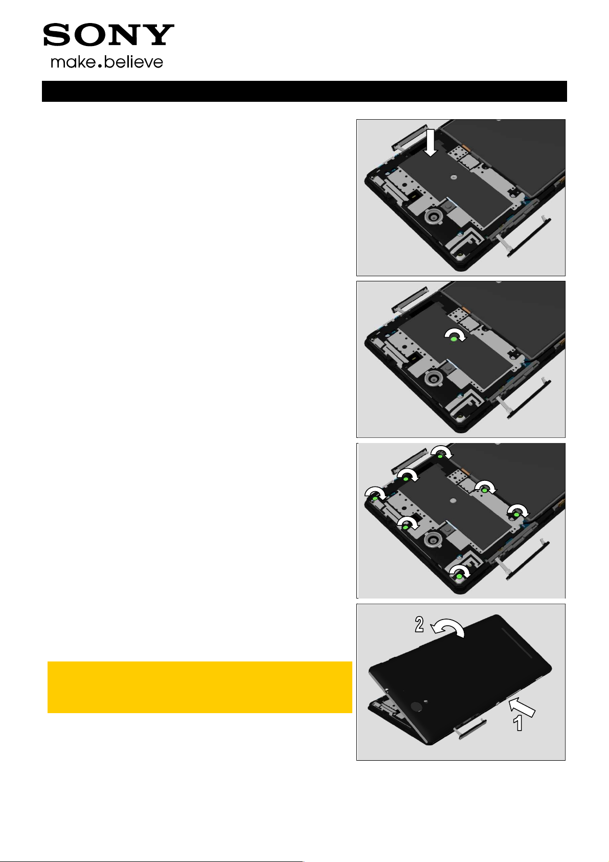
Disassembly
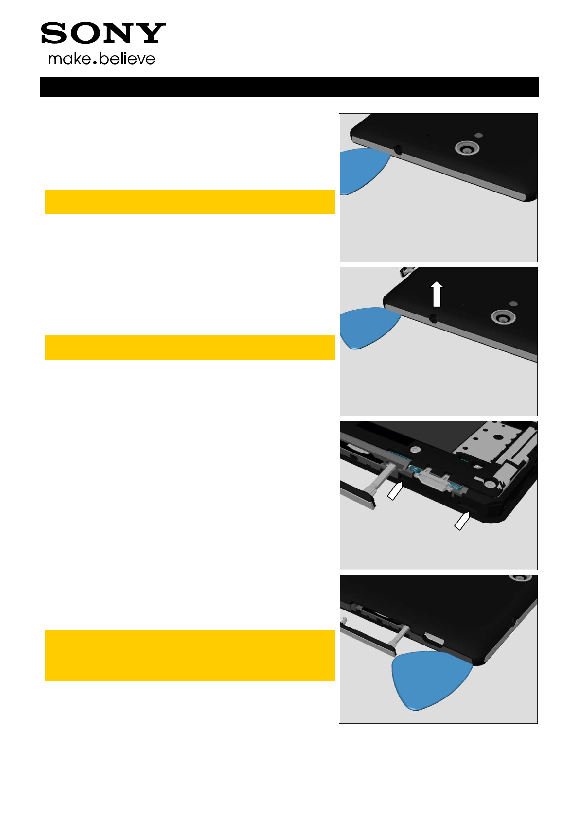
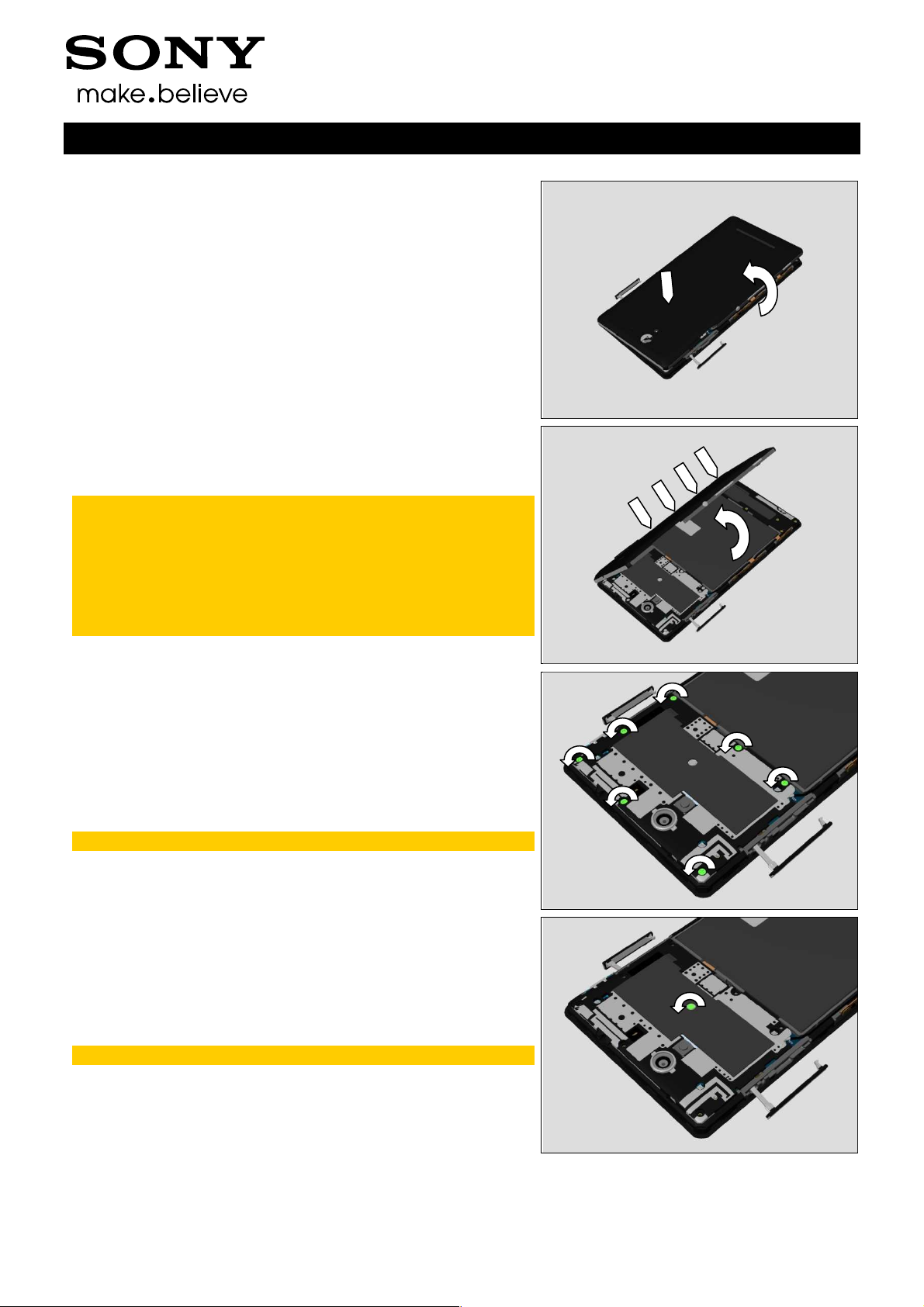
Open the Back Cover Assy as shown in picture to release
the hook in the center.
Unsnap the 4 hooks at the side of Back Cover USB Side
Lower Panel by rotating the Back Cover Assy.
Note! These 4 hooks are tighter than the others, so this
disassembly method has lower possibility of damaging
the Back Cover Assy and front frame than unsnapping
by Metal Plectrum.
This action should not damage the Back Cover Assy
even though it seems the hooks are pretty tight and
more force is applied.
Working Instructions (mech)
3.3 Ant Top Frame Assy
Remove the seven Screw Torx Len:3.1 Diam:1.4 by using a
screwdriver with Bits (JCIS No 0).
Scrap! Not to be reused!
Remove the Screw Other Len:1.1 Diam:1.2 by using a
screwdriver with Bits (JCIS No 0).
Scrap! Not to be reused!
1290-1182 Rev 4
Sony Mobile Communications AB –
14(72)
Company Internal
Disassembly
Release the hooks and lift up the Ant Top Frame Assy.
Remove the Ant Top Frame Assy.
Working Instructions (mech)
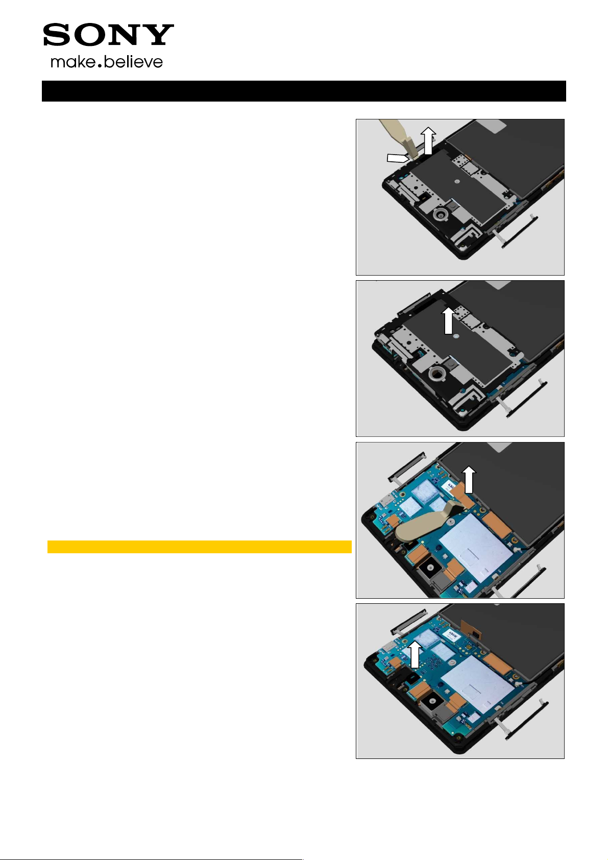
3.4 2nd Mic Rubber
Disconnect the Battery FPC BtB connector.
Do not damage components on the Main PBA!
Remove the 2nd Mic Rubber.
1290-1182 Rev 4
Sony Mobile Communications AB –
15(72)

Company Internal
Disassembly
3.5 Main Camera
Disconnect BtB connector of the Main Camera FPC.
Do not damage components on the Main PBA!
Remove the Main Camera.
Working Instructions (mech)
3.6 Chat Camera
Disconnect BtB connector of the Chat Camera FPC.
Do not damage components on the Main PBA!
Remove the Chat Camera.
1290-1182 Rev 4
Sony Mobile Communications AB –
16(72)
Company Internal
Disassembly
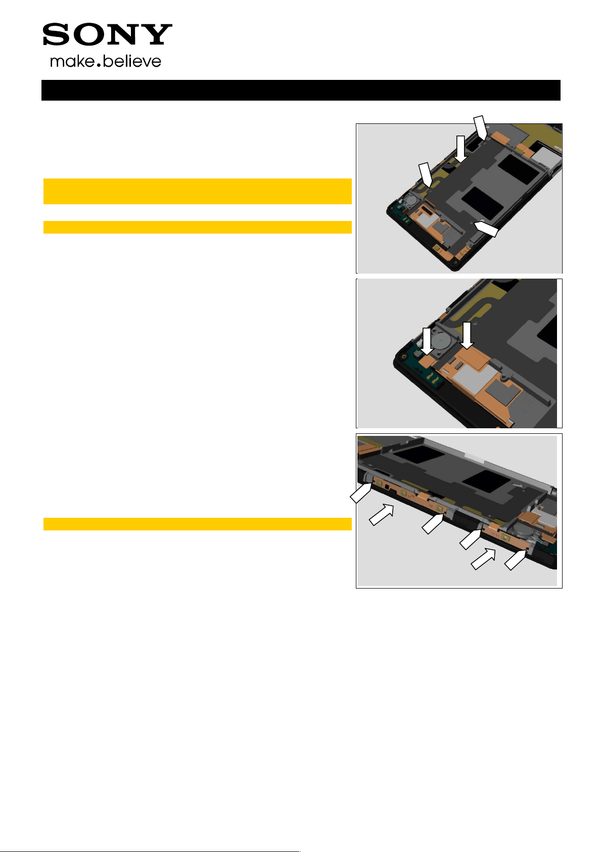
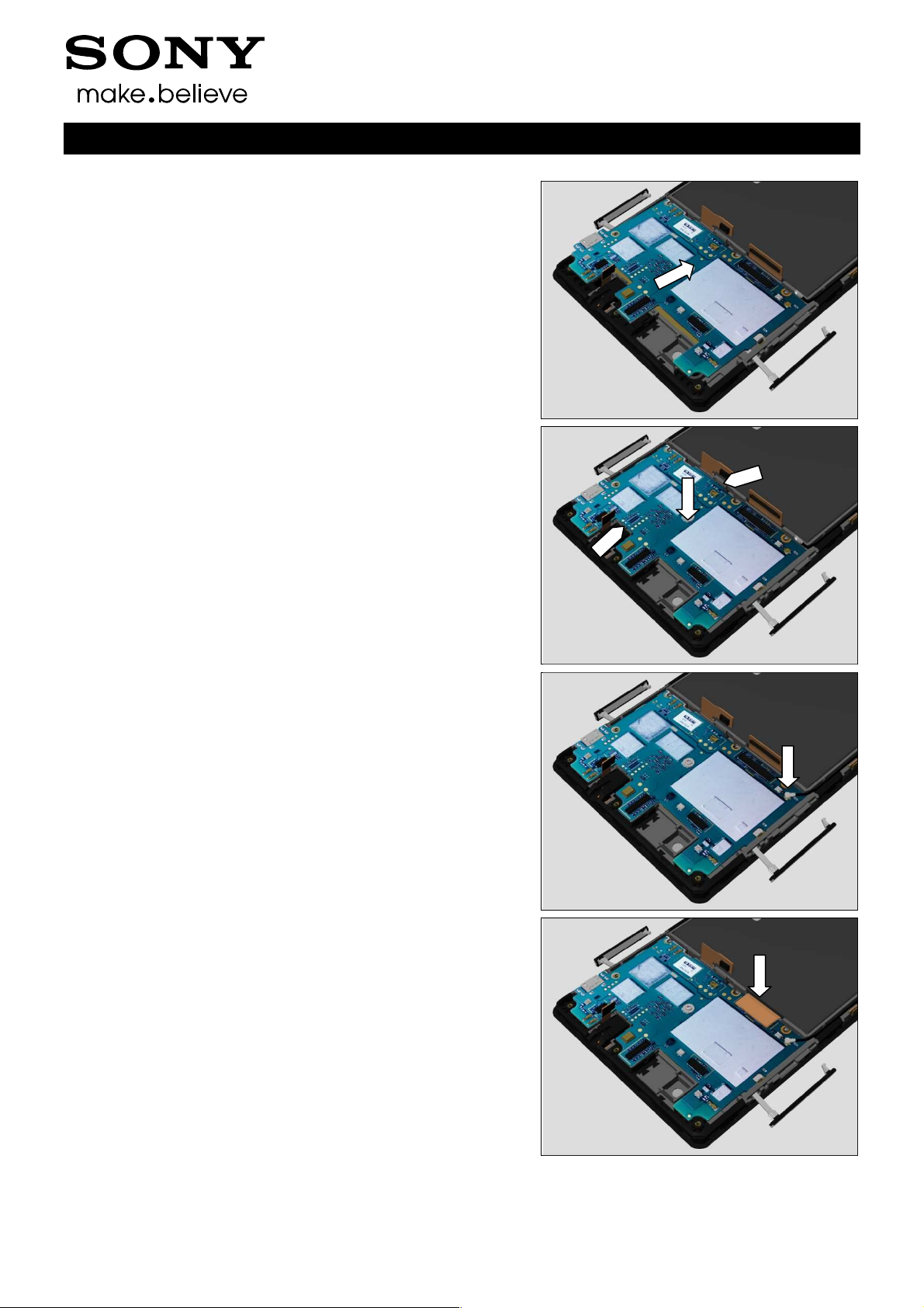
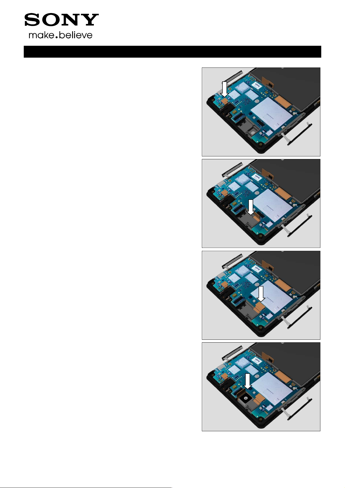
3.7 Main PBA
Disconnect BtB connector of the Audio Jack Assy.
Do not damage components on the Main PBA!
Disconnect BtB connector of the Main FPC Assy.
Do not damage components on the Main PBA!
Working Instructions (mech)
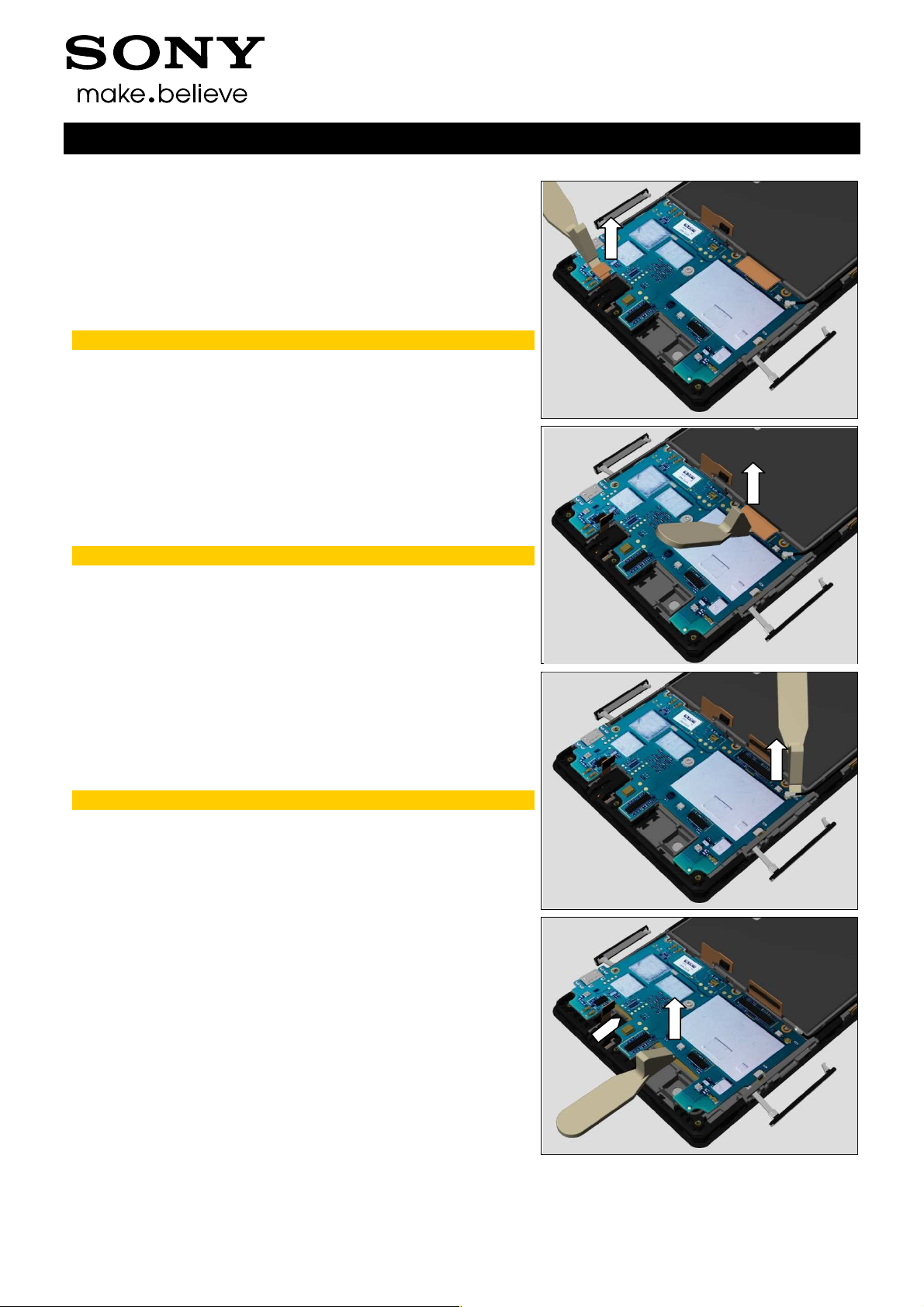
Disconnect RF Cable connector.
Do not damage components on the Main PBA!
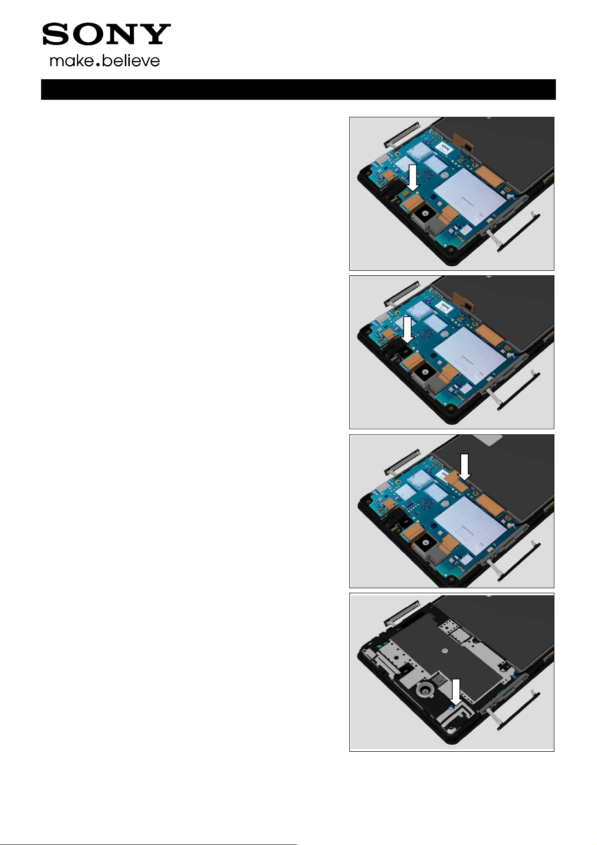
Release the upper side of Main PBA.
1290-1182 Rev 4
Sony Mobile Communications AB –
17(72)
Company Internal
Disassembly
Release the bottom side of Main PBA.
Remove the Main PBA.
Working Instructions (mech)
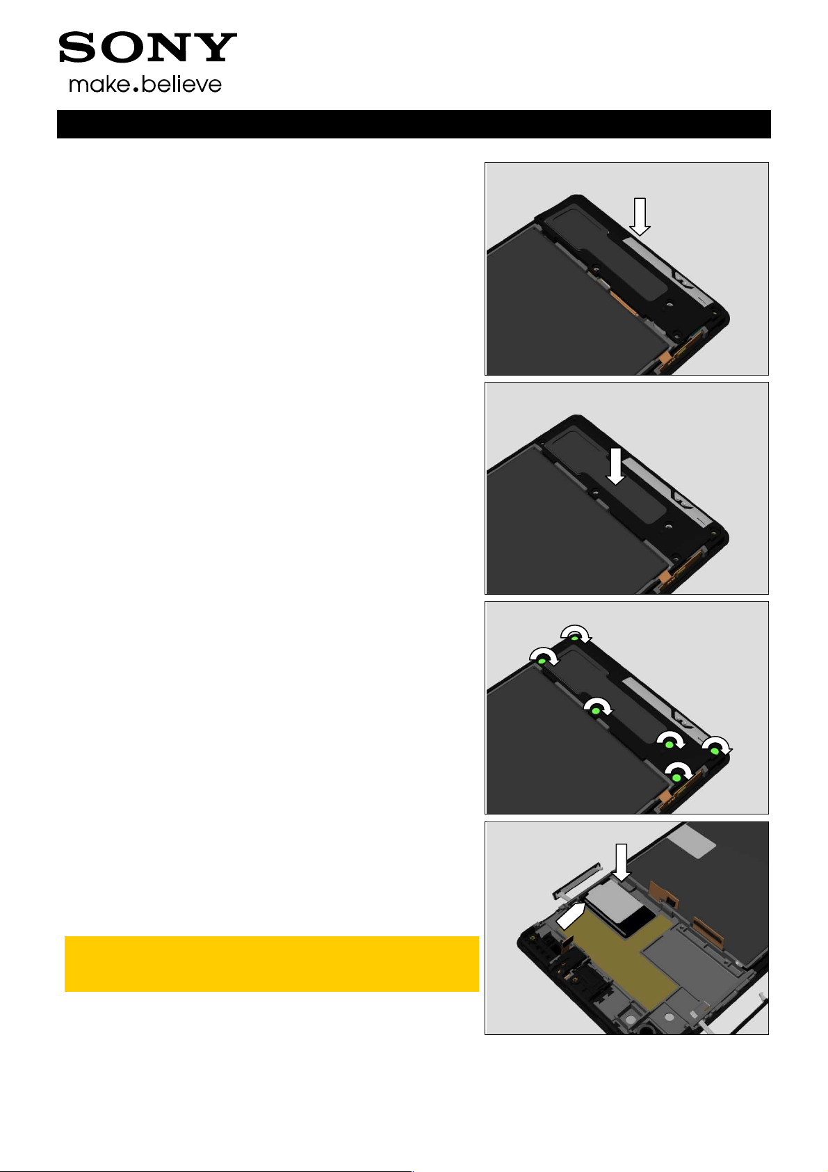
3.8 Core Unit label Tray
Remove the Core Unit label Tray.
3.9 Ant Speaker Bottom
Frame Assy (a) and Display
Frame Assy (b)
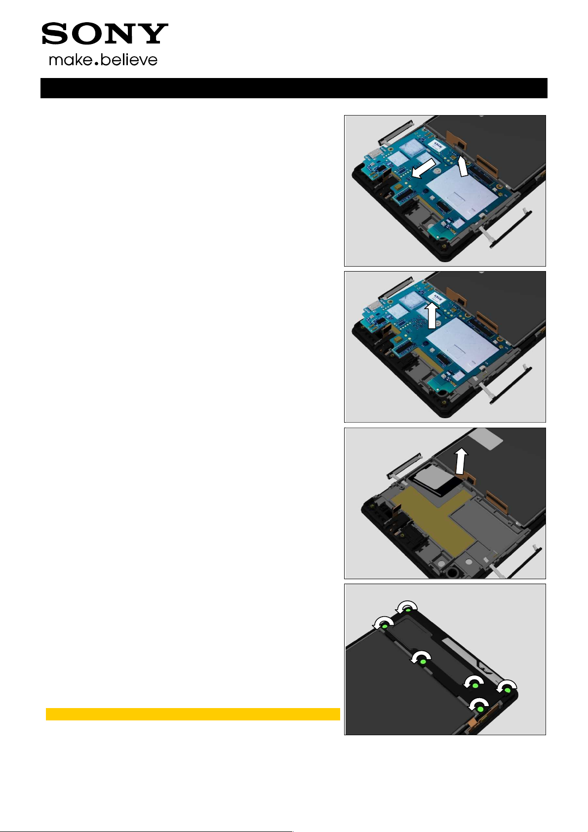
Remove the six Screw M1.4x2.8 by using a screwdriver with
Bits (JCIS No 0).
Scrap! Not to be reused!
1290-1182 Rev 4
Sony Mobile Communications AB –
18(72)
Company Internal
Disassembly
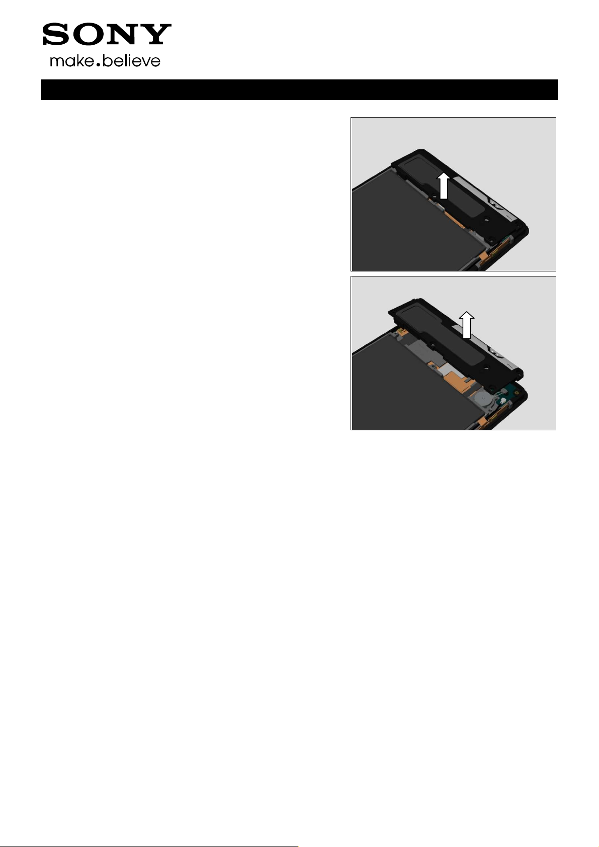
Release the Ant Speaker Bottom Frame Assy.
Remove the Ant Speaker Bottom Frame Assy.
Working Instructions (mech)
1290-1182 Rev 4
Sony Mobile Communications AB –
19(72)
Company Internal
4 Replacement
4.1 2nd Mic Rubber
Follow the 3.2 – 3.4 Disassembly instructions!
Prepare a new 2nd Mic Rubber.
Follow the 5.6 – 5.8 Reassembly instructions!
4.2 Ant Speaker Bottom
Frame Assy
Follow the 3.2 and 3.9 Disassembly instructions!
Prepare a new Ant Speaker Bottom Frame Assy.
Follow the 5.1 and 5.8 Reassembly instructions!
Working Instructions (mech)
4.3 Ant Top Frame Assy
Follow the 3.2 – 3.3 Disassembly instructions!
Prepare a new Ant Top Frame Assy.
Follow the 5.7 – 5.8 Reassembly instructions!
4.4 Back Cover Assy
Follow the 3.2 Disassembly instructions!
Prepare a new Back Cover Assy.
Follow the 5.8 Reassembly instructions!
1290-1182 Rev 4
Sony Mobile Communications AB –
20(72)
Company Internal
Replacement
4.5 Chat Camera
Follow the 3.2 – 3.3 and 3.6 Disassembly instructions!
Prepare a new Chat Camera.
Follow the 4.32 Installation instructions!
Follow the 5.4 and 5.7 – 5.8 Reassembly instructions!
4.6 Core Unit label Tray
Follow the 3.1 – 3.8 Disassembly instructions!
Prepare a new Camera.
Follow the 4.30 Installation instructions!
Follow the 5.2 – 5.9 Reassembly instructions!
Working Instructions (mech)
4.7 Display Frame Assy
Follow the 3.1 – 3.9 Disassembly instructions!
Follow the 4.17, 4.31, 4.40, 4.41, 4.26, 4.38, 4.45 and 4.44
Removal instructions!
Prepare a new Display Frame Assy.
Follow the 4.16, 4.17, 4.31, 4.40, 4.41, 4.33, 4.44, 4.45, 4.38,
4.35 and 4.26 Installation instructions!
Follow the 5.1 – 5.9 Reassembly instructions!
Touch Panel Calibration must be performed for all
replaced units; 1289-2983 Trouble Shooting Application
– mechanical.
4.8 Main Camera
Follow the 3.2 – 3.3 and 3.5 Disassembly instructions!
Prepare a new Main Camera.
Follow the 4.34 Installation instructions!
Follow the 5.5 and 5.7 – 5.8 Reassembly instructions!
1290-1182 Rev 4
Sony Mobile Communications AB –
21(72)
Company Internal
Replacement
4.9 SIM Tray
Follow the 3.1 Disassembly instructions!
Prepare a new SIM Tray.
Follow the 5.9 Reassembly instructions!
Working Instructions (mech)
1290-1182 Rev 4
Sony Mobile Communications AB –
22(72)
Company Internal
Replacement
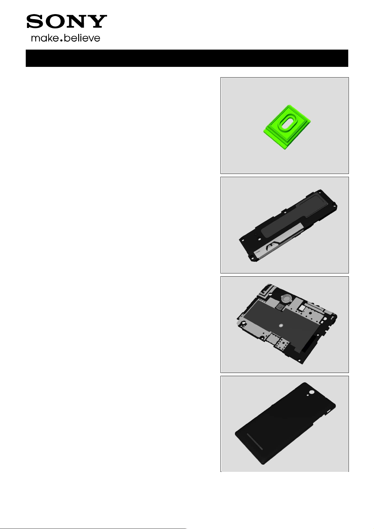
4.10 2nd Mic Mesh
Follow the 3.2 Disassembly instructions!
Prepare a new 2nd Mic Mesh.
Follow the 5.8 Reassembly instructions!
REMOVAL
Detach the 2nd Mic Mesh and remove it with a pair of Plastic
Tweezers.
Scrap! Not to be reused!
Make sure all remaining adhesive residue have been
removed!
Working Instructions (mech)
INSTALLATION
Attach a new 2nd Mic Mesh by using a pair of Plastic
Tweezers as shown in picture and press it.
1290-1182 Rev 4
Sony Mobile Communications AB –
23(72)
Company Internal
Replacement
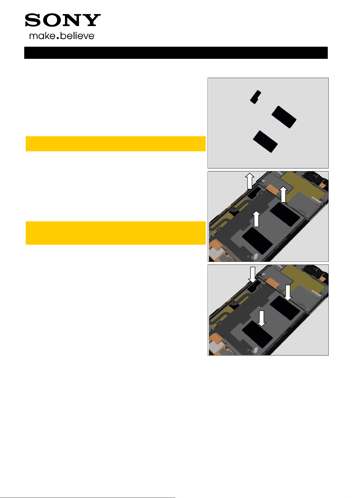
4.11 Adhesive Battery
Follow the 3.1 – 3.9 Disassembly instructions!
Follow the 4.26 Removal instructions!
Prepare a new Adhesive Battery.
Follow the 4.26 Installation instructions!
Follow the 5.1 – 5.9 Reassembly instructions!
Adhesive Battery must be replaced when the Battery is
disassembled.
REMOVAL
Detach the Adhesive Battery and remove it with a pair of
Plastic Tweezers.
Scrap! Not to be reused!
Make sure all remaining adhesive residue have been
removed!
Working Instructions (mech)
INSTALLATION
Attach a new Adhesive Battery by using a pair of Plastic
Tweezers as shown in picture and press it.
1290-1182 Rev 4
Sony Mobile Communications AB –
24(72)
Company Internal
Replacement
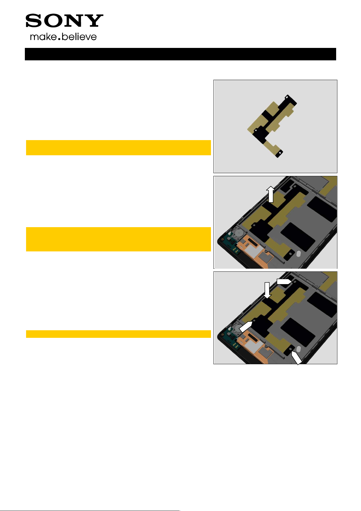
4.12 Adhesive Conductive Main FPC
Follow the 3.1 – 3.9 Disassembly instructions!
Follow the 4.26 and 4.35 Removal instructions!
Prepare a new Adhesive Conductive Main FPC.
Follow the 4.35 and 4.26 Installation instructions!
Follow the 5.1 – 5.9 Reassembly instructions!
Adhesive Conductive Main FPC must be replaced when
the Main FPC Assy is disassembled.
REMOVAL
Detach the Adhesive Conductive Main FPC and remove it
with a pair of Plastic Tweezers.
Scrap! Not to be reused!
Make sure all remaining adhesive residue have been
removed!
Working Instructions (mech)
INSTALLATION
Attach a new Adhesive Conductive Main FPC by using a pair
of Plastic Tweezers as shown in picture and press it.
Note the position of 3 alignment holes!
1290-1182 Rev 4
Sony Mobile Communications AB –
25(72)

Company Internal
Replacement
4.13 Adhesive Conductive Sub PBA
Follow the 3.2 and 3.9 Disassembly instructions!
Follow the 4.44 Removal instructions!
Prepare a new Adhesive Conductive Sub PBA.
Follow the 4.44 Installation instructions!
Follow the 5.1 and 5.8 Reassembly instructions!
Adhesive Conductive Sub PBA must be replaced when
the Sub PBA is disassembled.
REMOVAL
Detach the Adhesive Conductive Sub PBA and remove it with
a pair of Plastic Tweezers.
Scrap! Not to be reused!
Make sure all remaining adhesive residue have been
removed!
Working Instructions (mech)
INSTALLATION
Attach a new Adhesive Conductive Sub PBA by using a pair
of Plastic Tweezers as shown in picture and press it.
1290-1182 Rev 4
Sony Mobile Communications AB –
26(72)

Company Internal
Working Instructions (mech)
Replacement
4.14 Adhesive Conductive Vibrator
Follow the 3.2 and 3.9 Disassembly instructions!
Follow the 4.45 Removal instructions!
Prepare a new Adhesive Conductive Vibrator.
Follow the 4.45 Installation instructions!
Follow the 5.1 and 5.8 Reassembly instructions!
Adhesive Conductive Vibrator must be replaced when
the Vibrator is disassembled.
REMOVAL
Detach the Adhesive Conductive Vibrator and remove it with
a pair of Plastic Tweezers.
Scrap! Not to be reused!
Make sure all remaining adhesive residue have been
removed!
INSTALLATION
Attach a new Adhesive Conductive Vibrator by using a pair
of Plastic Tweezers as shown in picture and press it.
1290-1182 Rev 4
Sony Mobile Communications AB –
27(72)

Company Internal
Working Instructions (mech)
Replacement:
4.15 Adhesive Earspeaker
Follow the 3.1 – 3.7 Disassembly instructions!
Follow the 4.31 Removal instructions!
Prepare a new Adhesive Earspeaker.
Follow the 4.31 Installation instructions!
Follow the 5.3 – 5.9 Reassembly instructions!
Adhesive Earspeaker must be replaced when the
Earspeaker is disassembled.
REMOVAL
Detach the Adhesive Earspeaker and remove it with a pair of
Plastic Tweezers.
Scrap! Not to be reused!
Make sure all remaining adhesive residue have been
removed!
INSTALLATION
Attach a new Adhesive Earspeaker by using a pair of Plastic
Tweezers as shown in picture and press it.
1290-1182 Rev 4
Sony Mobile Communications AB –
28(72)

Company Internal
Working Instructions (mech)
Replacement
4.16 Audio Jack Adhesive
Follow the 3.1 – 3.7 Disassembly instructions!
Follow the 4.17 Removal instructions!
Prepare a new Audio Jack Adhesive.
Follow the 4.17 Installation instructions!
Follow the 5.3 – 5.9 Reassembly instructions!
Audio Jack Adhesive must be replaced when the Audio
Jack Assy is disassembled.
REMOVAL
Detach the Audio Jack Adhesive and remove it with a pair of
Plastic Tweezers.
Scrap! Not to be reused!
Make sure all remaining adhesive residue on the Audio
Jack Assy and front frame have been removed!
INSTALLATION
Attach a new Audio Jack Adhesive by using a pair of Plastic
Tweezers as shown in picture and press it.
1290-1182 Rev 4
Sony Mobile Communications AB –
29(72)

Company Internal
Replacement
4.17 Audio Jack Assy
Follow the 3.1 – 3.7 Disassembly instructions!
Prepare a new Audio Jack Assy.
Follow the 5.3 – 5.9 Reassembly instructions!
REMOVAL
Detach the Audio Jack Assy to remove it.
Make sure all remaining adhesive residue on the front
frame have been removed!
Working Instructions (mech)
INSTALLATION
Follow the 4.18 Removal and Installation instructions to
replace a new Audio Jack Film.
Mount the Audio Jack Assy in its cavity and press it.
1290-1182 Rev 4
Sony Mobile Communications AB –
30(72)

Company Internal
Replacement
4.18 Audio Jack Film
Follow the 3.1 – 3.7 Disassembly instructions!
Follow the 4.17 Removal instructions!
Prepare a new Audio Jack Film.
Follow the 4.17 Installation instructions!
Follow the 5.3 – 5.9 Reassembly instructions!
Audio Jack Film must be replaced when the Audio Jack
Assy is replaced.
REMOVAL
Detach the Audio Jack Film and remove it with a pair of
Plastic Tweezers.
Scrap! Not to be reused!
Make sure all remaining adhesive residue have been
removed!
Working Instructions (mech)
INSTALLATION
Attach a new Audio Jack Film by using a pair of Plastic
Tweezers as shown in picture and press it.
1290-1182 Rev 4
Sony Mobile Communications AB –
31(72)
Company Internal
Working Instructions (mech)
Replacement
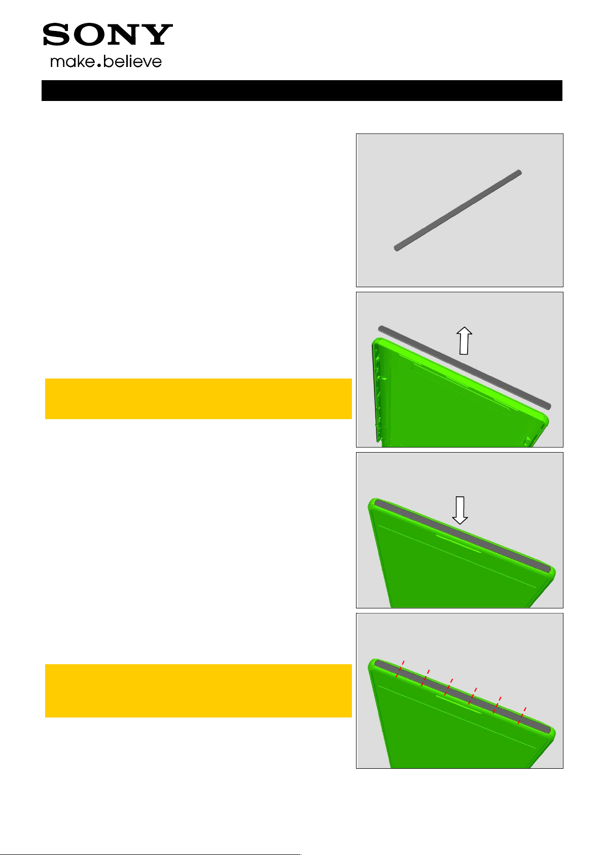
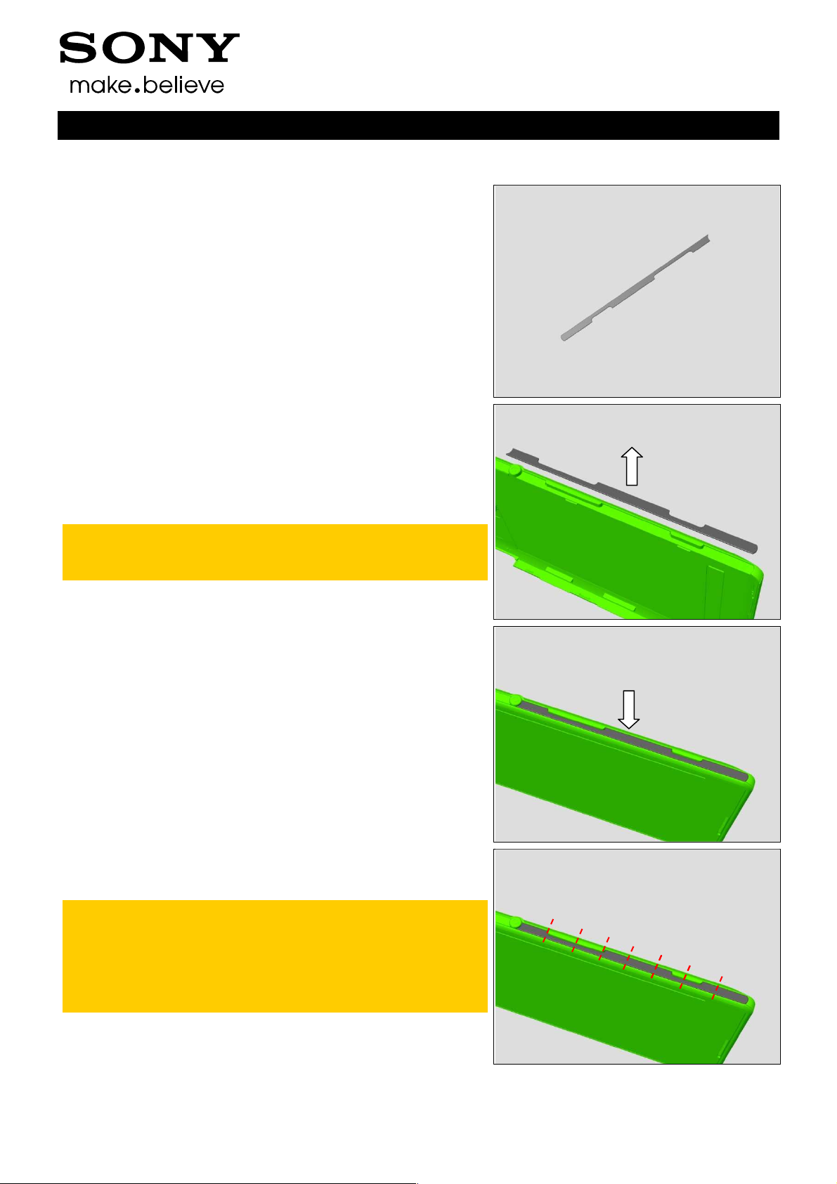
4.19 Back Cover Bottom Panel
Follow the 3.2 Disassembly instructions!
Prepare a new Back Cover Bottom Panel.
Follow the 5.8 Reassembly instructions!
REMOVAL
Disassemble the Back Cover Assy.
Detach the Back Cover Bottom Panel.
Scrap! Not to be reused!
Make sure all remaining adhesive residue have been
removed!
INSTALLATION
Assemble the Back Cover Assy.
Attach the Back Cover Bottom Panel into its cavity as shown
in picture.
Press it hard by finger from one side to the other side
part by part, press each part for 5s.
The panel is divided into 7 parts whose length is about 1
centimeter.
1290-1182 Rev 4
Sony Mobile Communications AB –
32(72)
Company Internal
Working Instructions (mech)
Replacement
4.20 Back Cover Sidekey Side Lower Panel
Follow the 3.2 Disassembly instructions!
Prepare a new Back Cover Sidekey Side Lower Panel.
Follow the 5.8 Reassembly instructions!
REMOVAL
Disassemble the Back Cover Assy.
Detach the Back Cover Sidekey Side Lower Panel.
Scrap! Not to be reused!
Make sure all remaining adhesive residue have been
removed!
INSTALLATION
Assemble the Back Cover Assy.
Attach the Back Cover Sidekey Side Lower Panel into its
cavity as shown in picture.
Press it hard by finger from one side to the other side
part by part, press each part for 5s.
The panel is divided into 8 parts whose length is about 1
centimeter.
Check the function of Power key, Side key and Camera
key after pressing.
1290-1182 Rev 4
Sony Mobile Communications AB –
33(72)
Company Internal
Working Instructions (mech)
Replacement
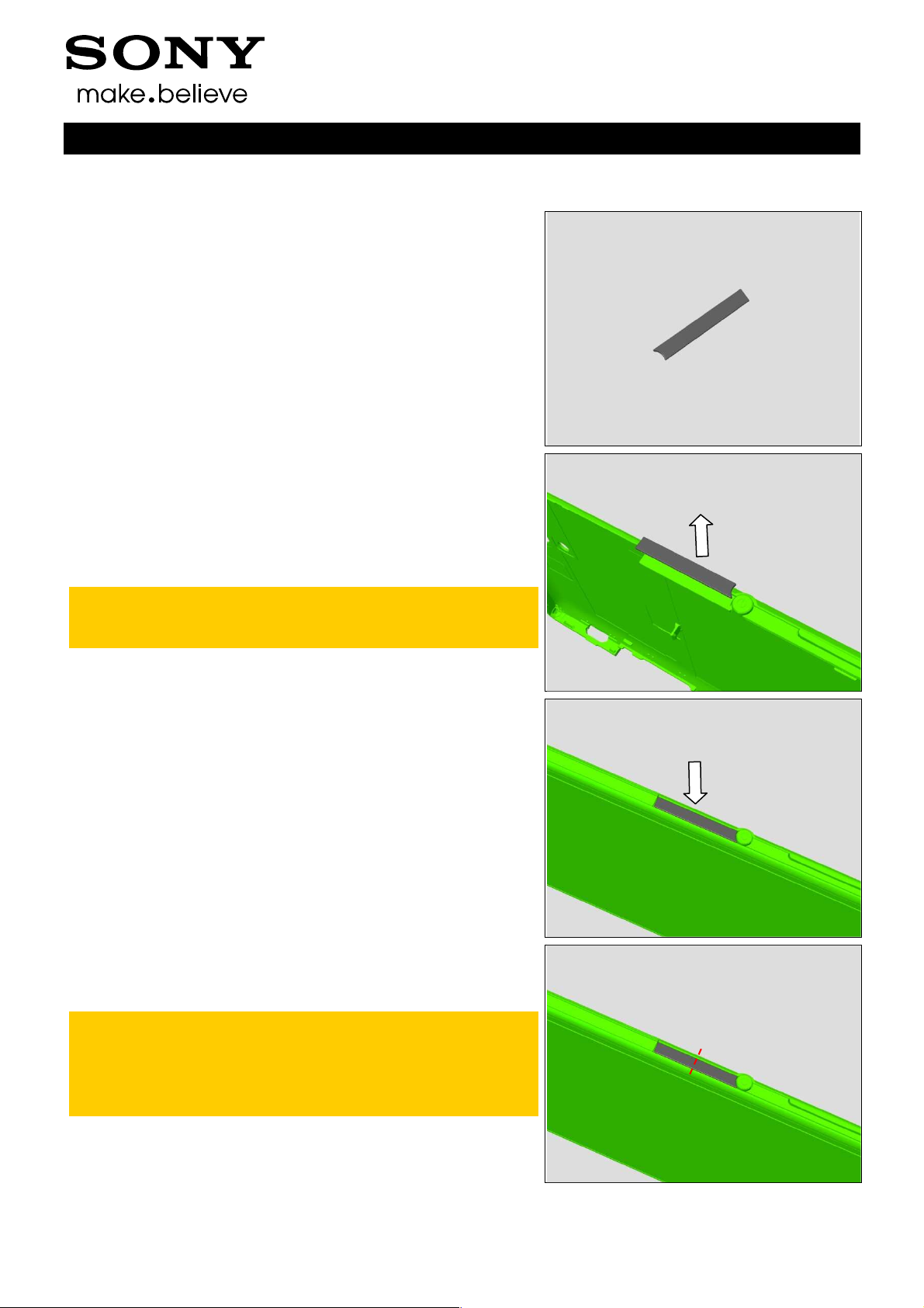
4.21 Back Cover Sidekey Side Middle Panel
Follow the 3.2 Disassembly instructions!
Prepare a new Back Cover Sidekey Side Middle Panel.
Follow the 5.8 Reassembly instructions!
REMOVAL
Disassemble the Back Cover Assy.
Detach the Back Cover Sidekey Side Middle Panel.
Scrap! Not to be reused!
Make sure all remaining adhesive residue have been
removed!
INSTALLATION
Assemble the Back Cover Assy.
Attach the Back Cover Sidekey Side Middle Panel into its
cavity as shown in picture.
Press it hard by finger from one side to the other side
part by part, press each part for 5s.
The panel is divided into 2 parts whose length is about 1
centimeter.
Check the function of Power key after pressing.
1290-1182 Rev 4
Sony Mobile Communications AB –
34(72)

Company Internal
Working Instructions (mech)
Replacement
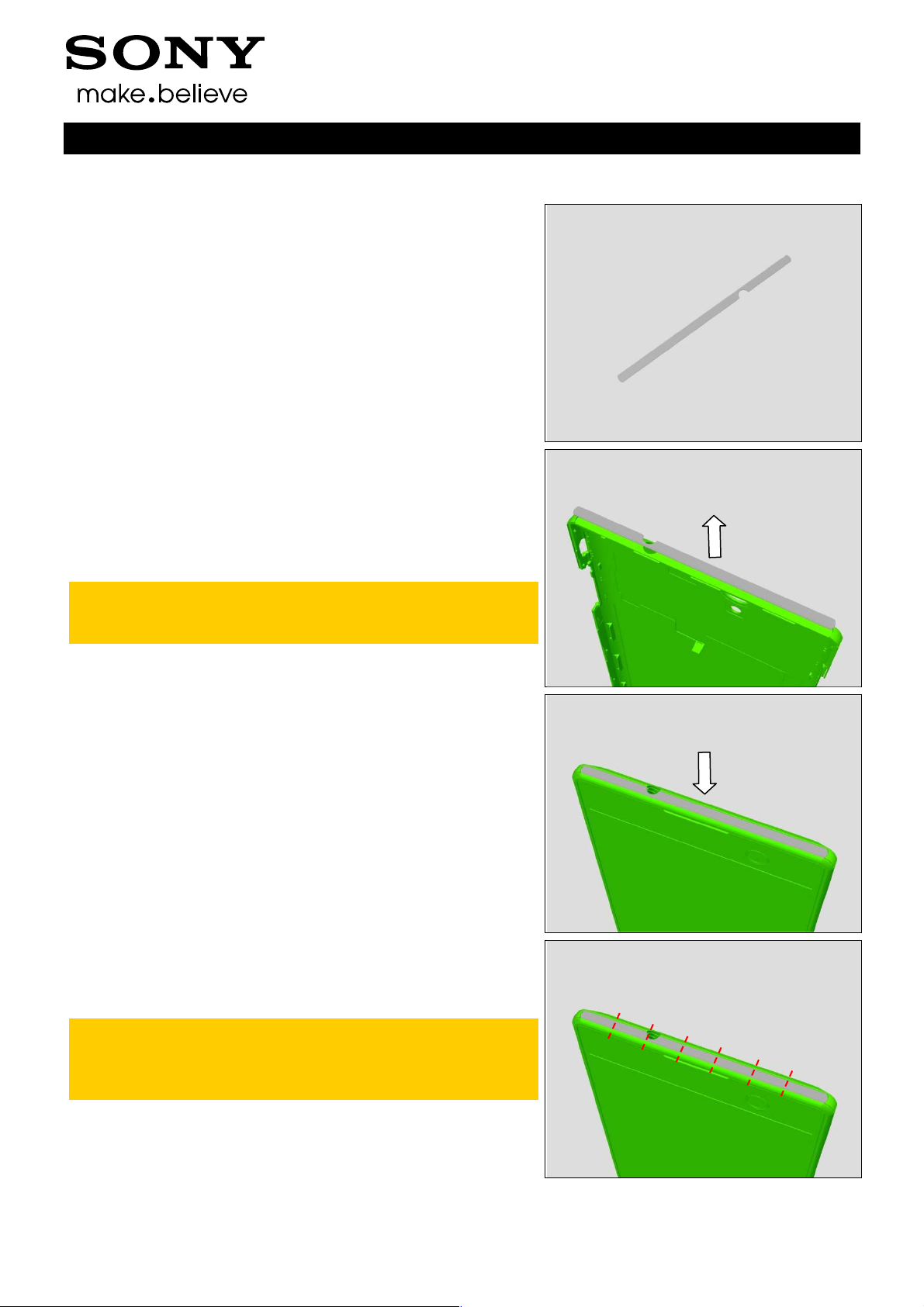
4.22 Back Cover Sidekey Side Upper Panel
Follow the 3.2 Disassembly instructions!
Prepare a new Back Cover Sidekey Side Upper Panel.
Follow the 5.8 Reassembly instructions!
REMOVAL
Disassemble the Back Cover Assy.
Detach the Back Cover Sidekey Side Upper Panel.
Scrap! Not to be reused!
Make sure all remaining adhesive residue have been
removed!
INSTALLATION
Assemble the Back Cover Assy.
Attach the Back Cover Sidekey Side Upper Panel into its
cavity as shown in picture.
Press it hard by finger from one side to the other side
part by part, press each part for 5s.
The panel is divided into 2 parts whose length is about 1
centimeter.
1290-1182 Rev 4
Sony Mobile Communications AB –
35(72)
Company Internal
Replacement
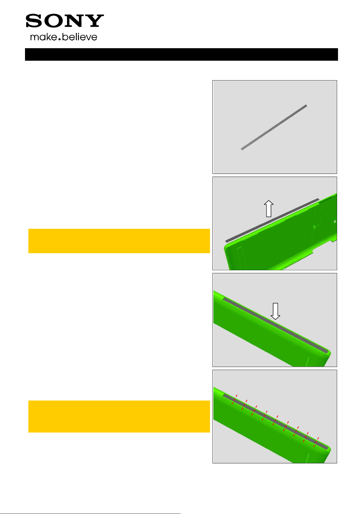
4.23 Back Cover Top Panel
Follow the 3.2 Disassembly instructions!
Prepare a new Back Cover Top Panel.
Follow the 5.8 Reassembly instructions!
REMOVAL
Disassemble the Back Cover Assy.
Detach the Back Cover Top Panel.
Scrap! Not to be reused!
Make sure all remaining adhesive residue have been
removed!
Working Instructions (mech)
INSTALLATION
Assemble the Back Cover Assy.
Attach the Back Cover Top Panel into its cavity as shown in
picture.
Press it hard by finger from one side to the other side
part by part, press each part for 5s.
The panel is divided into 7 parts whose length is about 1
centimeter.
1290-1182 Rev 4
Sony Mobile Communications AB –
36(72)
Company Internal
Working Instructions (mech)
Replacement
4.24 Back Cover USB Side Lower Panel
Follow the 3.2 Disassembly instructions!
Prepare a new Back Cover USB Side Lower Panel.
Follow the 5.8 Reassembly instructions!
REMOVAL
Disassemble the Back Cover Assy.
Detach the Back Cover USB Side Lower Panel.
Scrap! Not to be reused!
Make sure all remaining adhesive residue have been
removed!
INSTALLATION
Assemble the Back Cover Assy.
Attach the Back Cover USB Side Lower Panel into its cavity
as shown in picture.
Press it hard by finger from one side to the other side
part by part, press each part for 5s.
The panel is divided into 10 parts whose length is about
1 centimeter.
1290-1182 Rev 4
Sony Mobile Communications AB –
37(72)
Company Internal
Working Instructions (mech)
Replacement
4.25 Back Cover USB Side Upper Panel
Follow the 3.2 Disassembly instructions!
Prepare a new Back Cover USB Side Upper Panel.
Follow the 5.8 Reassembly instructions!
REMOVAL
Disassemble the Back Cover Assy.
Detach the Back Cover USB Side Upper Panel.
Scrap! Not to be reused!
Make sure all remaining adhesive residue have been
removed!
INSTALLATION
Assemble the Back Cover Assy.
Attach the Back Cover USB Side Upper Panel into its cavity
as shown in picture.
Press it hard by finger from one side to the other side
part by part, press each part for 5s.
The panel is divided into 2 parts whose length is about 1
centimeter.
1290-1182 Rev 4
Sony Mobile Communications AB –
38(72)

Company Internal
Working Instructions (mech)
Replacement
4.26 Battery
Follow the 3.1 – 3.9 Disassembly instructions!
Follow the 4.11 and 4.27 Removal instructions!
Prepare a new Battery.
Follow the 4.11 and 4.27 Installation instructions!
Follow the 5.1 – 5.9 Reassembly instructions!
REMOVAL
Turn the Battery Release Tape vertically.
Pull the tape to release the Battery from its adhesive
underneath.
Scrap! Not to be reused!
INSTALLATION
Follow the 4.11 and 4.27 Removal and Installation
instructions to replace a new Adhesive Battery and a
new Battery Release Tape.
Mount the Battery into its cavity.
Press the Battery hard by fingers onto the adhesive area for
5s separately.
1290-1182 Rev 4
Sony Mobile Communications AB –
39(72)
Company Internal
Working Instructions (mech)
Replacement
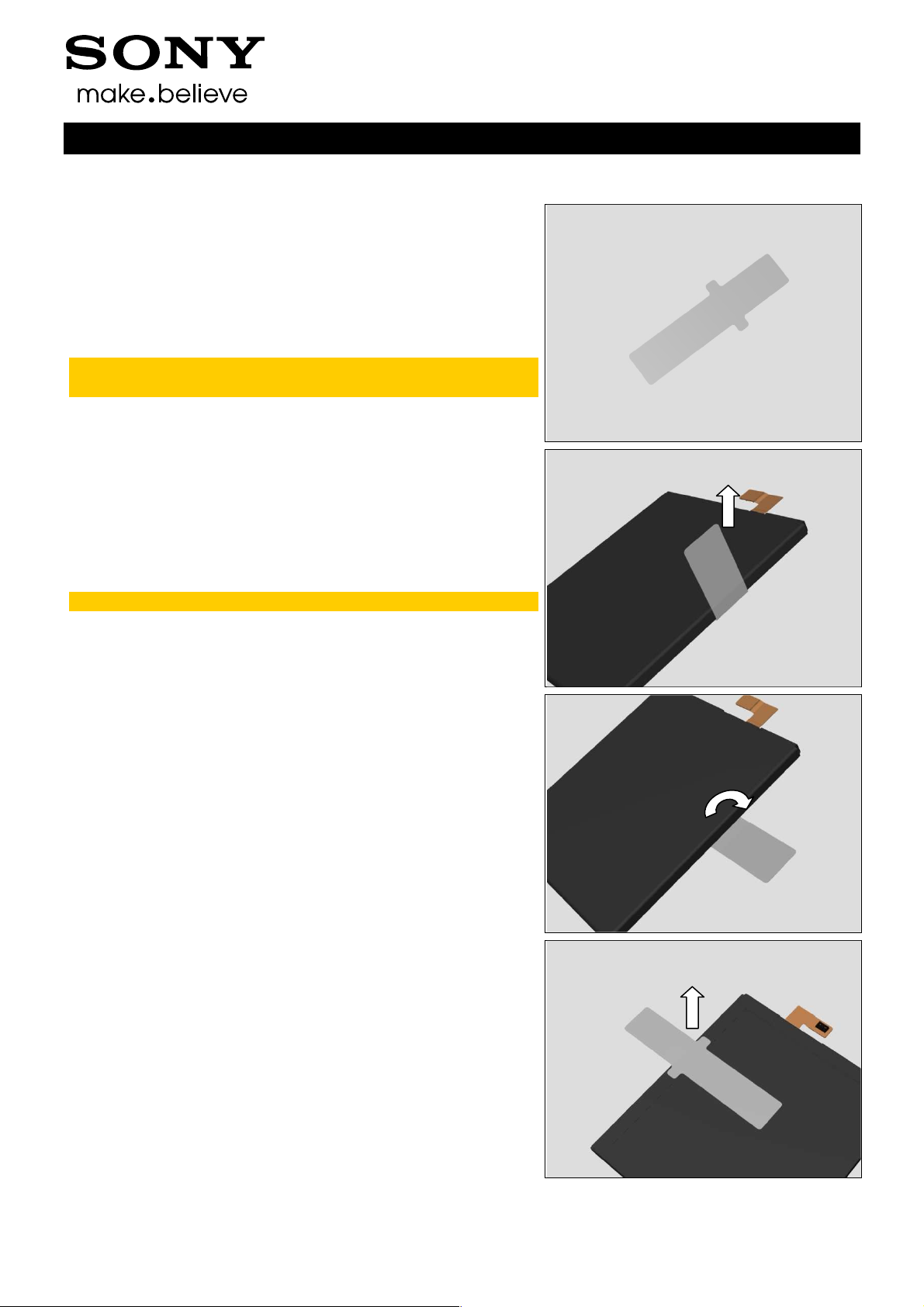
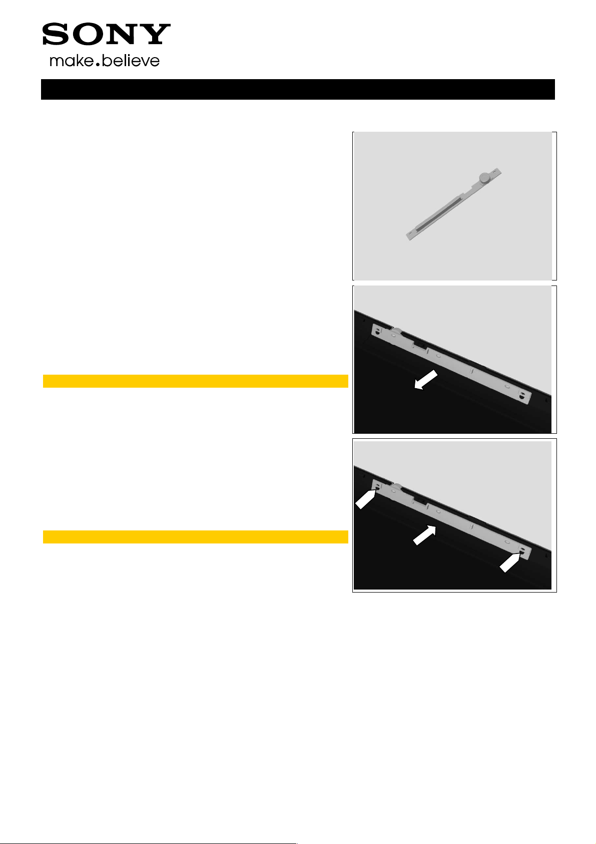
4.27 Battery Release Tape
Follow the 3.1 – 3.9 Disassembly instructions!
Follow the 4.26 Removal instructions!
Prepare a new Battery Release Tape.
Follow the 4.26 Installation instructions!
Follow the 5.1 – 5.9 Reassembly instructions!
Battery Release Tape must be replaced when the Battery
is disassembled.
REMOVAL
Detach the Battery Release Tape as shown in picture.
Scrap! Not to be reused!
Do the same.
Do the same.
1290-1182 Rev 4
Sony Mobile Communications AB –
40(72)

Company Internal
Working Instructions (mech)
Replacement: Battery Release Tape
INSTALLATION
Attach the Battery Release Tape in its proper position as
shown in picture.
Attach the rest part of the Battery Release Tape.
Do the same.
1290-1182 Rev 4
Sony Mobile Communications AB –
41(72)

Company Internal
Working Instructions (mech)
Replacement
4.28 Camera Key Assy
Follow the 3.2 Disassembly instructions!
Prepare a new Camera Key Assy.
Follow the 5.8 Reassembly instructions!
REMOVAL
Detach the Camera Key Assy.
Scrap! Not to be reused!
Make sure all remaining adhesive residue have been
removed!
INSTALLATION
Attach the Camera Key Assy and press it.
Note the position of alignment pins and holes!
1290-1182 Rev 4
Sony Mobile Communications AB –
42(72)

Company Internal
Working Instructions (mech)
Replacement
4.29 Camera Window
Follow the 3.2 – 3.3 Disassembly instructions!
Prepare a new Camera Window.
Follow the 5.7 – 5.8 Reassembly instructions!
REMOVAL
Detach the Camera Window.
Scrap! Not to be reused!
Make sure all remaining adhesive residue have been
removed!
INSTALLATION
Attach the Camera Window and press it.
1290-1182 Rev 4
Sony Mobile Communications AB –
43(72)

Company Internal
Replacement
4.30 Core Unit label
Follow the 3.1 – 3.8 Disassembly instructions!
Prepare a new Core Unit label.
Follow the 5.2 – 5.9 Reassembly instructions!
REMOVAL
Read the old Core Unit Label and/or write the information
into the ‘Label Print Solution’ program before removal.
Carefully remove the Core Unit Label by using the Flex Film
Assembly Tool.
Scrap! Not to be reused!
Working Instructions (mech)
INSTALLATION
Check that the label format is properly loaded in the Zebra
printer and write a new Label using the ‘Label Print Solution’
software.
Attach a new Core Unit Label in its proper position as
shown in picture.
Attach a new Core Unit Label in its proper position as
shown in picture.
1290-1182 Rev 4
Sony Mobile Communications AB –
44(72)

Company Internal
Replacement
4.31 Earspeaker
Follow the 3.1 – 3.7 Disassembly instructions!
Prepare a new Earspeaker
Follow the 5.3 – 5.9 Reassembly instructions!
REMOVAL
Detach the Earspeaker.
Note position of applying a pair of Pointed-tip tweezers
as shown in picture!
Be careful! Insert a pair of Pointed-tip tweezers between
the Earspeaker and front frame to detach the
Earspeaker, otherwise the Earspeaker is easy to be
damaged.
Working Instructions (mech)
INSTALLATION
Follow the 4.15 Removal and Installation instructions to
replace a new Adhesive Earspeaker.
Mount the Earspeaker into its cavity.
Note the direction of the Earspeaker!
Press to secure its solid attachment.
1290-1182 Rev 4
Sony Mobile Communications AB –
45(72)

Company Internal
Replacement
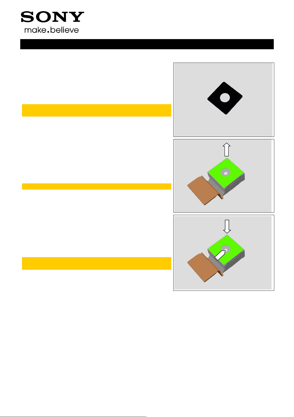
4.32 Gasket Chat Camera
Follow the 3.2 – 3.3 and 3.6 Disassembly instructions!
Prepare a new Gasket Chat Camera.
Follow the 5.4 and 5.7 – 5.8 Reassembly instructions!
Gasket Chat Camera must be replaced when the Chat
Camera is replaced.
REMOVAL
Detach the Gasket Chat Camera.
Scrap! Not to be reused!
Working Instructions (mech)
INSTALLATION
Attach the Gasket Chat Camera.
Note position of the Gasket Chat Camera! Make sure the
camera lens is in the center of the circle.
1290-1182 Rev 4
Sony Mobile Communications AB –
46(72)

Company Internal
Working Instructions (mech)
Replacement
4.33 Liquid Indicator
Follow the 3.1 – 3.8 Disassembly instructions!
Prepare a new Liquid Indicator.
Follow the 5.2 – 5.9 Reassembly instructions!
REMOVAL
Detach to remove the Liquid Indicator by using a Flex Film
Assembly Tool.
Scrap! Not to be reused!
INSTALLATION
Attach a new Liquid Indicator in its proper position by using a
Flex Film Assembly Tool as shown in picture.
Note position of the Liquid Indicator! Make sure the
Liquid Indicator is aligned to the top left corner of the rib.
Do the same to this Liquid Indicator.
1290-1182 Rev 4
Sony Mobile Communications AB –
47(72)
Company Internal
Replacement
4.34 Main Camera Film
Follow the 3.2 – 3.3 and 3.5 Disassembly instructions!
Prepare a new Main Camera Film.
Follow the 5.5 and 5.7 – 5.8 Reassembly instructions!
Main Camera Film must be replaced when the Main
Camera is replaced.
REMOVAL
Detach the Main Camera Film.
Scrap! Not to be reused!
Working Instructions (mech)
INSTALLATION
Attach the Main Camera Film.
Note position of the Main Camera Film! Make sure the
camera lens is in the center of the circle.
1290-1182 Rev 4
Sony Mobile Communications AB –
48(72)
Company Internal
Replacement
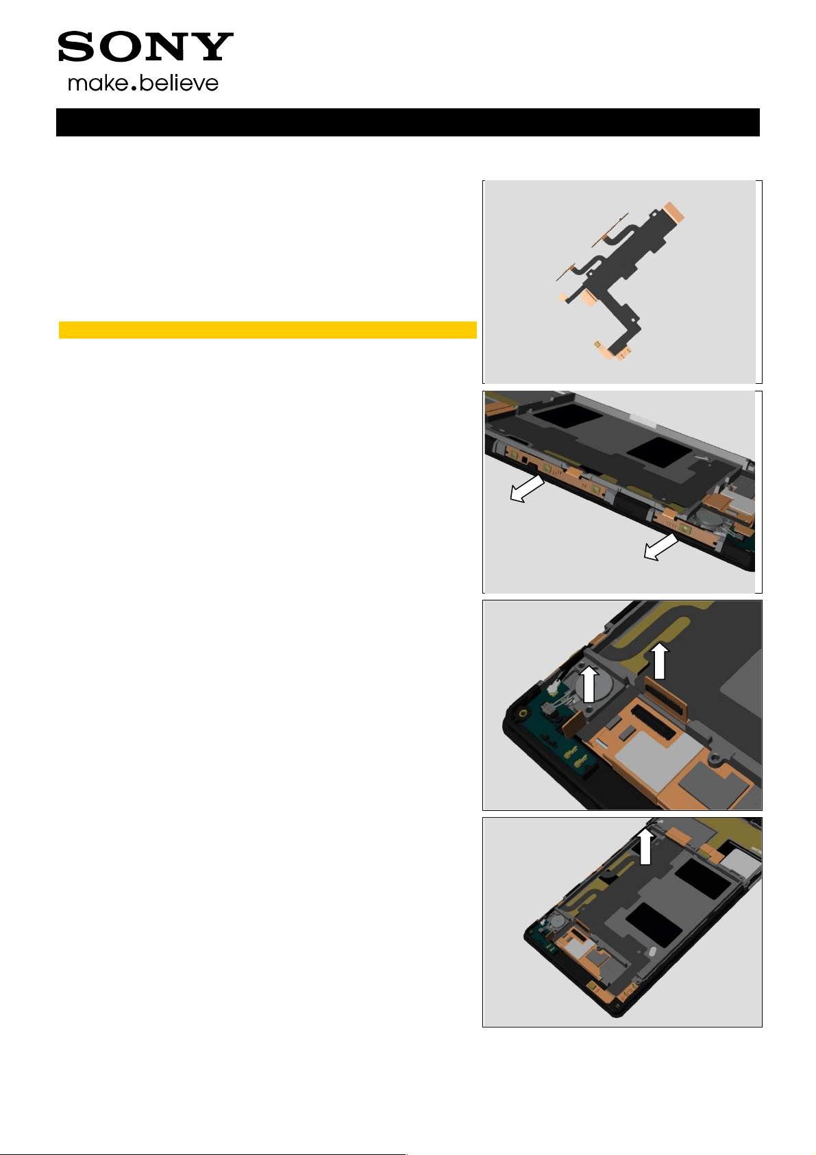
4.35 Main FPC Assy
Follow the 3.1 – 3.9 Disassembly instructions!
Follow the 4.26 Removal instructions!
Prepare a new Main FPC Assy.
Follow the 4.26 Installation instructions!
Follow the 5.1 – 5.9 Reassembly instructions!
Scrap! Not to be reused!
REMOVAL
Detach the power/side key FPC and camera key FPC.
Working Instructions (mech)
Disconnect these 2 BtB connectors.
Detach the Main FPC Assy.
1290-1182 Rev 4
Sony Mobile Communications AB –
49(72)
Company Internal
Replacement: Main FPC Assy
INSTALLATION
Follow the 4.12 Removal and Installation instructions to
replace a new Adhesive Conductive Main FPC.
Attach the Main FPC and press to secure the attachment.
Note position of alignment holes!
Press to snap these 2 BtB connectors.
Working Instructions (mech)
Attach the power/side key FPC and camera key FPC and
press it.
Note position of alignment pins!
1290-1182 Rev 4
Sony Mobile Communications AB –
50(72)
Company Internal
Replacement
4.36 Power/Side Key Assy
Follow the 3.2 Disassembly instructions!
Prepare a new Power/Side Key Assy.
Follow the 5.8 Reassembly instructions!
REMOVAL
Detach the Power/Side Key Assy,
Scrap! Not to be reused!
Working Instructions (mech)
INSTALLATION
Attach the Power/Side Key Assy and press it.
Note position of alignment pins and holes!
1290-1182 Rev 4
Sony Mobile Communications AB –
51(72)
Company Internal
Replacement
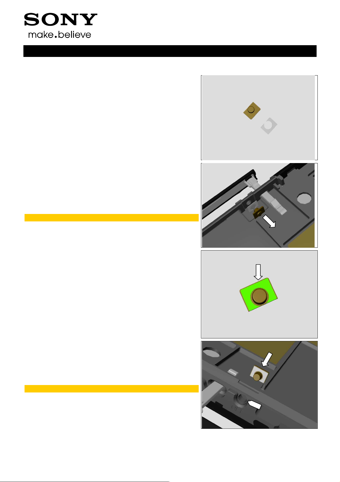
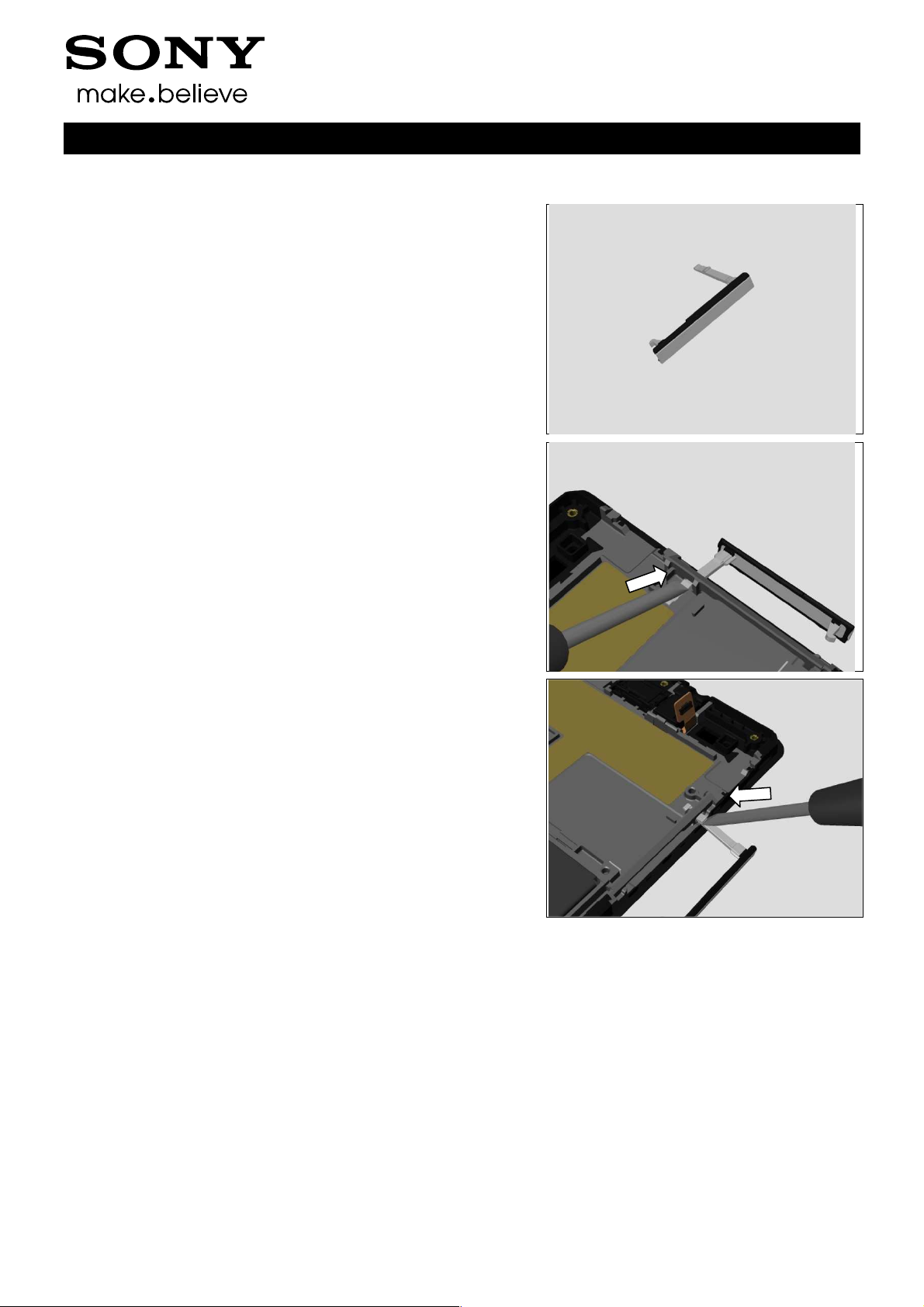
4.37 Reset Key and Tape Reset Key
Follow the 3.1 – 3.7 Disassembly instructions!
Prepare a new Reset Key and Tape Reset Key.
Follow the 5.3 – 5.9 Reassembly instructions!
REMOVAL
Detach Reset Key and Tape Reset Key.
Scrap! Not to be reused!
Working Instructions (mech)
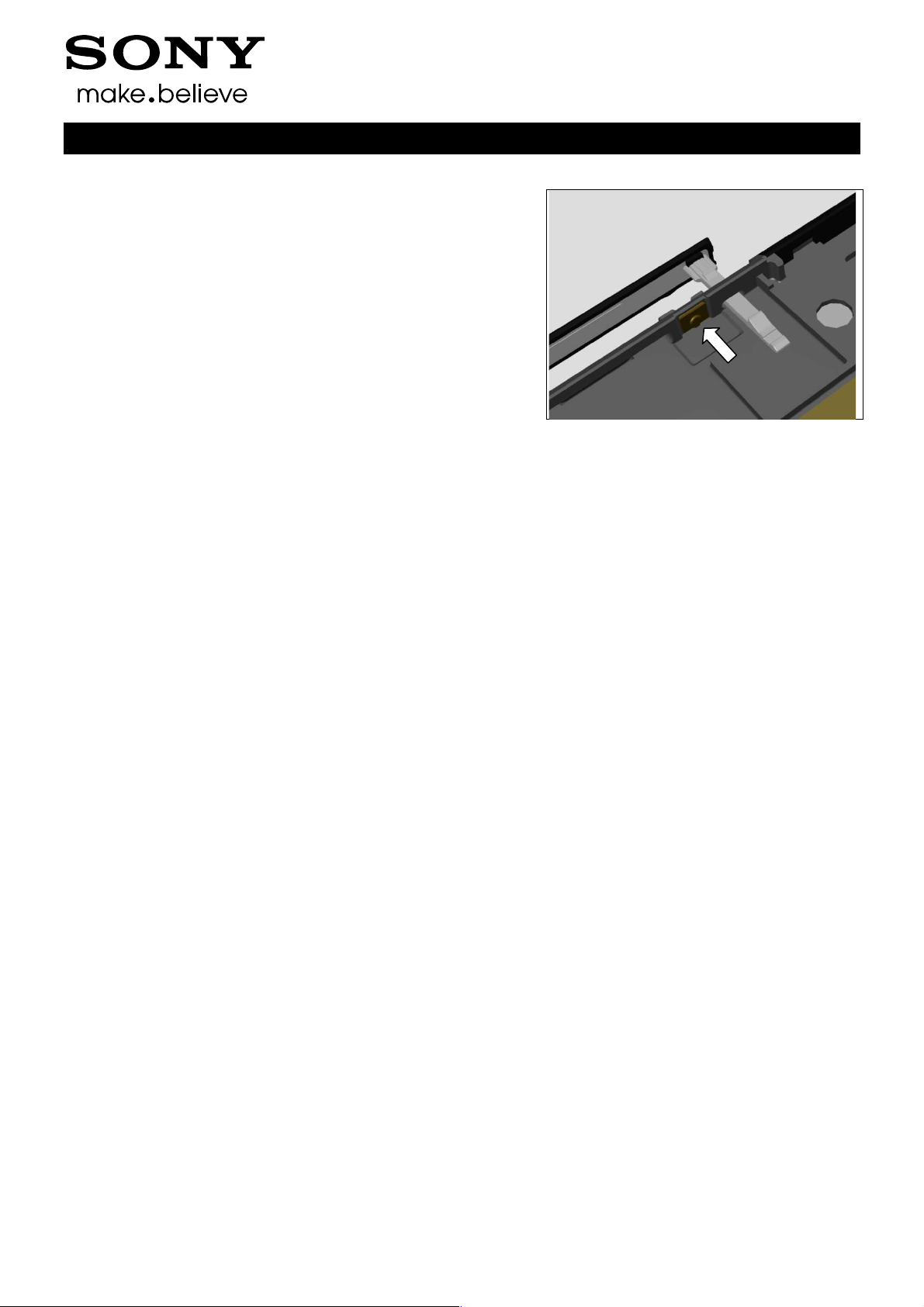
INSTALLATION
Attach the Tape Reset Key onto the Reset Key.
Mount the Reset Key into its hole.
Note direction the Reset Key!
1290-1182 Rev 4
Sony Mobile Communications AB –
52(72)
Company Internal
Working Instructions (mech)
Replacement: Reset Key and Tape Reset Key
Press to secure it attachment.
1290-1182 Rev 4
Sony Mobile Communications AB –
53(72)
Company Internal
Replacement
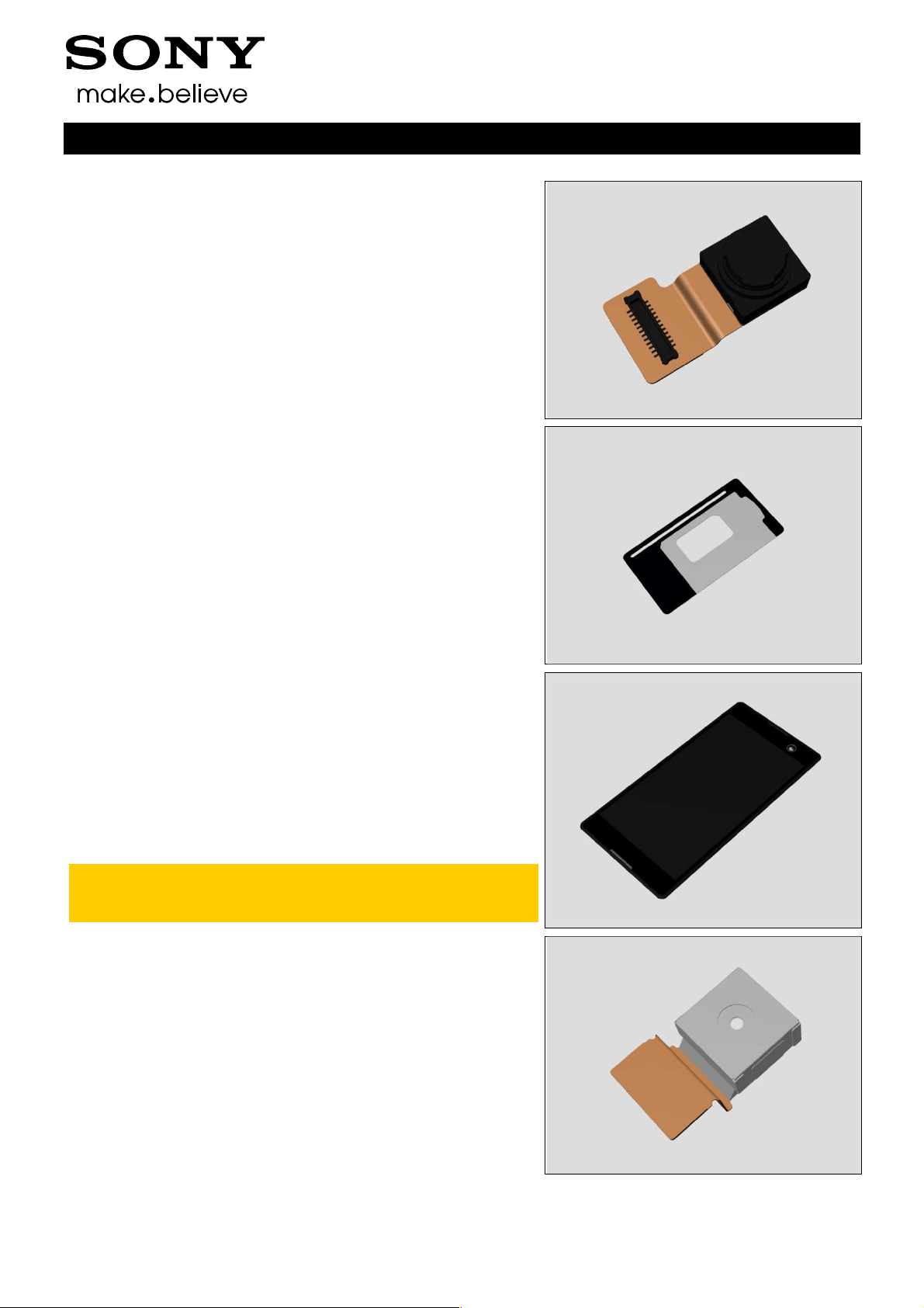
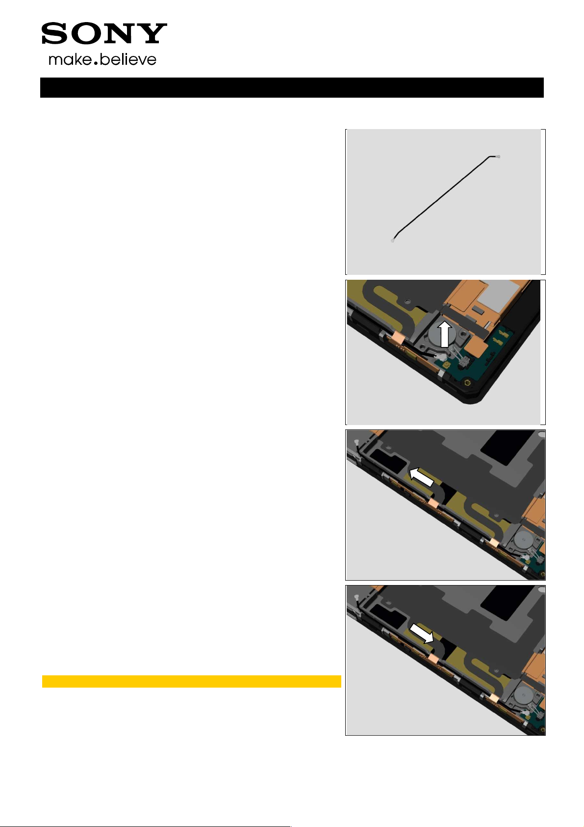
4.38 RF cable
Follow the 3.1 – 3.9 Disassembly instructions!
Follow the 4.26 Removal instructions!
Prepare a new RF cable.
Follow the 4.26 Installation instructions!
Follow the 5.1 – 5.9 Reassembly instructions!
REMOVAL
Disconnect the RF cable connector.
Working Instructions (mech)
Thread the RF cable through the Main FPC to remove it.
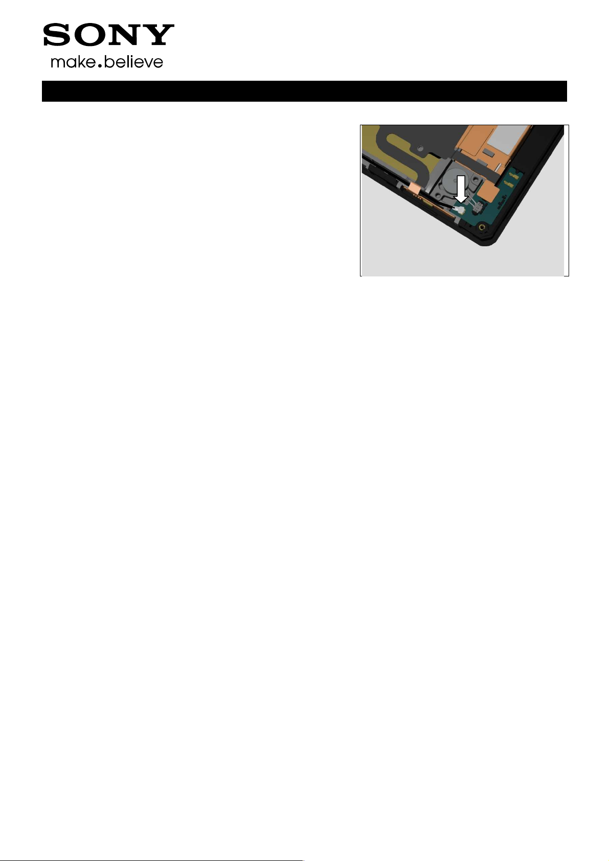
INSTALLATION
Mount the RF cable by threading it through the Main FPC.
Make sure the RF cable is mounted in its cavity.
1290-1182 Rev 4
Sony Mobile Communications AB –
54(72)
Company Internal
Replacement: RF cable
Press to snap RF cable connector.
Working Instructions (mech)
1290-1182 Rev 4
Sony Mobile Communications AB –
55(72)
Company Internal
Replacement
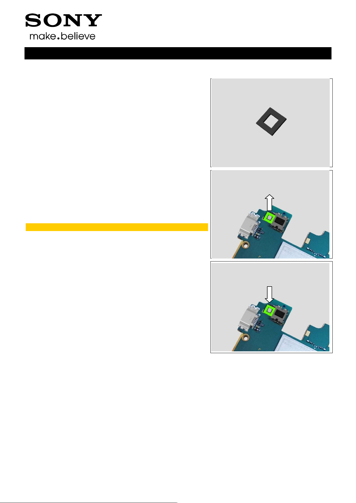
4.39 RGB Gasket
Follow the 3.1 – 3.7 Disassembly instructions!
Prepare a new RGB Gasket.
Follow the 5.3 – 5.9 Reassembly instructions!
REMOVAL
Detach the RGB Gasket.
Scrap! Not to be reused!
Working Instructions (mech)
INSTALLATION
Attach the RGB Gasket.
1290-1182 Rev 4
Sony Mobile Communications AB –
56(72)
Company Internal
Replacement
4.40 SD Cap
Follow the 3.1 – 3.8 Disassembly instructions!
Prepare a new SD Cap.
Follow the 5.2 – 5.9 Reassembly instructions!
REMOVAL
Push the stopper to release the SD Cap by using Flat
Screwdriver.
Working Instructions (mech)
INSTALLATION
Push the stopper to mount the SD Cap by using Flat
Screwdriver.
1290-1182 Rev 4
Sony Mobile Communications AB –
57(72)

Company Internal
Replacement
4.41 SIM Cap
Follow the 3.1 – 3.8 Disassembly instructions!
Prepare a new SIM Cap.
Follow the 5.2 – 5.9 Reassembly instructions!
REMOVAL
Push the stopper to release the SIM Cap by using Flat
Screwdriver.
Working Instructions (mech)
INSTALLATION
Push the stopper to mount the SIM Cap by using Flat
Screwdriver.
1290-1182 Rev 4
Sony Mobile Communications AB –
58(72)

Company Internal
Replacement
4.42 Speaker Mesh
Follow the 3.2 Disassembly instructions!
Prepare a new Speaker Mesh.
Follow the 5.8 Reassembly instructions!
REMOVAL
Detach the Speaker Mesh.
Scrap! Not to be reused!
Working Instructions (mech)
INSTALLATION
Attach the Speaker Mesh.
1290-1182 Rev 4
Sony Mobile Communications AB –
59(72)

Company Internal
Replacement
4.43 Speaker Net
Follow the 3.2 Disassembly instructions!
Prepare a new Speaker Net.
Follow the 5.8 Reassembly instructions!
REMOVAL
Detach the Speaker Net.
Scrap! Not to be reused!
Working Instructions (mech)
INSTALLATION
Attach the Speaker Net in its hole.
Note the direction of the Speaker Net!
Make sure the Speaker Net is mounted into its proper
position.
1290-1182 Rev 4
Sony Mobile Communications AB –
60(72)

Company Internal
Replacement
4.44 Sub PBA
Follow the 3.2 and 3.9 Disassembly instructions!
Prepare a new Sub PBA.
Follow the 5.1 and 5.8 Reassembly instructions!
REMOVAL
Disconnect the Main FPC BtB connector, RF Cable connector
and Vibrator connector.
Detach the Sub PBA.
Working Instructions (mech)
INSTALLATION
Follow the 4.13 Removal and Installation instructions to
replace a new Adhesive Conductive Sub PBA.
Attach the Sub PBA in its proper position and press it.
Press to snap the Main FPC BtB connector, RF Cable
connector and Vibrator connector.
1290-1182 Rev 4
Sony Mobile Communications AB –
61(72)

Company Internal
Replacement
4.45 Vibrator
Follow the 3.2 and 3.9 Disassembly instructions!
Prepare a new Vibrator.
Follow the 5.1 and 5.8 Reassembly instructions!
REMOVAL
Disconnect the Vibrator connector.
Working Instructions (mech)
Detach the Vibrator.
INSTALLATION
Follow the 4.14 Removal and Installation instructions to
replace a new Adhesive Conductive Vibrator.
Attach the Vibrator into its cavity and press it.
1290-1182 Rev 4
Sony Mobile Communications AB –
62(72)

Company Internal
Replacement: Vibrator
Press to snap the Vibrator connector.
Working Instructions (mech)
1290-1182 Rev 4
Sony Mobile Communications AB –
63(72)
Sony Mobile Communications AB
–
Disassembly instructions!
Installation instructions!
5.9 Reassembly instructions!
must
Trouble Shooting Application
Board Swap
Follow the instructions in the Generic Repair Manual
–
Follow the instructions in the Generic Repair Manual
Build swap for customization of the software.
Working Instructions (mech)
Company Internal
Customize of Software
Replacement
4.46 Board Swap
Follow the 3.1 – 3.7
Prepare a new Main PBA.
Follow the 4.33 and 4.39
Follow the 5.3 –
Accelerometer Calibration
replaced units; 1289-2983
– mechanical.
4.47
Replacement
be performed for all
– Change Label
CHANGE LABEL
Build swap for change of label.
4.48 Board Swap
CUSTOMIZE OF SOFTWARE
–
–
1290-1182 Rev 4
–
64(72)
Company Internal
5 Reassembly
The S55t/S55u/D2533/D2502 reassembly is done in the
following order:
1. Display Frame Assy (a) and Ant Speaker Bottom Frame
Assy (b)
2. Core Unit label Tray
3. Main PBA
4. Chat Camera
5. Main Camera
6. 2nd Mic Rubber
7. Ant Top Frame Assy
8. Back Cover Assy
9. SIM Tray
Working Instructions (mech)
1290-1182 Rev 4
Sony Mobile Communications AB –
65(72)
Company Internal
Reassembly
5.1 Display Frame Assy (a)
and Ant Speaker Bottom
Frame Assy (b)
Mount the bottom side of the Ant Speaker Bottom Frame
Assy.
Press to secure its position.
Working Instructions (mech)
Apply 8Ncm±1Ncm torque when tightening the six Screw
M1.4x2.8 with Bits (JCIS No 0).
5.2 Core Unit label Tray
Mount the Core Unit label Tray in its proper position.
Note the direction of the Core Unit label Tray!
Make sure the stopper rib is mounted into the sliding
slot!
1290-1182 Rev 4
Sony Mobile Communications AB –
66(72)
Company Internal
Reassembly
5.3 Main PBA
Mount the Main PBA in its cavity.
Press to snap the Main PBA.
Working Instructions (mech)
Press to snap the RF Cable connector.
Press to snap the Main FPC BtB connector.
1290-1182 Rev 4
Sony Mobile Communications AB –
67(72)
Company Internal
Reassembly
Press to snap the Audio Jack Assy BtB connector.
5.4 Chat Camera
Mount the Chat Camera in its cavity.
Working Instructions (mech)
Press to snap the Chat Camera BtB connector.
5.5 Main Camera
Mount the Main Camera in its cavity.
1290-1182 Rev 4
Sony Mobile Communications AB –
68(72)
Company Internal
Reassembly
Press to snap the Main Camera BtB connector.
5.6 2nd Mic Rubber
Mount the 2nd Mic Rubber and press it.
Working Instructions (mech)
Press to snap the Battery FPC BtB connector.
5.7 Ant Top Frame Assy
Mount the top left side of the Ant Top Frame Assy.
1290-1182 Rev 4
Sony Mobile Communications AB –
69(72)
Company Internal
Reassembly
Press to snap the Ant Top Frame Assy.
Apply 3Ncm±0.5Ncm torque when tightening the Screw
Other Len:1.1 Diam:1.2 with Bits (JCIS No 0).
Working Instructions (mech)
Apply 8Ncm±1Ncm torque when tightening the seven Screw
Torx Len:3.1 Diam:1.4 with Bits (JCIS No 0).
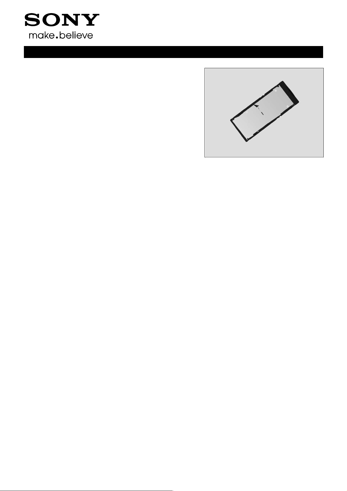
5.8 Back Cover Assy
Follow the 4.19 or 4.20 or 4.21 or 4.22 or 4.23 or 4.24 or
4.25 Removal and Installation instructions to replace a
new certain Back Cover Panel due to it is damaged from
Back Cover Assy disassembly.
Mount the power key side of the Back Cover Assy(1), and
rotate the Back Cover Assy to mount the other side(2).
1290-1182 Rev 4
Sony Mobile Communications AB –
70(72)
Company Internal
Reassembly
Press to snap hooks of the Back Cover Assy.
Make sure all the hooks are snapped!
Check the function of power key, side key and camera
key after assembly.
Close the SD Cap.
Working Instructions (mech)
5.9 SIM Tray
Insert the SIM Tray with fingers.
Close the SIM Cap.
1290-1182 Rev 4
Sony Mobile Communications AB –
71(72)

Company Internal
Rev.
Date
Changes / Comments
Working Instructions (mech)
6 Revision History
1 2014-Jul-18 Initial release
2 2014-Jul-24 Update document since no need Proximity Sensor Calibration any more.
Update the note of Earspeaker removal.
3 2014-Aug-08 Added D2533/D2502
4 2014-Aug-29 Update chapter 4.26, need to scrap battery once disassembly.
1290-1182 Rev 4
Sony Mobile Communications AB –
72(72)
 Loading...