

Sony XL55 Service Manual
XL-55/55C
SERVICE MANUAL
No. S1308XL55////
MICRO COMPONENT SYSTEM
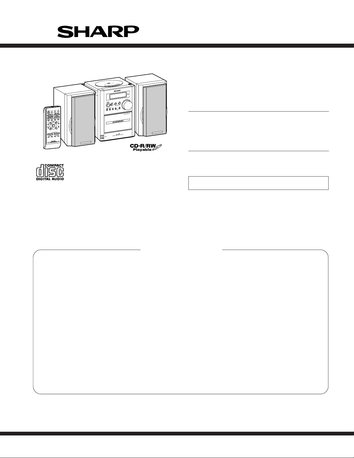
Illustration XL-55
MODEL
XL- 55 Micro Component System consisting of XL- 55 (main unit)
and CP- XL55 (speaker system).
MODEL
XL- 55C Micro Component System consisting of XL- 55C (main
unit) and CP- XL55 (speaker system).
• In the interests of user-safety the set should be restored to its original
condition and only parts identical to those specified should be used.
XL-55
XL-55C
CONTENTS
Page
IMPORTANT SERVICE NOTES (FOR U.S.A. ONLY) ..................................................................................................... 2
SPECIFICATIONS ............................................................................................................................................................ 2
NAMES OF PARTS .......................................................................................................................................................... 3
DISASSEMBLY................................................................................................................................................................. 4
REMOVING AND REINSTALLING THE MAIN PARTS.................................................................................................... 5
ADJUSTMENT.................................................................................................................................................................. 7
TEST MODE ..................................................................................................................................................................... 8
ERROR LIST .................................................................................................................................................................. 12
NOTES ON SCHEMATIC DIAGRAM ............................................................................................................................. 13
TYPES OF TRANSISTOR AND LED.............................................................................................................................. 13
BLOCK DIAGRAM .......................................................................................................................................................... 14
SCHEMATIC DIAGRAM ................................................................................................................................................. 18
WIRING SIDE OF P.W.BOARD...................................................................................................................................... 25
WAVEFORMS OF CD CIRCUIT..................................................................................................................................... 30
TROUBLESHOOTING .................................................................................................................................................... 31
FUNCTION TABLE OF IC .............................................................................................................................................. 37
LCD SEGMENT .............................................................................................................................................................. 44
PARTS GUIDE/EXPLODED VIEW
PACKING OF THE SET (FOR U.S.A. ONLY)
SHARP CORPORATION
– 1 –
This document has been published to be used
for after sales service only.
The contents are subject to change without notice.

XL-55/55C
TO EXPOSED
METAL PARTS
CONNECT TO
KNOWN EARTH
GROUND
TEST PROBE
0.15 µ F
1.5k ohms
10W
VTVM
AC SCALE
FOR A COMPLETE DESCRIPTION OF THE OPERATION OF THIS UNIT, PLEASE REFER
TO THE OPERATION MANUAL.
IMPORTANT SERVICE NOTES (FOR U.S.A. ONLY)
BEFORE RETURNING THE AUDIO PRODUCT
(Fire & Shock Hazard)
Before returning the audio product to the user, perform the following
safety checks.
1. Inspect all lead dress to make certain that leads are not pinched
or that hardware is not lodged between the chassis and other metal
parts in the audio product.
2. Inspect all protective devices such as insulating materials, cabinet,
terminal board, adjustment and compartment covers or shields,
mechanical insulators etc.
3. To be sure that no shock hazard exists, check for leakage current
in the following manner.
* Plug the AC line cord directly into a 120 volt AC outlet.
* Using two clip leads, connect a 1.5k ohm, 10 watt resistor paralleled
by a 0.15µF capacitor in series with all exposed metal cabinet
parts and a known earth ground, such as conduit or electrical
ground connected to earth ground.
* Use a VTVM or VOM with 1000 ohm per volt, or higher, sensitivity
to measure the AC voltage drop across the resistor (See diagram).
* Connect the resistor connection to all exposed metal parts having
a return path to the chassis (antenna, metal cabinet, screw heads,
knobs and control shafts, escutcheon, etc.) and measure the AC
voltage drop across the resistor.
All check must be repeated with the AC line cord plug connection
reversed.
Any reading of 0.3 volt RMS (this corresponds to 0.2 milliamp. AC.)
or more is excessive and indicates a potential shock hazard which
must be corrected before returning the audio product to the owner.
■ General
■ Amplifier (Except for Canada)
■ Amplifier (For Canada)
■ Tuner
Power source
Power
consumption
Dimensions
Weight
Output power
Output terminals
Input terminals
Output power
Output terminals
Input terminals
Frequency range
SPECIFICATIONS
AC 120 V, 60 Hz
48 W
Width: 6-5/16" (160 mm)
Height: 9-1/2" (240 mm)
Depth: 11-11/16" (296 mm)
7.9 lbs. (3.6 kg)
20 watts minimum RMS per channel into 4
ohms from 100 Hz to 20 kHz, 10% total harmonic distortion
Speakers: 4 ohms
Headphones: 16 - 50 ohms (recommended:
32 ohms)
CD digital output (optical)
Subwoofer (Audio signal): 500 mV/47 k
ohms
Video/Auxiliary (audio signal): 500 mV/47 k
ohms
RMS: 40 W (20 W + 20 W) (10 % T.H.D.)
Speakers: 4 ohms
Headphones: 16 - 50 ohms (recommended:
32 ohms)
CD digital output (optical)
Subwoofer (Audio signal): 500 mV/47 k
ohms
Video/Auxiliary (audio signal): 500 mV/47 k
ohms
FM: 87.5 - 108 MHz
AM: 530 - 1,720 kHz
■ CD player
Type
Signal readout
D/A converter
Frequency
response
Dynamic range
Compact disc player
Non-contact, 3-beam semiconductor laser
pickup
1-bit D/A converter
20 - 20,000 Hz
90 dB (1 kHz)
■ Cassette deck
Frequency
response
Signal/noise ratio
Wow and flutter
50 - 14,000 Hz (normal tape)
50 dB (recording/playback)
0.25 % (WRMS)
■ Speaker
Type
Maximum input
power
Rated input power
Impedance
Dimensions
Weight
2-way type speaker system
Tweeter
4" (10 cm) Woofer
40 W
20 W
4 ohms
Width: 6-5/16" (160 mm)
Height: 9-1/2" (240 mm)
Depth: 7-7/8" (200 mm)
4.7 lbs. (2.1 kg)/each
Specifications for this model are subject to change without
prior notice.
– 2 –
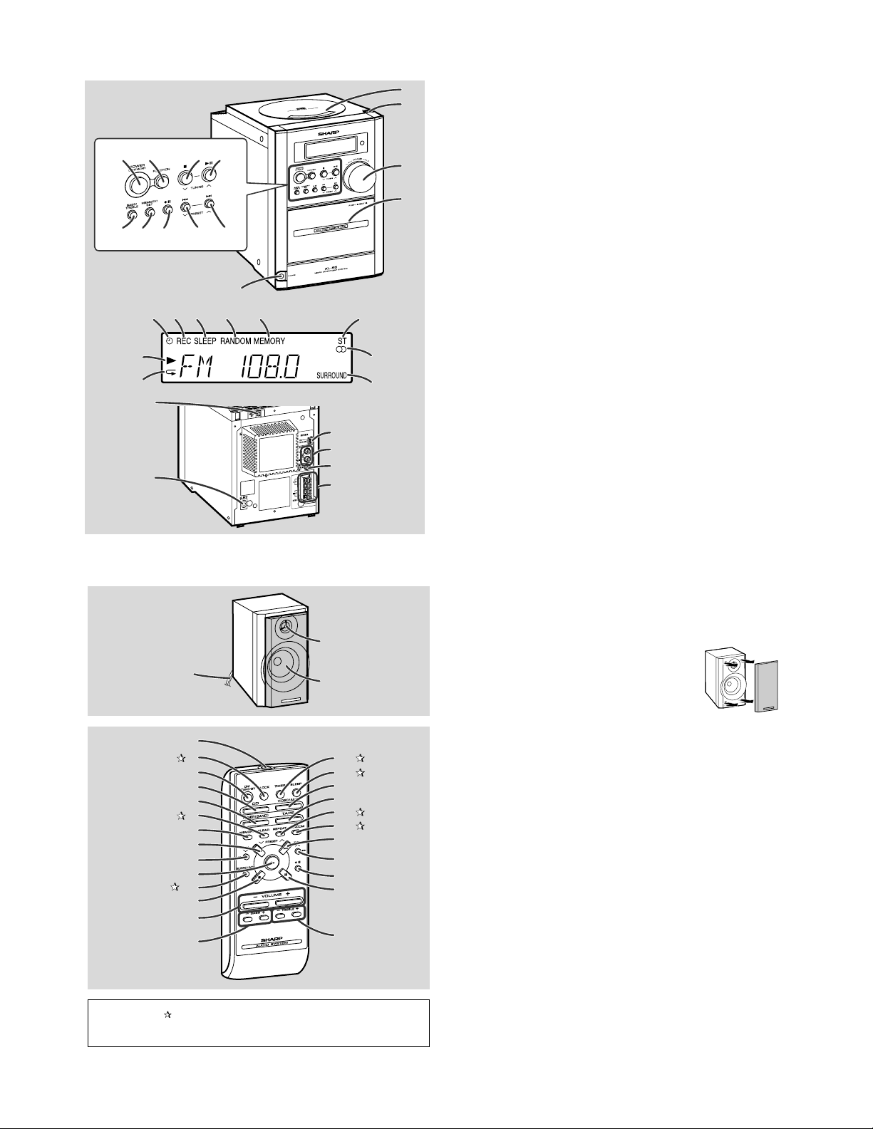
NAMES OF PARTS
XL-55/55C
610789
11 12 13 14
5
15
16
17 18 19
23
24
25
26
27
28
29
30
20
21
22
1
2
3
4
1.CD Compartment
2.CD Eject Button
3.Volume Control
4.Cassette Compartment
5.Headphone Jack
6.Power On/Stand - by Button
7.Function Selector Button
8.CD or Tape Stop, Tuning Down Button
9.CD Play or Pause, Tape Play,
Tuning Up Button
10.Bass/Treble Selector Button
11.Memory/Set Button
12.Tape Record Pause Button
13.CD Track Down or Fast Reverse, Tape Rewind,
Tuner Preset Down Button
14.CD Track Up or Fast Forward, Tape Fast Forward,
Tuner Preset Up Button
15.Timer Play Indicator
16.Tape Record Indicator
17.Sleep Indicator
18.CD Random Play Indicator
19.Memory Indicator
20.FM Stereo Mode Indicator
21.FM Stereo Receiving Indicator
22.Surround Indicator
23.CD Play Indicator
24.CD Repeat Play Indicator
25.CD Digital Output Jack
26.AC Power Input Jack
27.FM/AM Loop Antenna Jack
28.Video/Auxil iary (Audio Signal) Input Jacks
29.Subwoofer Output Jack
30.Speaker Terminals
1
3
2
4
5
6
7
8
9
10
11
12
13
14
15
18
19
20
21
22
23
24
25
26
27
16
17
Buttons with " " mark in the illustration can be operated on the remote control only.
28
1.Tweeter
2.Woofer
3.Speaker Wire
Speaker grilles are removable:
Make sure nothing comes into contact with the
speaker diaphragms when you remove the
speaker grilles.
Remote Control Transmitter
4.
5.Clock Button
Power On/Stand-by Button
6.
CD Button
7.
Tuner and Band Selector Button
8.
9.Clear Button
Memory Button
10.
CD Track Down, Tuner Preset Down Button
11.
CD Fast Reverse, Tuning Down,
12.
Tape Rewind Button
CD or Tape Play Button
13.
14.Surround Button
CD or Tape Stop Button
15.
Volume Up and Down Buttons
16.
Bass Up and Down Buttons
17.
18.Timer Button
19.Sleep Button
Video/Auxiliary Button
20.
Tape Button
21.
22.Repeat Button
23.Random Button
CD Track Up, Tuner Preset Up Button
24.
CD Fast Forward, Tuning Up,
25.
Tape Fast Forward Button
Tape Record Pause Button
26.
CD Pause Button
27.
Treble Up and Down Buttons
28.
– 3 –
XL-55/55C
Shield
Cover
Bracket,
Shield Cover
(G3)x4
ø4x10mm
(G1)x2
ø3x6mm
(G2)x1
(F1)x1
ø3x10mm
(F1)x1
ø3x10mm
(G3)x1
ø3x10mm
(F2)x1
(F2)x1
Power
PWB
Front Panel
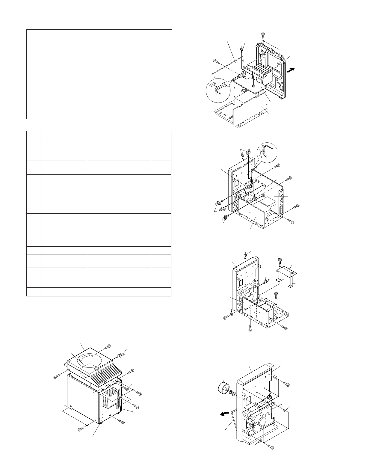
DISASSEMBLY
Caution on Disassembly
Follow the below-mentioned notes when disassembling
the unit and reassembling it, to keep it safe and ensure
excellent performance:
1. Take cassette tape and compact disc out of the unit.
2. Be sure to remove the power supply plug from the wall
outlet before starting to disassemble the unit.
3. Take off nylon bands or wire holders where they need to
be removed when disassembling the unit. After servicing
the unit, be sure to rearrange the leads where they were
before disassembling.
4. Take sufficient care on static electricity of integrated
circuits and other circuits when servicing.
Main PWB
(D1)x1
ø3x10mm
(D3)x1
(D2)x1
(C2)x2
ø3x10mm
Rear Panel
Power Amp. PWB
Power PWB
STEP
1 Top Cabinet 1. Screw .................. (A1) x5 4-1
2 Side Panel
3 Rear Panel 1. Screw .................. (C1) x2 4-1
4 Power Amp. PWB 1. Screw .................. (D1) x1 4-2
5 Main PWB/ 1. Screw .................. (E1) x4 4-3
6 Front Panel 1. Screw .................. (F1) x2 4-4
7 Power PWB 1. Screw .................. (G1) x2 4-4
8 Tape Mechanism 1. Screw .................. (H1) x4 4-5
9 Display PWB 1. Knob .................... (J1) x1 4-5
10 CD PWB(Note)/ 1. Screw .................. (K1) x4 5-1
11 CD Mechanism 1. Screw .................. (L1) x3 5-2
Note:
After removing the connector for the optical pickup from the
connector, wrap the conductive aluminium foil around the front end
of the connector so as to protect the optical pickup from electrostatic damage.
REMOVAL PROCEDURE FIGURE
2. Socket ................. (A2) x2 4-1,3
(Left/Right)
Headphones PWB 2. Socket ................. (E2) x4
Open Close Switch PWB
Jack PWB 3. Socket ................. (K3) x3
1. Screw .................. (B1) x4 4-1
2. Screw .................. (C2) x2 4-2
2. Socket ................. (D2) x1
3. Socket ................. (D3) x1
3. Socket ................. (E3) x1
2. Socket ................. (F2) x2
2. Shield Cover ....... (G2) x1
3. Screw .................. (G3) x5
2. Screw .................. (J2) x8
2. Screw .................. (K2) x2
Tape
Mechanism
PWB
(E2)x2
(A2)x1
(E2)x2
Power PWB
Figure 4-2
(E3)x1
(E1)x1
ø3x10mm
Headphones
PWB
(E1)x1
ø3x10mm
Main PWB
(E1)x1
ø3x10mm
(E1)x1
ø3x10mm
Figure 4-3
(A1)x1
ø3x10mm
Side Panel
(Right)
CD PWB
(B1)x2
ø3x10mm
Top Cabinet
Rear Panel
(A1)x1
ø3x10mm
Figure 4-1
(A2)x1
(B1)x2
ø3x10mm
(C1)x1
ø3x10mm
(A1)x1
ø3x10mm
(A1)x2
ø3x10mm
(C1)x1
ø3x10mm
Side Panel
(Lift)
– 4 –
(J1)x1
Open
Cassette
Holder
Figure 4-4
Front Panel
Figure 4-5
Display PWB
(J2)x8
ø2.6x10mm
Tape
Mechanism
(H1)x4
ø2.6x10mm
<A>
Pinch Roller
(B1)x1
Pinch Roller
Pawl
Main Belt
(C1)x1
FF/REW Belt
(C2)x1
REW/FF
Clutch
Motor
(K2)x1
(L1)x3
ø2.6x10mm
Top Cabinet
CD Mechanism
ø2.6x10mm
Top Cabinet
CD PWB
(K1)x4
ø2.4x10mm
(K2)x1
ø2.6x10mm
Open/Close
Switch PWB
(K3)x1
XL-55/55C
(K3)x2
Jack
PWB
CD Mechanism
Figure 5-1
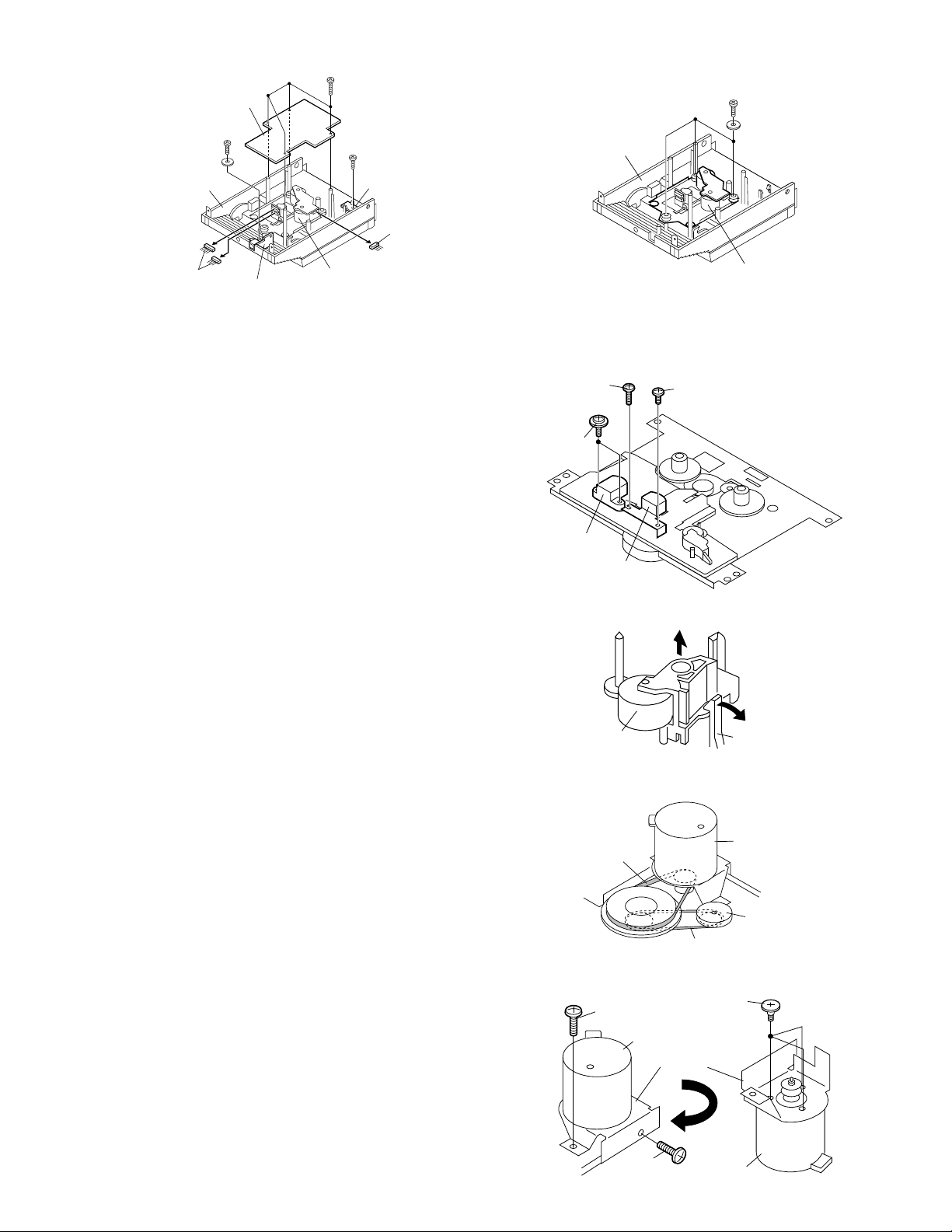
REMOVING AND REINSTALLING THE MAIN PARTS
TAPE MECHANISM SECTION
Perform steps 1 to 6 and 8 of the disassembly method to
remove the tape mechanism. (See page 4.)
How to remove the record / playback and erase
heads (See Fig. 5-3.)
1. Remove the screws (A1) x 2 pcs., to remove the erase
head.
2. Remove the screws (A2) x 2 pcs., to remove the record/
playback head.
Note:
After replacing the heads and performing the azimuth
adjustment, be sure to apply screwlock.
How to remove the pinch roller (See Fig. 5-4.)
1. Carefully bend the pinch roller pawl in the direction of the
<A>, and remove the pinch roller (B1) x 1 pc.,
arrow
upwards.
(A2)x1
ø2x7mm
(A1)x2
ø2x8mm
Erase Head
Record/
Playback Head
Figure 5-2
(A2)x1
ø2x3mm
Figure 5-3
How to remove the belts (See Fig. 5-5.)
1. Remove the main belt (C1) x 1 pc., from the motor pulley.
2. Remove the FF/REW belt (C2) x 1 pc., from the REW/FF
roller.
3. Put on the belts in the reverse order of removal.
Note:
When putting on the belt, ascertain that the belt is not twisted,
and clean it.
How to remove the motor
(See Fig. 5-6.)
1. Remove the main belt.
2. Remove the screws (D1) x 2 pcs., to remove the motor
bracket.
3. Remove the screws (D2) x 3 pcs., to remove the motor.
Note:
When mounting the motor, pay attention to the motor mounting
angle.
– 5 –
(D1)x1
ø2x4mm
Motor
(D1)x1
ø2x4mm
Figure 5-4
Figure 5-5
(D2)x3
Special
Screw
Motor
Bracket
Motor
Figure 5-6

XL-55/55C
Pickup Unit
(A2) x2
ø2.6 x6mm
(A1) x2
CD Mechanism
Shaft
(A3) x1
Gear
(A5) x1
StopWasher
(A4) x1
Mechanism Cover
(A1) x2
Stop
Washer
Driver
(E1)x1
Stop Washer
Mechanism
Chassis
Washerx2
Flywheel
How to remove the flywheel (See Fig. 6-1.)
1. Remove the belt.
2. Remove the stop washer (E1) x 1 pc., with a small precision
screwdriver to extract the flywheel from the capstan metal.
Note:
When the stop washer is deformed or damaged, replace it
with a new one.
How to reinstall the parts
Install each part in the reverse order of the removal with care.
Figure 6-1
How to remove the tape mechanism PWB
(See Fig. 6-2.)
1. Remove the screw (F1) x 1 pc., to remove the tape
mechanism PWB.
2. Remove the screw (F2) x 1 pc.
3. Remove the solder joints (F3) x 2 pcs., to remove the tape
mechanism PWB.
CD MECHANISM SECTION
Perform steps 1, 10 and 11 of the disassembly method to
remove the CD mechanism. (See page 4.)
How to remove the pickup (See Fig. 6-3)
1. Remove the mechanism cover, paying attention to the
pawls (A1) x 4 pcs.
2. Remove the screws (A2) x 2 pcs., to remove the shaft (A3)
x 1 pc.
3. Remove the stop washer (A4) x 1 pc., to remove the gear
(A5) x 1 pc.
4. Remove the pickup.
(F1)x1
ø2x3mm
Tape
Mechanism
PWB
(F2)x1
ø2x8mm
Tape
Mechanism
PWB
(F3)x2
Solder
Joint
Figure 6-2
Note:
After removing the connector for the optical pickup from the
connector, wrap the conductive aluminium foil around the
front end of connector remove to protect the optical pickup
from electrostatic damage.
Figure 6-3
– 6 –
MECHANISM SECTION
• Driving Force Check
Torque Meter
Play: TW-2412 Over 80 g
• Torque Check
Torque Meter
Play: TW-2111 30 to 60 g. cm
Fast forward: TW-2231 55 to 140 g.cm
Rewind: TW-2231 55 to 140 g.cm
• Tape Speed
Test Tape
MTT-111 Variable 3,000 ± Headphone
Adjusting
Point
resistor in 90 Hz terminal
motor.(M901)
TAPE MECHANISM
Specified Value
Specified Value
Specified
Value
Instrument
Connection
ADJUSTMENT
• FM Mute Level
Signal generator: 1 kHz, 40 kHz dev., FM modulated
Frequency
98.00 MHz 98.00 MHz VR351*1 Input: CNP301
(30 dBµV) Output: Speaker
*1. Adjust so that an output signal appears.
• FM Detection
Signal generator: 10.7 MHz, FM sweep generator
Test
Stage
FM IF 10.7 MHz 98.00 MHz T304(Turn Input: Pin 1 of
Display
Frequency Frequency
Display
Adjusting
Parts
Terminal
Setting/
Adjusting
Parts
the core of IC301
T304 fully
counterclockwise).
XL-55/55C
Instrument
Connection
Instrument
Connection
M901
Tape
Motor
Variable
resistor
in motor
Figure 7-1 ADJUSTMENT POINT
TUNER SECTION
fL: Low-renge frequency
fH: High-renge frequency
• AM IF/RF
Signal generator: 400 Hz, 30%, AM modulated
Test Stage
Frequency Frequency
Display
IF 450 kHz 1,602 kHz T351 *1
AM Band — 531 kHz (fL): T306 *2
Coverage 1.1 ± 0.1 V
AM 990 kHz 990 kHz T302 *1
Tracking
*1. Input: Antenna Output: Speaker terminal
*2. Input: Input is not connected Output: TP301
• Check FM VT
Signal generator: 1 kHz, 40 kHz dev., FM modulated
Frequency
87.5 MHz 87.5 MHz 3.4 V ± 1.0 V TP301
108 MHz 108 MHz 7.8 V ± 1.0 V TP301
Display
Check Point
Setting/
Adjusting
Parts
Instrument
Connection
Instrument
Connection
• FM RF
Signal generator: 1 kHz, 75 kHz dev., FM modulated
Test Stage
FM Band — 87.50 MHz (fL): L303 *1
Coverage 3.4 ± 0.1 V
FM RF 98.00 MHz 98.00 MHz L302 *2
Frequency Frequency
Display
(10~30 dB)
Setting/
Adjusting
Parts
Instrument
Connection
*1. Input: Antenna, Output: TP301
*2. Input: Antenna, Output: Speaker Terminal
MAIN PWB
IC302
TP301
R336
T306
FM Band
Coverage fL
FM IF
L302
FM OSC.
L303
T304
FM RF
T302
9
IC301
1
AM
Tracking
BF301
IC303
AM IF
T351
CF352
AM Band
Coverage fL
AM OSC.
FM Mute
Level
VR351
Figure 7-2 ADJUSTMENT POINTS
CNP301
ANTENNA
SOCKET
– 7 –
XL-55/55C
• Setting the Test Mode
Keeping the REW/REV button and BASS/TREBLE button
pressed, turn on POWER. Then, the frequency is initially set
in the memory as shown in Table. Call it with the PRESET
button to use it for adjustment and check of tuner circuit.
Preset No. FM STEREO
1 87.50 MHz
2 108.00 MHz
3 98.00 MHz
4 90.00 MHz
5 106.00 MHz
11~25 ––––
Preset No.
6 531 kHz
7 1,602 kHz
8 990 kHz
9 603 kHz
10 1,404 kHz
AM
Preset No.
26 106.00 MHz
27 90.00 MHz
28 98.00 MHz
29 108.00 MHz
30 87.50 MHz
FM MONO
TEST MODE
The test mode applied to this microcomputer has three modes, namely ordinary test mode to be used for adjustment or
measurement, aging test mode to be used for aging test, and self-diagnosis test mode for self-inspection in case of final product
inspection.
1. Turning on the test mode
To turn on the specific test mode, press the POWER ON/STAND-BY button, holding down the following two buttons in the
ordinary stand-by mode (power off state). In this case only the main unit button is valid. Even when the POWER of remote control
button is set to on, the test mode is not turned on.
[Ordinary test mode]
1. CD Test Mode (TEST 1)…………………… BASS/TREBLE + FF/FWD
2. Tuner Test Mode (TEST 2)………………… BASS/TREBLE + REW/REV
3. Electronic volume Test Mode (TEST 3)……BASS/TREBLE + REC
4. Timer Test Mode (TEST 4)………………… MEMORY/SET + REC
5. LCD Test Mode (TEST 5)……………………MEMORY/SET + REW/REV
[Self-diagnosis Test Mode]
1. Button input diagnosis test mode (TEST6).…
2. CD Test Mode (TEST 1)
In the CD test mode the operation of each step is enabled even when the LID-SW is off. However, if focus cannot be set in step 3 or any
error processing is started, it is impossible to proceed to the next step. When the error processing is started, operations other than
termination of test mode by pressing the POWER ON/STAND-BY button or return to the step 1 by pressing the STOP button are inhibited.
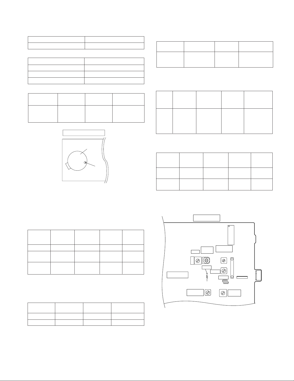
1. Step 1 Mode
When the CD test mode is turned on, the following indication lights, the processing (until turning-off of CD STB terminal of CD
initialization operation flow) is executed, and the next button input is waited.
MEMORY/SET + PLAY
After lighting for one second
If the following operation buttons are pressed in this state, the operation is performed as follows.
"
POWER ON/STAND-BY
"...The test mode is turned off, the power is turned off, and the ordinary stand-by mode is set.
"FF/FWD".................After the pickup returns once to the innermost periphery, it slides toward the outer periphery while this
button is held down.
"REW/REV"..............After the pickup returns once to the innermost periphery, it slides toward the inner periphery while this
button is pressed. However, if PU-IN is on, input is invalid.
"PLAY" .....................Shift to step 2
"STOP".....................Invalid
"REC PAUSE"..........Shift to step 5
– 8 –
XL-55/55C
* In case of initialization the pickup is moved toward the inner periphery. Any buttons other than POWER ON/STAND-BY button
are not accepted until the shift of pickup to the inner periphery is completed at this time. If PU-IN SW ON cannot be detected
within 10 seconds, the slide motor is stopped, and the following error indication appears. Press the POWER ON/STAND-BY
button to end the test mode, or press the STOP button to return to step 1. Any other operations are inhibited.
2. Step 2 Mode
When the "PLAY" button is pressed in this mode, the laser lighting command LDON (8400) is sent, and the laser is turned on.
Other operations are not performed.
If the following buttons are pressed in this state, the operation is performed as follows.
"
POWER ON/STAND-BY
"FF/FWD" ................The pickup slides toward the outer periphery while this button is held down.
"REW/REV" .............The pickup slides toward the inner periphery while this button is held down. However, if PU-IN is on, input
"PLAY".....................Shift to step 3
"STOP" ....................Return to step 1
"REC PAUSE" .........Shift to step 5
" ..The test mode is turned off, the power is turned off, and the ordinary stand-by mode is set.
is invalid.
3. Step 3 Mode
The laser is kept lighting. The processing (until turning-on of CLV servo of CD initialization operation flow) is executed, and
the next button input is waited. (The focus servo is turned on, and focus search is performed.)
The focus search is repeated until the focus is set.
When the following operation buttons are pressed in this state, the operation is executed as follows.
POWER ON/STAND-BY
"
"FF/FWD" ................The pickup slides toward the outer periphery while this button is held down.
"REW/REV" .............The pickup slides toward the inner periphery while this button is held down. However, if PU-IN is on, input
"PLAY".....................If the focus has been set, shift to step 4 is executed. If the focus has not been set, acceptance is inhibited.
"STOP" ....................Return to step 1
"REC PAUSE" .........Shift to step 5
*If the focus is disturbed after it has been set, the process returns to step 1.
4. Step 4 Mode (Only focus "OK" can make this item showing)
The CLV servo ON command (8600) sending operation is performed, and the next button input is waited. (The disc is rotated
to perform CLV locking.)
" ..The test mode is turned off, the power is turned off, and the ordinary standby mode is set.
is invalid.
The time display indicates always "0:00".
When the following buttons are pressed in this state, the operation is executed as follows.
"
POWER ON/STAND-BY
"FF/FWD" ................The pickup slides toward the outer periphery while this button is held down.
"REW/REV" .............The pickup slides toward the inner periphery while this button is held down. However, if PU-IN is on, input
"PLAY".....................Shift to step 5
"STOP" ....................Return to step 1
"REC PAUSE" .........Shift to step 5
*If the focus is disturbed, the process returns to step 1.
" ..The test mode is turned off, the power is turned off, and the ordinary standby mode is set.
is invalid.
– 9 –

XL-55/55C
5. Step 5 Mode
The CD initialization operation flow is executed to the end, the mute is set to off, and playback is started. Even when the
playback reaches the outermost periphery of disc, the operation does not stop. The LCD display indicates the playback past
time as in case of ordinary CD playback.
When the following operation buttons are pressed in this sate, the operation is executed as follows.
POWER ON/STAND-BY
"
"FF/FWD".................The pickup slides toward the outer periphery while this button is held down.
"REW/REV"..............The pickup slides toward the inner periphery while this button is held down. However, if PU-IN is on, input
"PLAY" .....................Invalid
"STOP".....................Return to step 1
*If the focus is disturbed, the process returns to step 1.
Other cautions
• TOC IL is not executed in the test mode.
• As for button operations other than those shown above, only the sound volume operation (with JOG) is accepted.
3. Tuner Test Mode (TEST 2)
1. Outline of tuner (radio) test mode
The tuner test mode is intended to store the adjustment and measurement frequencies in the preset memory CH without
frequency setting by adjusting personnel when the tuner section is adjusted in the production line.
2. Details of tuner test mode
When the power is turned on by using the POWER ON/STAND-BY button while the BASS/TREBLE and REW/REV buttons
are held down in POWER OFF state, the frequency for adjustment and measurement of destination specified by the AREA
terminal is preset and stored in the preset memory CH. However, Ordinary 1 and Ordinary 2 are set to the designation
(destination selected by SPAN switching operation) set when the test mode is obtained.(Memory/Set+Function Key Span
Charged) (As for frequencies to be preset and stored for each destination, refer to item 3.)
The tuner test mode is started from preset No.1.
The operations of test mode are identical with the ordinary operations of TUNER function. However, FUNCTION switching
is invalid.
"...The test mode is turned off, the power is turned off, and the ordinary standby mode is set.
is invalid.
Since it is necessary to discard the content of preset memory when the tuner test mode is ended, "0000" or "1111" bits are
written in the memory to be checked in case of memory check (in case of initial setting) so that memory abnormality is detected
in case of initial setting so as to ensure memory initialization.
When the tuner test mode is turned on, the following indication lights for one second.
The TUNER TEST2 mode is set as a result of BASS/TREBLE+ REW/REV.
•
When POWER is set to OFF, the memory of TEST2 mode is protected.
When the power is turned on again, the ordinary operation is enabled while the data is stored in the
memory (besides TUNER).
If AC OFF state is maintained in this state for about 1/2 day, start is executed in the initial state.
• To clear the whole memory, insert the AC cord, holding down MEMORY + STOP.
->
POWER OFF
->
IF AC is set to OFF in the TEST2
mode, the initial state is restored.
– 10 –
3. Preset frequencies for various destinations (random preset memory)
XL-55/55C
CH
1 FM 87.50 MHz
2 FM108.00 MHz
3 FM FM 98.00 MHz
4 STEREO FM 90.00 MHz
5 FM106.00 MHz
• The hatched sections of the table are not stored in memory.
4. Electronic volume Test Mode (TEST 3)
When the test mode is set, the following indication lights for one second.
When this mode is set, BASS/TREBLE is set to 0 (0 dB) and start-up function is set to CD when volume is -14 dB (STEP 23).
The button operations in the test mode are the same as those of ordinary operation excepting sound volume UP/DOWN.
(1) The indication is the same as that of ordinary operation excepting test mode setting.
(2) The sound volume control with the sound volume UP/DOWN button is only the following 3 steps unlike the ordinary state.
Volume(3) BASS/TREBLE is switched when button operation is performed.
BAND
∞ (STEP 0) <-> Volume-14 dB (STEP 23) <-> Volume-0 (STEP 30)
Europe 2, 4
BAND
6 AM 531 kHz
7 AM1602 kHz
8 AM AM 990 kHz
9 AM 603 kHz
10 AM1404 kHz
11-15 LW
Europe 2, 4CH
CH
16-25
26 FM106.00 MHz
27 FM 90.00 MHz
28 FM FM 98.00 MHz
29 MONO FM108.00 MHz
30 FM 87.50 MHz
BAND
Europe 2, 4
5. Timer test Mode (TEST 4)
When the test mode is set, the following indication lights for one second.
The current time and timer time are set in the following procedure to perform the timer playback.
1.Set the current time to 1:00, set the timer to ON time 1:05, set the function to Aux, and set volume STEP 12. One minute is counted
as one second, and the timer playback operation is performed. The fade-in (when playback is started) is executed at a rate of
one step for 1 sec. After completion of fade-in the fade-out is executed at a rate of one step for 1 sec (WAIT 1 sec inserted). After
completion of fade-out the power is turned off (after WAIT 1 sec), and the mode is changed to the standby mode.
The indication during operation is the same as that of ordinary timer operation.
6. LCD Test Mode (TEST 5)
When the LCD test mode is set, all the LCD segments are lighted. After that the indication is changed as follows according to
the "PLAY" button input.
Lighting of all segments Lighting of odd segments Lighting of even segments
– 11 –
XL-55/55C
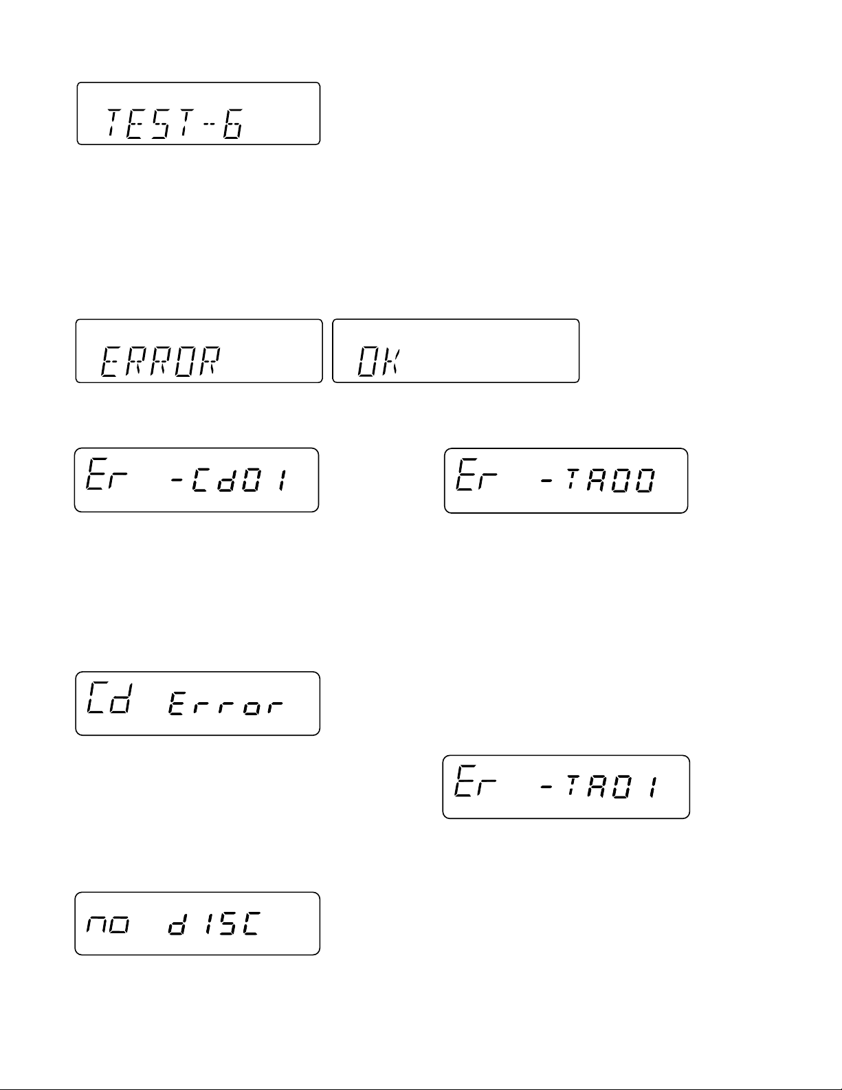
7. Key input diagnosis Test Mode (TEST 6)
When the test mode is set, the following indication appears.
This test mode is intended to check whether all the main unit buttons can be detected. Accordingly, in this test mode checking as to
whether the "POWER ON/STAND-BY" button was pressed after all the buttons shown below were pressed is performed. If the result
is OK, OK is indicated. Even any one of keys was not pressed, an error is indicated. In case of OK termination or error termination
exit from this mode occurs when the "POWER ON/STAND-BY" button is pressed next time, and the standby mode is set.
1. In case of "MEMORY/SET" + "PLAY"+ "POWER ON/STAND-BY"
Since SURROUND and RDS are not provided, the following 9 buttons are detected as all buttons.
PLAY, POWER ON/STAND-BY, BAND, BASS/TREBLE, FUNCTION, MEMORY/SET, REC PAUSE, REW, FF, STOP.
The OK/NG indication of test result is as follows.
ERROR LIST
PU-IN SW detection error
Tape mechanism error 1
Error content............The detection SW cannot detect ON
after a fixed period of time even if the
microcomputer controls the CD pickup
to return to the innermost position.
Probable cause........Defective or poorly connected PU-IN
SW or slide motor.
Action .......................Solve the problem and turn on the power
again.
CD read error
Error content ........... Disc data cannot be read properly or
even if it can be read, the disc is not a
playable one.
Probable cause....... The disc is loaded upside down, not CD-
DA, scratches, stains, etc.
Action ...................... Open the CD lid, then reload the disc
correctly. Remove the scratches or stains
on the disc.
NO DISC
Error content ........... Focusing is impossible.
Probable cause....... The disc is loaded upside down, not CD-
DA, scratches, stains, etc.
Action ...................... Open the CD lid, then reload the disc
correctly. Remove the scratches or stains
on the disc.
Error content........... The detection SW "CAM-SW" cannot
detect ON (mechanism in operation) even
if the motor and solenoid are controlled
to play back, fast forward, rewind, or
record the tape.
Probable cause....... Mechanism is in operation when this
message appears: Defective or poorly
connected CAM-SW. Mechanism stops:
Defective or poorly connected motor or
solenoid.
Action ...................... Solve the problem and turn on the power
again.
Tape mechanism error 2
Error content ........... Initialization cannot be completed when
the microcomputer controls the motor
and solenoid to initialize the tape
mechanism (to set the mechanism to the
stop mode). The detection SW "CAMSW" cannot detect OFF While the
mechanism is in operation.
Probable cause....... Mechanism is in operation when this
message appears: Defective or poorly
connected CAM-SW. Mechanism stops:
Defective or poorly connected motor or
solenoid.
Action ...................... Solve the problem and turn on the power
again.
– 12 –

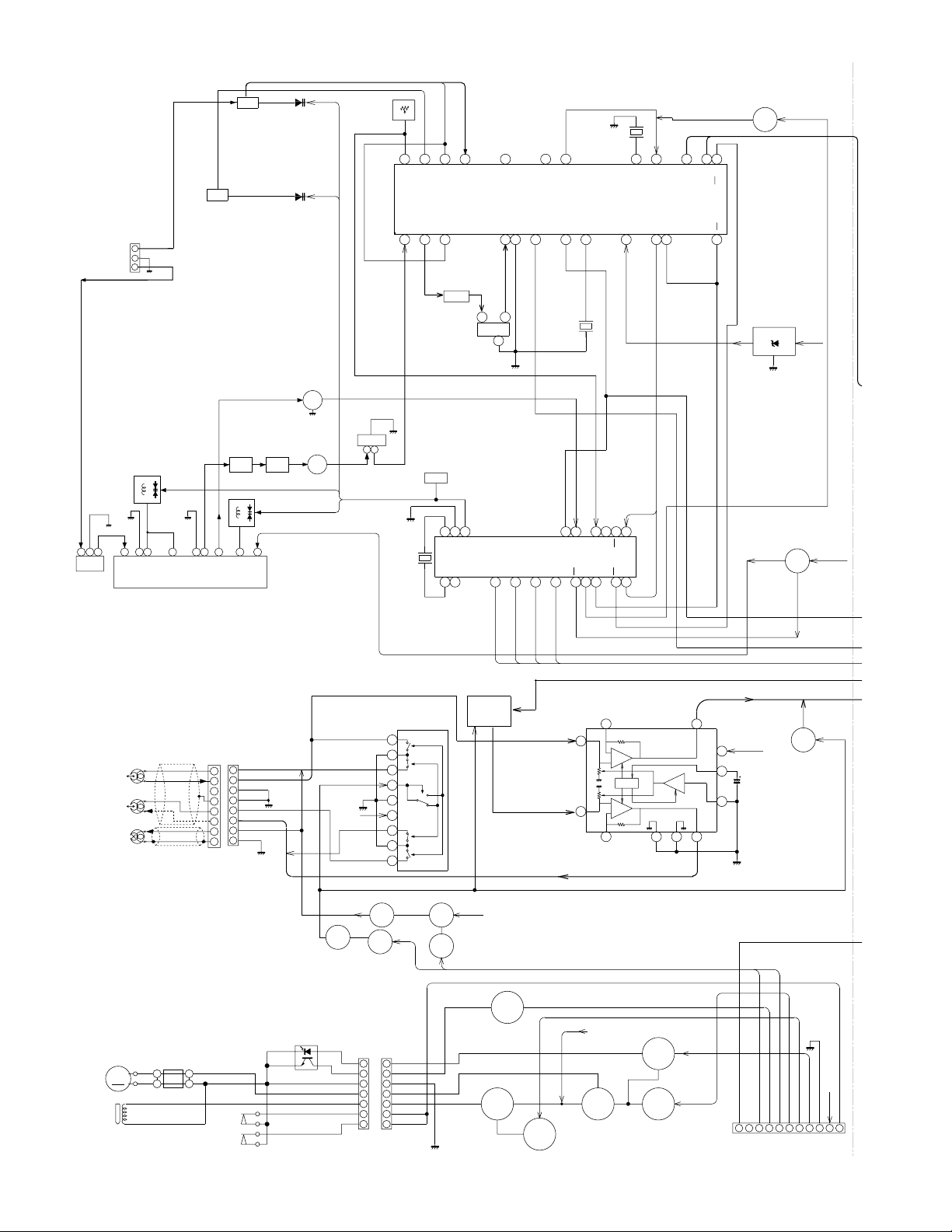
NOTES ON SCHEMA TIC DIAGRAM
XL-55/55C
• Resistor:
To differentiate the units of resistors, such symbol as K and
M are used: the symbol K means 1000 ohm and the symbol
M means 1000 kohm and the resistor without any symbol is
ohm-type resistor. Besides, the one with “Fusible” is a fuse
type.
• Capacitor:
To indicate the unit of capacitor, a symbol P is used: this
symbol P means micro-micro-farad and the unit of the
capacitor without such a symbol is microfarad. As to
electrolytic capacitor, the expression “capacitance/withstand
voltage” is used.
(CH), (TH), (RH), (UJ): Temperature compensation
(ML): Mylar type
(P.P.): Polypropylene type
• Schematic diagram and Wiring Side of P.W.Board for this
model are subject to change for improvement without prior
notice.
REF. NO
SW700 VOLUME ON—OFF
SW701 POWER ON/STAND-BY ON—OFF
SW702 FUNCTION ON—OFF
SW703 STOP/CLEAR,TUNING DOWN ON—OFF
SW704 PLAY/CD PAUSE,TUNING UP ON—OFF
SW705 BASS/TREBLE ON—OFF
SW706 MEMORY/SET ON—OFF
DESCRIPTION
POSITION POSITIONREF. NO
• The indicated voltage in each section is the one measured
by Digital Multimeter between such a section and the chassis with no signal given.
1. In the tuner section,
( ) indicates AM
< > indicates FM stereo
2. In the main section, a tape is being played back.
3. In the deck section, a tape is being played back.
( ) indicates the record state.
4. In the power section, a tape is being played back.
5. In the CD section, the CD is stopped.
• Parts marked with “ ” ( ) are important for
maintaining the safety of the set. Be sure to replace these
parts with specified ones for maintaining the safety and
performance of the set.
DESCRIPTION
SW707 REC/PAUSE ON—OFF
SW708 REW/PRESET DOWN ON—OFF
SW709 FF/PRESET UP ON—OFF
SW800 PICKUP IN ON—OFF
SW801 CD LID OPEN/CLOSE ON—OFF
SW901 FOOL PROOF ON—OFF
SW902 CAM ON—OFF
FRONT
VIEW
ECB
(S)(G)(D)
(1) (2) (3)
TYPES OF TRANSISTOR AND LED
2HA1015 GR
2HC1815 GR
2SC2001 K
2SK2541
HSB562 C
KRA102 M
KRA107 M
KRC102 M
KRC104 M
KRC107 M
SC1674 C
FRONT
VIEW
BCE
KTC2026 Y
Figure 13 TYPES OF TRANSISTOR AND LED
MPG3372X
FRONT
VIEW
1 2 3
SVC348S
KDV147B
– 13 –
XL-55/55C
BF301
BAND
PASS
FILTER
AM/FM
ANTENNA
TERMINALS
CNP301
1
2
3
FM RF
L302
VD303
FM FRONT END
TA7358AP
VT
IC301
T306
AM OSC.
78654323211
AM TRACKING
T302
FM IF FM IF
CF303 T304
FM OSC
VT
L303
VD302
9
VD301-1
SVC348S
VD301-2
SVC348S
Q302
FM IF AMP.
Q306
FM MUTE LEVEL
VR351
10K(B)
AM OSC OUT
24 22
AM OSC OUT
FM IF IN
10.7MHz
CF302
3
1
FM IF
VT
D_GND
X352
4.5MHz
21
23
FM AFC
AM RF IN
AM OSC IN AM MIX OUT
FM IF DET./FM MPX./AM IF
LA1832S
REG
AM IF
T351
AM MIX OUT
TP301
21
22
20
VSS
AOUT
X OUT
LC72131
X IN
NC
1 2 3 4
20
IC303
4 3 2 1
AM IF IN
3
1
CF352
2
IC302
PLL (TUNER)
CE
VSM
AM IF IN
GND
5
DI
19
AM LOW CUT
SD
6
CL
6
5
18
FM/AM OUT
STEREO
7
CF351
FM IF
17
16
VDD
FM IN
FM
DO
7
X351
456kHz
FM DET
8
14
15
AM IN
FM
MUTE
8
9
9
+5V
12
13
NC
SW
IF IN
MO/ST
IF REQ
10
11
16
17
MPX VCO
VCC
10
MPX IN
PHASE
IF OUT
11
14
15
R-CH OUT
13
MO/ST
L-CH OUT
PHASE
(AM/FM)
12
SWITCHING
+5V
Q351
FM+B
ZD351
A_GND
R_MUTE
A_12V
R-MUTE
Q360
A_12V
RECORD/
PLAYBACK
HEAD
L-CH
R-CH
ERASE
HEAD
M901
TAPE MOTOR
M
SOL901
SOLENOID
CE
DI
CL
DO
IC101
HEAD SELECTOR
BA3126N
BIAS OSC
Q151
L151
Q172
SWITCHING
7
7
6
6
5
5
4
4
3
3
2
2
1
1
CNS901
1
2
3
4
5
6
7
8
9
P.F
CAM SW
REC SW
P/B SW
CONT
IC101
P/B SW
REC SW
REC
L-CH
CNP101
CNS101
L-CH
8
8
L-CH
7
7
A-GND
6
6
A-GND
5
5
R-CH
4
4
R-CH
3
3
ERASE
2
2
A-GND
1
1
PH901
PHOTE INTERRUPTER
CFW901
1
+
-
1
2
2
SW901
FOOL
PROOF
SW902
CAM
A-12V
Q171
SWITCHING
L-CH
R-CH
R-CH
CNP901
SWITCHING
Q152
Q153
SOLENOID
DRIVER
M_GND
Q101-Q104
SWITCHING
A_12V
SWITCHING
REC BIAS
CONT
Q903
SWITCHING
Q902
SWITCHING
L-IN
IC102
REC./P.B.
EQUALIZER
AMP.
R-IN
Q901
5
9
RUN PLS
SOL
TAPE MOTOR
M_12V
Q905
DRIVER
NF
3
11
NF
SWITCHING
IC102
150K
BA3311L
+
MUTE ALC
+
-
150K
6
Q906
Q904
SWITCHING
L-OUT
7
U_CON5V
1
12
MOT
R-OUT
CNP703
8
10
2
ALC
REC MUTE
A_12V
BIAS
SURROUND
B-CAN(NC)
1234
TO DISPLAY PWB
RUN_PLS
REC
5
MOT
6
Q105
Q106
SOL
7
A_12V
U_CON 5V
D-GND
8
9
10 10
REC
TAPE SW
Figure 14 BLOCK DIAGRAM (1/4)
– 14 –

SOL
_MUTE
FM ST
CD+B
P MUTE
P-STB
SD
DO
CL
CE
DI
9
8
7
6
TO DISPLAY
5
PWB
4
3
2
1
CNS704
SO401
VIDEO/AUX IN
SUB
WOOFER
OUT
AUX R
SURROUND
5678
Q461Q463
4321
IC461
KIA4558P
OPE AMP.
XL-55/55C
A_12V
A_12V
R-MUTE
360
A_12V
STEREO
SD
REC L/R CH
TAPE L/R CH
MUTE
Q601
Q602
REC R CH
TAPE R
TUN R
CD R
CD L
TUN L
TAPE L
AUX L
REC L CH
L-IN
R-IN
13
9
11
15
16
14
13 12
IC401
LC75342M
18
17
IC601
LA4451
POWER
AMP.
R-CH OUT
11
10
8
9
7
FUNCTION/VOLUME EQUALIZER
19
20
L-CH OUT
2
R-CH OUT
5
3
4
Q603A
Q605A
Q609A
21
24
23
22
L-CH OUT
CE
2 1
VSS
LOGIC
VDD
29
1
FROM DISPLAY
2
PWB
+
SO601
SPEAKER
TERMINALS
+
J601
HEADPHONES
DI
30
CL
4 3
6
5
NC
26
25
27 28
A_12V
CNP652
A_12V
PROTECT
L-CH
L-CH
E
Q105
Q106
U_CON 5V
8
7
AY PWB
A_12V
D-GND
9
10 10
REC
TAPE SW
CD_6.2V
M_GND
CD R
D-GND
A-GND
CD L
4
5
123
6
TO CD SERVO PWB
CNP605
P-STB
CD_6.2V
MECHA 12V
(M_12V)
AUDIO 12V
(A_12V)
Q607
VOLTAGE
REGULATOR
Q605
Q604
Q606
Q608
CD+B
Q609
Q603
DISPLAY
PWB
VCC
12
7
T651
D651~D654
F651
4.0A 125V
D656~D659
CNS652
CNP652
1
1
2
2
GND
Q683
D656~D659
IC681
KIA7805P
CNP707
USWD_5R6V
3
TO
2
1
P-CONT
D_GND
VOLTAGE REGULATOR
13
2
GND
F652
1.6A 125V
GND
POWER
TRANSFORMER
(MAIN)
T681
POWER
TRANSFORMER
(SUB)
RLY681
AC POWER
INPUT SOCKET
AC120V,60Hz
T.F
SO651
Figure 15 BLOCK DIAGRAM (2/4)
– 15 –

XL-55/55C
C
C
D
A
C
M
_
G
CNS605
6
5
SW801
CD LID
4
3
2
1
M_
TO MAIN SECTION
CNP605
LCD701
~
514 38
~
39 42
OPEN/CLOSE
TO POWER
CNS707
1
2
3
KEY
USWD_5.6V
Q701
SW702-SW704
SW707-SW709
SW705,SW706
SW701
SYS_STOP
Q702
Q703
X702
32.768MHz
X701
8MHz
SW700
VOLUME
4
1
9
10
12
13
17
18
37
6
7
8
24
5
11
14
15
21
COM3
~
COM0
KEY1
KEY2
POWER
VLC2
VLC1
VDD
VREF+
VLC3
VSS
MMOD
VREF
~
100
SEG0
JOG_UP
JOG_DOWN
RX701
GP1U281X
REMOTE
SENSOR
1 2 3
IC701
IX0060SJ
SYSTEM CONTROL
MICROCOMPUTER
P_CONT
SYS_STOP
BACK_LIGHT
REMOCON
B-CAN
BIAS
REC
RUN_PLS
MOT
SOL
TAPE_SW
22 222930313435363938 51424741
67
SEG33
CLID_SW
MDATA
CD_STB
STEREO
P_MUTE
MCLK
MLD
BLBCK
STAT
MRST
PU_IN
GVSW
CD+B
P_STB
SURR
CNP702
CLID SW
65
65
64
63
62
61
60
59
58
33
SD
50
49
26
DO
CL
27
CE
28
25
DI
46
45
44
43
PROTECT
A–12V
TAPE_SW
A–12V
D_GND
U_CON5V
RUN_PLS
BIAS
B_CAN
SURROUND
STEREO
P_MUTE
P_STB
SOL
MOT
REC
CD+B
SD
DO
CL
CE
DI
CNS703
9
8
7
6
5
4
3
2
1
CNS704
CNS680
1
2
11
10
9
8
7
6
5
4
3
2
1
TO MAIN SECTION
CNP704
TO AMP. SECTION
CNP680
TO MAIN SECTION
CNP703
CD STB
MRST
MCLK
MLD
MDATA
BLKCK
STAT
PICK_IN
GVSW
10
9
8
7
6
5
4
3
2
1
D_GND
LED
D701~709
Q707
SWITCHING
Q706
Figure 16 BLOCK DIAGRAM (3/4)
– 16 –
M

TO MAIN SECTION
D
9
8
7
L
6
E
5
I
4
B
3
E
2
B
1
CNS704
CNP605
OPEN/CLOSE
TO MAIN SECTION
CNP704
SW801
CD LID
CLID SW
CD STB
MRST
MCLK
MLD
MDATA
BLKCK
STAT
PICK_IN
GVSW
CNS605
CNP702
10
6
5
4
3
2
1
M_GND
9
8
7
6
5
4
3
2
1
CD_L
A_GND
CD_R
D_GND
CD_6.2V
M_GND
+6.2V
CD_6.2V
CONSTANT
VOLTAGE
Q804
D_GND
+5V
+5V
4
5
9 8 7
13
18 17 16 14
DVDD1
DVSS1
MCLK
MDATA
MLD
BLKCK
SQCK
DMUTE
STAT
/RST
80
SSEL
TVR
21
79
78
77
76
75
74
PSEL
CSEL
RSEL
MSEL
OUTR
AVSS1
MN6627482W
SERVO/SIGNAL CONTROL
TRO
KICK
ECS
ECM
TVD
22
27
26
25
24
73
OUTL
FOO
28
72
71
/TEST
AVDD1
IC801
FBAL
VREF
30
29
70
IOSEL
TBAL
31
XL-55/55C
3
D_GND
2
1
X803
16.93MHz
J801
DIGITAL
OUT
+5V
6
TX
VDD
X2
X1
VSS
AVSS2
AVDD2
IREF
ARF
44 45 50 51 57 58 59 60
LD
BDO
/RFDET
TRCRS
OFT
VDET
RFENV
TE
FE
35
34
33
32
39
38
37
36
40
CNS680
CNS703
11
10
1
2
9
8
7
6
5
4
3
2
1
TO AMP. SECTION
CNP680
TO MAIN SECTION
CNP703
M_GND
SW800
PICKUP IN
M_GND
+5V
M
NM802
SPINDLE
MOTOR
FOCUS/TRACKING/
SPIN/SLED DRIVER
M
NM801
SLED
MOTOR
IC804
MM1469XH
14
OPO
13
GND
12
VO2–
11
VO2+
10
VIN2
9
VG2
8
GND
7
MUTE
REG O
6
TRB
5
VG1
4
VIN1
3
VO1+
2
VO1–
1
PO1–
PO1+
VO3–
VO3+
VIN3
VG3
VCC
VCC
BIAS
VG4
VIN4
VO4+
VO4–
GND
15
16
17
18
19
20
21
22
23
24
25
26
27
28
M_GND
+6.2V
FOCUS COIL
1/2V
TRACKING COIL
D_GND
17
VREF
18
VDET
19
TEBPF
20
TEOUT
21
TEN
22
FEN
23
FEOUT
24
GCTL
25
FBAL
26
TBAL
27
F
28
E
29
D
B
30
C
31
A
32
IC802
AN22000A
HEAD AMP.
C
F
A
B
E
NRFDET
CDFTR
3TOUT
RFOUT
MON
GND
OFTR
BDO
CBDO
CEA
ARF
CACC
RFIN
RFN
VCC
LD
16
15
14
13
12
11
10
9
8
7
6
5
4
3
LD
PD
+5V
2
1
Q801
LASER
DRIVER
+5V
+5V
VCC
PICKUP UNIT
GND
Figure 17 BLOCK DIAGRAM (4/4)
– 17 –
 Loading...