

Page 1

HD Camera
4-260-666-11 (1)
Extension Unit
Operating Instructions
Before operating the unit, please read this manual thoroughly
and retain it for future reference.
XDCU-50
© 2010 Sony Corporation
4260666110
Page 2
WARNING
To reduce the risk of fire or electric shock,
do not expose this apparatus to rain or
moisture.
To avoid electrical shock, do not open the
cabinet. Refer servicing to qualified
personnel only.
THIS APPARATUS MUST BE EARTHED.
does not fit into your outlet, consult an electrician for
replacement of the obsolete outlet.
• Protect the power cord from being walked on or pinched
particularly at plugs, convenience receptacles, and the point
where they exit from the apparatus.
• Only use attachments/accessories specified by the
manufacturer.
• Use only with the cart, stand, tripod, bracket, or table
specified by the manufacturer, or sold with the apparatus.
When a cart is used, use caution when moving the cart/
apparatus combination to avoid injury from tip-over.
Using this unit at a voltage other than 120 V may require the
use of a different line cord or attachment plug, or both. To
reduce the risk of fire or electric shock, refer servicing to
qualified service personnel.
This symbol is intended to alert the user to
the presence of uninsulated “dangerous
voltage” within the product’s enclosure that
may be of sufficient magnitude to constitute
a risk of electric shock to persons.
This symbol is intended to alert the user to
the presence of important operating and
maintenance (servicing) instructions in the
literature accompanying the appliance.
Important Safety Instructions
• Read these instructions.
• Keep these instructions.
• Heed all warnings.
• Follow all instructions.
• Do not use this apparatus near water.
• Clean only with dry cloth.
• Do not block any ventilation openings.
Install in accordance with the manufacturer’s instructions.
• Do not install near any heat sources such as radiators, heat
registers, stoves, or other apparatus (including amplifiers)
that produce heat.
• Do not defeat the safety purpose of the polarized or
grounding-type plug. A polarized plug has two blades with
one wider than the other. A grounding-type plug has two
blades and a third grounding prong. The wide blade or the
third prong are provided for your safety. If the provided plug
• Unplug this apparatus during lightning storms or when
unused for long periods of time.
• Refer all servicing to qualified service personnel. Servicing
is required when the apparatus has been damaged in any
way, such as power-supply cord or plug is damaged, liquid
has been spilled or objects have fallen into the apparatus,
the apparatus has been exposed to rain or moisture, does
not operate normally, or has been dropped.
Attention-when the product is installed in Rack:
1. Prevention against overloading of branch circuit
When this product is installed in a rack and is supplied
power from an outlet on the rack, please make sure that the
rack does not overload the supply circuit.
2. Providing protective earth
When this product is installed in a rack and is supplied
power from an outlet on the rack, please confirm that the
outlet is provided with a suitable protective earth
connection.
3. Internal air ambient temperature of the rack
When this product is installed in a rack, please make sure
that the internal air ambient temperature of the rack is within
the specified limit of this product.
4. Prevention against achieving hazardous condition due to
uneven mechanical loading
When this product is installed in a rack, please make sure
that the rack does not achieve hazardous condition due to
uneven mechanical loading.
5. Install the equipment while taking the operating
temperature of the equipment into consideration
For the operating temperature of the equipment, refer to the
specifications of the Operation Manual.
6. When performing the installation, keep the following space
away from walls in order to obtain proper exhaust and
radiation of heat.
Right, Left: 4 cm (1.6 inches) or more
Rear: 10 cm (4 inched) or more
When installing the installation space must be secured in
consideration of the ventilation and service operation.
• Do not block the ventilation slots at the left side and right
side panels, and vents of the fans.
• Leave a space around the unit for ventilation.
• Leave more than 40 cm of space in the rear of the unit to
secure the operation area.
When the unit is installed on the desk or the like, leave at least
4 cm of space in the left and right sides. Leaving 40 cm or
more of space above the unit is recommended for service
operation.
2
Page 3

WARNING: THIS WARNING IS APPLICABLE FOR USA
ONLY.
If used in USA, use the UL LISTED power cord specified
below.
DO NOT USE ANY OTHER POWER CORD.
Plug Cap Parallel blade with ground pin
(NEMA 5-15P Configuration)
Cord Type SJT, three 16 or 18 AWG wires
Length Minimum 1.5 m (4 ft. 11 in.), Less than
2.5 m (8 ft. 3 in.)
Rating Minimum 10A, 125V
Using this unit at a voltage other than 120V may require the
use of a different line cord or attachment plug, or both. To
reduce the risk of fire or electric shock, refer servicing to
qualified service personnel.
WARNING: THIS WARNING IS APPLICABLE FOR OTHER
COUNTRIES.
1. Use the approved Power Cord (3-core mains lead) /
Appliance Connector / Plug with earthing-contacts that
conforms to the safety regulations of each country if
applicable.
2. Use the Power Cord (3-core mains lead) / Appliance
Connector / Plug conforming to the proper ratings (Voltage,
Ampere).
If you have questions on the use of the above Power Cord /
Appliance Connector / Plug, please consult a qualified service
personnel.
WARNING
1. Use the approved Power Cord (3-core mains lead) /
Appliance Connector / Plug with earthing-contacts that
conforms to the safety regulations of each country if
applicable.
2. Use the Power Cord (3-core mains lead) / Appliance
Connector / Plug conforming to the proper ratings (Voltage,
Ampere).
If you have questions on the use of the above Power Cord /
Appliance Connector / Plug, please consult a qualified service
personnel.
CAUTION
The apparatus shall not be exposed to dripping or splashing.
No objects filled with liquids, such as vases, shall be placed on
the apparatus.
Do not install the appliance in a confined space, such as book
case or built-in cabinet.
The unit is not disconnected from the AC power source
(mains) as long as it is connected to the wall outlet, even if the
unit itself has been turned off.
IMPORTANT
The nameplate is located on the bottom.
WARNING
Excessive sound pressure from a headset can cause hearing
loss.
In order to use this product safely, avoid prolonged listening at
excessive sound pressure levels.
The total current consumption on the camcorder and camera
adapter (including peripheral equipment) to receive power
from this unit must not exceed 70 W.
For kundene i Norge
Dette utstyret kan kobles til et IT-strømfordelingssystem.
Suomessa asuville asiakkaille
Laite on liitettävä suojamaadoituskoskettimilla varustettuun
pistorasiaan
For kundene i Norge
Apparatet må tilkoples jordet stikkontakt
För kunderna i Sverige
Apparaten skall anslutas till jordat uttag
For the customers in the U.S.A.
This equipment has been tested and found to comply with the
limits for a Class A digital device, pursuant to Part 15 of the
FCC Rules. These limits are designed to provide reasonable
protection against harmful interference when the equipment is
operated in a commercial environment. This equipment
generates, uses, and can radiate radio frequency energy and,
if not installed and used in accordance with the instruction
manual, may cause harmful interference to radio
communications. Operation of this equipment in a residential
area is likely to cause harmful interference in which case the
user will be required to correct the interference at his own
expense.
You are cautioned that any changes or modifications not
expressly approved in this manual could void your authority to
operate this equipment.
All interface cables used to connect peripherals must be
shielded in order to comply with the limits for a digital device
pursuant to Subpart B of Part 15 of FCC Rules.
This device complies with Part 15 of the FCC Rules. Operation
is subject to the following two conditions: (1) this device may
not cause harmful interference, and (2) this device must
accept any interference received, including interference that
may cause undesired operation.
For the customers in Canada
This Class A digital apparatus complies with Canadian ICES-
003.
For the customers in Europe
This product with the CE marking complies with the EMC
Directive issued by the Commission of the European
Community.
Compliance with this directive implies conformity to the
following European standards:
• EN55103-1: Electromagnetic Interference (Emission)
• EN55103-2: Electromagnetic Susceptibility (Immunity)
This product is intended for use in the following
Electromagnetic Environments: E1 (residential), E2
(commercial and light industrial), E3 (urban outdoors), E4
(controlled EMC environment, ex. TV studio).
The manufacturer of this product is Sony Corporation, 1-7-1
Konan, Minato-ku, Tokyo, Japan.
3
Page 4

The Authorized Representative for EMC and product safety is
Sony Deutschland GmbH, Hedelfinger Strasse 61, 70327
Stuttgart, Germany. For any service or guarantee matters
please refer to the addresses given in separate service or
guarantee documents.
AVERTISSEMENT
Afin de réduire les risques d’incendie ou
d’électrocution, ne pas exposer cet
appareil à la pluie ou à l’humidité.
Afin d’écarter tout risque d’électrocution,
garder le coffret fermé. Ne confier
l’entretien de l’appareil qu’à un personnel
qualifié.
CET APPAREIL DOIT ÊTRE RELIÉ À LA
TERRE.
Pour les clients en Europe
Ce produit portant la marque CE est conforme à la Directive
sur la compatibilité électromagnétique (EMC) émise par la
Commission de la Communauté européenne.
La conformité à cette directive implique la conformité aux
normes européennes suivantes :
• EN55103-1 : Interférences électromagnétiques (émission)
• EN55103-2 : Sensibilité électromagnétique (immunité)
Ce produit est prévu pour être utilisé dans les environnements
électromagnétiques suivants : E1 (résidentiel), E2
(commercial et industrie légère), E3 (urbain extérieur) et E4
(environnement EMC contrôlé, ex. studio de télévision).
Le fabricant de ce produit est Sony Corporation, 1-7-1 Konan,
Minato-ku, Tokyo, Japon.
Le représentant autorisé pour EMC et la sécurité des produits
est Sony Deutschland GmbH, Hedelfinger Strasse 61, 70327
Stuttgart, Allemagne. Pour toute question concernant le
service ou la garantie, veuillez consulter les adresses
indiquées dans les documents de service ou de garantie
séparés.
AVERTISSEMENT
1. Utilisez un cordon d’alimentation (câble secteur à 3 fils)/
fiche femelle/fiche mâle avec des contacts de mise à la
terre conformes à la réglementation de sécurité locale
applicable.
2. Utilisez un cordon d’alimentation (câble secteur à 3 fils)/
fiche femelle/fiche mâle avec des caractéristiques
nominales (tension, ampérage) appropriées.
Pour toute question sur l’utilisation du cordon d’alimentation/
fiche femelle/fiche mâle ci-dessus, consultez un technicien du
service après-vente qualifié.
IMPORTANT
La plaque signalétique se situe sous l’appareil.
ATTENTION
Eviter d’exposer l’appareil à un égouttement ou à des
éclaboussures. Ne placer aucun objet rempli de liquide,
comme un vase, sur l’appareil.
Ne pas installer l’appareil dans un endroit confiné, par
exemple une bibliothèque ou un placard encastré.
ATTENTION
Cet appareil n’est pas déconnecté de la source d’alimentation
secteur tant qu’il est raccordé à la prise murale, même si
l’appareil lui-même a été mis hors tension.
AVERTISSEMENT
Une pression acoustique excessive en provenance du casque
peut provoquer une baisse de l’acuité auditive.
Pour utiliser ce produit en toute sécurité, évitez l’écoute
prolongée à des pressions sonores excessives.
Pour les clients au Canada
Cet appareil numérique de la classe A est conforme à la
norme NMB-003 du Canada.
WARNUNG
Um die Gefahr von Bränden oder
elektrischen Schlägen zu verringern, darf
dieses Gerät nicht Regen oder Feuchtigkeit
ausgesetzt werden.
Um einen elektrischen Schlag zu
vermeiden, darf das Gehäuse nicht
geöffnet werden. Überlassen Sie
Wartungsarbeiten stets nur qualifiziertem
Fachpersonal.
DIESES GERÄT MUSS GEERDET
WERDEN.
WARNUNG
1. Verwenden Sie ein geprüftes Netzkabel (3-adriges
Stromkabel)/einen geprüften Geräteanschluss/einen
geprüften Stecker mit Schutzkontakten entsprechend den
Sicherheitsvorschriften, die im betreffenden Land gelten.
2. Verwenden Sie ein Netzkabel (3-adriges Stromkabel)/einen
Geräteanschluss/einen Stecker mit den geeigneten
Anschlusswerten (Volt, Ampere).
Wenn Sie Fragen zur Verwendung von Netzkabel/
Geräteanschluss/Stecker haben, wenden Sie sich bitte an
qualifiziertes Kundendienstpersonal.
WICHTIG
Das Namensschild befindet sich auf der Unterseite des
Gerätes.
VORSICHT
Das Gerät ist nicht tropf- und spritzwassergeschützt. Es
dürfen keine mit Flüssigkeiten gefüllten Gegenstände, z. B.
Vasen, darauf abgestellt werden.
4
Page 5

Das Gerät nicht an Orten aufstellen, z.B. in Bücherregalen
oder Einbauschränken, wo keine ausreichende Belüftung
gewährleistet ist.
VORSICHT
Solange das Netzkabel an eine Netzsteckdose
angeschlossen ist, bleibt das Gerät auch im ausgeschalteten
Zustand mit dem Strommetz verbunden.
WARNUNG
Zu hoher Schalldruck von Headset kann Gehörschäden
verursachen.
Um dieses Produkt sicher zu verwenden, vermeiden Sie
längeres Hören bei sehr hohen Schalldruckpegeln.
Für Kunden in Europa
Dieses Produkt besitzt die CE-Kennzeichnung und erfüllt die
EMV-Richtlinie der EG-Kommission.
Angewandte Normen:
• EN55103-1: Elektromagnetische Verträglichkeit
(Störaussendung)
• EN55103-2: Elektromagnetische Verträglichkeit
(Störfestigkeit)
Für die folgenden elektromagnetischen Umgebungen: E1
(Wohnbereich), E2 (kommerzieller und in beschränktem
Maße industrieller Bereich), E3 (Stadtbereich im Freien) und
E4 (kontrollierter EMV-Bereich, z.B. Fernsehstudio).
Der Hersteller dieses Produkts ist Sony Corporation, 1-7-1
Konan, Minato-ku, Tokyo, Japan.
Der autorisierte Repräsentant für EMV und Produktsicherheit
ist Sony Deutschland GmbH, Hedelfinger Strasse 61, 70327
Stuttgart, Deutschland. Bei jeglichen Angelegenheiten in
Bezug auf Kundendienst oder Garantie wenden Sie sich bitte
an die in den separaten Kundendienst- oder
Garantiedokumenten aufgeführten Anschriften.
5
Page 6

Table of Contents
Overview...........................................................................................7
Features............................................................................................7
Using the CD-ROM...........................................................................8
Example System Configurations....................................................9
Names and Functions of Parts.....................................................11
Preparations and Settings ............................................................17
Appendix ........................................................................................21
Important Notes on Operation......................................................22
Specifications ................................................................................23
Reading the CD-ROM Manuals ............................................................ 8
Front Panel .......................................................................................... 11
Rear Panel............................................................................................ 14
Example Connections.......................................................................... 17
Attaching Rack Mount Brackets ......................................................... 18
Exchanging the Number Plate of the Tally Lamp............................... 18
Starting the System.............................................................................. 19
Setting the System Format .................................................................. 19
Genlocking the System........................................................................ 20
Return Video Signal Input and Output................................................ 21
Switching the Monitor Output of the XDCA-55/XDCA-53 ............... 21
Alarms (when the XDCA-55 is used) ................................................. 21
General ................................................................................................ 23
Connectors........................................................................................... 23
Supplied Accessories........................................................................... 23
Accessories Not Supplied.................................................................... 23
6
Table of Contents
Page 7
Overview
Features
The XDCU-50 HD Camera Extension Unit (called “the
unit” below) can be combined with a camcorder fitted with
a XDCA-53 or XDCA-55 HD Camera Adaptor and
equipment such as a remote control unit to configure a
recording and long-distance transmission system. The
maximum transmission distance is 100 m (328 feet). (In
this manual, a system that includes this unit is called “this
system”.)
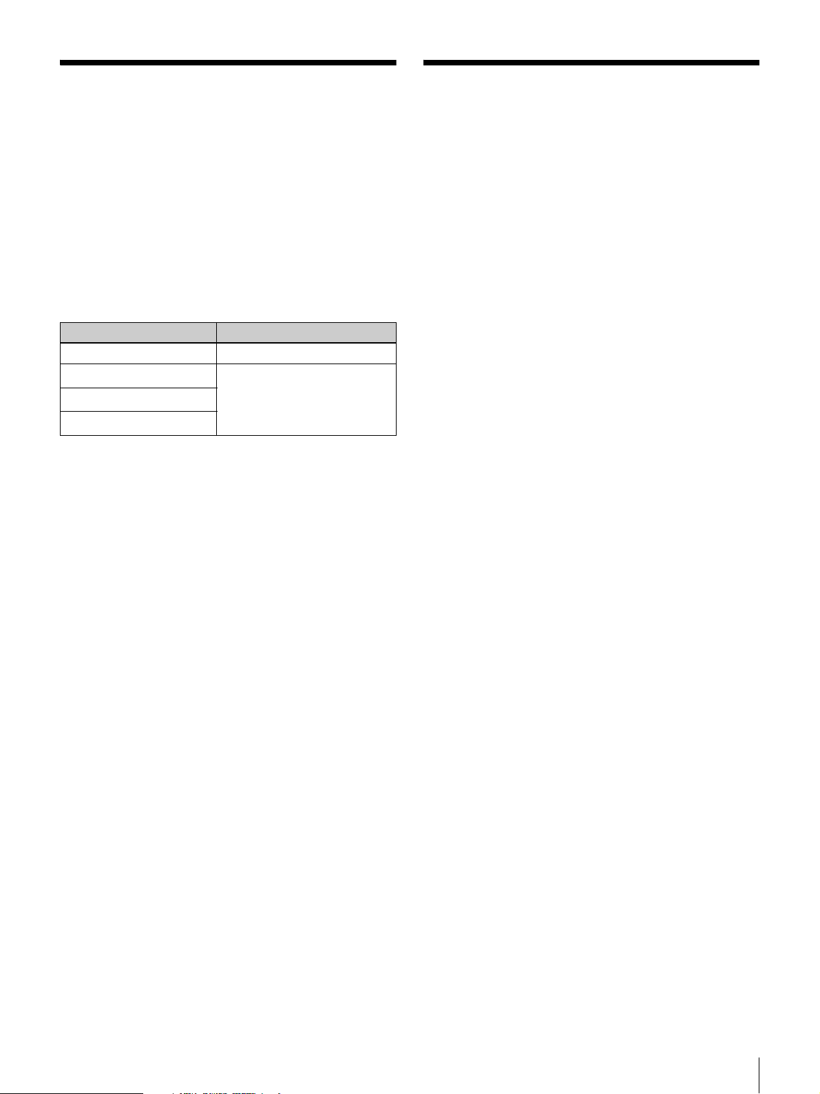
The following table lists the camcorder/camera adaptor
combinations that can be used in the system.
Camcorder Camera adaptor
PMW-EX3 XDCA-53
PMW-350K/350L
PMW-320K/320L
PMW-500
a) An optional CBK-CE01 50 Pin Interface and Digital Extender is required.
b) An optional CBK-HD02 SDI/COMPOSITE Input and 50 Pin Interface is
required.
a)
a)
b)
XDCA-55
Before transmission, this unit can perform format
conversion of video signals received from the camcorder
via the camera adaptor. You can also supply power to the
camcorder from this unit, by connecting this unit and the
camera adaptor with a special power cable (CCZ-A cable).
HD digital transmission
This unit supports bidirectional transmission of
uncompressed HD digital signals between this unit and a
camera adaptor.
The maximum transmission distance is 100 m (328 feet).
You can transmit high-quality video signals regardless of
cable length.
Internal downconverter
You can convert HD signals received from the camera
adaptor to SD output signals.
Internal upconverter
When return video is SD signals, you can upconvert it to
HD signals for transmission to the camera adaptor.
External sync signals
You can genlock this unit to sync signals input from an
external device.
As the external sync signals, you can use either HD
tri-level sync or SD sync signals (black burst).
Communication and control interfaces
• Intercom
• Tally (red and green)
• Trunk line (one line)
• Remote control line
Rack mountable
You can mount this unit in an EIA standard 19-inch rack.
Overview / Features
7
Page 8

Using the CD-ROM
The supplied CD-ROM contains PDF-format Operating
Instructions manuals (in English, Japanese, French,
German, Italian, Spanish, and Chinese) for this unit and
two camera adaptors (XDCA-53 and XDCA-55).
Reading the CD-ROM Manuals
Preparations
The following program must be installed on your computer
in order to read the documents contained on the CD-ROM.
Adobe Reader Version 6.0 or higher
Memo
If Adobe Reader is not installed, you can download it from
the following URL:
http://www.adobe.com/
Adobe and Adobe Reader are trademarks of Adobe Systems Incorporated in
the United States and/or other countries.
To read the documents
Do the following:
1
Insert the CD-ROM in your CD-ROM drive.
A cover page appears automatically in your browser.
If it does not appear automatically in the browser,
double-click on the index.htm file on the CD-ROM.
2
Select and click on the manual that you wish to read.
This opens the PDF file.
Memo
The files may not be displayed properly, depending on the
version of Adobe Reader. In such a case, install the latest
version you can download from the URL mentioned in
“Preparations” above.
Note
If you have lost or damaged the CD-ROM, you can
purchase a new one to replace it. Contact a Sony service
representative.
8
Using the CD-ROM
Page 9

Example System Configurations
The following sections provide examples to show how a
system can be configured.
System including the PMW-320/350/500 and XDCA-55
DXF-C50W/51
Viewfinder
PMW-320/350/500
(with the XDCA-55
attached)
Intercom headset
VCT-U14 Tripod
adaptor
Portable camera
tripod
BNC cable (max. 100 m (328 feet))
CCZ-A cable (max. 100 m (328 feet))
System Including the PMW-EX3 and XDCA-53
Return video input
Reference sync signal input
AC power
This
unit
Intercom headset
RM-B150/B750
Remote control unit
RCP-700/900/1000 series
Remote control panel
XLR 5-pin cable
8-pin cable
Video monitor
To switcher
Compact-size LCD monitor
PMW-EX3 (with the
XDCA-53 attached,
optional camcorder
support)
Portable camera
tripod
VCT-U14 Tripod
adaptor
Reference sync signal input
AC power
Intercom headset
BNC cable (max. 100 m (328 feet))
CCZ-A cable (max. 100 m (328 feet))
XLR 5-pin cable
Return video input
This
unit
Intercom headset
RM-B150/B750
Remote control unit
RCP-700/900 series
Remote control panel
XLR 4-pin cable
8-pin cable
Video monitor
To switcher
Example System Configurations
9
Page 10

Note
To check return video signals on the PMW-EX3, you must
mount a monitor on the PMW-EX3 or XDCA-53.
For information about mountable monitors, contact your
dealer or a Sony service representative.
10
Example System Configurations
Page 11

Names and Functions of Parts
Front Panel
1 TALLY lamp
2 POWER switch
3 POWER indicator
4 Camera adaptor indicator
5 CALL button
System setting switches (see page 12)
9 LINK indicator
6 INTERCOM LEVEL knob
7 INTERCOM MIC switch
8 INTERCOM connector
a TALLY lamp (red/green)
Lights in red when a red tally signal is received, and lights
in green when a green tally signal is received.
You can attach one of the supplied number plates above
the lamp (page 18).
b POWER switch
Powers the unit on when pressed on the “"” side, and
powers the unit off when pressed on the “a” side.
c POWER indicator
Lights in green when the unit is powered on.
This unit is equipped with a cooling fan. If the fan fails,
this indicator flashes. In this case, power the unit off
immediately and contact your dealer or a Sony service
representative.
d Camera adaptor indicator
Lights in green when power is being supplied from this
unit to a camera adaptor.
e CALL button
Calls the operator of a camcorder or remote control panel.
When pressed, this button lights in red. At the same time,
the TALLY (red) or CALL lamps on devices in the system
light.
This button also lights in red whenever the CALL button is
pressed on any other device in the system.
Note
When the CALL button is pressed, the behavior of TALLY
(red) or CALL lamps on other devices depends on the
specific devices and on the way that they are combined.
For details, refer to the instruction manuals of the other
devices.
f INTERCOM LEVEL knob
Adjusts the receiver volume level of the headset connected
to the INTERCOM connector.
g INTERCOM MIC switch
Controls the headset microphone connected to the
INTERCOM connector, turning it on or off as required.
ON: Turns the headset microphone on.
OFF: Turns the headset microphone off.
PTT: Turns the headset microphone on for as long as the
switch is held in this position.
h INTERCOM connector (XLR 5-pin)
Allows you to connect an XLR 5-pin type headset.
Dynamic microphones are supported.
The pin assignments are as follows.
Pin number Signal name
1 INCOM MIC GND
2 INCOM MIC IN
3 INCOM RECEIVE GND
4 INCOM RECEIVE OUT
5 Not used
Names and Functions of Parts
11
Page 12

i LINK indicator
Lights in green when a data transfer link between this unit
and a camera adaptor has been established, and when
device authentication between the camera adaptor and the
camcorder has been established.
System setting switches
Use the supplied front cover to protect the system setting
switches from misoperation.
Check the setting of the individual switches and change the
switch setting as required, then attach the front cover to the
Front cover
Front cover attachment screws
SYSTEM SETUP switches
Set up the system format of this unit (number of system
lines/frame rate) to match the system format of the
camcorder.
front panel of the unit with the supplied front cover
attachment screws.
Switch name Settings Description
1080i/720p 1080i: Interlace mode, 1080
59.94/50 59.94: 59.94 Hz (NTSC area)
lines
720p: Progressive mode, 720
lines
50: 50 Hz (PAL area)
For details, see “Setting the System Format” (page 19).
OUTPUT SELECT switches
Make settings related to the output signals of this unit.
Switch name Settings Description
HD/SD HD: HDSDI signals
SD: SDSDI signals
WIDE ID ON: Add a wide ID signal when
SETUP (NTSC
area only)
the aspect ratio is 16:9, and
do not add a wide ID signal
when the aspect ratio is 4:3
OFF: Never add a wide ID signal
ON: Add setup
OFF: Do not add setup
Sets the number of system lines.
Sets the system frequency.
Selects the type of signals output from the
OUTPUT SDI connectors of this unit.
Specifies whether to add a wide ID signal
to composite signals output from the
VIDEO OUTPUT and REMOTE
connectors, and to SDSDI signals output
from the OUTPUT SDI connectors.
When you are using the unit in an NTSC
area, specifies whether to add a 7.5%
setup to the composite signals output from
the VIDEO OUTPUT and REMOTE
connectors.
DOWN CONVERTER ADJUSTMENT switches
Specify the methods used to adjust down converted
signals. These adjustments are applied to SDSDI signals
output from the OUTPUT SDI connectors and to SD
analog composite signals output from the VIDEO
OUTPUT and REMOTE connectors.
12
Names and Functions of Parts
Note
The settings of these switches do not affect the signals
output from the OUTPUT SDI connectors when those
signals are HDSDI signals.
Page 13

Switch name Settings Description
ASPECT SQUEEZE: Squeeze mode
DETAIL LEVEL HIGH: High
CROSS COLOR
SUPPRESSION
RETURN INPUT SELECT switches
Make settings related to return video signals.
Switch name Settings Description
HDSDI/SDSDI/
VIDEO
AUTO/
SQUEEZE/
LETTER BOX/
EDGE CROP
LETTER BOX: Letter box mode
EDGE CROP: Edge crop mode
MID: Middle
LOW: Low
ON: Enabled
OFF: Disabled
HDSDI: Use the HDSDI signal
input from the RETURN INPUT
SDI connector as the return
video signal
SDSDI: Use the SDSDI signal input
from the RETURN INPUT SDI
connector as the return video
signal
VIDEO: Use the SD analog
composite signal input from the
RETURN INPUT VIDEO
connector as the return video
signal
AUTO: Determine the conversion
mode automatically on the basis
of the wide ID signal added to
the input return video signal.
When the input is 4:3, and when
a wide ID signal cannot be
detected, convert using Edge
Crop. When the input is 16:9,
convert using Squeeze.
SQUEEZE: Use Squeeze (16:9) to
process the input return video
signal, and leave the signal as
Squeeze.
LETTER BOX: Use Letter Box to
process the input return video
signal. Convert the signal to
16:9, with the top and bottom
sides cut.
EDGE CROP: Use Edge Crop (4:3)
to process the input return video
signal. Convert the signal to
16:9, with black at both edges.
Specifies the conversion mode.
Selects the detail level (the
degree of edge emphasis applied
to the shooting subject) from
among three stages.
Enables or disables the cross
color suppression function of the
down converter.
Selects the type of return video
signal input to this unit.
Specifies the conversion mode
used to up convert SD return video
signals input to this unit to HD
signals.
Note
When an HDSDI signal is selected
as the return video signal, the
setting of this switch does not affect
the return video signal input.
For details, see “Return Video Signal Input and Output”
(page 21).
Names and Functions of Parts
13
Page 14

INTERCOM IF switch
Switch name Settings Description
INTERCOM IF 4W: Select this when you are using
a 4-wire system
2W C.C: Select this when you are
using a 2-wire Clear-Com
system
2W RTS: Select this when you are
using a 2-wire RTS system
Specifies the type of intercom
system connected to the AUX
connector of this unit.
Note
If you have not connected an intercom system to the AUX
connector of this unit, always set this item to “4W”.
Rear Panel
1 REMOTE connector
2 AUX connector
3 GENLOCK INPUT connectors
4 OUTPUT SDI
connectors
9 RETURN INPUT SDI connector
q; RETURN INPUT VIDEO connector
qa VIDEO OUTPUT connector
If you set it to anything other than “4W”, the intercom
system may not operate properly.
For information about connections to an intercom system,
contact your dealer or a Sony service representative.
5 CA connector
6 - AC IN connector
7 CA OUT connector
8 CA IN connector
a REMOTE connector (8-pin round)
Connect to a remote control unit using a connection cable.
This connector is used to exchange control signals with the
camcorder.
Provides a trunk line connection to the trunk line of the
camera adaptor via a RS-232C interface, for use as a
communications line with external devices. Also equipped
with general-purpose lines between this unit and the
camera adaptor.
b AUX connector (D-sub 25-pin)
The pin assignments are as follows.
Connect to an external system to input and output intercom
signals, tally signals, trunk line signals, and timecode.
Pin number Signal name Description
1 GND Ground
2 TRUNK TX Trunk line (RS-232C, up to 38.4 kbps)
3 TRUNK RX
6 TC IN Timecode signal input
16 AUX1 General-purpose line 1 between this unit and the camera adaptor
17 AUX2 General-purpose line 2 between this unit and the camera adaptor
9 AUX VIDEO(X) General-purpose analog video line between this unit and the
8 AUX VIDEO(G)
14
Names and Functions of Parts
camera adaptor
Page 15

Pin number Signal name Description
7 TALLY(GND) Tally input
14 G TALLY IN
15 R TALLY IN
11 4W(G) 4-wire interface system output
13 4W(X)OUT
12 4W(Y)OUT
18 4W(G) 4-wire interface system input
19 4W(X)IN
21 4W(Y)IN
10 CLEAR COM(X)IN/OUT Clear-Com system interface (requires termination, recommended
23 CLEAR COM(G)
25 RTS IN/OUT RTS system interface (requires termination, recommended
24 RTS(G)
20 NC Not used
22 NC
4 Reserved Pins reserved for maintenance
5Reserved
On: GND
Off: Open
impedence 200 Ω)
impedence 200 Ω)
c GENLOCK INPUT connectors (BNC type)
Input an external sync signal, either an HD tri-level
reference sync signal or an SD reference sync signal (black
burst signal). The two connectors have a loop-through
configuration. The signal input to the input side connector
is output unchanged to the output side connector ( ).
When nothing is connected to the output side connector,
the input signal is terminated automatically (75
Ω
termination).
d OUTPUT SDI connectors (BNC type)
Output video, audio, and timecode received from the
camcorder via the camera adaptor is output as HDSDI or
SDSDI signals.
e CA (camera adaptor) connector (CCZ 26-pin)
Connect to the CEU connector of the camera adaptor with
a optional CCZ-A cable. This cable supplies DC power to
the camcorder via the camera adaptor.
This connector also provides general-purpose lines
between this unit and the camera adaptor.
For details about the general purpose lines, see “AUX
connector” (page 14).
For details about the pin assignments of the CA connector,
contact a Sony service representative.
g CA OUT (camera adaptor output) connector (BNC
type)
Connect to the CEU IN connector of the camera adaptor
using a BNC cable.
h CA IN (camera adaptor input) connector (BNC
type)
Connect to the CEU OUT connector of the camera adaptor
using a BNC cable.
i RETURN INPUT SDI connector (BNC type)
Input HDSDI or SDSDI return video signals.
For details, see “Return Video Signal Input and Output”
(page 21).
j RETURN INPUT VIDEO connector (BNC type)
Input SD analog composite return video signals.
For details, see “Return Video Signal Input and Output”
(page 21).
k VIDEO OUTPUT connector (BNC type)
Output video signals received from the camcorder via the
camera adaptor as SD analog composite signals.
The following table lists the signal formats of the SD
analog composite signals output from this connector.
f - AC IN connector (3-pin)
Connect to an AC power source with the specified power
cable.
System format (number of
system lines/frame rate)
1080/59.94i NTSC (525/59.94i)
720/59.94P
Signal format
Names and Functions of Parts
15
Page 16

System format (number of
system lines/frame rate)
1080/50i PAL (625/50i)
720/50P
Signal format
The SD analog composite signals output from this
connector and the video output pin of the REMOTE
connector, and the SDSDI signals output from the
OUTPUT SDI connector, are SD signals that have been
internally down converted from HD signals by this unit.
16
Names and Functions of Parts
Page 17

Preparations and Settings
Example Connections
Connecting to the XDCA-55
CCZ-A cable (Max. 100 m (328 feet))
This unit
BNC cable
XDCA-55
PMW-320/350/500
Connecting to the XDCA-53
CCZ-A cable (Max. 100 m (328 feet))
This unit
BNC cable
XDCA-53
PMW-EX3
BNC cable
BNC cable
To fix the connection cables using the
cable clamp belt
The cables to connect this unit and the camera adaptor can
be fixed to the camera or plate by using the cable clamp
belt supplied with the camera adaptor.
When the camera adaptor is the XDCA-55
1
Attach the cable clamp belt (supplied with the
XDCA-55) to the XDCA-55 using the belt bracket
attachment screw holes at the side of XDCA-55.
Preparations and Settings
17
Page 18

Belt bracket attachment screws (XDCA-55)
2
Bundle the three connection cables with the cable
clamp belt. Pass the cables as illustrated.
Belt bracket
(supplied with XDCA-55)
Cable clamp belt (supplied with XDCA-55)
2
Bundle the three connection cables with the cable
clamp belt. Pass the cables so as to make a loop as
illustrated.
3
Adjust the tightening force of the belt to suit the
diameters of the cables.
Adjust the tightening force of the belt to suit the
diameters of the cables.
To this unit
Cable clamp belt (supplied with XDCA-53)
Attaching Rack Mount Brackets
You can attach the supplied rack mount brackets and
mount this unit on a rack. This allows other devices to be
mounted above and below this unit without impeding
adequate heat dissipation.
To this unit
Cable clamp belt (supplied with XDCA-55)
When the camera adapator is the XDCA-53
1
Attach the cable clamp belt (supplied with the
XDCA-53) to the right side (as viewed from the
XDCA-53) of the plate.
Cable clamp belt (supplied with XDCA-53)
Plate
Belt bracket attachment
screws (XDCA-53)
Belt bracket (supplied
with XDCA-53)
Exchanging the Number Plate of the
Tally Lamp
Using a flat-blade screwdriver, you can exchange the
TALLY lamp number plate as shown in the figure below.
18
Preparations and Settings
Page 19

Starting the System
Notes
• After connecting the system with a CCZ-A and BNC
cables, power on the devices as described below.
• Do not connect or disconnect the cables connecting this
unit and the camera adaptor (CCZ-A and BNC cables)
while the system is powered on. The excessive current
protection function may be activated, cutting off power
to the power circuits of this unit or the camera adaptor.
If the power should be cut off, connect the cables again
in the proper fashion and wait for a while before starting
the system again.
When using the XDCA-55 and PMW-320/
350/500
Set the POWER switch of the PMW-320/350/500 to the
ON position, and then press the “"” side of the POWER
switch of this unit.
This unit starts.
Power is supplied from this unit to the XDCA-55, and the
PMW-320/350/500 starts.
When using the XDCA-53 and PMW-EX3
1
Set the power switch of the PMW-EX3 to the
CAMERA side.
2
Press the “"” side of the POWER switch of the
XDCA-53.
3
Press the “"” side of the POWER switch of this unit.
This unit starts.
Power is supplied from this unit to the XDCA-53, and
the PMW-EX3 starts in camera mode.
Note
Always start the PMW-EX3 in camera mode.
To shut down the system
Press the “a” side of the POWER switch of this unit to
power the entire sytem off.
Notes
• This unit designed for use with bi-directional HD digital
transmission systems. It does not function if the
camcorder side is set to SD mode.
In the same way, this unit does not function if the
camcorder is set to HD mode with a frame rate of 23.98P
but the SDI OUTPUT setting is SD.
For details, refer to the operating instructions of your
camcorder for details about operating mode settings.
• This unit’s TALLY lamp flashes if the system format of
this unit and that of the camcorder are different. Device
authentication between the camera adaptor and the
camcorder is not established, so the LINK indicator does
not light.
For details, see “Alarms (when the XDCA-55 is used)”
(page 21).
Camcorder System format
Operating
mode
HD mode
(HDSDI output)
SD mode
(SDSDI output)
Video format
1920×1080/59.94i 1080/59.94i
1920×1080/29.97PsF
1280×720/59.94P 720/59.94P
1920×1080/50i 1080/50i
1920×1080/25P
1280×1080/50P 720/50P
1920×1080/23.98P Not supported
720×486/59.94i
720×576/50i
of this unit
Set the system format of this unit by setting the SYSTEM
SETUP switches as follows.
System
format
1080/59.94i 59.94 1080i
720/59.94P 720P
1080/50i 50 1080i
720/50P 720P
59.94/50 switch
setting
1080i/720P
switch setting
Setting the System Format
To record and transmit with this system, set the system
format (number of system lines/frame rate) of this unit as
shown in the table below to match the video format
settings of the camcorder.
Preparations and Settings
19
Page 20

Genlocking the System
To genlock the system, input a reference sync signal to the
input side GENLOCK INPUT connector of this unit. The
reference sync signal can be an analog HD signal (tri-level
sync) or an analog SD signal (bi-level sync).
This unit detects the signal format of the input reference
sync signal automatically and determines whether that
signal can be used as reference sync signal, according to
the current system format.
The reference sync signal input to the input side
GENLOCK INPUT connectors is output from the
loop-through output side connector ( ).When nothing is
The following table lists the formats of usable reference
sync signals.
connected to the output side connector, the reference sync
signal is terminated automatically (75
System format Reference sync signal formats (total number of system lines/frame rate)
1125/59.94i 750/59.94P 1125/50i 750/50P 525/59.94i 625/50i
1080/59.94i a –––a –
720/59.94P aa ––a –
1080/50i – – a ––a
720/50P – – aa– a
a: Yes –: No
When reference sync signals are not input to this unit, the
system operates with this unit as the master. The
camcorder operates in synchronization to reference sync
signals input from the camera adaptor.
Ω termination).
To set the H phase of HD/SD output
When the system is genlocked, and the H phase of HD/SD
output from the camcorder is set to ±0, the H phase of
HDSDI or SDHDI signals output from the OUTPUT SDI
connectors of this unit matches the phase of reference sync
signals input to this unit.
The HD/SD switch (one of the OUTPUT SELECT
Note
The system is not synchronized when the camcorder is
operating in a special recording mode or playback mode.
switches) can be used to set the H phase of SD analog
composite signals output from the video output pins of the
VIDEO OUTPUT and REMOTE connectors, as shown in
the following table.
HD/SD switch setting Output signal Phase difference with reference sync signal
HD HDSDI ±0H
SD analog composite +90H
SD SDSDI ±0H
SD analog composite ±0H
20
Preparations and Settings
Page 21

Appendix
Return Video Signal Input and Output
Return video signals input to this unit are sent to the
camera adaptor as HDSDI signals. The camera adaptor
switches between the return video signal received from
this unit and the signal received from the camcorder, and
outputs the signal from the MONI.OUT connector. The
XDCA-55 sends return video received from this unit to the
camcorder via its camcorder connection connector
(50-pin).
As return video signals, this unit accepts HDSDI signals,
SDSDI signals, and SD analog composite signals. HDSDI
and SDSDI return video signals are input from the unit’s
System
format
1080/59.94i a
720/59.94P
1080/50i
720/50P
a: Yes –: No
Formats of return video signals that can be input to this unit
HDSDI SDSDI SD analog composite
1080/59.94i 720/59.94P 1080/50i 720/50P 486/59.94i 576/50i 525/59.94i 625/50i
–––
–
––
–––
a
––
a
––
a
When a return video signal is input to this system, and that
signal in not synchronized with this system, you can
RETURN INPUT SDI connector. SD analog composite
return video signals are input from the unit’s RETURN
INPUT VIDEO connector. Use the HDSDI/SDSDI/
VIDEO switch (one of the RETURN INPUT SELECT
switches) to select which of these signals to use as the
return video signal (see page 13).
The format of the return video signals that can be input to
this unit varies as shown in the following table, according
to the system format settings of this unit and the
camcorder.
a
a
–
–
–
a
a
a
a
–
–
–
–
a
a
synchronize it by using the internal frame synchronizer of
this unit.
Switching the Monitor Output of the XDCA-55/XDCA-53
The monitor output from the MONITOR OUT (SDI)
connector of the XDCA-55 or MONITOR OUT connector
and MONI.OUT (SDI) connector of the XDCA-53 can be
switched between return video signals sent from this unit
and the shooting or playback signals sent from the
camcorder.
MONI. SEL switch RET button state Monitor output
RET On (the RET button is pressed on one of the
devices in the system)
Off (the RET button is not pressed)
CAM/RET On (the RET button is pressed on one of the
devices in the system)
Off (the RET button is not pressed) Shooting or playback signals sent from the camera
Alarms (when the XDCA-55 is used)
The TALLY lamp (red) flashes as an alarm if the system
frequencies of this unit and the camcorder are different.
The monitor output from the XDCA-55/53 is switched as
shown in the following table, according to the settings of
the MONI. SEL switch and the RET button on the camera
adaptor.
Return video signal
Even if the TALLY lamp is already lit, it changes to
flashing if an alarm occurs.
For details about the system frequency of this unit and that
of the camcorder, see “Setting the System Format”
(page 19).
Appendix
21
Page 22

Fan alarms
The POWER indicator flashes at a frequency of 4 Hz when
the unit’s cooling fan is not rotating during operation of the
unit.
Important Notes on
Operation
Use and storage locations
Avoid using or storing the unit in the following places.
• In excessive heat or cold (operating temperature range:
5°C to 40°C (41°F to 104°F))
• Remember that in summer in warm climates the
temperature inside a car with the windows closed can
easily exceed 50°C (122°F).
• In damp or dusty locations
• Locations where the unit may be exposed to rain
• Locations subject to violent vibration
• Near strong magnetic fields
• Close to radio or TV transmitters producing strong
electromagnetic fields
• In direct sunlight or close to heaters for extended periods
Do not subject to strong shocks
Do not drop the unit or subject it to strong shocks. The unit
may be damaged.
Do not wrap in a cloth or other covering during
operation
Internal temperatures may rise, causing malfunctions.
Maintenance
Clean the cabinet and panels by wiping lightly with a soft,
dry cloth. If they are very dirty, use a cloth dampened with
a small amount of neutral detergent, then wipe dry. Avoid
the use of volatile solvents such as thinners, alcohol,
benzene, and insecticides. They may damage the surface
finish or cause it to peel off.
22
Important Notes on Operation
Page 23

Specifications
General
Power requirements
100 V to 240 V AC, 50/60 Hz
Power consumption
Max. 1.6 A (during operation of entire
system, 100 V to 240 V AC)
Note
The total current consumption on the
camcorder and camera adapter (including
peripheral equipment) to receive power
from this unit must not exceed 70 W.
Peak inrush current
(1) Power ON, current probe method: 8 A
(100 V), 40 A (240V)
(2) Hot switching inrush current,
measured in accordance with
European standard EN55103-1: 14 A
(230 V)
Operating temperature
5°C to 40°C (41°F to 104°F)
Operating humidity
20% to 90%
Storage temperature
–20°C to +55°C (–4°F to +131°F)
Dimensions (w/h/d, excluding projections)
424 × 44 × 290 mm (16
inches)
Mass Approx. 3.5 kg (7 lb 7.7 oz)
Connectors
Input connectors
RETURN INPUT SDI
BNC type, 0.8 Vp-p, 75 Ω
RETURN INPUT VIDEO
BNC type, VBS (1.0 Vp-p), 75 Ω
GENLOCK INPUT
BNC type (2), loop-through input, 75 Ω
automatic termination
HD tri-level sync or black burst
3
/4 × 13/4 × 111/
Camera adaptor input/output connectors
CA IN/OUT BNC type (1 each), 0.8 Vp-p, 75 Ω
CA CCZ 26-pin (1), male
Other connectors
INTERCOM XLR 5-pin (1), female
AUX D-sub 25-pin (1), female
REMOTE 8-pin round (1), female
Supplied Accessories
Operating Instructions
Japanese (1)
English (1)
CD-ROM (1)
Rack mount brackets (2)
Rack mount bracket attachment screws (4)
Front cover (1)
Front cover attachment screws (2)
Numbr plates (1 set)
Accessories Not Supplied
United States and Canada: Plug holder B (2-990-242-01)
Other areas: Plug holder C (3-613-640-01)
United States and Canada: Power cord set (1-551-812-XX)
Other areas: Power cord set (1-782-929-XX)
CCZ-A cable (CCZ-A5 (5 m), CCZ-A10 (10 m),
CCZ-A25 (25 m), CCZ-A50 (50 m), CCZ-A100
(100 m))
Design and specifications are subject to change without
2
notice.
Note
Always verify that the unit is operating properly before
use. SONY WILL NOT BE LIABLE FOR DAMAGES
OF ANY KIND INCLUDING, BUT NOT LIMITED
TO, COMPENSATION OR REIMBURSEMENT ON
ACCOUNT OF THE LOSS OF PRESENT OR
PROSPECTIVE PROFITS DUE TO FAILURE OF
THIS UNIT, EITHER DURING THE WARRANTY
PERIOD OR AFTER EXPIRATION OF THE
WARRANTY, OR FOR ANY OTHER REASON
WHATSOEVER.
Output connectors
VIDEO OUTPUT
BNC type (1), VBS: 1.0 Vp-p, sync
negative, 75 Ω, unbalanced
OUTPUT SDI BNC type (1 each), 0.8 Vp-p, 75 Ω
Specifications
23
Page 24

Printed in China
 Loading...