

Sony XDCAM PMW-500 Operation Manual

SOLID-STATE MEMORY CAMCORDER
PMW-500
OPERATION MANUAL [English]
1st Edition (Revised 2)

WARNING
To reduce the risk of fire or
electric shock, do not
expose this apparatus to
rain or moisture.
To avoid electrical shock,
do not open the cabinet.
Refer servicing to qualified
personnel only.
Important Safety Instructions
• Read these instructions.
• Keep these instructions.
• Heed all warnings.
• Follow all instructions.
• Do not use this apparatus near water.
• Clean only with dry cloth.
• Do not block any ventilation openings.
Install in accordance with the
manufacturer’s instructions.
• Do not install near any heat sources such
as radiators, heat registers, stoves, or
other apparatus (including amplifiers) that
produce heat.
• Do not defeat the safety purpose of the
polarized or grounding-type plug. A
polarized plug has two blades with one
wider than the other. A grounding-type
plug has two blades and a third grounding
prong. The wide blade or the third prong
are provided for your safety. If the
provided plug does not fit into your outlet,
consult an electrician for replacement of
the obsolete outlet.
• Protect the power cord from being walked
on or pinched particularly at plugs,
convenience receptacles, and the point
where they exit from the apparatus.
• Only use attachments/accessories
specified by the manufacturer.
• Refer all servicing to qualified service
personnel. Servicing is required when the
apparatus has been damaged in any way,
such as power-supply cord or plug is
damaged, liquid has been spilled or
objects have fallen into the apparatus, the
apparatus has been exposed to rain or
moisture, does not operate normally, or
has been dropped.
WARNING
Excessive sound pressure from earphones
and headphones can cause hearing loss.
In order to use this product safely, avoid
prolonged listening at excessive sound
pressure levels.
For the customers in the U.S.A.
This equipment has been tested and found
to comply with the limits for a Class B digital
device, pursuant to Part 15 of the FCC
Rules. These limits are designed to provide
reasonable protection against harmful
interference in a residential installation. This
equipment generates, uses, and can radiate
radio frequency energy and, if not installed
and used in accordance with the
instructions, may cause harmful interference
to radio communications. However, there is
no guarantee that interference will not occur
in a particular installation. If this equipment
does cause harmful interference to radio or
television reception, which can be
determined by turning the equipment off and
on, the user is encouraged to try to correct
the interference by one or more of the
following measures:
- Reorient or relocate the receiving
antenna.
- Increase the separation between the
equipment and receiver.
- Connect the equipment into an outlet on a
circuit different from that to which the
receiver is connected.
- Consult the dealer or an experienced
radio/TV technician for help.
You are cautioned that any changes or
modifications not expressly approved in this
manual could void your authority to operate
this equipment.
All interface cables used to connect
peripherals must be shielded in order to
comply with the limits for a digital device
pursuant to Subpart B of Part 15 of FCC
Rules.
If you have any questions about this product,
you may call;
2

Sony Customer Information Service Center
1-800-222-7669 or http://www.sony.com/
Declaration of Conformity
Trade Name : SONY
Model : PMW-500
Responsible party : Sony Electronics Inc.
Address : 16530 Via Esprillo,
San Diego, CA
92127 U.S.A.
Telephone Number : 858-942-2230
This device complies with part 15 of the
FCC Rules. Operation is subject to the
following two conditions: (1) this device
may not cause harmful interference, and
(2) this device must accept any
interference received, including
interference that may cause undesired
operation.
For the customers in Canada
This Class B digital apparatus complies with
Canadian ICES-003.
For the customers in Europe
This product with the CE marking complies
with the EMC Directive issued by the
Commission of the European Community.
Compliance with this directive implies
conformity to the following European
standards:
• EN55103-1: Electromagnetic
Interference(Emission)
• EN55103-2: Electromagnetic
Susceptibility(Immunity)
This product is intended for use in the
following Electromagnetic Environments: E1
(residential), E2 (commercial and light
industrial), E3 (urban outdoors), E4
(controlled EMC environment, ex. TV
studio).
The manufacturer of this product is Sony
Corporation, 1-7-1 Konan, Minato-ku,
Tokyo, Japan.
The Authorized Representative for EMC and
product safety is Sony Deutschland GmbH,
Hedelfinger Strasse 61, 70327 Stuttgart,
Germany.
For the State of California, USA only
Perchlorate Material - special handling may
apply, See
www.dtsc.ca.gov/hazardouswaste/
perchlorate
Perchlorate Material : Lithium battery
contains perchlorate.
For the customers in Taiwan only
3

Table of Contents
Foreword .................................................................................................... 10
Before Use....................................................................................... 10
Mode Indications in This Manual ............................................................ 10
Chapter 1 : Overview
Features ...................................................................................................... 11
Using the Software..................................................................................... 13
Reading the CD-ROM Manuals............................................................... 13
Locations and Functions of Parts and Controls...................................... 14
Power Supply .................................................................................. 14
Accessory Attachments................................................................... 15
Operating and Connectors Section.................................................. 16
LCD Monitor................................................................................... 25
HDVF-20A Viewfinder (Optional)................................................. 27
CBK-VF01 Viewfinder (Optional) ................................................. 28
Status Display on the Viewfinder Screen........................................ 29
Chapter 2 : Preparations
Preparing a Power Supply ........................................................................ 34
Attaching the Viewfinder .......................................................................... 35
Setting the Area of Use .............................................................................. 39
Setting the Date/Time of the Internal Clock ........................................... 40
Mounting and Adjusting the Lens............................................................ 40
Preparing the Audio Input System .......................................................... 42
Table of Contents
4
Using a Battery Pack....................................................................... 34
Using AC Power ............................................................................. 35
Attaching the Viewfinder................................................................ 35
Adjusting the Viewfinder Position.................................................. 36
Using the BKW-401 Viewfinder Rotation Bracket ........................ 36
Detaching the Eyepiece................................................................... 37
Adjusting the Viewfinder Focus and Screen................................... 38
Adjusting the Flange Focal Length................................................. 41
Connecting a Microphone to the MIC IN Connector...................... 42
Connecting Microphones to the AUDIO IN Connectors................ 43

Attaching a UHF Portable Tuner (for a UHF Wireless Microphone
System) ..................................................................................... 44
Connecting Line Input Audio Equipment....................................... 45
Tripod Mounting ....................................................................................... 46
Connecting a Video Light ......................................................................... 47
Using the Shoulder Strap .......................................................................... 48
Adjusting the Shoulder Pad Position....................................................... 49
Chapter 3 : Adjustments and Settings
Setting the Video Format .......................................................................... 50
Selecting the Recording Mode........................................................ 52
Changing the Video Format............................................................ 52
Adjusting the Black Balance and the White Balance............................. 53
Adjusting the Black Balance........................................................... 53
Adjusting the White Balance .......................................................... 54
Setting the Electronic Shutter................................................................... 56
Shutter Modes ................................................................................. 56
Selecting the Shutter Mode and Shutter Speed............................... 56
Changing the Reference Value for Automatic Iris Adjustment............ 58
Adjusting the Audio Level ........................................................................ 59
Manually Adjusting the Audio Levels of the Audio Inputs from the
AUDIO IN CH-1/CH-2 Connectors ......................................... 59
Manually Adjusting the Audio Level of the MIC IN Connector.... 59
Recording Audio on Channels 3 and 4 ........................................... 60
Setting the Time Data................................................................................ 61
Setting the Timecode....................................................................... 61
Setting the User Bits........................................................................ 62
Synchronizing the Timecode........................................................... 62
Setting Shot Data ....................................................................................... 64
Creating a Shot ID........................................................................... 64
Checking Camcorder Settings and Status Information (Status Screens)
............................................................................................................... 65
Chapter 4 : Shooting
Handling SxS Memory Cards................................................................... 67
About SxS Memory Cards .............................................................. 67
Loading and Ejecting SxS Memory Cards...................................... 68
Selecting the SxS Memory Card to Use.......................................... 69
Table of Contents
5

Formatting (Initializing) SxS Memory Cards................................. 69
If You Load a Memory Card Formatted in the Different Recording
Mode from the Mode Selected on the Camcorder.................... 70
Checking the Remaining Recording Time...................................... 70
Restoring SxS Memory Cards......................................................... 71
Handling USB Flash Drives ...................................................................... 72
Formatting (Initializing) USB Flash Drives.................................... 72
Restoring USB Flash Drives ........................................................... 73
Basic Operations........................................................................................ 73
Playing Recorded Clips................................................................... 75
Deleting Recorded Clips ................................................................. 76
Advanced Operations ................................................................................ 76
Recording Shot Marks..................................................................... 76
Setting OK Marks ........................................................................... 77
Starting to Record from Pre-stored Video (Picture Cache Function)
.................................................................................................. 77
Recording Time-lapse Video (Interval Rec Function).................... 78
Shooting Stop Motion Animations (Frame Rec Function) ............. 80
Shooting with Slow & Quick Motion ............................................. 81
Recording with the Clip Continuous Rec Function ........................ 82
Framing Shots with the Freeze Mix Function................................. 83
Recording Proxy Data ............................................................................... 84
Recording Proxy Data While Recording Clips............................... 84
Recording Proxy Data for Existing Clips........................................ 85
Deleting All Proxy Data from a USB Flash Drive.......................... 85
Planning Metadata Operations ................................................................ 86
Loading a Planning Metadata File into Camcorder’s Internal Memory
.................................................................................................. 86
Defining Clip Names in Planning Metadata ................................... 87
Defining Shot Mark Names in Planning Metadata ......................... 89
Chapter 5 : Clip Operations
Clip Playback ............................................................................................. 90
Thumbnail Operations.............................................................................. 95
Table of Contents
6
Thumbnail Screen ........................................................................... 90
Playing Clips................................................................................... 93
Using Thumbnails to Search Inside Clips....................................... 94
THUMBNAIL Menu Configuration............................................... 95
Basic THUMBNAIL Menu Operations.......................................... 97
Changing the Thumbnail Screen Type............................................ 97
Displaying Clip Properties .............................................................. 99
Adding and Deleting OK, NG or KP Marks................................. 100

Protecting Clips............................................................................. 101
Copying Clips ............................................................................... 101
Deleting Clips................................................................................ 102
Displaying the Expand Thumbnail Screen.................................... 103
Displaying the Essence Mark Thumbnail Screen ......................... 104
Adding and Deleting Shot Marks.................................................. 105
Changing Clip Index Pictures ....................................................... 105
Dividing Clips............................................................................... 105
Chapter 6 : Menu and Detailed Settings
Setup Menu Organization and Levels.................................................... 106
Setup Menu Organization ............................................................. 106
Setup Menu Levels........................................................................ 106
Basic Setup Menu Operations ................................................................ 108
Menu List.................................................................................................. 110
USER Menu (Factory Default Configuration).............................. 110
OPERATION Menu...................................................................... 111
PAINT Menu................................................................................. 128
MAINTENANCE Menu............................................................... 134
FILE Menu.................................................................................... 149
Assigning Functions to Assignable Switches ......................................... 154
Functions That Can Be Assigned to the ASSIGN. 0 Switch ........ 154
Functions That Can Be Assigned to the ASSIGN. 2 Switch ........ 155
Functions That Can Be Assigned to the ASSIGN. 1 and 3 Switches,
the ASSIGNABLE 4 and 5 Switches, and the COLOR TEMP.
Button...................................................................................... 155
Functions That Can Be Assigned to the RET Button on the Lens 158
Chapter 7 : Saving and Loading User Setting Data
Saving and Loading Settings................................................................... 159
Saving Setting Data....................................................................... 159
Loading Setting Data..................................................................... 160
Resetting a File after Changing Its Contents................................. 161
Saving and Loading Scene Files ............................................................. 161
Saving Scene Files ........................................................................ 161
Loading Scene Files...................................................................... 162
Saving and Loading Lens Files............................................................... 163
Setting Lens File Data................................................................... 163
Saving Lens Files.......................................................................... 163
Loading Lens Files........................................................................ 163
Table of Contents
7

Loading Lens Files Automatically................................................ 164
Saving and Loading User Files............................................................... 164
Saving User Files .......................................................................... 164
Loading Setting Data..................................................................... 165
Chapter 8 : Connecting External Devices
Connecting External Monitors ............................................................... 166
Operating Clips with a Computer.......................................................... 168
Using the ExpressCard Slot of a Computer .................................. 168
USB Connection with a Computer................................................ 168
Connecting an External Device (i.LINK Connection).......................... 170
Recording the Camera Picture on an External Device.................. 170
Nonlinear Editing.......................................................................... 171
Recording External Input Signals ................................................. 171
Configuring a Shooting and Recording System.................................... 172
Chapter 9 : Maintenance
Testing the Camcorder............................................................................ 173
Maintenance............................................................................................. 173
Cleaning the Viewfinder ............................................................... 173
Note about the Battery Terminal................................................... 174
Operation Warnings................................................................................ 175
Error Indication............................................................................. 175
Warning Indication........................................................................ 176
Appendix
Table of Contents
8
Important Notes on Operation ............................................................... 183
Exchanging the Battery of the Internal Clock ...................................... 185
Specifications............................................................................................ 185
General.......................................................................................... 185
Camera Block................................................................................ 186
Audio Block .................................................................................. 187
Display .......................................................................................... 187
Media Block.................................................................................. 187
Inputs/Outputs............................................................................... 187
Supplied Accessories .................................................................... 188
Recommended Additional Equipment.......................................... 188

Chart of Optional Components and Accessories .................................. 190
About i.LINK ........................................................................................... 191
MPEG-4 Visual Patent Portfolio License .............................................. 192
MPEG-2 Video Patent Portfolio License............................................... 192
About Bitmap Fonts ................................................................................ 192
About OpenSSL ....................................................................................... 193
Index.......................................................................................................... 196
Table of Contents
9

Foreword
Mode Indications in This Manual
Before Use
After purchasing the PMW-500 Solid-State
Memory Camcorder, before operating, it is
necessary to set the area of use.
(Unless this setting is made, the camcorder will
not operate.)
For details of these settings, see “Setting the Area of
Use” (page 39).
Note
Before attaching/removing optional components or
accessories to/from the PMW-500 (referred to as “the
camcorder”), be sure to turn the power of the camcorder
off.
Some functions and information are available
only when this camcorder is in a specific
operating mode. This manual indicates those
modes by using the following marks. When these
marks appear, the associated function or
information is available only in that mode.
HD
HD mode: When OPERATION >Format >HD/
SD in the setup menu is set to [HD].
UDF
UDF mode: When OPERATION >Format >File
System in the setup menu is set to [UDF].
FAT
FAT mode: When OPERATION >Format >File
System in the setup menu is set to [FAT].
FAT-H D
FAT-HD mode: When OPERATION >Format
>File System in the setup menu is set to [FAT]
and OPERATION >Format >HD/SD in the setup
menu is set to [HD].
FAT-S D
FAT-SD mode: When OPERATION >Format
>File System in the setup menu is set to [FAT]
and OPERATION >Format >HD/SD in the setup
menu is set to [SD].
Foreword / Mode Indications in This Manual
10

Chapter1 Overview
Features
2
/3-inch full-HD “PowerHAD FX” CCDs
• IT (Interline Transfer) 2/3-inch progressive
image sensors with 207 million pixels, for full
HD resolution (1920 × 1080)
• “PowerHAD FX” CCDs, featuring a signal
processing ASIC with 14-bit A/D converters
These new image sensor technologies enable
the capture of very high-quality images, with
F11 (59.94i) and F12 (50i) sensitivity and an
SN ratio of 59 dB.
1) With noise suppression on (off value is 54 dB) Noise
suppression uses proprietary Sony signal processing
technology to suppress noise in highfrequency
regions.
SxS memory cards as recording media
Using SxS memory cards, the camcorder offers
nonlinear capabilities such as instant random
access and file-based operation.
You can choose FAT or UDF as the file system
for recording media.
1)
For recording in FAT mode, it offers a choice of
bit rates: either 35 Mbps (HQ mode) or 25 Mbps
(SP mode).
For recording in UDF mode, it offers a choice of
bit rates: either 35 Mbps (HQ mode) or 50 Mbps
(HD422 mode).
By utilizing an efficient compression format, the
camcorder records high-quality HD images for
long recording time of approx. 60 minutes at 50
Mbps (HD422 mode) or approx. 90 minutes at 35
Mbps (HQ mode) on a single 32-GB SxS memory
card (when the recording mode is UDF).
It can also record and play two SD formats:
MPEG IMX 50 Mbps and DVCAM 25 Mbps.
1) CBK-MD01 SD Record and Playback Key required.
For details, contact a Sony service representative
1)
Multi-format support
The camcorder supports interlace format
recording (1080/59.94i or 1080/50i), progressive
format recording (1080/29.97P, 1080/23.98P,
720/59.94P, 720/29.97P, 720/23.98P, or 1080/
25P, 720/50P, 720/25P), thus offering the
flexibility needed for worldwide HD recording.
It also supports recording and playback of SD
signals (both NTSC and PAL). The camcorder
has an optional capability to record and play back
SD signals in IMX/DVCAM format, and can
output HD signals down-converted to SD.
Chapter 1 Overview
Light weight, low power consumption
Design features custom video signal processing
ICs, and SxS memory card recording enable
fanless operation and power consumption of 27
W or less. The camcorder’s light weight (3.4 kg
(7 lb 7.9 oz)) and low center of gravity make it
easy to carry on the shoulder while ensuring
superior stability.
HD recording using the “MPEG-2 Long
GOP” codec and SD recording in MPEG
IMX50/DVCAM format
The camcorder records 1920 × 1080, 1440 ×
1080, and 1280 × 720 HD images using “MPEG2 Long GOP” codec compression.
A variety of functions for improved
performance under various shooting
conditions
• Picture Cache function
• Optical ND filters and electrical CC filters
• Hyper gamma
• Slow shutter function
• Clip Continuous Rec function
• Frame Recording function
• Time lapse function (interval recording)
• Slow & quick motion function
• Freeze mix function
• Live & Play function
• Digital extender function
• Focus magnification function
• Assignable switches
1)
Features
11

• 3.5-inch high-resolution color LCD monitor
• Remote control
Chapter 1 Overview
1) When the optional CBK-HD02 SDI/Composite Input
and 50-pin Interface is installed
Recording data to USB flash drives and
reading data from USB flash drives (UDF
mode)
You can connect USB flash drives to the external
device connector to record proxy data or read
planning metadata. You can also save setup menu
settings to USB flash drives and load menu
settings from USB flash drives into the
camcorder.
Wireless LAN support
You can connect this camcorder to a computer
over a wireless LAN (Wi-Fi connection) by
installing the optional CBK-UPG01 Hardware
Upgrade Key and connecting the optional CBKWA01 Wi-Fi Adapter to the external device
connector.
A Wi-Fi connection allows you to transfer
planning metadata from a computer to this
camcorder, and to transfer clips and other files
from this camcorder to a computer. You can also
use the Live Logging function to transfer proxy
AV data to a computer as you shoot, for logging
of the video currently being shot.
When the CBK-HD02 is installed, you can also
connect the HDCA-702 MPEG TS Adaptor
instead of the camera adaptor. This allows you to
convert this camcorder’s HDSDI output to a
MPEG HD transport stream.
Inherits unique features of XDCAM series
The camcorder inherits the workflow features of
the XDCAM series, including thumbnail display
and metadata management, and improves them
by introducing an improved man-machine
interface.
Supports two viewfinder types
Depending on the application, you can use either
the optional HDVF series viewfinder or the CBKVF01 color viewfinder.
Camcorder system configuration
When you install the optional CBK-HD02 SDI/
Composite Input and 50-pin Interface, you can
mount the XDCA-55 HD Camera Adaptor and
connect the XDCU-50 HD Camera Extension
Unit to configure a system for shooting and
recording.
Features
12

Using the Software Reading the CD-ROM
Manuals
Chapter 1 Overview
The supplied CD-ROM (labeled “Utility
Software for XDCAM”) contains application and
device driver software required to access to SxS
memory cards from a computer and to manage
material shot with the camcorder.
Information about how to install the software is
provided in PDF format.
Note
You must install the SxS device driver and SxS UDF
driver software on your computer if it is equipped with
an ExpressCard slot and you want to use it to access SxS
memory cards, if you want to connect the camcorder to
your computer, and if you want to connect an optional
SBAC-US10 SxS Memory Card USB Reader/Writer to
the computer.
Preparations
The following program must be installed on your
computer in order to read the documents
contained on the CD-ROM.
Adobe Reader Version 6.0 or higher
Memo
If Adobe Reader is not installed, you can download it
from the following URL:
http://www.adobe.com/
Adobe and Adobe Reader are trademarks of Adobe
Systems Incorporated in the United States and/or other
countries.
To read the documents
Do the following:
1 Insert the CD-ROM in your CD-ROM
drive.
A cover page appears automatically in your
browser.
If it does not appear automatically in the
browser, double-click on the index.htm file
on the CD-ROM.
2 Select and click on the manual that you
wish to read.
This opens the PDF file.
Memo
The files may not be displayed properly, depending on
the version of Adobe Reader. In such a case, install the
latest version you can download from the URL
mentioned in “Preparations” above.
Note
If you have lost or damaged the CD-ROM, you can
purchase a new one to replace it. Contact a Sony service
representative.
Using the Software / Reading the CD-ROM Manuals
13

Chapter 1 Overview
)
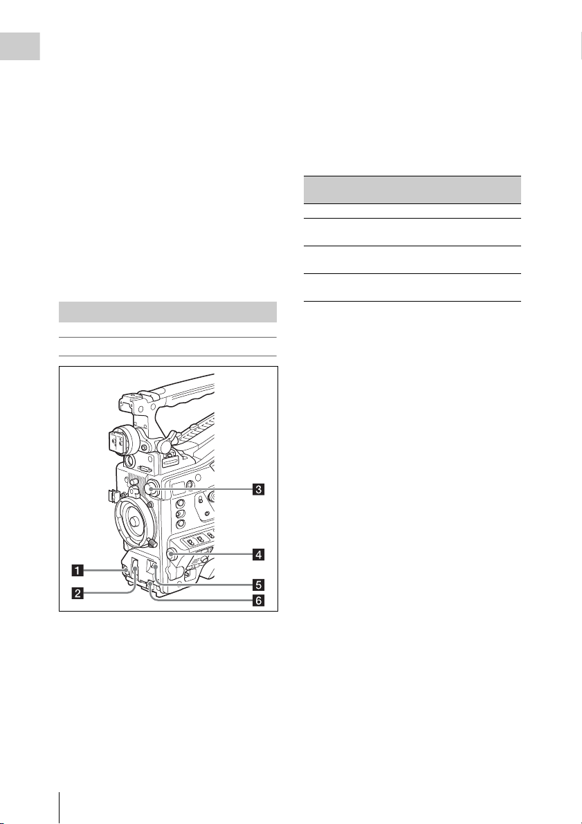
Locations and Functions of Parts and Controls
c DC IN (DC power input) connector
(XLR type, 4-pin, male)
To operate the camcorder from an AC power
supply, connect a n optional DC power cord to this
terminal and then connect the cord to the DC
output terminal of the BC-L70, BC-L160, or
another battery charger.
Power Supply
Adaptor connector (see page 14
a LIGHT switch
Determines how a video light connected to the
LIGHT connector (see page 15) is turned on and
off.
AUTO : When the POWER switch of the video
light is in the on position, the video light is
turned on automatically while the camcorder
is recording.
MANUAL: You can turn the video light on or off
manually, using its own switch.
Note
When the camcorder is set for recording in Picture Cache
mode, it is not possible to turn on the light before
operation to start recording is carried out (or while data
is being stored in memory).
d DC OUT 12V (DC power output)
connector (4-pin, female)
Supplies power for an optional WRR-860C/861/
862 UHF Synthesized Diversity Tuner
(maximum 0.5 A).
Note
Do not connect any equipment other than the UHF
synthesized diversity tuner.
e Battery attachment shoe
Attach a BP-GL95/GL65/L80S/L60S Battery
Pack. Alternatively, you can attach an ACDN2B/DN10 AC Adaptor to operate the
camcorder on AC power supply.
For details, see “Preparing a Power Supply”
(page 34).
For details, see “Attaching a UHF Portable Tuner
(for a UHF Wireless Microphone System)”
(page 44).
Note
For your safety, and to ensure proper operation of the
camcorder, Sony recommends the use of the following
battery packs: BP-GL95, BP-GL65, BP-L60S, and
BP-L80S.
Adaptor connector
Enables connection of an XDCA-55 HD Camera
Adaptor or an HDCA-702 MPEG TS Adaptor. To
connect an adaptor, remove the cover from the
connector and install the optional CBK-HD02
SDI/COMPOSITE Input and 50 Pin Interface.
b POWER switch
Turns the main power supply on and off.
Locations and Functions of Parts and Controls
14
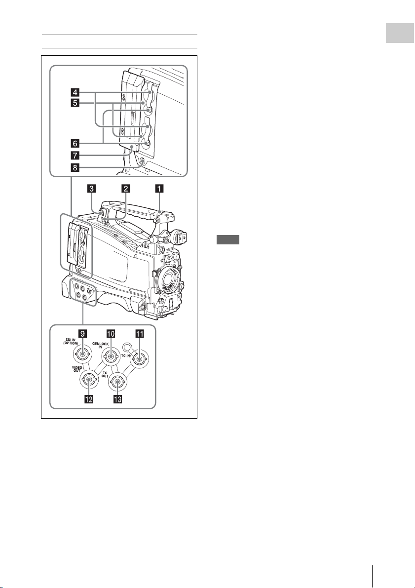
Accessory Attachments
a Shoulder strap fitting
Attach the supplied shoulder strap (see page 48).
b Accessory fitting shoe
Attach an optional accessory such as a video light
(see page 47).
c Viewfinder front-to-back positioning
lever
To adjust the viewfinder position in the front-toback direction, loosen this lever and the LOCK
knob. After adjustment, retighten this lever and
the LOCK knob.
d Viewfinder left-to-right positioning ring
Loosen this ring to adjust the left-to-right position
of the viewfinder (see page 36).
e Viewfinder fitting shoe
Attach the viewfinder.
f VF (viewfinder) connectors (26-pin,
rectangular and 20-pin, round)
The analog interface connector (20-pin) is for
connection of an HDVF series viewfinder, and
the digital interface connector (26-pin) is for
connection of an HD viewfinder CBK-VF01.
Use a connection cable to connect your
viewfinder to the corresponding connector.
Note
Do not connect viewfinders to both connectors at the
same time.
g Lens mount securing rubber
After locking the lens in position using the lens
locking lever, fit this rubber over the lower of the
two projections. This fixes the lens mount,
preventing it from coming loose.
h Viewfinder front-to-back positioning
knob (LOCK knob)
Loosen this knob to adjust the front-to-back
position of the viewfinder (see page 36).
i Fitting for optional microphone holder
Fit an optional CAC-12 Microphone Holder (see
page 43).
j Shoulder pad
Raise the shoulder pad fixing lever to adjust the
position in the front-to-rear direction. Adjust the
position for maximum convenience when
operating the camcorder on your shoulder (see
page 49).
k LIGHT (video light) connector (2-pin,
female)
A video light with a maximum power
consumption of 50 W, such as the Anton Bauer
Ultralight 2 or equivalent can be connected (see
page 47).
l Lens cable clamp
Clamp a lens cable.
m MIC IN (microphone input) (+48 V)
connector (XLR type, 5-pin, female)
Connect a stereo microphone to this connector.
The power (+48 V) is supplied via this connector.
n LENS connector (12-pin)
Connect a lens cable to this connector.
Note
When connecting or disconnecting the lens cable to this
connector, power off the camcorder first.
o Tripod mount
When using the camcorder on a tripod, attach the
tripod adaptor (optional).
Chapter 1 Overview
Locations and Functions of Parts and Controls
15
p Lens mount (special bayonet mount)
Attach the lens.
Chapter 1 Overview
Consult a Sony service representative for
information about available lenses.
q Lens locking lever
After inserting the lens in the lens mount, rotate
the lens mount ring with this lever to lock the lens
in position.
After locking the lens, be sure to use the lens
mount securing rubber to prevent the lens from
becoming detached.
r Lens mount cap
Remove by pushing up the lens locking lever.
When no lens is mounted, keep this cap fitted for
protection from dust.
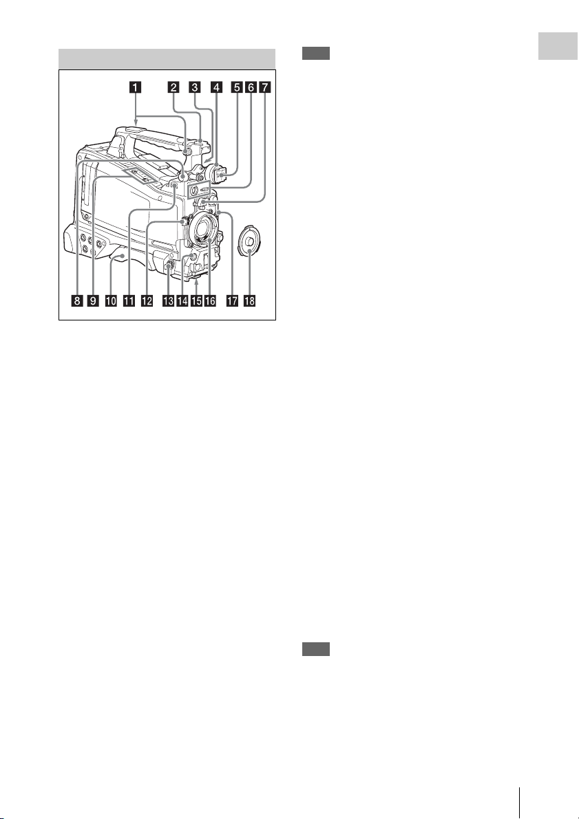
Operating and Connectors Section
Front
For details, see “Setting the Electronic Shutter”
(page 56).
c FILTER selector
Switches between four ND filters built into this
camcorder.
When this selector is used, the new setting
appears on the viewfinder screen for about three
seconds.
FILTER selector
setting
1CLEAR
2
3
4
ND filter
1
/4 ND (attenuates light to
approximately
1
/16 ND (attenuates light to
approximately
1
/64 ND (attenuates light to
approximately
1
/4)
1
/16)
1
/64)
You can change a MAINTENANCE menu
setting so that different white balance settings can
be stored for different FILTER selector positions.
This allows you to automatically obtain optimum
white balance for the current shooting conditions
in linkage with the filter selection.
For details, see “Adjusting the White Balance”
(page 54).
d MENU knob
Changes the item selection or a setting within the
menu (see page 108).
a REC START (recording start) button
Press to start recording. Press it again to stop
recording. The effect is the same as that of the
REC button on the lens.
b SHUTTER selector
Set to ON to use the electronic shutter. Push to
SELECT to switch the shutter speed or shutter
mode setting. When this switch is operated, the
new setting appears on the viewfinder screen for
about three seconds.
Locations and Functions of Parts and Controls
16
e AUTO W/B BAL (automatic white/
black balance adjustment) switch
Activates the automatic white/black balance
adjustment functions.
WHITE: Adjust the white balance automatically.
If the WHITE BAL switch (see page 18) is
set to A or B, the white balance setting is
stored in the corresponding memory. If the
WHITE BAL switch is set to PRST, the
automatic white balance adjustment function
does not operate.
BLACK: Adjust the black set and black balance
automatically.
You can use the AUTO W/B BAL switch even
when the ATW (Auto Tracing White Balance)
function is operating.
If you push the switch to the WHITE side once
more during the automatic white balance
adjustment, the adjustment is cancelled and the
white balance setting returns to the original
setting.
If you push the switch to the BLACK side once
more during the automatic black balance
adjustment, the adjustment is cancelled and the
black balance setting returns to the original
setting.
f MIC (microphone) LEVEL control
Adjusts the input level of audio channels 1, 2, 3
and 4 (see page 59).
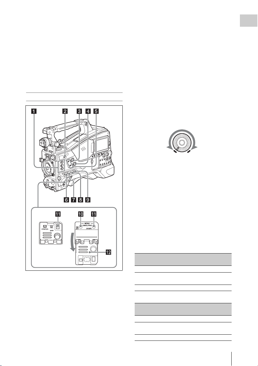
Right side (near the front)
b COLOR TEMP. (color temperature)
button
Press to light the button and change the color
temperature for shooting (factory default setting).
You can use this as an assignable switch (see
page 154).
c ALARM (alarm tone volume
adjustment) knob
Controls the volume of the warning tone that is
output via the built-in speaker or optional
earphones. When the knob is turned to the
minimum position, no sound can be heard.
However, if MAINTENANCE >Audio >Min
Alarm Volume in the setup menu is set to [Set],
the alarm tone is audible even when this volume
control is at the minimum position.
ALARM
Minimum Maximum
d MONITOR (monitor volume
adjustment) knob
Controls the volume of the sound other than the
warning tone that is output via the built-in speaker
or earphones. When the knob is turned to the
minimum position, no sound can be heard.
Chapter 1 Overview
a ASSIGN. (assignable) 1/2/3 switches
You can assign the desired functions to these
switches on OPERATION >Assignable SW in
the setup menu (see page 154).
Off is assigned to the ASSIGN 1/2/3 switches as
the factory default setting.
The ASSIGN.1/3 switches are provided with an
indicator to show whether a function is assigned
to the switch (ON) or not (OFF).
e MONITOR (audio monitor selection)
switches
By means of combinations of the two switches,
you can select audio that you want to hear through
the built-in speaker or earphones.
Position of down-side switch: CH-1/2
Position of up-side
switch
CH-1/CH-3 Channel 1 audio
MIX Channels 1 and 2 mixed
CH-2/CH-4 Channel 2 audio
Audio outp ut
audio (stereo)
a)
Position of down-side switch: CH-3/4
Position of up-side
switch
CH-1/CH-3 Channel 3 audio
MIX Channels 3 and 4 mixed
CH-2/CH-4 Channel 4 audio
Locations and Functions of Parts and Controls
Audio outp ut
audio (stereo)
a)
17

a) By connecting stereo headphones to the EARPHONE
jack, you can hear the audio in stereo. (Under
Chapter 1 Overview
MAINTENANCE >Audio in the setup menu,
Headphone Out must be set to STEREO.)
f ASSIGN. (assignable) 0 switch
You can assign the desired function to this switch
on OPERATION >Assignable SW in the setup
menu (see page 155).
Off is assigned to this switch when the camcorder
is shipped from the factory.
This is a momentary type switch. Each press of
the switch turns the function assigned to this
switch on or off.
g GAIN selector
Switches the gain of the video amplifier to match
the lighting conditi ons during shooting. The gains
corresponding to the L, M, and H settings can be
selected on OPERATION >Gain Switch in the
setup menu (see page 118). (The factory settings
are L=0 dB, M=6 dB, and H=12 dB.)
When this switch is adjusted, the new setting
appears on the viewfinder screen for about three
seconds.
h OUTPUT/DCC (output signal/dynamic
contrast control) switch
Switches the video signal output from the camera
module, between the following two.
BARS: Output the color bar signal.
CAM: Output the video signal being shot. When
this is selected, you can switch DCC
off.
1) DCC (Dynamic Contrast Control): Against a very
bright background with the iris opening adjusted to the
subject, objects in the background will be lost in the
glare. The DCC function will suppress the high
intensity and restore much of the lost detail and is
particularly effective in the following cases.
• Shooting people in the shade on a sunny day
• Shooting a subject indoors, against a background
through a window
• Any high contrast scene
i WHITE BAL (white balance memory)
switch
Controls adjustment of the white balance.
PRST: Adjust the color temperature to the preset
value (the factory default setting: 3200K).
Use this setting when you have no time to
adjust the white balance.
A or B: Recall the white balance adjustment
settings already stored in A or B. Push the
1)
on and
AUTO W/B BAL switch (see page 16) on
the WHITE side, to automatically adjust the
white balance, and save the adjustment
settings in memory A or memory B.
1)
B (ATW
): When this switch is set to B and
OPERATION >White Setting >White
Switch<B> is set to [ATW] in the setup
menu, ATW is activated.
You can use the AUTO W/B BAL switch
even when ATW is in use.
When this switch is adjusted, the new setting
appears on the viewfinder screen for about three
seconds.
1) ATW (Auto Tracing White Balance): The white
balance of the picture being shot is adjusted
automatically for varying lighting conditions.
j MENU ON/OFF switch
To use this switch, open the cover.
This switch is used to display the menu on the
viewfinder screen or the test signal screen. Each
time the switch is pushed down, the menu screen
is turned on and off.
The function of this switch is the same as that of
the MENU button in the thumbnail screen
operations section.
Note
This switch has different functions depending on
whether or not a menu is displayed.
k MENU CANCEL/PRST (preset) /
ESCAPE switch
To use the MENU CANCEL/PRST/ESCAPE
switch, open the cover.
Note
It is not possible to turn off the menu screen by closing
the cover.
Use the switch in the following way when the
menu is not displayed.
CANCEL/PRST: Each time this switch is
pushed upward, a window to confirm the
menu settings and status of the camcorder
appears on the viewfinder screen (see
page 65). The window consists of five pages,
which are switched each time the switch is
pushed upward. Each page is displayed for
about 10 seconds.
ESCAPE: To clear the page immediately after
display, push this switch down to the OFF
position.
Locations and Functions of Parts and Controls
18
Use the switch in the following way when the
menu is displayed.
CANCEL/PRST: Pushing this switch up to this
position after a setting is changed in the setup
menu displays the message to confirm
whether the previous settings are cancelled.
Pushing this switch up to this position again
cancels the previous settings.
Pushing this switch up to this position before
a setting is changed in the setup menu or after
a setting change is cancelled in the setup
menu displays the message to confirm
whether the setting is reset to the initial
value.
Pushing this switch up to this position again
resets the settings to the initial value.
ESCAPE: Use this switch when the menu page,
which has a hierarchical structure, is opened.
Each time the switch is pushed to this
position, the page returns to one stage higher
in the hierarchy.
l Cover
Open this cover to use the MENU ON/OFF
switch or the MENU CANCEL/PRST/ESCAPE
switch.
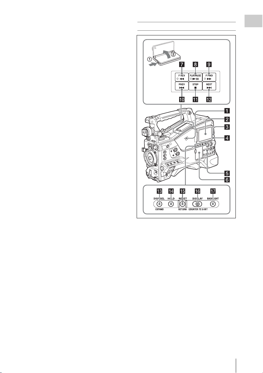
Right side (near the rear)
Chapter 1 Overview
a Built-in speaker
The speaker can be used to monitor E-E1) sound
during recording, and playback sound during
playback. The speaker also sounds alarms to
reinforce visual warnings (see page 175).
If you connect earphones to the EARPHONE
jack, the speaker output is suppressed
automatically.
1) E-E: Abbreviation of “Electric-to-Electric”. In E-E
mode, video and audio signals input to the camcorder
are output after passing through internal electric
circuits only. This can be used to check input signals.
b LCD monitor
Displays remaining battery capacity, remaining
media capacity, audio levels, time data, and so on
(see page 25).
Also allows you to check camera and playback
pictures.
Locations and Functions of Parts and Controls
19

You can adjust the position and angle of the LCD
monitor.
Chapter 1 Overview
c WARNING indicator
Lights up or flashes when an abnormality occurs
(see page 175).
d ACCESS lamp
Lights up in blue when data is written to or read
from the recording media.
i F FWD (fast forward) button and
indicator
This plays back at high speed in the forward
direction. The playback speed changes in the
order ×4 t ×15 t ×24 with each press of the
button. The indicator lights during high-speed
playback in the forward direction.
j PREV button
This jumps to the first frame of the current clip.
If you press this together with the F REV button,
the jump is to the first frame of the first recorded
clip on the recording media.
If you press this button twice in rapid succession,
the jump is to the first frame of the last preceding
clip (or the first frame of the current clip when no
preceding clips exist).
k STOP button
Press this button to stop playback.
e Protection cover of the audio control
section
Open to access the audio control section (see
page 21).
f Protection cover of the thumbnail
screen operations section
Open to access the thumbnail screen operations
section (see page 21).
g F REV (fast reverse) button and
indicator
This plays back at high speed in the reverse
direction. The playback speed changes in the
order ×4 t ×15 t ×24 with each press of the
button. The indicator lights during high-speed
playback in the reverse direction.
h PLAY/PAUSE button and indicator
Press this button to view play back video images
using the viewfinder screen or the LCD monitor.
The indicator lights during playback.
Press this button again during playback to pause,
outputting a still image. At this time the indicator
flashes at a rate of once per second.
Pressing the F REV or F FWD button during
playback or pause starts high speed playback in
the forward or reverse direction.
l NEXT button
This jumps to the first frame of the next clip.
If you press this together with the F FWD button,
the jump is to the first frame of the last recorded
clip on the recording media.
m DISP SEL (display selection)/EXPAND
(expand function) button
With each press of this button, the display in the
LCD monitor changes as follows.
Display indication Meaning
Video with
superimposed
information (CHAR)
Video without
superimposed
information (MONI)
Status display
(STATUS)
If you press this button when the thumbnail
screen is displayed, the duration of the selected
clip is divided into fractions, and the first frame of
each of the divisions is shown in a further
thumbnail display (expand function). For an HD
recorded MP4 clip, its duration is divided into 12.
If an SD recorded AVI clip comprises multiple
files, the divisions are displayed for the individual
files.
The LCD monitor displays
the same text information as
the viewfinder.
The video only appears.
Counter indications,
warnings, audio levels, and
similar information appear.
No video image appears.
Locations and Functions of Parts and Controls
20
For MP4 clips, each time you press this button the
division is repeated. Hold down the SHIFT button
and press this button to step back through the
division process.
n HOLD (display hold) button
Pressing this button instantly freezes the time data
displayed in the LCD monitor. (The timecode
generator continues runni ng.) Pressing this button
again releases the hold.
For details of the counter display, see page 26.
o RESET/RETURN button
Resets the value shown in the time counter
display in the LCD monitor. According to the
settings of the PRESET/REGEN/CLOCK switch
(see page 22) and the F-RUN/SET/R-RUN
switch (see page 22), this button resets the
display as follows.
Settings of switches To r e s e t
DISPLAY switch: COUNTER Counter to
DISPLAY switch: TC
PRESET/REGEN/CLOCK
switch: PRESET
F-RUN/SET/R-RUN switch:
SET
DISPLAY switch: U-BIT
PRESET/REGEN/CLOCK
switch: PRESET
F-RUN/SET/R-RUN switch:
SET
a) Of the timecode bits for every frame recorded on the
media, those bits which can be used to record useful
information for the user such as scene number,
shooting place, etc.
For details, see “Setting the Time Data” (page 61).
0:00:00:00
Timecode to
00:00:00:00
User bits data
00 00 00 00
a)
to
This button returns to the previous screen when
pressed during thumbnail screen display, expand
thumbnail screen display, or essence mark
thumbnail screen display.
p DISPLAY switch
This cycles the data displayed in the time counter
display in the LCD monitor through the sequence
COUNTER, TC, and U-BIT (see page 26).
COUNTER: Display the elapsed recording/
playback time (hours, minutes, seconds,
frames).
TC: Display timecode.
U-BIT: Display user bits data.
q BRIGHT (brightness) button
Switches the brightness of the LCD monitor
backlight.
Each press of the button selects the next setting in
the order shown in the following table.
If you press the button with the LCD monitor off,
the LCD backlight comes on in the H state.
Setting LCD monitor backlight
H High (select this to view the LCD
monitor outdoors in the daytime)
M Brightness between H and L
L Low (select this to view the LCD monitor
indoors or outdoors at night)
OFF Off (the display is also off)
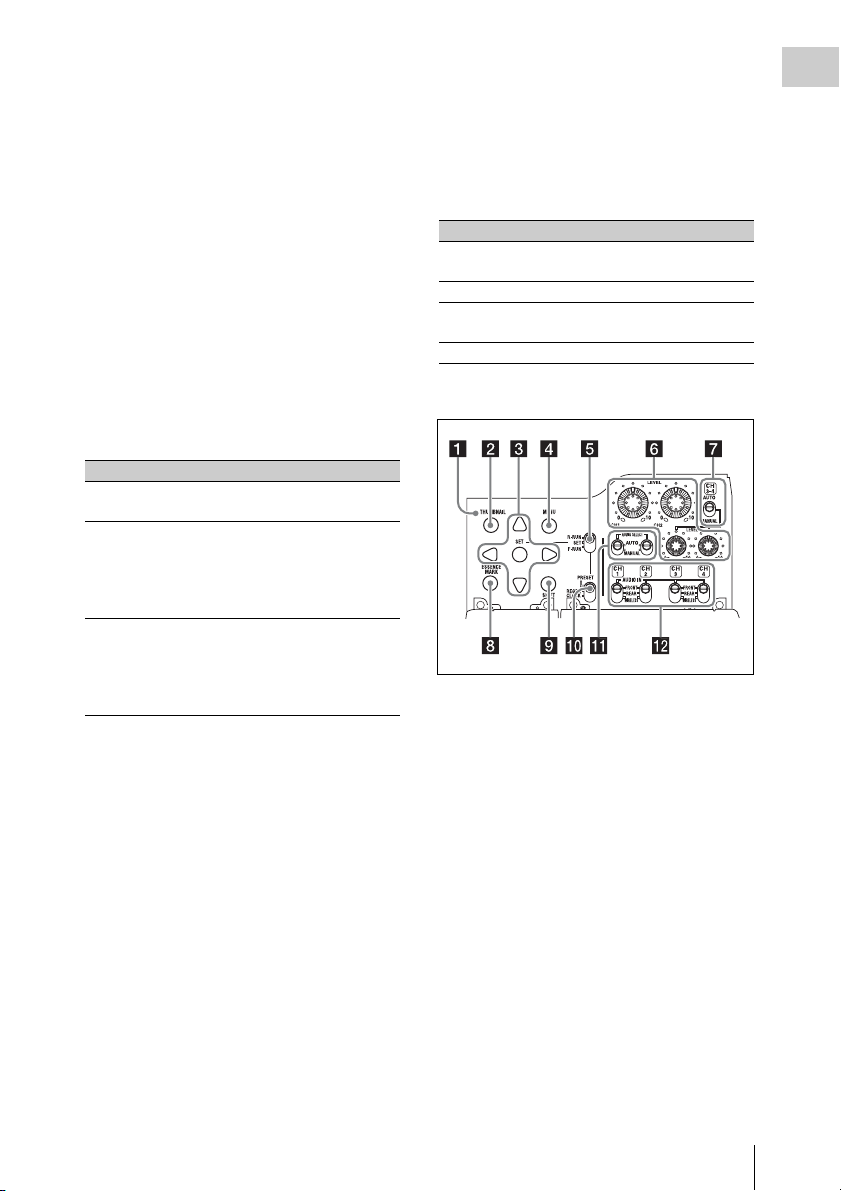
Thumbnail screen operations section and audio
control section
a THUMBNAIL indicator
This lights when thumbnail screen is displayed.
b THUMBNAIL button
Press this button to display the thumbnail screen
(see page 90) and to carry out a thumbnail
operation.
Press once more to return to the original display.
c SET (set) button and arrow buttons
Use these buttons to make timecode and user bit
settings, and for thumbnail screen operations (see
page 97).
When the menu is displayed, press this button to
select an item or to confirm the setting change.
d MENU button
Each press of this button turns the setup menu
display on and off.
The function of this button is the same as that of
the MENU ON/OFF switch.
Chapter 1 Overview
Locations and Functions of Parts and Controls
21

e F-RUN/SET/R-RUN (free run/set/
Chapter 1 Overview
recording run) switch
Selects the operating mode of the internal
timecode generator. The operating mode is set as
explained below, depending on the position of the
switch.
F-RUN: Timecode keeps advancing, regardless
of whether the camcorder is recording. Use
this setting when synch ronizing the timecode
with external timecode.
SET: Sets the timecode or user bits.
R-RUN: Timecode advances only during
recording. Use this setting to have a
consecutive timecode on the recording
media.
For details, see “Setting the Timecode” (page 61)
and “Setting the User Bits” (page 62).
f LEVEL CH1/CH2/CH3/CH4 (audio
channel 1/2/3/4 recording level) knobs
Adjust the audio levels to be recorded on channels
1, 2, 3, and 4 when the AUDIO SELECT CH1/
CH2 and AUDIO SELECT CH 3-4 switches are
set to MANUAL.
g AUDIO SELECT CH 3-4 (audio
channel 3/4 adjustment method
selection) switch
Select the audio level adjustment method for each
of audio channels 3 and 4.
AUTO : Automatic adjustment
MANUAL: Manual adjustment
h ESSENCE MARK button
By pressing this button when a thumbnail display
is on the screen, you can view the following
thumbnail displays of the essence-marked frames
of the selected clip, depending on the item
selected in a list displayed on the screen.
All: Thumbnail display of all frames marked with
essence marks.
Rec Start (in UDF mode): Thumbnail display of
frames marked with Rec Start marks and of
the first frames o f clips (when the first frames
are not marked with Rec Start marks).
Shot Mark1: Thumbnail display of the frames
marked with Shot Mark 1
Shot Mark2: Thumbnail display of the frames
marked with Shot Mark 2
You can also select Shot Mark 0 and Shot Mark 3
to Shot Mark 9.
If you have recorded clips by using planning
metadata that defined names for Shot Mark 0 to
Shot Mark 9, the defined names are displayed
instead of the above item names in the list.
i SHIFT button
Use this in combination with other buttons.
j PRESET/REGEN (regeneration)/
CLOCK switch
Selects the type of timecode to record.
PRESET: Record new timecode on the media.
REGEN: Record timecode continuous with the
existing timecode recorded on the media.
Regardless of the setting of the F-RUN/SET/
R-RUN switch, the camcorder operates in RRUN mode.
CLOCK: Record timecode synchronized to the
internal clock. Regardless of the setting of
the F-RUN/SET/R-RUN switch, the
camcorder operates in F-RUN mode.
k AUDIO SELECT CH1/CH2 (audio
channel 1/2 adjustment method
selection) switches
Select the audio level adjustment method for each
of audio channels 1 and 2.
AUT O: Automatic adjustment
MANUAL: Manual adjustment
l AUDIO IN CH1/CH2/CH3/CH4 (audio
channel 1/2/3/4 input selection) switches
Select the audio input signals to be recorded on
audio channels 1, 2, 3 and 4.
FRONT: Audio input signals from the
microphone connected to the MIC IN
connector
REAR: Audio input signals from an audio device
connected to the AUDIO IN CH-1/CH-2
connectors
WIRELESS: Audio input signals from the UHF
portable tuner if it is installed
Locations and Functions of Parts and Controls
22
Left side and upper section
b PC connector
Used to put this camcorder into USB connection
mode and use it as an external storage device for
a computer. When a computer without
ExpressCard slot is connected to this connector,
every memory card inserted in the camcorder is
recognized as a drive for that computer.
c External device connector
Connect an optional CBK-WA01 Wi-Fi Adapter
or a USB flash drive.
When a CBK-WA01 is connected: Wireless
LAN connection is available.
When a USB flash drive is connected:
Recording, saving and loading the following
data are available.
• Recording of proxy data (see page 84)
• Loading of planning metadata (see
page 86)
• Save and load setting data (see page 159)
Notes
• When you connect a CBK-WA01, install the optional
CBK-UPG01 Hardware Upgrade Key.
• Use this connector only for connecting a CBK-WA01
or a USB flash drive. Do not connect and use a USB
hub or similar products.
For details on how to use t he CBK-WA01, refer to the
Supplement supplied in the CD-ROM (labeled
“Manuals for Solid-State Memory Camcorder”).
Chapter 1 Overview
a ASSIGNABLE 4/5 switches
You can assign the desired functions to these
switches on OPERATION >Assignable SW in
the setup menu (see page 155).
Off is assigned to these switches when the
camcorder is shipped from the factory.
d SxS memory card slots
These two slots (A and B) can receive SxS
memory cards or other recording media (see
page 68).
e ACCESS lamps
Indicate the state of slots A and B (see page 68).
You can check whether the lamps are lit even
when the slot cover is closed.
f EJECT buttons
To remove the recording media from the slot,
press the EJECT button to release the lock, then
press the button once more. This makes the media
come out of the slot partially (see page 69).
g Slot cover
Slide to the left and right to open and close.
Locations and Functions of Parts and Controls
23
h SLOT SELECT (SxS memory card
Chapter 1 Overview
select) button
When SxS memory cards are loaded in both card
slots A and B, press this button to select the card
you want to use (see page 69).
i SDI IN (OPTION) (SDI input
(optional)) connector (BNC type)
When the optional CBK-HD02 SDI/
COMPOSITE Input and 50 Pin Interface is
installed, the camcorder can record HDSDI or
SDSDI signals input to this connector.
j GENLOCK IN (genlock signal input)
connector (BNC type)
This connector inputs a reference signal when the
camcorder is to be gen locked or when timecode is
to be synchronized with external equipment.
Available refer ence signals vary depending on the
current system frequency as shown in the
following table.
System frequency Available reference signals
1080/59.94i 1080/59.94i, 480/59.94i
1080/29.97P 1080/59.94i, 480/59.94i
1080/23.98P (PsF
output)
1080/23.98P
(Pulldown output)
720/59.94P 1080/59.94i, 720/59.94P,
720/29.97P 1080/59.94i, 720/59.94P,
720/23.98P 1080/59.94i, 720/59.94P,
480/59.94i 1080/59.94i, 480/59.94i
480/29.97P 1080/59.94i, 480/59.94i
1080/50i 1080/50i, 576/50i
1080/25P 1080/50i, 576/50i
720/50P 1080/50i, 720/50P, 576/50i
720/25P 1080/50i, 720/50P, 576/50i
576/50i 1080/50i, 576/50i
576/25P 1080/50i, 576/50i
1080/23.98PsF, 480/59.94i
1080/59.94i, 480/59.94i
480/59.94i
480/59.94i
480/59.94i
(Genlock for the camera module supports
horizontal sync signals only.) Use
MAINTENANCE >GENLOCK in the setup
menu to adjust the genlock H-phase (phase of
horizontal sync signal).
When the optional CBK-HD02 SDI/
COMPOSITE Input and 50 Pin Interface is
installed, the camcorder can record analog
composite video signals input to this connector.
k TC IN (timecode input) connector
(BNC type)
To apply an external lock to the timecode of the
camcorder, input the reference timecode.
For details, see “Setting the Timecode” (page 61).
l VIDEO OUT connector (BNC type)
Outputs video signals for monitoring. The output
signals can be selected either composite video or
HD-Y depending on the setting of OPERATION
>Input/Output >Output&i.LINK in the setup
menu.
m TC OUT (timecode output) connector
(BNC type)
To lock the timecode of an external VTR to the
timecode of this camcorder, connect this
connector to the external VTR’s timecode input
connector.
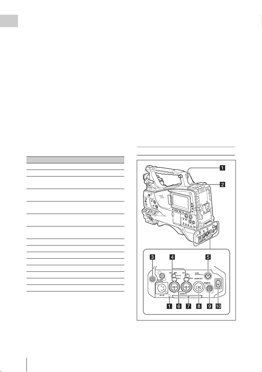
Rear
Locations and Functions of Parts and Controls
24
a TALLY (back tally) indicators (red)
Light up during recording. They will not light if
the TALLY switch is set to OFF. These indicators
also flash to indicate warnings (see page 20). The
tally indicator on the front of the viewfinder and
the REC indication on the viewfinder screen light
or flash in the same manner.
For details, see “Operation Warnings” (page 175).
b TALLY switch
Set to ON to activate the TALLY indicator
function.
c EARPHONE jack (stereo, minijack)
You can monitor the E-E sound during recording
and playback sound during playback. When an
alarm is indicated, you can hear the alarm sound
through the earphone. Plugging an earphone into
the jack automatically cuts off the built-in
speaker.
You can select monaural or stereo on
MAINTENANCE >Audio in the setup menu.
d AUDIO IN selectors
Select the audio source you connect to the
AUDIO IN CH1/CH2 connectors.
LINE: When connecting a stereo amplifier or
other external audio signal source
MIC: When connecting a microphone that does
not require 48 V power supply
+48V: When connecting a microphone that
requires 48 V power supply
e HD/SD SDI OUT connector (BNC type)
Outputs an HDSDI or SDSDI signal (with
embedded audio). The output from this connector
can be turned on or off by OPERATION >Input/
Output >SDI Output in the setup menu.
By loosening the screws which retain the cover to
the bottom of the camcorder, you can adjust the
position of the cover depending on the size and
shape of the microphone or audio cable plugs.
After adjusting the position, tighten the screws to
secure the cover.
h AUDIO OUT connector (XLR type, 5-
pin, male)
Outputs the audio signals recorded on audio
channels 1 and 2 or audio channels 3 and 4. The
audio signals are selected by the MONITOR
switch.
i REMOTE connector (8-pin)
Connect a remote control unit, which makes it
possible to control the camcorder remotely.
Note
Before connecting/disconnecting the Remote Control
Unit to/from the camcorder, be sure to turn off the
camcorder POWER switch.
j i.LINK (HDV/DV) connector (6-pin,
IEEE1394 compliant, S400)
FAT
When the recording mode is FAT, to input and
output HDV/DV streams, connect to an HDV/DV
device.
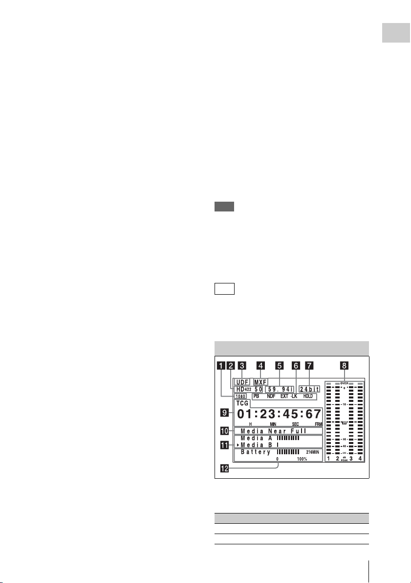
LCD Monitor
Chapter 1 Overview
f AUDIO IN CH-1/CH-2 (audio channel
1 and channel 2 input) connectors (XLR
type, 3-pin, female)
These are audio input connectors for channels 1
and 2 to which you can connect audio equipment
or a microphone.
g Bottom cover
This is provided for protecting the cables
connected to the connectors on the rear panel.
a Resolution
Indicates the resolution of HD output video.
Indication Resolution (horizontal × vertical)
1080 1080 lines (1920 × 1080)
720 720 lines (1280 × 720)
Locations and Functions of Parts and Controls
25

b Recording format
Indicates the current recording format or the
Chapter 1 Overview
recording format of clip being currently played.
•UDF mode
HD422 50
HD420 HQ
IMX50
DVCAM
• FAT mode
HQ1920
HQ1440
HQ1280
SP1440
DVCAM
c Recording mode
UDF: UDF mode
FAT: FAT mode
d File format
MXF: When the recording mode is UDF
MP4: When the recording mode is FAT-HD
mode
DV-AVI : When the recording mode is FAT-SD
mode
e System frequency
Indicates the system frequency of video being
currently played or recorded.
59.94i
29.97P
23.98P
50i
25P
59.94P
50P
Indication Status
Recording
mode
16bit FAT Any format
UDF • HD420 HQ
24bit UDF • HD422 50
Recording format
•DVCAM
• IMX (Audio Length is
set to16 bit)
• IMX (Audio Length is
set to24 bit)
h Audio level indicators
Indicate the audio recording or play levels of
channels 1 to 4.
i Time counter display
Switches displays of time counter values,
timecode, and user bits data, depending on the
position of the DISPLAY switch.
Displays the type of data currently shown in the
time counter, as follows.
TCG: Recorded timecode
TCR: Playback timecode
UBG: Recorded user bits
UBR: Playback user bits
CNT: Counter
CLK: Time display (when the PRESET/REGEN/
CLOCK switch is set to CLOCK)
When the HOLD button is pressed to hold the
timecode value, the timecode is displayed in the
format shown below. When the HOLD button is
pressed again to release the hold, the timecode is
displayed in the normal format.
f Status display
PB: Appears during play.
NDF: Appears when non-drop-frame timecode is
selected.
EXT-LK: Appears when the internal timecode
generator is locked to an external signal input
to the TC IN (timecode input) connector.
HOLD: Appears when the operation mode of the
internal timecode generator is set to R-RUN
and stopped.
g Audio format
Indicates the audio recording format or the audio
format of clip being currently played.
Locations and Functions of Parts and Controls
26
The three dots indicates that timecode is
displayed in the hold mode.
j Warning indicator area
Displays warnings when trouble with recording
or moisture condensation occurs.
For details, see “Operation Warnings” on page 175.
You can also display the name of the next clip to
be recorded (see page 126).
k Remaining media capacity indicator
Shows bar segments indicating the remaining
capacity of recording media in the slots.
l Remaining battery capacity indicator
Shows bar segments indicating the remaining
battery capacity.
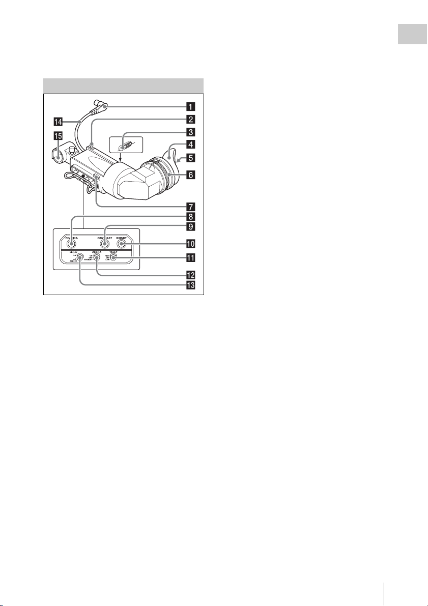
HDVF-20A Viewfinder (Optional)
g Tally indicator
Lights up while camcorder is recording. Set the
TALLY switch to OFF when not in use. The
brightness can also be adjusted with the TALLY
switch.
This indica tor also flashes to indi cate warnings, in
the same manner as the camera operator tally
indicator and the recording/red tally indicators in
the viewfinder.
h PEAKING control
Turning this control clockwise adjusts the picture
sharpness, and makes focusing easier. This
control has no effect on the output signals of the
camcorder.
i CONTRAST control
Adjusts the contrast of the screen. This control
has no effect on the output signals of the
camcorder.
j BRIGHT control
Adjusts the brightness of the screen. This control
has no effect on the output signals of the
camcorder.
Chapter 1 Overview
a Plug
Connect to the VF connector (20-pin) on the
camcorder.
b Stopper
Prevents the viewfinder from coming off the
camcorder when it is slid from side to side.
c Camera operator tally indicator
Lights up while camcorder is recording. This
indicator can be covered when not in use.
This indicator also flashes to indicate warnings, in
the same manner as the tally indicator and the
recording/red tally indicators in the viewfinder.
d Eyecup
e Indicators and status display
For details, see “Status Display on the Viewfinder
Screen” on page 29.
f Diopter adjustment ring
Allows for optimal focus adjustment.
k TALLY switch
Controls the tally indicator located on the front of
the viewfinder.
HIGH: The tally indicator brightness is set to
high.
OFF: The tally indicator is disabled.
LOW: The tally indicator brightness is set to low.
l ZEBRA (zebra pattern) switch
Controls the zebra pattern display on the
viewfinder screen as follows.
ON: A zebra pattern appears and stays.
OFF: The zebra pattern disappears.
MOMENT: A zebra pattern appears and stays for
about five seconds.
m DISPLAY/ASPECT switch
Turns the marker indication on and off, and
switches between 4:3 and 16:9 aspect ratios for
viewfinder screen display.
DISPLAY: When the marker indication is
enabled with the camcorder, the marker
indication on the viewfinder screen turns on
and off every time you push the switch up to
this position.
ASPECT: Each push of the switch down to this
position toggles the mask display on and off.
Locations and Functions of Parts and Controls
27
(Make mask display settings using
Chapter 1 Overview
OPERATION >Marker >Aspect Mask in the
setup menu (see page 118).)
n Viewfinder cable
o Microphone holder
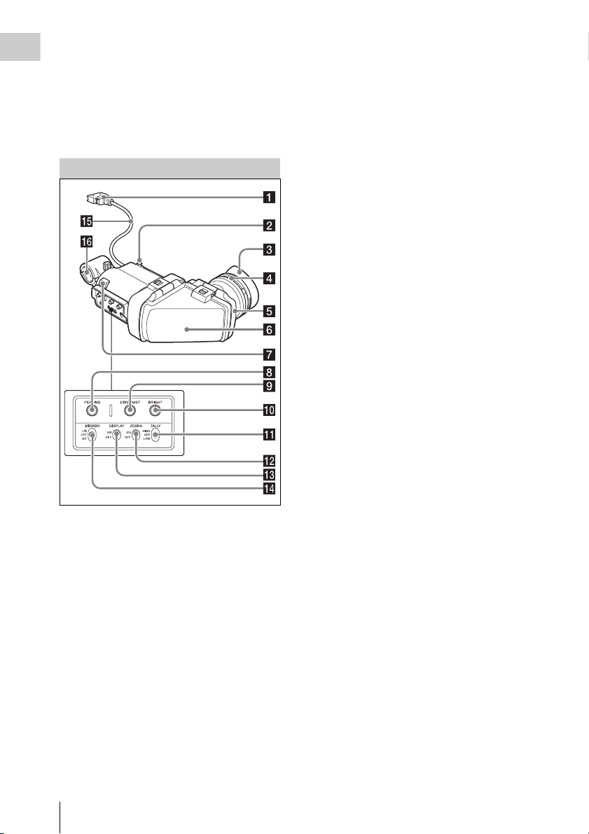
CBK-VF01 Viewfinder (Optional)
a Plug
Connect to the VF connector (26-pin) on the
camcorder.
b Stopper
Prevents the viewfinder from coming off the
camcorder when it is slid from side to side.
c Eyecup
d Diopter adjustment ring
Allows for optimal focus adjustment.
e Eyepiece
You can raise this up when required by the
situation.
f Viewfinder barrel
You can raise this up or rotate when required by
the situation.
g Tally indicator
Lights up when recording is started by a press of
the REC START button on this camcorder, the
VTR button on the lens, or the VTR button on the
remote control unit.
When an abnormality occurs, the tally indicator
flashes to indicate a warning.
h PEAKING control
Turning this control clockwise adjusts the picture
sharpness, and makes focusing easier. This
control has no effect on the output signals of the
camcorder.
i CONTRAST control
Adjusts the contrast of the screen. This control
has no effect on the output signals of the
camcorder.
j BRIGHT control
Adjusts the brightness of the screen. This control
has no effect on the output signals of the
camcorder.
k TALLY switch
Controls the tally indicator located on the front of
the viewfinder.
HIGH: The tally indicator brightness is set to
high.
OFF: The tally indicator is disabled.
LOW: The tally indicator brightness is set to low.
l ZEBRA (zebra pattern) switch
Controls the zebra pattern display on the
viewfinder screen as follows.
ON: Display a zebra pattern.
OFF: Do not display a zebra pattern.
m DISPLAY switch
Turns the display of text information on and off.
ON: Display text information.
OFF: Do not display text information.
n MIRROR switch
The image display on the monitor screen becomes
reversed horizontally or vertically when the
viewfinder barrel is raised up or rotated. Use this
switch to control the image display in such
situation.
Locations and Functions of Parts and Controls
28
L/R: Reverse the image horizontally.
OFF: Do not reverse the image.
B/T: Reverse the image vertically.
o Viewfinder cable
p Microphone holder
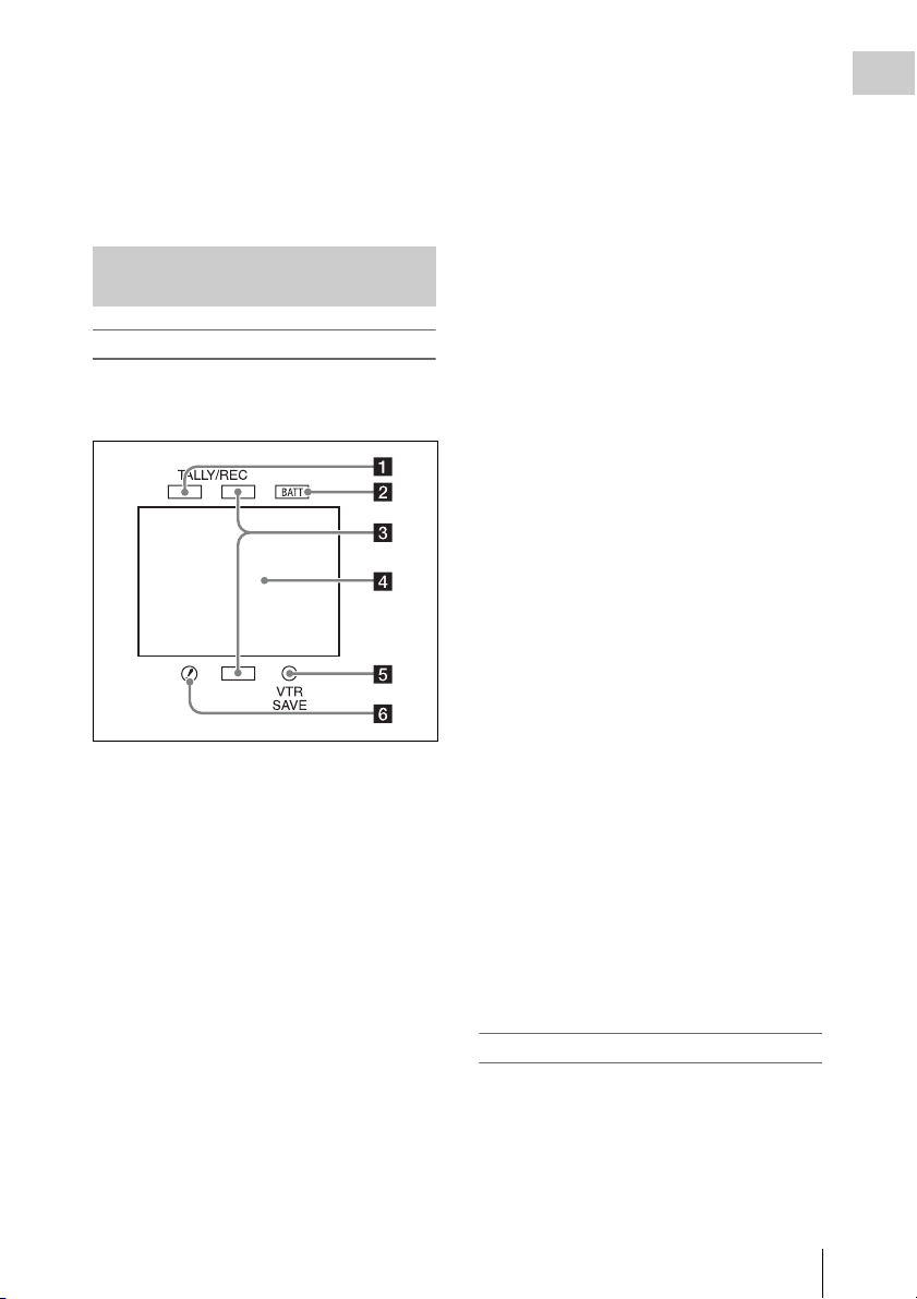
Status Display on the Viewfinder Screen
Indicators (HDVF-20A)
The following indicators are arranged above and
below the screen of the HDVF-20A to show the
current state and adjustments of the camcorder.
b BATT (battery) indicator
This indicator starts flashing when the battery
connected to the camcorder is nearly exhausted,
and stays lit when the battery is completely
exhausted.
To prevent interruption during operation, replace
the battery as soon as this indicator starts flashing.
The battery power level at which the indicator starts
flashing can be set by MAINTENANCE >Battery in
the setup menu. For details, see page 134.
c Recording/red tally indicators
Light when the camcorder is the following states.
• Recording with the MAINTENANCE >Camera
Config >HD/SDI Remote I/F menu item set to
[R-Tally]
• Green tally signal or call signal received (when
a camera adaptor is mounted on the camcorder
and a camera extension unit is connected)
These indicators also flash to indicate warnings,
in the same manner as the tally indicator and the
camera operator tally indicator.
d Viewfinder screen
See “Viewfinder screen display” (page 29).
e VTR SAVE indicator
Do not function on this camcorder.
Chapter 1 Overview
a Green tally indicator
Lights when the camcorder is the following
states.
• Picture Cache mode enabled
• Green tally signal received (when a camera
adaptor is mounted on the camcorder and a
camera extension unit is connected)
• Recording with MAINTENANCE >Camera
Config >HD/SDI Remote I/F in the setup menu
set to [G-Tally]
Flashes when the camcorder is the following
states.
• Set to Interval Rec mode or the consecutive
mode of Frame Rec mode (1 flash per second)
• Recording in Interval Rec mode or recording in
the consecutive mode of Frame Rec mode (4
flashes per second)
• Set to the single-shot mode of Frame Rec mode,
or recording in that mode (2 flashes per second)
f ! (warning) indicator
This indicator lights when any of the following
conditions occurs with the corresponding item set
to [On] by OPERATION >“!” LED in the setup
menu.
• The gain is set to other than 0 dB.
• The SHUTTER selector is set to ON.
• The WHITE BAL switch is set to PRST.
• ATW is enabled.
• The lens extender is used.
• The reference value of auto iris adjustment is
not the standard value.
• The FILTER selector is set to other than 1.
Viewfinder screen display
The viewfinder screen displays not only the video
picture but also characters and messages
indicating the camcorder settings and operating
status, a center marker, a safety zone marker, etc.
When the menu screen is not displayed and the
DISPLAY switch is set to ON, the items for
which an ON setting was made with
Locations and Functions of Parts and Controls
29
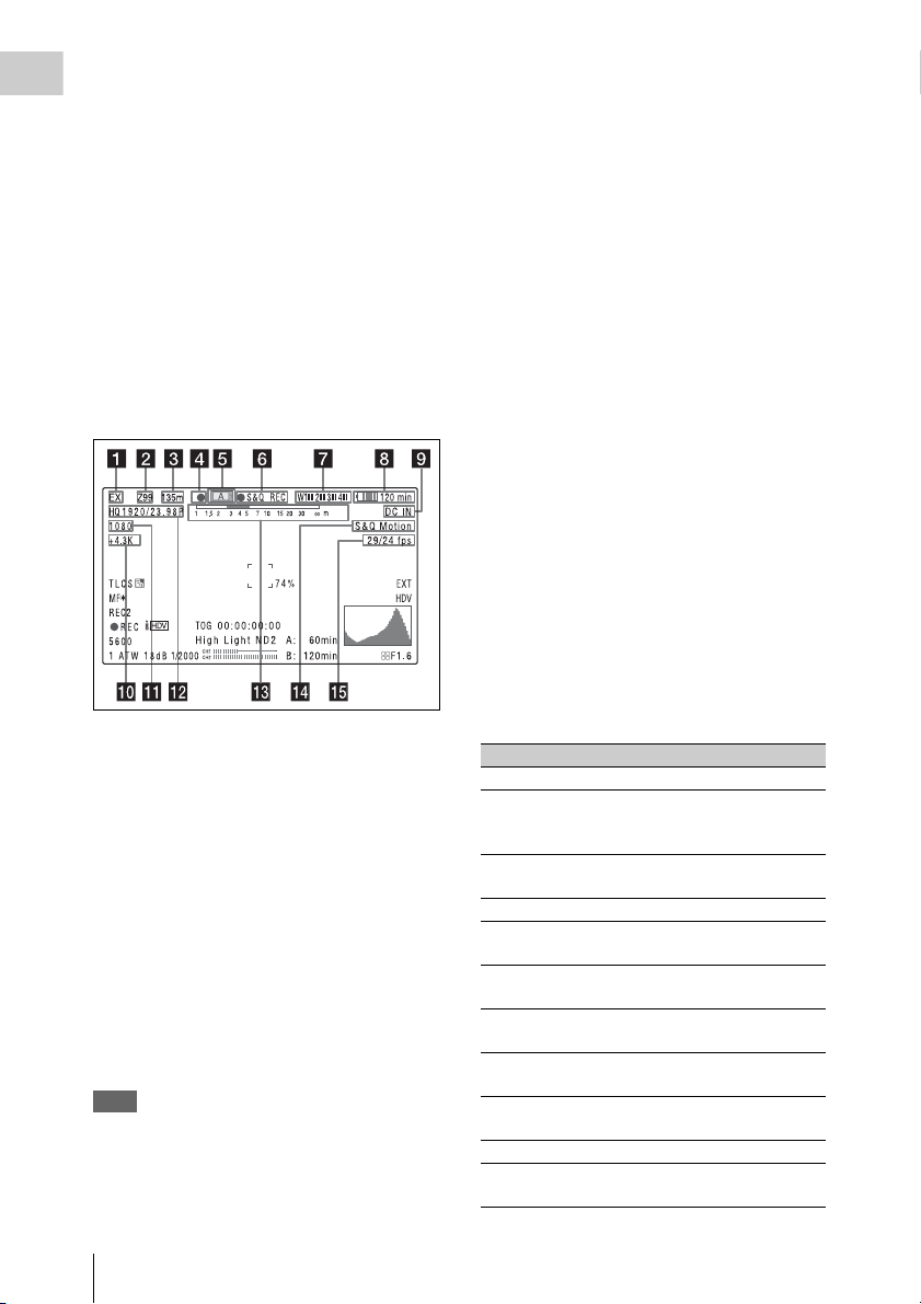
OPERATION >Super Impose in the setup menu
or with related switches are displayed at the top
Chapter 1 Overview
and bottom of the screen.
Caution messages are indicated for three seconds
when you carry out operations to change
camcorder settings. Adjustment execution
messages are indicated while adjustments
proceed. When adjustments are finished,
messages showing the results of adjustments
appear for three seconds.
Not only these indications are displayed on the
viewfinder screen, but a menu setting enables
them to be output as video signals.
All items that can be displayed on the viewfinder
screen are shown below.
Top of viewfinder screen
a Extender settings
Indicates the setting of the digital extender
function (when optional CBK-HD02 SDI/
COMPOSITE Input and 50 Pin Interface is
installed) of this camcorder and the setting of the
lens extender.
EX: The lens extender is on.
08: The lens shrinker is on.
x2D: The digital extender function of this
camcorder is on.
Ex2D: The lens extender and the digital extender
function of this camcorder are both on.
Digital extender function can be turned on or off
by an assignable sw itch to which Digi tal Extender
is assigned.
Note
When slow & Quick motion is selected or the freeze mix
function is used, the digital extender cannot be turned on.
When the camcorder is in focus magnification (Focus
Mag) mode, turning on the digital extender cancels the
mode.
b Zoom position (when the lens is
mounted)
Indicates the zoom position of the zoom lens in
the range from 0 to 99.
c Focus position (when the serial lens is
mounted)
Indicates the focus position as distance to the
subject (in units of m).
d Green tally
Lights when the camcorder is the following
states.
• MAINTENANCE >Camera Config >HD-SDI
Remote I/F is set to [G-Tally] in the setup menu
and a recording control signal is output from the
HD/SD SDI OUT connector.
• When the Picture Cache mode is enabled
• Green tally signal received (when a camera
adaptor is mounted on the camcorder and a
camera extension unit is connected)
e Media status
Displays the name of the currently active media
slot (A or B).
f Special recording mode/operation
status
Indicates the current special recording mode/
operation status as follows.
Indication Meaning
zREC Recording in progress
STBY When recording is on a break in
CONT Standby for next recording in Clip
zCACHE Standby in Picture Cache mode
zINT REC Recording in progress in Interval
zINT STBY Standby for next recording in
INT STBY Standby in Interval Recording
zFRM REC Recording in progress in Frame
zFRM
STBY
FRM STBY Standby in Frame Recording mode
zS&Q REC Recording in progress in Slow &
Clip Continuous Rec mode or
standby in other modes
Continuous Rec mode
Recording mode
Interval Recording mode
mode
Recording mode
Standby for next recording in
Frame Recording mode
Quick Motion mode
Locations and Functions of Parts and Controls
30
 Loading...