

Page 1
Digital Video
Camera Module
D-020-100-11 (2)
Technical Manual
XCU-CG160/CG160C
© 2018 Sony Corporation
Page 2

Table of Contents
Overview
Features ...................................................................3
Phenomena Specific to Image Sensors .................4
System Components ...............................................4
Location and Function of Parts and
Operation ................................................................5
Front/top/bottom .................................................5
Rear .....................................................................5
Getting Started
Connections ............................................................6
About the power supply ......................................6
USB 3.0 connection ............................................6
Connecting the cables .........................................7
Mounting on a tripod ..........................................7
When mounting the camera ................................7
Functions
Trigger Signal Input ..............................................8
Trigger signal polarity ........................................8
GPIO Connector ....................................................9
Partial Scan ..........................................................11
Binning (XCU-CG160 only) ................................11
Camera Mode .......................................................12
Multi ROI .............................................................13
Output Format .....................................................14
Image Flip .............................................................15
Gain .......................................................................15
Manual gain ......................................................15
Auto gain (AGC) ..............................................15
Area gain ...........................................................15
Shutter (Exposure) ...............................................16
Configuration method .......................................16
Auto exposure (AE) ..........................................16
Combination of Continuous AGC and
Continuous AE .....................................................16
Trigger Control ....................................................17
Free run/trigger mode .......................................17
Trigger source ...................................................17
Burst trigger ......................................................18
Trigger inhibit ...................................................19
Trigger delay .....................................................20
Trigger counter .................................................20
Trigger range limit ............................................20
Frame Rate ...........................................................21
Auto frame rate .................................................21
Specifying the frame rate ..................................21
Displaying the frame rate ..................................21
Fastest frame rate for partial scanning ..............21
Frame Counter .....................................................22
Timing Chart ....................................................... 22
Trigger latency/Exposure time ......................... 22
Trigger overlap ................................................. 23
White Balance (Color Camera Only) ................ 24
LUT ....................................................................... 25
Binarization ...................................................... 25
5-point interpolation ......................................... 25
Arbitrary setting ............................................... 25
Saving a LUT ................................................... 26
Color Matrix Conversion (Color Camera
Only) ..................................................................... 26
Test Chart Output ............................................... 26
3 × 3 Filter ............................................................ 27
GPIO ..................................................................... 28
GPI ................................................................... 28
GPO .................................................................. 28
Status LED ........................................................... 30
Temperature Readout Function ......................... 30
Defect Correction ................................................. 30
Shading Correction ............................................. 31
User Set .................................................................33
User set memory .............................................. 33
User ID .................................................................. 33
Saving and Startup .............................................. 33
Camera Information ........................................... 33
Restarting ............................................................. 33
Command List ..................................................... 34
Specifications
Specifications ........................................................ 42
Spectral Sensitivity Characteristics (Typical
Values) .................................................................. 43
Dimensions ........................................................... 44
2
Page 3

Overview
This unit is a digital video camera module that adopts a
USB 3.0 interface for image output and camera control.
The XCU-CG160 is a monochrome models, and the
XCU-CG160C is a color model.
In this document, “Digital Video Camera Module” is
referred to as the “unit”, “XCU-CG160” as
“Monochrome camera”, and “XCU-CG160C” as “Color
camera”.
Features
USB 3.0 interface
Image output and camera control are performed over a
USB 3.0 interface.
USB3 Vision adoption
The USB3 Vision standard is adopted to enable simple
camera control.
High image quality
This unit produces stable output images, by adopting the
latest CMOS image sensors with a global shutter
function. By adopting a square pixel image sensor,
images can be processed using the original aspect ratio
without a conversion procedure.
Various settings
Various settings can be configured by sending a
command from a host device.
White balance control (color camera only)
You can adjust the R and B levels relative to the G level
to adjust the white balance. This unit is also equipped
with a one-push white balance function for automatic
camera white balance adjustment.
Area gain function
You can set the gain between 0 to 32 times for up to 16
arbitrary positions. If the set area is duplicated, the lownumbered area takes priority.
Equipped with temperature sensor
The camera’s internal temperature can be read from a
temperature sensor mounted on the module board. If the
update interval of the temperature sensor value is set to
other than 0, temperature information can be sent to a
PC application as event data.
Pixel defect correction function
This unit is equipped with a defective pixel correction
function that reduces the effect of sensor defects. It can
be switched on/off.
Shading correction function
This unit is equipped with a function that corrects the
shading caused by a light source or lens. It can be
switched on/off.
Binning function (XCU-CG160 only)
Adding two pixels in the vertical and horizontal
directions achieves higher sensitivity and frame rate.
External trigger shutter function
By synchronizing with an external trigger signal, any
shutter timing can be used.
Partial scan
The camera module can limit the number of video
output lines to achieve high frame rates, enabling highspeed image processing.
Chassis mount
Screw holes for mounting the camera module are
located under the front panel.
Mounting the camera module at this location minimizes
the deviation of the optical axis.
LUT (Look Up Table)
A LUT can be turned on/off.
When turned on, you can select from five preset values,
such as inversion, binarization, configurable five-point
approximations, etc.
3
Page 4

Phenomena Specific to Image Sensors
Note
The following phenomena that may occur in images are
specific to image sensors. They do not indicate a
malfunction.
White flecks
Although the image sensors are produced with highprecision technologies, fine white flecks may be
generated on the screen in rare cases, caused by cosmic
rays, etc.
This is related to the principle of image sensors and is
not a malfunction.
The white flecks especially tend to be seen in the
following cases:
• When operating at a high environmental temperature
• When you have raised the gain (sensitivity)
• When using the slow shutter
Aliasing
When fine patterns, stripes, or lines are shot, they may
appear jagged or flicker.
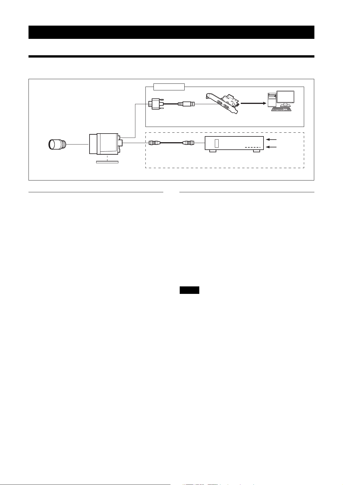
a Video camera module (this unit)
This is a small-size, high-resolution, camera that uses a
CMOS image sensor with a global shutter function.
b Camera cable
This is attached to the DC power input connector of the
unit and is used for the power supply and exchange of
trigger signals. For details about purchasing a cable,
consult a dealer.
c C-mount lens
Use a suitable lens to fit the camera pixel count.
d DC-700/700CE Camera Adaptor
This is connected to the unit to enable power supply
from an ordinary AC power source.
e VCT-333I Tripod Adaptor
This attaches to the bottom of the unit to mount the unit
on a tripod.
f USB 3.0 interface image input board
Install the board in the expansion slot of the host device
(computer or other device).
The camera can also be connected to a USB 3.0 port on
a computer, but the use of the input board is
recommended.
This document describes the case where the input board
is used.
System Components
ab
cd e
fg
g USB 3.0 cable
Connect to the USB connector on the rear panel of the
unit to send image signals and to receive control signals.
Use a Standard USB A to USB Micro B, USB 3.0 cable
that is compatible with the USB3 Vision standard.
For details about purchasing a cable, consult a dealer.
A system centered on the unit can comprise the
following components (available separately).
4
Page 5
Location and Function of Parts and Operation
Front/top/bottom
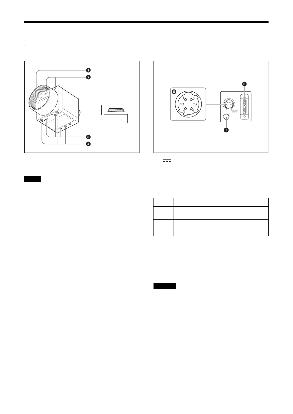
a
a Lens mount (C-mount)
Attach any C-mount lens or other optical equipment.
Note
Use a C-mount lens where the protrusion (a) extending
from the lens mount face (b) is 10 mm (13/32 inch) or
less.
When attaching a lens to the camera, note that the
resolution of the image that is output from the camera
may vary depending on the performance of the lens.
The performance of the same lens may also vary
depending on the aperture value.
If the resolution is insufficient, adjust the aperture value.
b
Rear
e (DC power input) connector (6-pin)
You can connect a camera cable to input a 12 V DC
power supply. The pin configuration of this connector is
as follows.
(Refer to part e above for the pin assignment of the
connector.)
Pin No. Signal Pin No. Signal
1DC input
(10.5 V to 15 V)
2 GPI1 (ISO +) 5 ISO –
3 GPI2/GPO2 6 GND
4 GPO3 (ISO +)
b Camera mount guide screw holes (top)
c Camera mount guide screw holes/Tripod
attachment screw holes (bottom)
When using a tripod, use these four screw holes to attach
a VCT-333I Tripod Adaptor.
For details, see “Mounting on a tripod” (page 7).
d Camera mount reference screw holes (bottom)
These precision screw holes are for securing the camera
module. Securing the unit with these holes minimizes
any optical axis alignment offset.
For details about the size of and position of guide holes
and reference holes, see “Dimensions” (page 44).
f USB connector (Micro B type)
Connect a USB 3.0 cable to control the camera module
from a host device and to send image signals from the
camera module. Power can be supplied from a USB 3.0
interface video input board or from a USB hub over the
USB 3.0 cable.
CAUTION
• For safety, do not connect the connector for peripheral
device wiring that might have excessive voltage to this
port. Follow the instructions for this port.
• Use a Standard USB A to USB Micro B, USB 3.0
cable that is compatible with the USB3 Vision
standard.
• USB 2.0 is not supported.
g Status LED (green)
Displays the unit status.
For details, see “Status LED” (page 30).
5
Page 6
Getting Started
Connections
USB 3.0
Standard A
Micro B
C-mount lens
Camera module
VCT-333I
Tripod Adaptor
USB 3.0 cable
Camera cable
Not required when using USB bus power from a USB connector
About the power supply
You can supply power to the unit using the following
methods.
Supplying power using the USB
connector
Power supply, camera control, and image output are all
supported using a single USB 3.0 cable.
Supplying power using the DC power
supply input connector
You can supply power via the DC power supply input
connector using the power adaptor.
Use the DC-700/700CE, which provides a stable power
source free from ripple or noise.
USB 3.0 interface
image input board
DC-700/700CE
Camera Adaptor
Host device (computer
or other device)
AC
TRIG
USB 3.0 connection
1
Insert the USB 3.0 interface image input board (not
supplied) into an expansion slot of the host device.
2
Connect the unit and host device using a USB 3.0
cable (not supplied). For details, see “Connecting
the cables” (page 7).
3
Check that the unit is successfully recognized on the
screen of the host device, and click the model name.
A viewer appears and displays the camera image.
Note
The method of operation varies depending on the
application used.
Heat dissipation
Heat dissipation may be required, depending on the
usage environment. For details, see “When mounting the
camera” (page 7).
About control of the camera module
To control the unit from a host device, USB 3.0
compatible software must be installed on the host
device.
To use the Sony USB 3.0 Software Development Kit
(SDK), download the software from the Sony website.
For details about software operation, refer to the
corresponding instruction manual.
6
Page 7
Connecting the cables
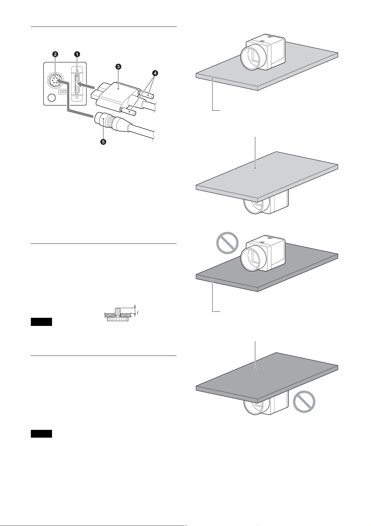
Connect the camera cable (5) to the DC power supply
input connector (
the USB connector (
image input board or a hub, you can operate the camera
even if you do not connect the camera cable to the DC
power supply input connector.
It you connect a USB 3.0 cable that has fastening
screws, turn the two screws (
secure the cable tightly.
Connect the other end of the USB 3.0 cable to the USB
3.0 interface image input board or a hub.
2), and connect a USB 3.0 cable (3) to
1). If using a USB 3.0 interface
4) on the connector to
Metallic base plate
Metallic base plate
Mounting on a tripod
To use a tripod, attach the VCT-333I Tripod Adaptor
(not supplied) to the camera module.
Use a tripod screw that protrudes (4) beyond the
mounting surface, as follows, and tighten it using a
screwdriver. Be sure that the protrusion (4) does not
exceed 5.5 mm (0.2 in.) in length.
4: 4.5 mm to 5.5 mm
Note
When attaching the tripod adaptor (not supplied), use
the screws provided with the tripod adaptor.
When mounting the camera
When the value read from temperature sensor is above
75 °C (167 °F), heat dissipation is required.
Use in environments where the difference with the
ambient temperature is 32 °C (90 °F) or less.
To facilitate heat dissipation from the unit and maintain
performance, mount the camera to a metallic plate.
Plate that prevents heat dissipation
(made of wood, resin, etc.)
Plate that prevents heat dissipation
(made of wood, resin, etc.)
Notes
• When mounting the camera on the metallic plate,
secure the camera by using the reference screw holes
on the camera (page 5) and screws.
• Do not mount the camera on a plate made of a
material, such as wood or resin, that prevents heat
dissipation.
7
Page 8
Functions
V
Default value for each item is underlined.
Trigger Signal Input
Trigger signals can be input via pins 2, 3, and 4 of the DC power supply input connector, or by software command.
Switchover of the trigger signal can be changed using TriggerSource. For details, see “Trigger Control” (page 17).
Trigger signal polarity
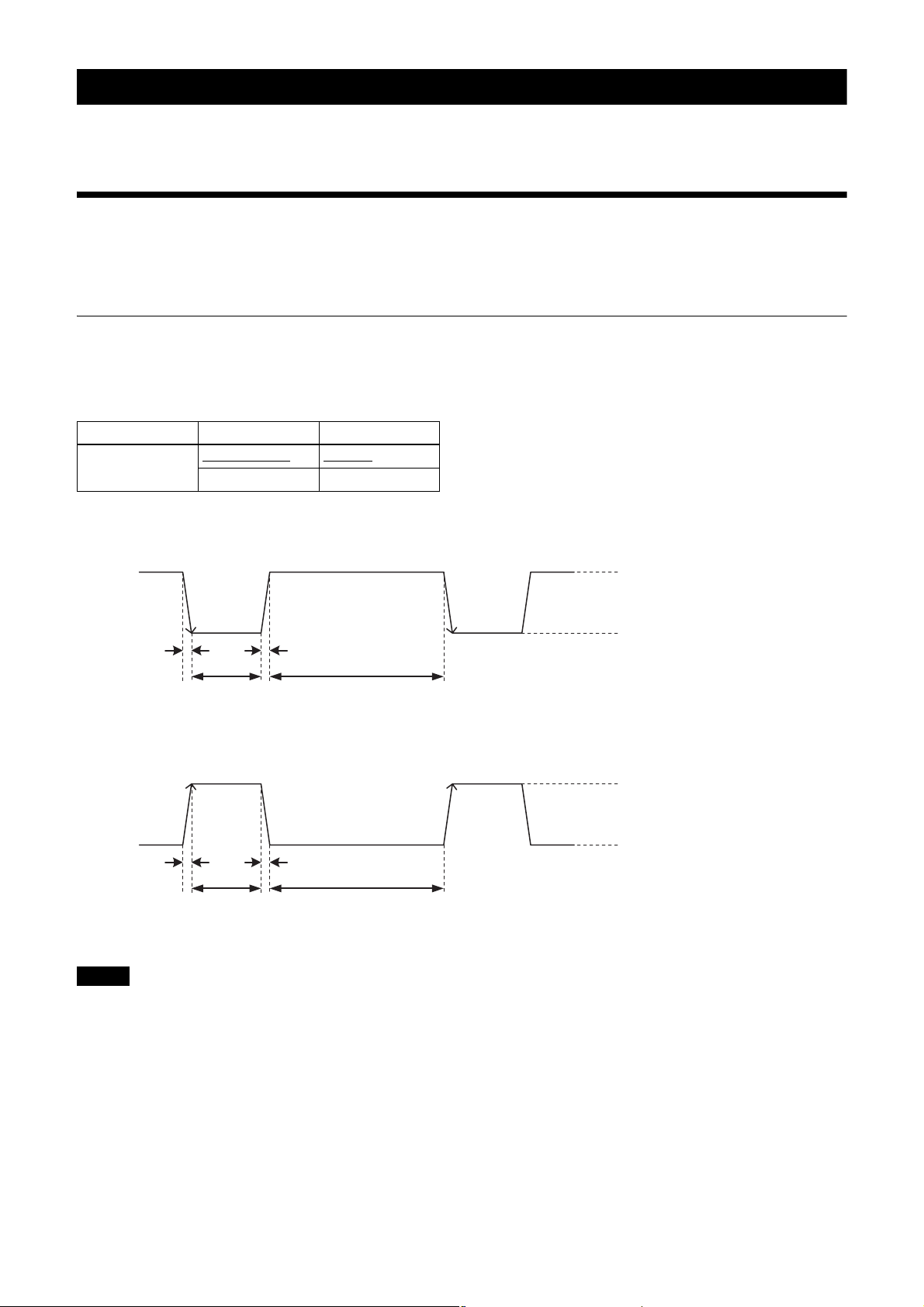
Positive polarity refers to a trigger signal activated by a Low to High rising edge, or High-level interval. Negative
polarity refers to a trigger signal activated by a High to Low falling edge, or Low-level interval. The default value of the
camera is negative polarity.
Feature Parameter Setting
TriggerActivation FallingEdge (0)
RisingEdge (1) Positive
DC power supply input connector specifications
Negative
5 V to 24 V (pin 2 of the DC power supply
input connector)
3.5 V to 5.5 V (pin 3 of the DC power
supply input connector)
0 V to 0.4 V
2.0 µs or less2.0 µs or less
10 µs to 2 s
10 µs to 2 s
Notes
1 frame cycle or longer
Trigger input polarity = Negative
2.0 µs or less2.0 µs or less
1 frame cycle or longer
Trigger input polarity = Positive
to 24 V (pin 2 of the DC power supply
5
input connector)
3.5 V to 5.5 V (pin 3 of the DC power
supply input connector)
0 V to 0.4 V
• When inputting a trigger signal to the camera using the DC-700/700CE, use 5 V DC or lower as the logical high level.
• Make sure to supply power to the unit and confirm that the unit is operating before inputting a trigger signal. If you
input a trigger signal to the unit without the power supplied, this may cause a malfunction of the camera.
8
Page 9
GPIO Connector
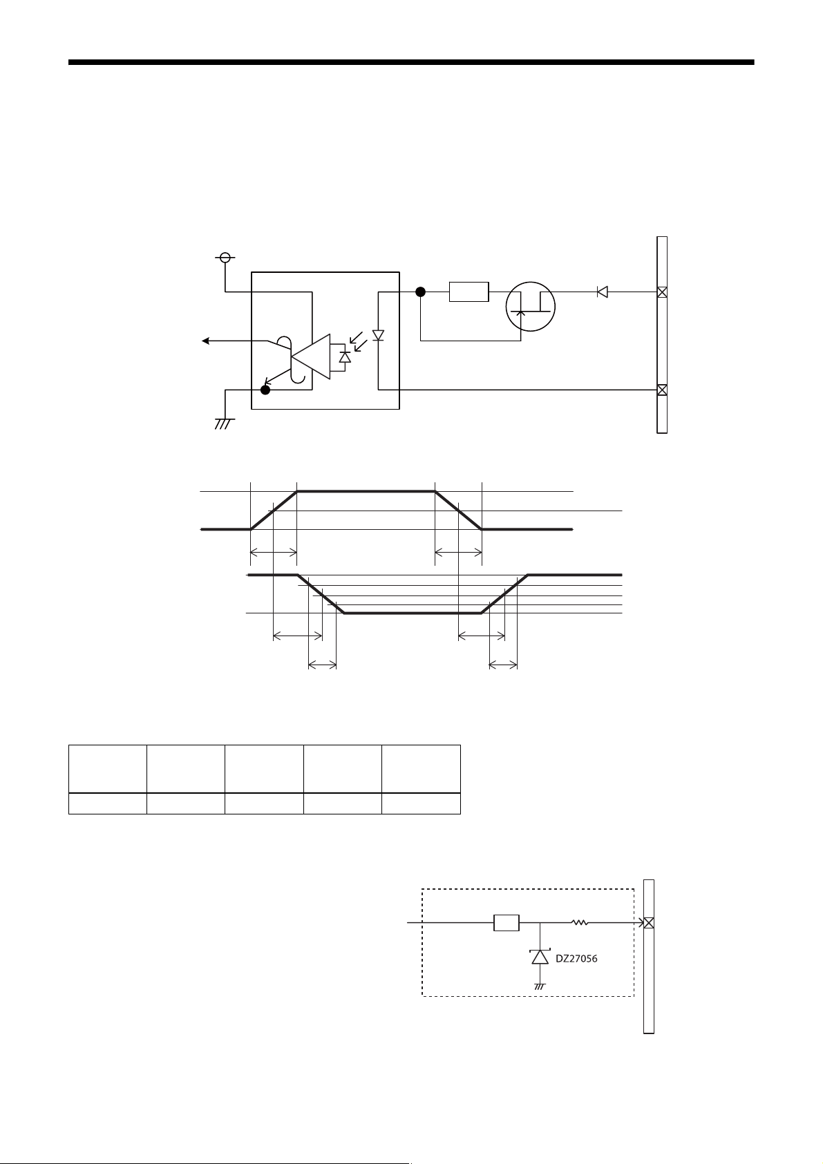
Pin 2 of the DC power supply connector is a GPI connector, pin 3 can be set as either a GPI or GPO connector, and pin
4 is a GPO connector. The default trigger source is pin 2 of the DC power supply input connector (GPI1). If connecting
an external device to the GPI or GPO connector, refer to the circuit specifications below.
GPI circuit specifications
DC power supply input connector
3.3V
ACPL-M60
GPI1
Input level (Low: 0 V to 0.4 V, High: 5 V to 24 V)
5 V
0 V
**
180
MMBF4393LT1G
#2
DA2710100L
#5
50%
3.3 V
0 V
TDF
FT
* Rising edge of the input signal should be as fast as possible.
Example
Input
voltage
[V]
5.0 167 297 192 358
TDF
[ns]
FT
[ns]
TDR
[ns]
RT
[ns]
GPIO circuit specifications
GPI2/GPO2
TDR
RT
SN74LVC1T45
90%
50%
10%
DC power supply input connector
180 Ω
#3
Input level (Low: 0 V to 0.4 V, High: 3.5 V to 5.5 V)
Output level (0 V to 3.3 V)
9
Page 10
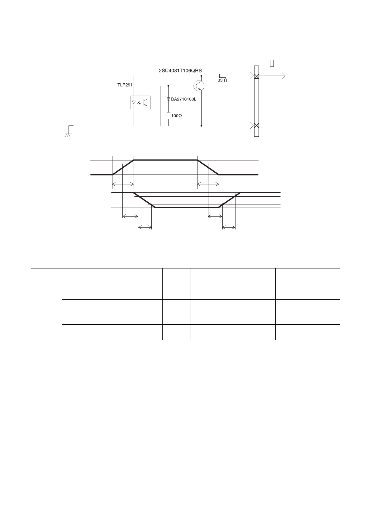
GPO circuit specifications
GPO3
3.3 V
0 V
DC power supply
input connector
#4
#5
External power source
(3.3 V to 24 V)
Pull up resistance
50%
3.3 V
0.9 V
TDF
FT
TDR
RT
90%
10%
Example
When connecting to an external power supply, be sure to use a pull-up resistor to limit the current to 50 mA or less.
Ambient
temperature
Supply voltage
of the output
[V]
3.3 470 Ω 5.07 0.75 0.49 24 35 0.916
5.0 820 Ω 4.98 0.73 0.63 28 46 0.909
12.0 Two 2200 Ω resistors in
24.0 Eight 8200 Ω resistors
Pull up resistance
(Use 1/16 W)
parallel
in parallel
Current
[mA]
TDF
[µs]
FT
[µs]
TDR
[µs]
RT
[µs]
Output
voltage
9.87 0.71 1.05 36 64 1.112
21.85 0.73 1.45 45 76 1.571
[V]
10
Page 11
Partial Scan
Binning (XCU-CG160
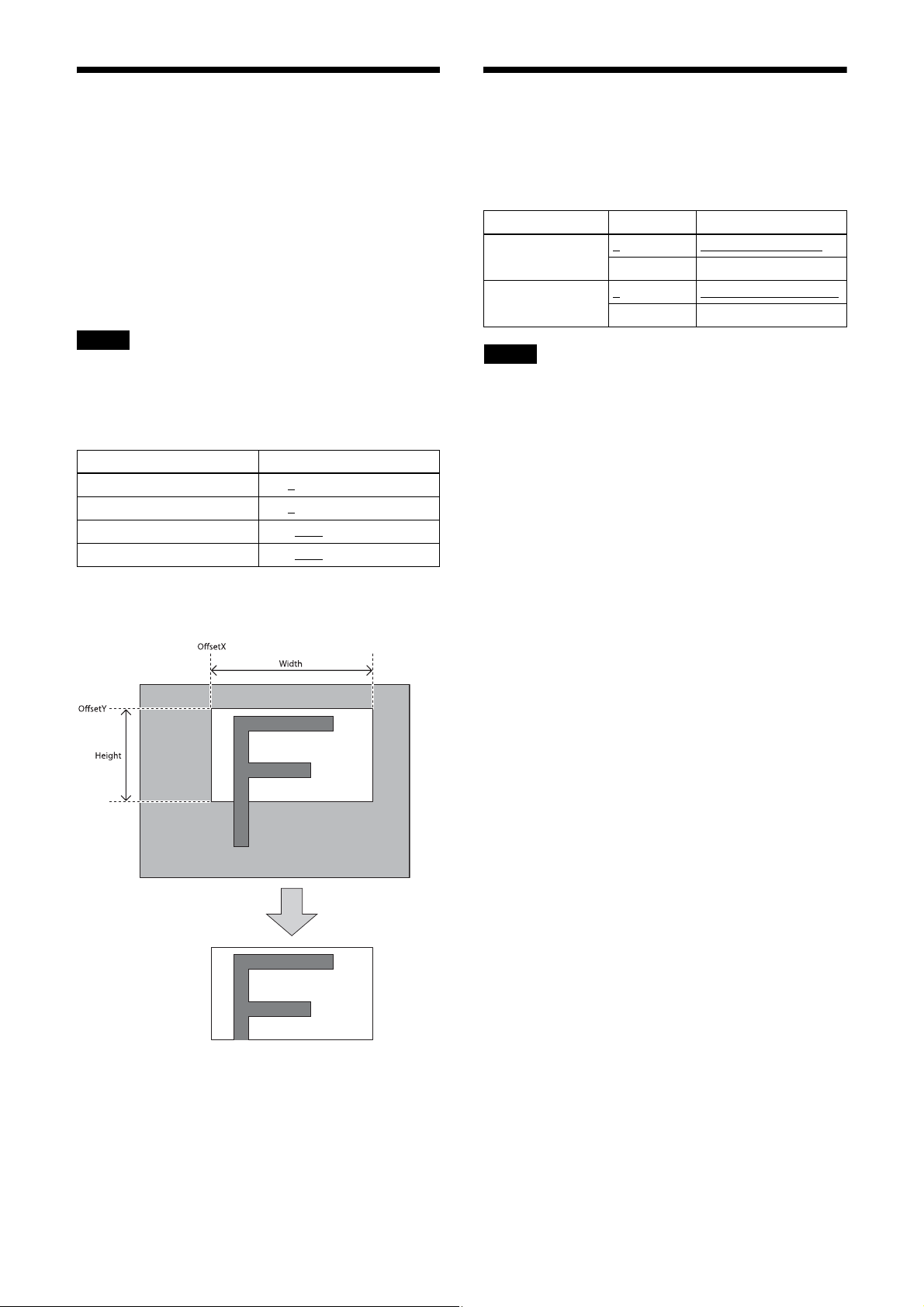
Only an area selected from the effective pixel area can
be scanned. The area size is selected by Height and
Width, and the read start point is selected by OffsetX
and OffsetY. Reducing Height increases the frame rate,
but changing Width does not change the frame rate.
Partial scan can be set with or without a trigger.
OffsetX and OffsetY relate to Width and Height as
follows:
OffsetX + Width ≤ Width (maximum value)
OffsetY + Height ≤ Height (maximum value)
Note
Since the shutter setting has priority, use a shutter speed
high enough to enable partial scan at a higher frame rate.
Configurable range
Feature Parameter
OffsetX 0 to 8
OffsetY 0 to 4
Width 16 to 1440
Height 16 to 1080
to 1440
to 1072
to 1456
to 1088
only)
Adding two pixels in the vertical and horizontal
directions achieves higher sensitivity and frame rate.
Feature Parameter Setting
BinningVertical 1
2 Vertical binning is on
BinningHorizontal 1
2 Horizontal binning is on
Notes
• To increase the frame rate for binning, use the shutter
at a sufficiently high speed.
• When using binning, the configurable values for
OffsetX, OffsetY, Width, and Height are halved and
change in increments of 2.
Vertical binning is off
Horizontal binning is off
Configurable values
OffsetX, OffsetY, Width, Height: Increments of 4
Partial scan
11
Page 12
Camera Mode
“FAST” mode prioritizes the frame rate, and is set by
default.
The frame rate upper limit of “FAST” mode is higher
than for “NORMAL” mode, but the available functions
are limited.
When correcting defects/shading in “FAST” mode,
detect and save the defects/shading in “NORMAL”
mode and then return to “FAST” mode.
Reboot the unit to apply the change in camera mode.
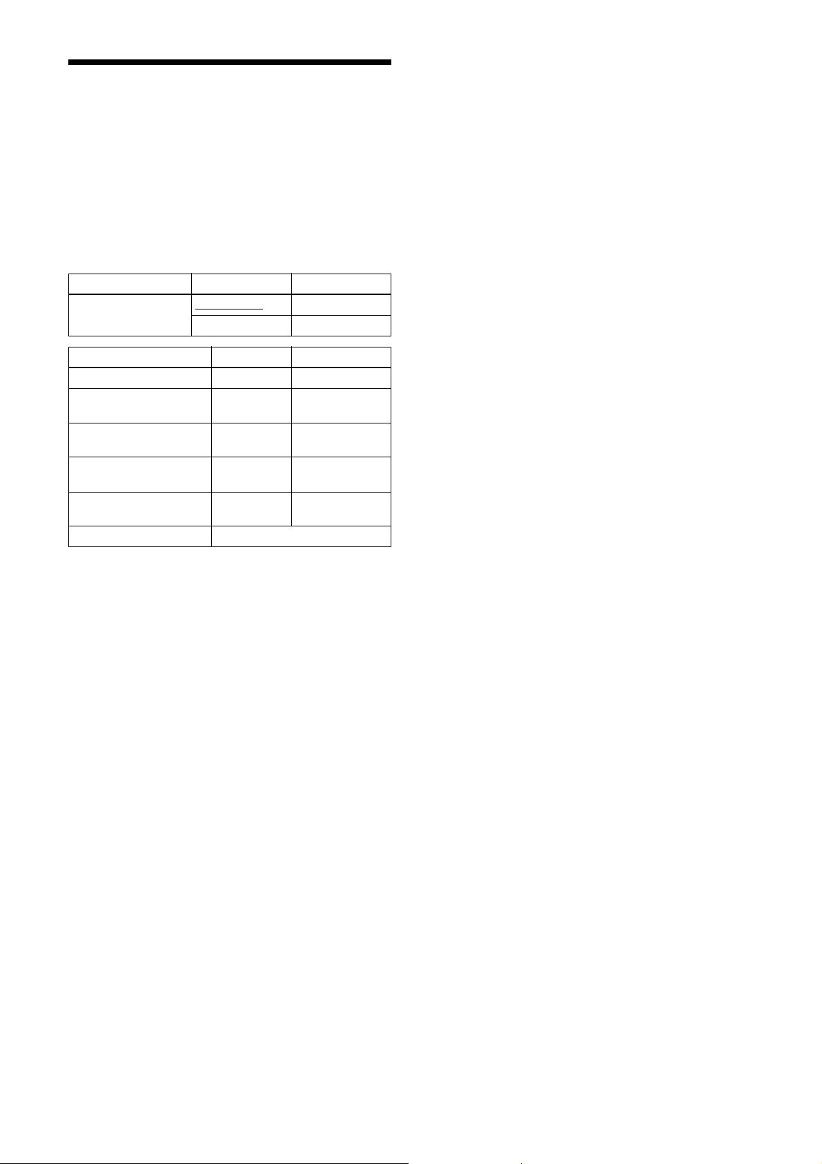
Feature Parameter Setting
CameraModeSelector FastMode (0)
NormalMode (1) NORMAL
Function FAST NORMAL
Maximum frame rate 100 fps 56 fps
Defect detection function
(page 30)
Defect correction function
(page 30)
Shading detection function
(page 31)
Shading correction
function (page 31)
Output format See “Output Format” (page 14).
– z
zz
– z
zz
FAS T
z: Available function, –: Unavailable function
12
Page 13
Multi ROI
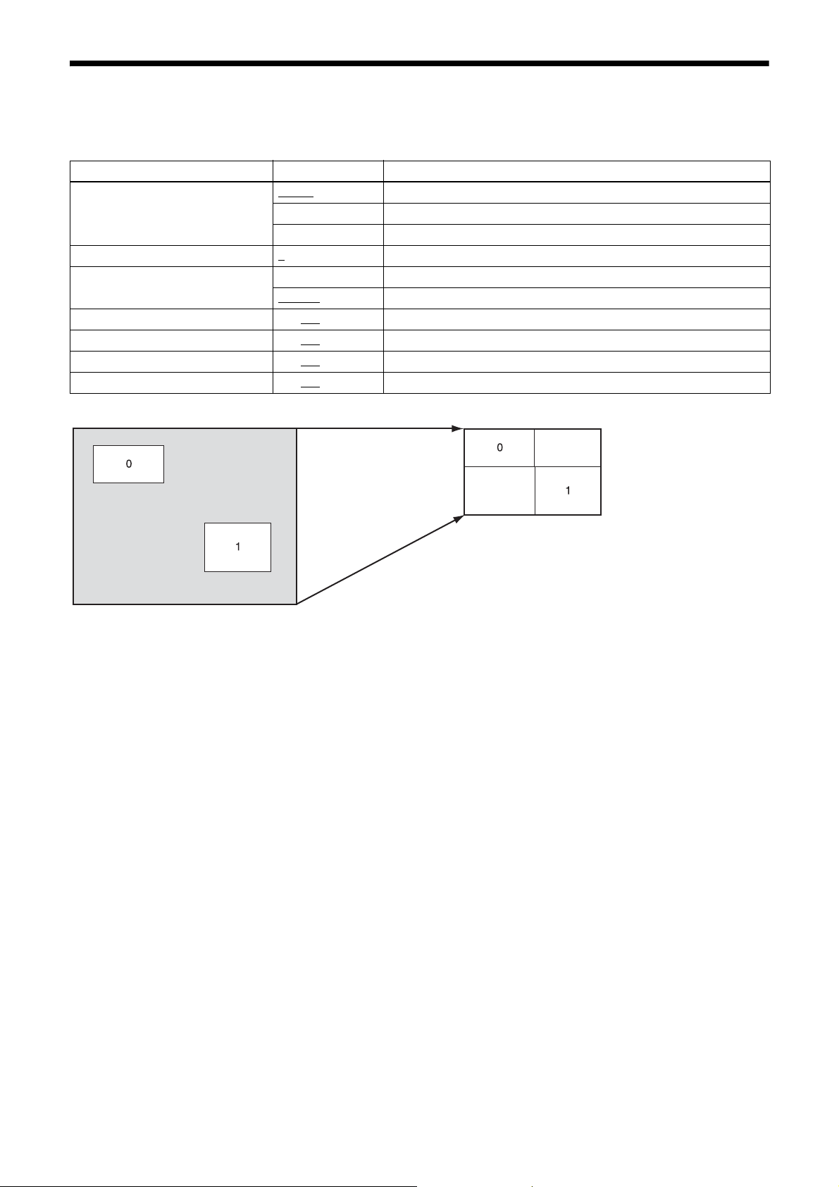
You can set and read two arbitrary rectangular areas from the effective pixel area.
By reading only the required parts, you can shorten the time it takes to read.
Feature Parameter Setting
MultiROIMode Off (0)
MultiROISelect 0
MultiROIEnable False (0) The area designated in MultiROISelect is Off.
MultiROIWidth 4 to 128
MultiROIHeight 4 to 128
MultiROIOffsetX 0 to 128
MultiROIOffsetY 0 to 128
Before partial scan After partial scan
All areas Off
On (1) All areas On
Highlight (2) Displays the specified region highlighted.
to 1 Designates the number of the area for which to change parameters.
The area designated in MultiROISelect is On.
True (1)
to 1456 Horizontal size of the area
to 1088 Vertical size of the area
to 1452 Horizontal position of the area
to 1084 Vertical position of the area
13
Page 14
Output Format
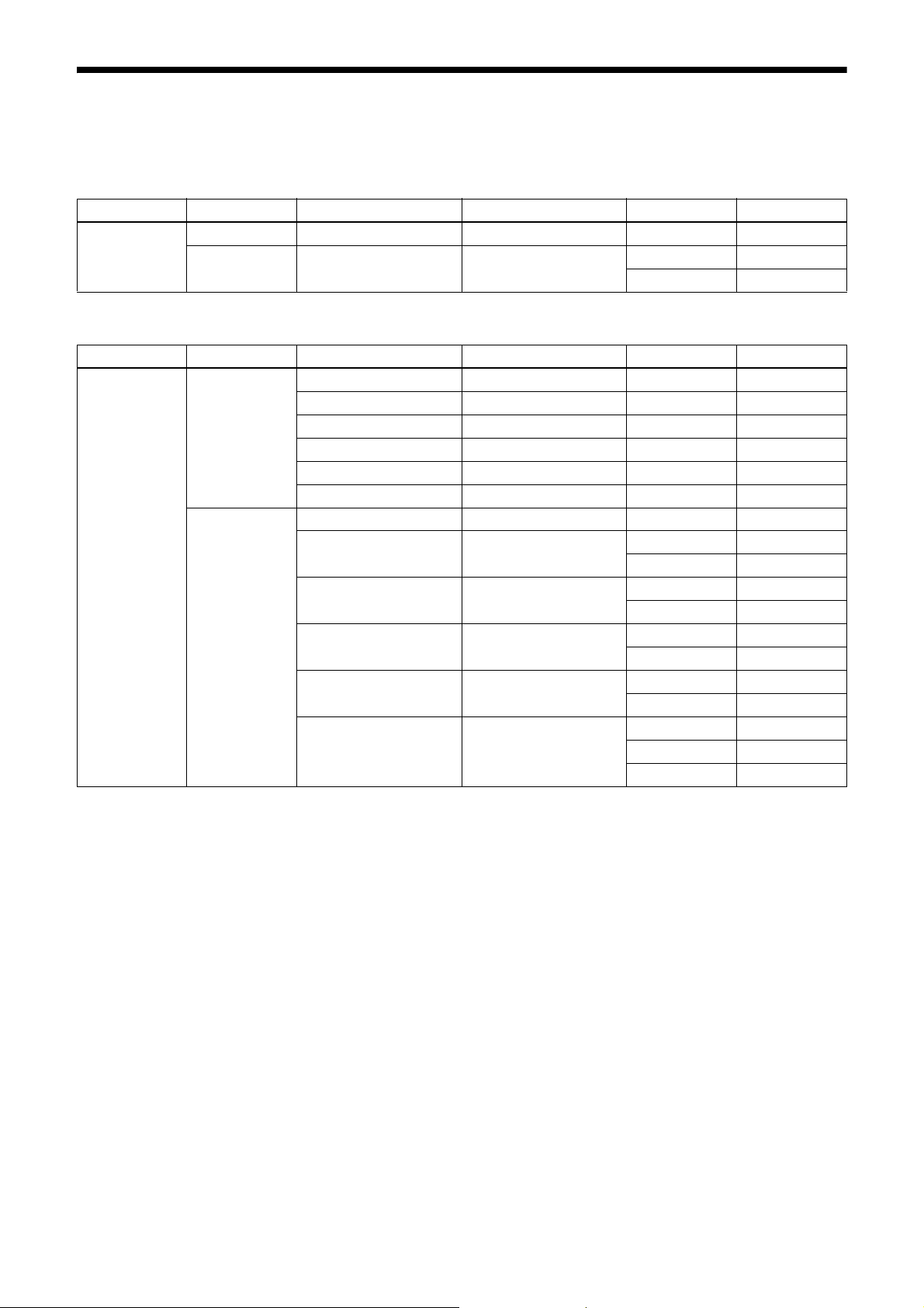
The configurable pixel formats are as follows:
XCU-CG160 (monochrome camera)
Feature Camera mode ReverseX ReverseY Parameter Setting
PixelFormat FAST False or True False or True 0x01080001 Mono8
NORMAL False or True False or True 0x01080001 Mono8
0x010C0047 Mono12p
XCU-CG160C (color camera)
Feature Camera mode ReverseX ReverseY Parameter Setting
PixelFormat FAST False or True False or True 0x01080001 Mono8
False False 0x01080009 BayerRG8
False True 0x0108000A BayerGB8
True False 0x01080008 BayerGR8
True True 0x0108000B BayerBG8
False or True False or True 0x02180015 BGR8
NORMAL False or True False or True 0x01080001 Mono8
False False 0x01080009 BayerRG8
0x010C0059 BayerRG12p
False True 0x0108000A BayerGB8
0x010C0055 BayerGB12p
True False 0x01080008 BayerGR8
0x010C0057 BayerGR12p
True True 0x0108000B BayerBG8
0x010C0053 BayerBG12p
False or True False or True 0x02180015 BGR8
0x0218005B YCbCr8
0x0210003B YCbCr422_8
*1 Monochrome output due to binning.
*2 Image size is half of standard size.
*2
*1
14
Page 15
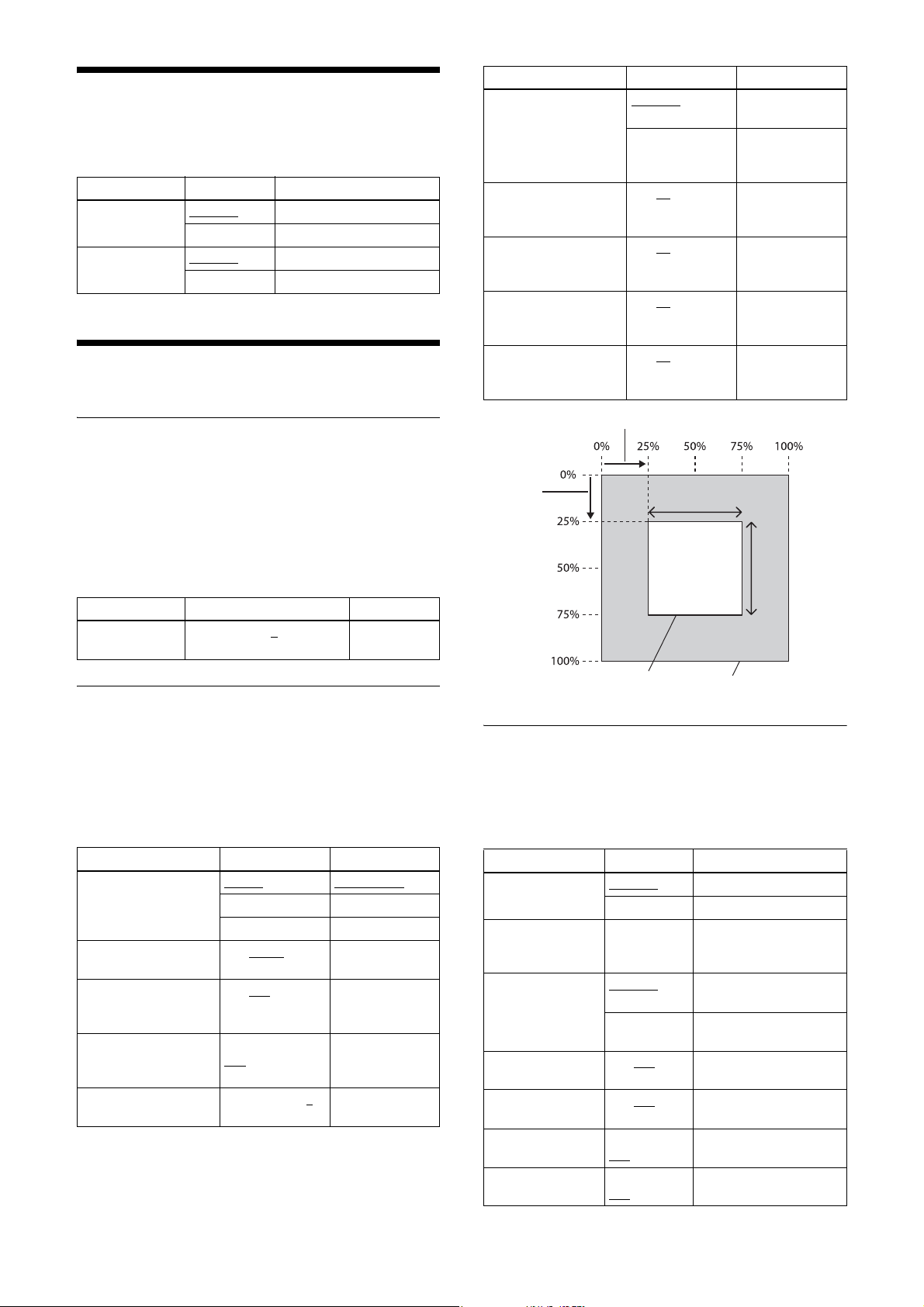
Image Flip
Flips an image vertically and horizontally.
Reboot the unit to reflect the changes of the setting.
Feature Parameter Setting
ReverseX False (0)
True (1) Flip horizontally
ReverseY False (0)
True (1) Flip vertically
Off (no flip)
Off (no flip)
Gain
Feature Parameter Setting
GainAutoHighlight False (0) AGC detection
True (1) AGC detection
GainAutoAreaWidth 1 to 50
GainAutoAreaHeight 1 to 50
GainAutoAreaOffsetX 0 to 25
GainAutoAreaOffsetY 0 to 25
to 100 Horizontal size of
to 100 Vertical size of
to 99 Horizontal
to 99 Vertical position
frame is hidden
frame is
displayed
AGC detection
frame
AGC detection
frame
position of AGC
detection frame
of AGC detection
frame
Manual gain
The manual gain can be finely set in 0.1 dB increments.
Although the configurable lower/upper limit values of
the gain are slightly different for each camera, the
configurable values for the GainAnalog parameter are
–1 dB or lower to +27 dB or higher.
The rage of the gain setting that guarantees image
quality is 0 dB to 18 dB.
Feature Parameter Setting
GainAnalog –1 or lower to 0
higher
to +27 or
Gain dB unit
Auto gain (AGC)
By setting auto gain, the gain is automatically adjusted
according to the imaging environment. AGC operates so
that the average level within a detection frame satisfies
the GainAutoLevel setting. The AGC detection frame is
set to the central region by default. The detection frame
can be displayed and the detection area can be changed.
Feature Parameter Setting
GainAuto Off (0) Manual gain
Once (1) One-push AGC
Continuous (2) Continuous AGC
GainAutoLevel 0 to 11264
16383
GainAutoSpeed 1 to 192
GainAutoUpperLimit –1 or lower to
+18
higher
GainAutoLowerLimit –1 or lower to 0
to +27 or higher
to
to 256 AGC
to +27 or
AGC target level
(14 bits)
convergence
speed
AGC upper limit
AGC lower limit
GainAutoAreaOsetX
GainAutoAreaOsetY
Detection frame area
GainAutoAreaWidth
Output image
GainAutoAreaHeight
Area gain
A separate digital gain can be set for up to 16 rectangular
areas.
If multiple rectangular areas are duplicated, the gain
value of the low-numbered area takes priority.
Feature Parameter Setting
AreaGainEnableAll False (0)
True (1) Gain in all areas set to On
AreaGainSelect 0 to 15 Designates the number of
AreaGainEnable False (0)
True (1) Gain of area specified by
AreaGainWidth 0 to 128
Width
AreaGainHeight 0 to 128 to
Height
AreaGainOffsetX OffsetX to
128
AreaGainOffsetY OffsetY to
128 to Height
Gain in all areas set to Off
the area for which to
change parameters.
Gain of area specified by
AreaGainSelect set to Off
AreaGainSelect set to On
to
Horizontal size of area
Vertical size of area
Horizontal position of
to Width
*
area
Vertical position of area
*
*
*
15
Page 16
Feature Parameter Setting
AreaGainValue 0 to 256 (×1)
to 8191
* Specify the area size and position of the area gain in absolute
coordinate values relative to the effective pixels. Therefore, the range
of the area size and position needs to be set within the readout range.
Gain value of area
Shutter (Exposure)
Configuration method
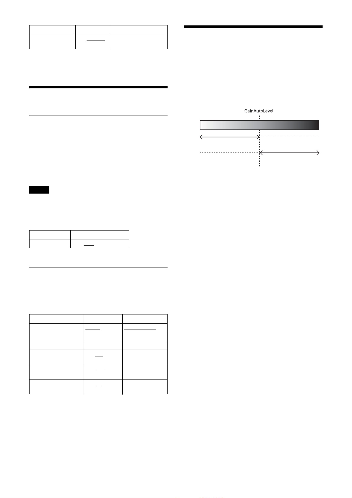
Combination of Continuous AGC and Continuous AE
AGC and AE operate together to adjust the level
automatically with GainAutoLevel as the target level.
When the environment starts getting dark and AE
reaches the upper limit, AGC starts to operate.
Bright Dark
The setting is configured in µs units. The default shutter
value is the value with the frame rate maximized. During
free run operation, the frame rate is reduced by setting a
value bigger than the default shutter value. If you do not
prioritize the image quality, you can set it to a value of
up to 60 seconds during operation. If the exposure time
is long, it will be easier to see the pixel defects.
Note
The exposure times that can be set varies depending on
the mode.
Check the actual value by reading out after completing
settings.
Feature Parameter
ExposureTime 1* to 9600 to 60000000
* The minimum value varies depending on the settings.
Auto exposure (AE)
The shutter is set automatically by detecting the output
level. The target level is the same as the value of
GainAutoLevel. This can be performed in conjunction
with auto gain.
AE
AGC
ExposureAuto
LowerLimit
ExposureAuto
UpperLimit
GainAuto
LowerLimit
GainAuto
UpperLimit
Feature Parameter Setting
ExposureAuto Off (0)
Once (1) One-push AE
Continuous (2) Continuous AE
ExposureAutoSpeed 1 to 192
ExposureAutoUpperLimit
ExposureAutoLowerLimit
to 256 AE convergence
1 to 9600
60000000
1 to 10
60000000
to
to
Manual shutter
speed
AE upper limit
AE lower limit
16
Page 17
Trigger Control
Free run/trigger mode
Free run
The camera operates without a trigger signal and performs image output operation continuously after the shutter
(exposure) is finished. The horizontal and vertical timing signals are generated within the camera. During free-run
operation, image pickup timing cannot be controlled. In free-run operation, adjustment is made automatically to achieve
the maximum frame rate according to the shutter setting.
Trigger mode
Exposure is started by detecting an external input trigger signal. When ExposureMode is set to Timed, exposure is
started by detecting the rising or falling edge of the trigger signal (trigger edge detection performed based on the set
shutter value). When ExposureMode is set to TriggerWidth, trigger width detection is performed (exposure during the
trigger signal pulse width).
Feature Parameter Setting
TriggerMode Off (0)
On (1) Trigger mode
Trigger source
Free run
A trigger source can be input via the DC power supply input connector or via software command (TriggerSoftware).
Feature Parameter Setting
TriggerSource Line1 (0)
Line2 (1) Pin 3 of the DC power supply input connector
Software (4) Software
Pin 2 of the DC power supply input connector
In trigger mode (TriggerMode=On)
Feature Parameter Setting
ExposureMode Timed (0)
TriggerWidth (1) Trigger width detection
Note
Trigger edge detection
A combination of TriggerSource Software setting and ExposureMode TriggerWidth setting is not supported.
Trigger edge detection
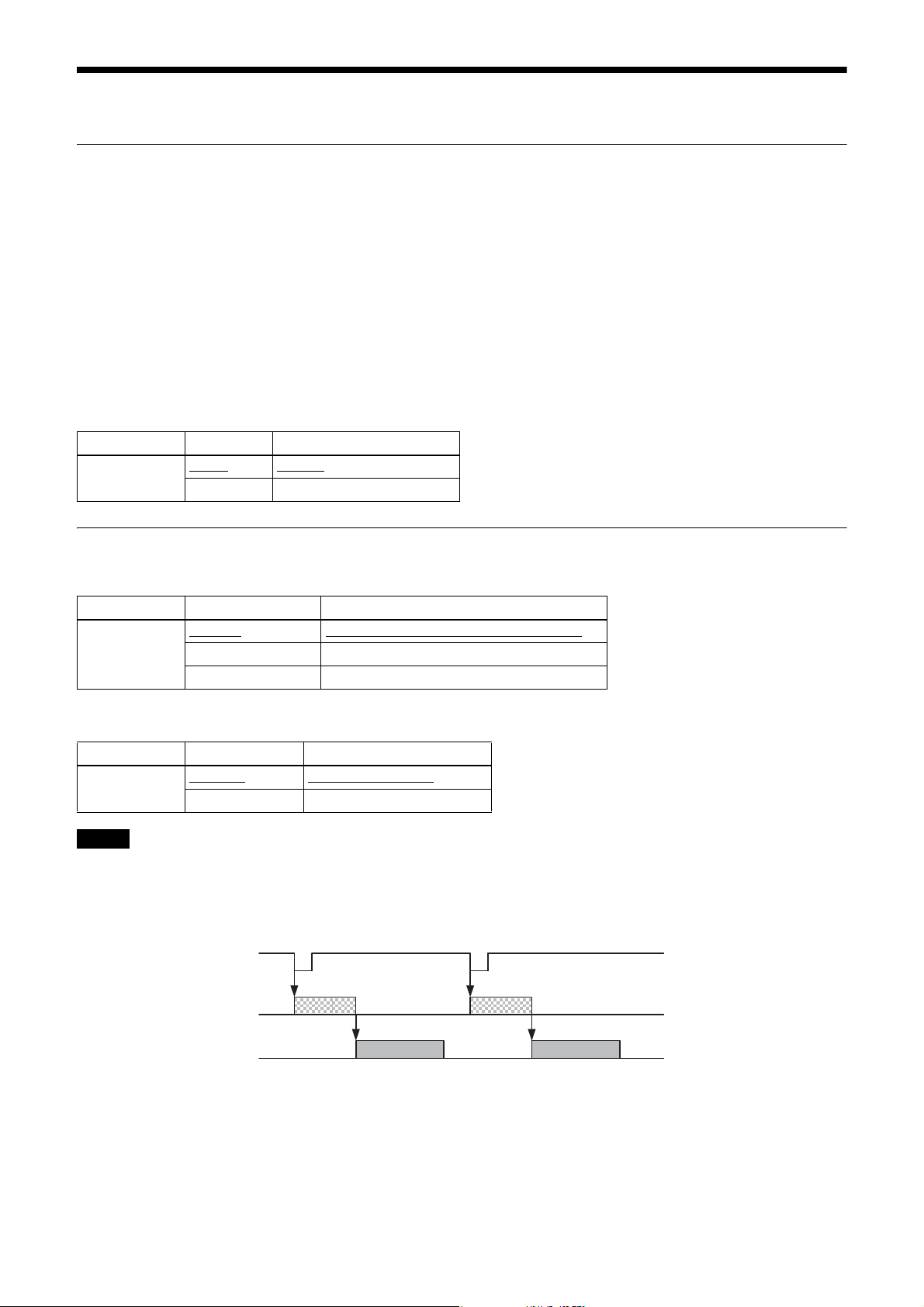
The figure shows trigger signal negative polarity (falling-edge detection).
Trigger signal
Exposure
Sensor output
17
Page 18
Trigger width detection
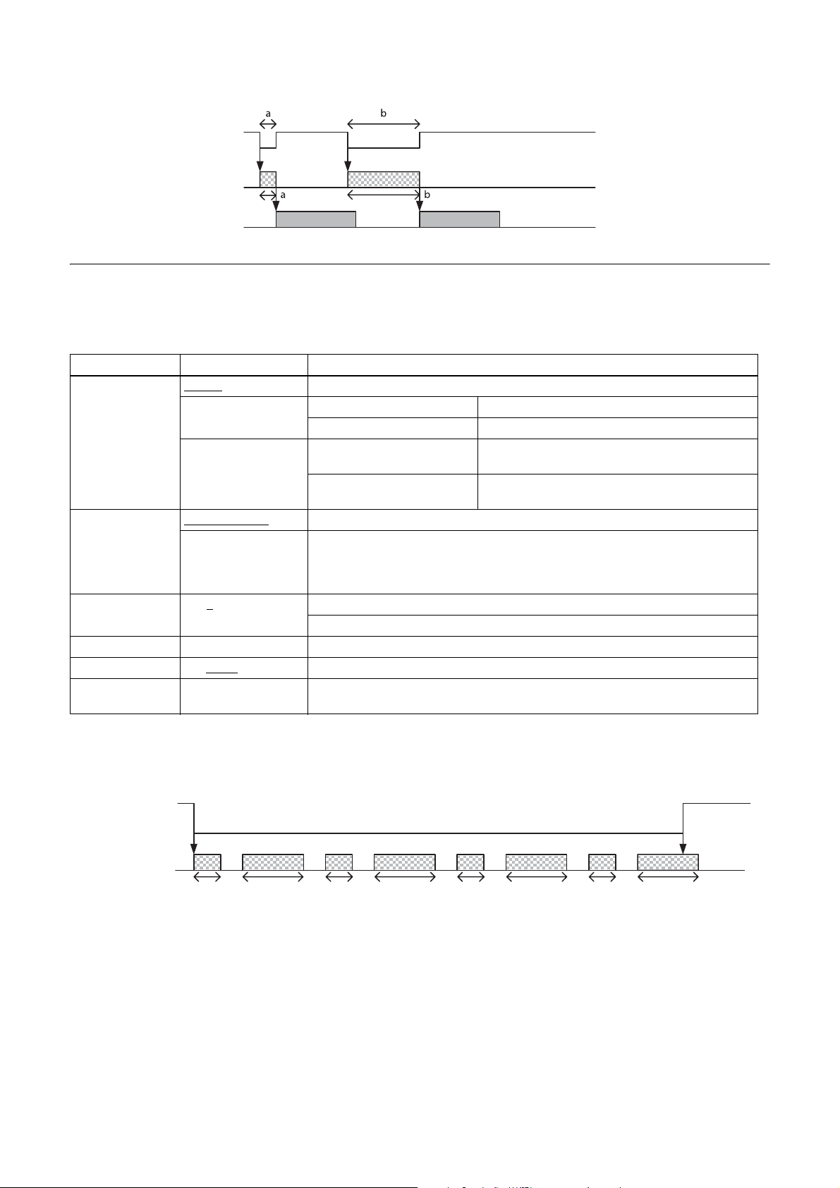
The figure shows trigger signal negative polarity (Low-level width detection).
Trigger signal
Exposure
Sensor output
Burst trigger
Exposure can be repeated with a single trigger signal. Two modes are available: a mode that repeats a single exposure
time and a mode that alternately repeats two exposure times. You can specify the number of exposures and the interval
between repeatedly setting the trigger signal on.
Feature Parameter Setting
BurstTriggerMode Off (0)
BurstTriggerPeriod FrameCount (0)
BurstFrameCount 0 to 1
BurstForceStop Forced termination of repeated exposure
Exposure2Time 1 to 83998
Exposure2Ratio ×1 (1), ×2 (2), ×4 (4),
SingleExposureMode
(1)
DualExposureMode (2) Upon trigger edge detection Exposes for periods set in ExposureTime and
Exposes only the number of times set in BurstFrameCount.
TriggerDuration (1) Performs burst exposure while the input trigger is on. However, burst exposure is
to 65533 0: Repeats continuously
to 60000000 Second exposure time during trigger edge detection
×8 (8), ×16 (16)
Upon trigger edge detection Exposes for the period set in ExposureTime.
Upon trigger width detection Exposes for the range of trigger width.
ExposureTime2 alternatively.
Upon trigger width detection Exposes for periods in trigger width and trigger width
× Exposure2Ratio alternately.
terminated when it reaches BurstFrameCount.
Enabled when ExposureMode is in edge detection mode. Disabled in width detection
mode.
1 or more: Exposure for designated number of times
Value to determine the second exposure time of trigger width detection. The first
exposure time (trigger width) multiplied by this value is the second exposure time.
Trigger edge detection (ExposureMode = Timed)
BurstTriggerPeriod=TriggerDuration
BurstTriggerMode=DualExposureMode
Trigger signal
Exposure
ExposureTime
The continuous exposure ends when either one of the following conditions occurs.
• Trigger signal Off is detected
• The number of times of exposure reaches the number specified in BurstFrameCount
Exposure2Time
ExposureTime Exposure2Time ExposureTime Exposure2Time ExposureTime Exposure2Time
18
Page 19
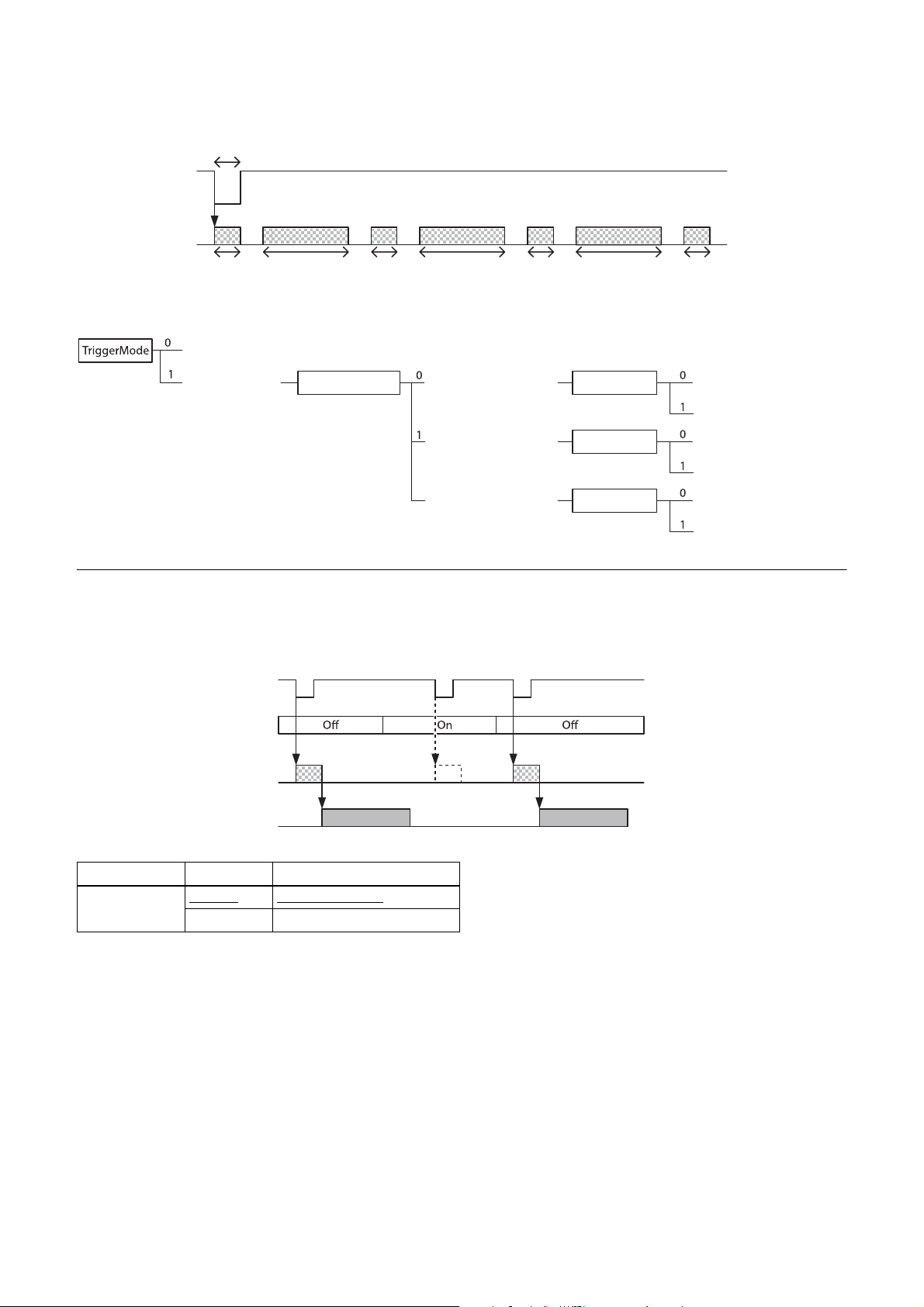
Trigger width detection (ExposureMode = TriggerWidth)
BurstFrameCount = 7
BurstTriggerMode=DualExposureMode
Trigger signal
Exposure
T
T × Exposure2RatioTT T × Exposure2Ratio T T × Exposure2Ratio T
Trigger states
Free run
Trigger mode Off (normal trigger)
BurstTriggerMode
SingleExposureMode
2
DualExposureMode
ExposureMode
ExposureMode
ExposureMode
Trigger edge detection
Trigger width detection
Trigger edge detection
Trigger width detection
Trigger edge detection
Trigger width detection
Trigger inhibit
Trigger input can be disabled. This function is effective when disabling the trigger signal to a specific camera in an
environment where multiple cameras are triggered by the same trigger signal, and when preventing false operations
caused by noise on the trigger signal line (due to the installed environment).
Trigger signal
Trigger inhibition
Exposure
Sensor output
Trigger
disabled
Feature Parameter Setting
TriggerInhibit False (0)
Trigger is accepted
True (1) Trigger is not accepted
19
Page 20
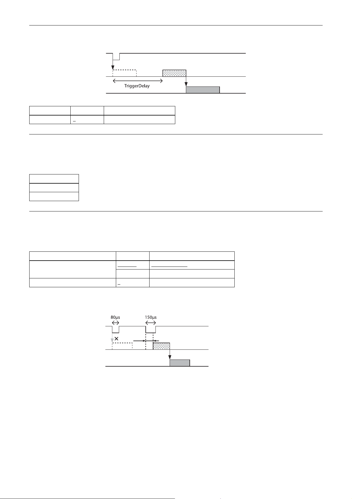
Trigger d elay
The camera can delay the trigger signal.
Trigger signal
Exposure
Sensor output
Feature Parameter Setting
TriggerDelay 0
to 4000000 Trigger delay [µs]
Trigger counter
This counts the number of accepted triggers. Triggers that have been removed because they exceed the trigger range
limit and triggers input with invalid timing are not counted. The trigger counter returns to 0 when the upper limit
(2147483647) is reached. The trigger counter can be reset to 0 by issuing TriggerCounterReset.
Feature
TriggerCounter
TriggerCounterReset
Trigger range limit
Only signals in the set trigger width can be accepted as a trigger signal. This functions as a noise filter, which removes
chattering or disturbance noise in the trigger signal line. When a trigger signal is input, exposure is started with a time
lag set by the trigger range set value. No image is output outside the trigger signal width set range.
Feature Parameter Setting
TriggerAcceptanceRangeEnable False (0)
True (1) Trigger range on
TriggerAcceptanceRangeLowerLimit 1
Trigger range operation example
ExposureTime=300, TriggerAcceptanceRangeLowerLimit=100 in the figure.
Trigger signal
Exposure
Sensor output
Trigger range off
to 2000000 Trigger range lower limit [µs]
100μs
20
Page 21
Frame Rate
Auto frame rate
The read cycle is set to allow the frame rate to be the maximum value automatically, according to the current shutter
setting and the partial scan setting in free-run operation (shutter has priority). The next exposure is performed during
image output, and the next image output is started immediately after finishing all image output. The frame rate is
reduced by setting a shutter time longer than the image output time.
Feature Parameter Setting
AcquisitionFrameRateAuto False (0) Auto frame rate off
Auto frame rate on
True (1)
Specifying the frame rate
The frame rate of the image output can be specified in free-run operation. Enter the value of the frame rate [fps]. A frame
rate faster than the fastest frame rate cannot be set.
Feature Parameter Setting
AcquisitionFrameRate 0.0625 to 100
* The upper limit varies depending on the partial scan setting.
to 4000 * Frame rate [fps]
Displaying the frame rate
The current frame rate during auto frame rate operation is displayed.
Feature
AcquisitionFrameRateActual
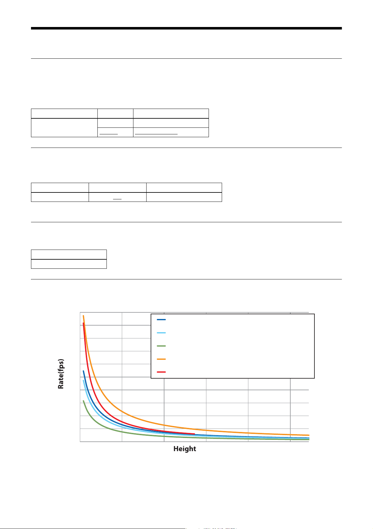
Fastest frame rate for partial scanning
The fastest frame rate varies depending on the Height parameter for partial scanning.
2000
XCU-CG160 Normal Mode:Mono12p, Mono8
1800
1600
1400
1200
1000
800
600
XCU-CG160C Normal Mode:Mono8, BayerRG12p, BayerRG8
XCU-CG160C Normal Mode:YCbCr422_8
XCU-CG160C Normal Mode:BGR8,YCbCr8
XCU-CG160 Fast Mode:Mono8
XCU-CG160C Fast Mode:BayerRG8
XCU-CG160C Fast Mode:Mono8, BGR8
400
200
0
0 200 400 600 800 1000
21
Page 22
Frame Counter
You can read out the number of frames captured by the camera.
The counter can be reset.
Feature
FrameCounter
FrameCounterReset
Timing Chart
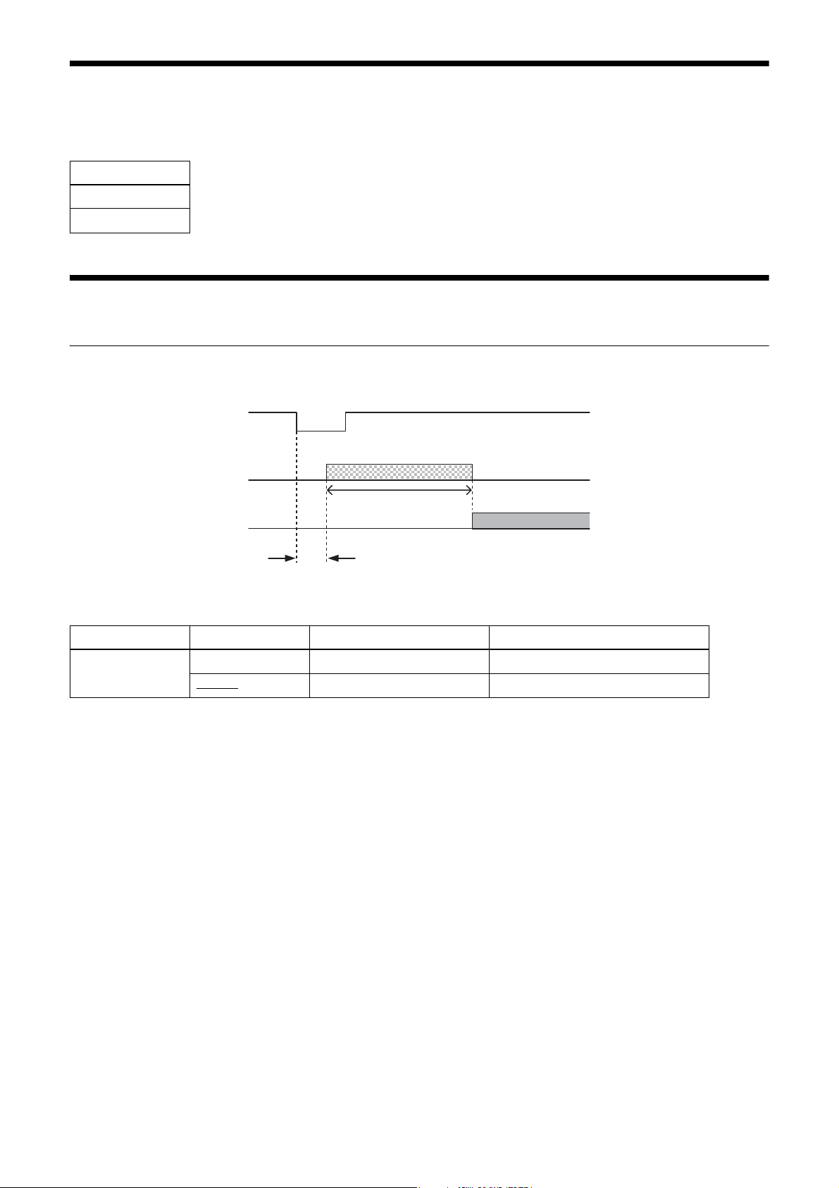
Trigger latency/Exposure time
The values of trigger latency (time from trigger acceptance to exposure start) and exposure time are as follows.
Trigger signal
Exposure
Exposure time
Sensor output
Trigger latency
Feature Parameter Trigger latency Exposure time
TriggerFastMode False (0) Approx. 8 µs to approx. 82 µs ExposureTime ± (approx. 0 µs to 27 µs)
True (1)
Approx. 0.2 µs ExposureTime ± (approx. 0 µs to 13 µs)
The variation in trigger latency and exposure time varies depending on the output mode setting.
22
Page 23
Trigger overlap
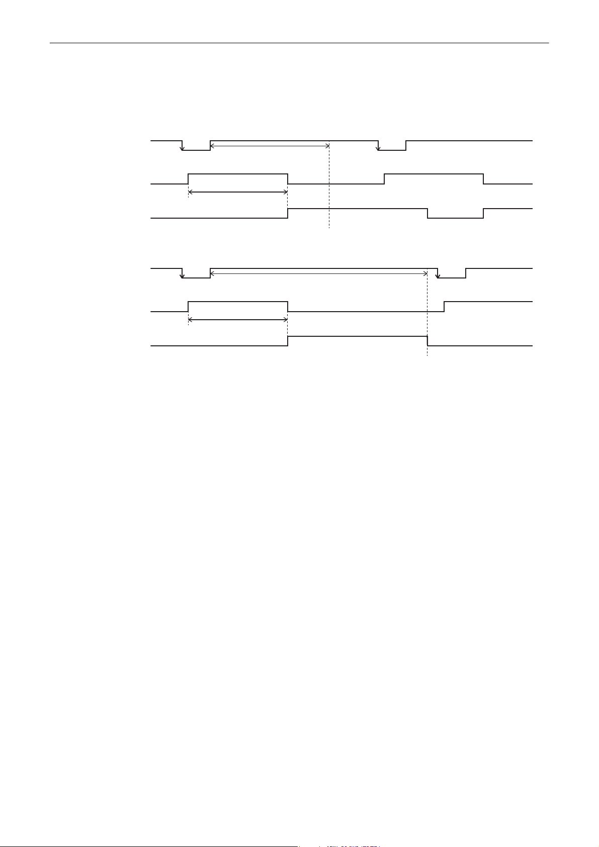
Set TriggerFastMode to False.
Trigger signals can be accepted during the interval that sensor readout signals are asserted.
If the trigger cycle exceeds the maximum value of the frame rate, images are distorted.
When trigger overlap is allowed (when TriggerFastMode is False)
Trigger signal
Exposure signal
Sensor readout signal
(sensor output)
Trigger input inhibited
(frame rate maximum value)
Exposure time
When trigger overlap is inhibited (when TriggerFastMode is True)
Trigger signal
Exposure signal
Sensor readout signal
(sensor output)
Exposure time
Trigger input inhibited
(exposure time + sensor readout time)
23
Page 24
White Balance (Color
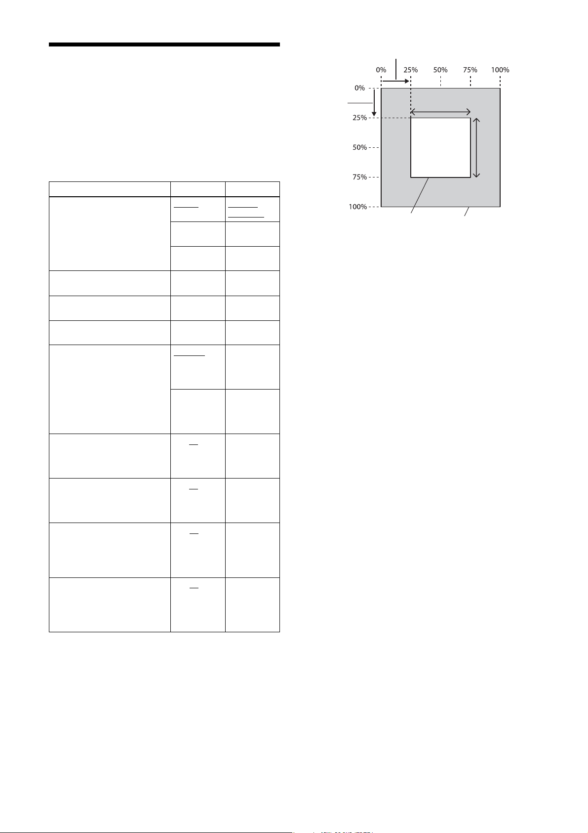
BalanceWhiteAutoAreaOsetX
Camera Only)
The white balance can be automatically adjusted by
executing the BalanceWhiteAuto command. The
detection area is set to the screen center by default. The
detection area can also be displayed on the screen. The
detection frame can be changed arbitrarily. For manual
correction, change the GainDigital parameter.
Feature Parameter Setting
BalanceWhiteAuto Off (0)
Once (1) One-push
Continuous
(2)
GainDigitalRed 256 (×1) to
GainDigitalGreen 256 (×1) to
GainDigitalBlue 256 (×1) to
BalanceWhiteHighlight False (0)
BalanceWhiteAutoAreaWidth 1 to 50
BalanceWhiteAutoAreaHeight 1 to 50
BalanceWhiteAutoAreaOffsetX 0 to 25
BalanceWhiteAutoAreaOffsetY 0 to 25
4095
4095
4095
True (1) AWB
to 100 Horizontal
to 100 Vertical size
to 99 Horizontal
to 99 Vertical
Manual
correction
AW B
Continuous
AW B
Red gain
Green gain
Blue gain
AWB
detection
frame is
hidden
detection
frame is
displayed
size of AWB
detection
frame
of AWB
detection
frame
position of
AW B
detection
frame
position of
AW B
detection
frame
BalanceWhiteAutoAreaOsetY
Detection frame area
BalanceWhiteAutoAreaWidth
BalanceWhiteAutoAreaHeight
Output image
24
Page 25
LUT
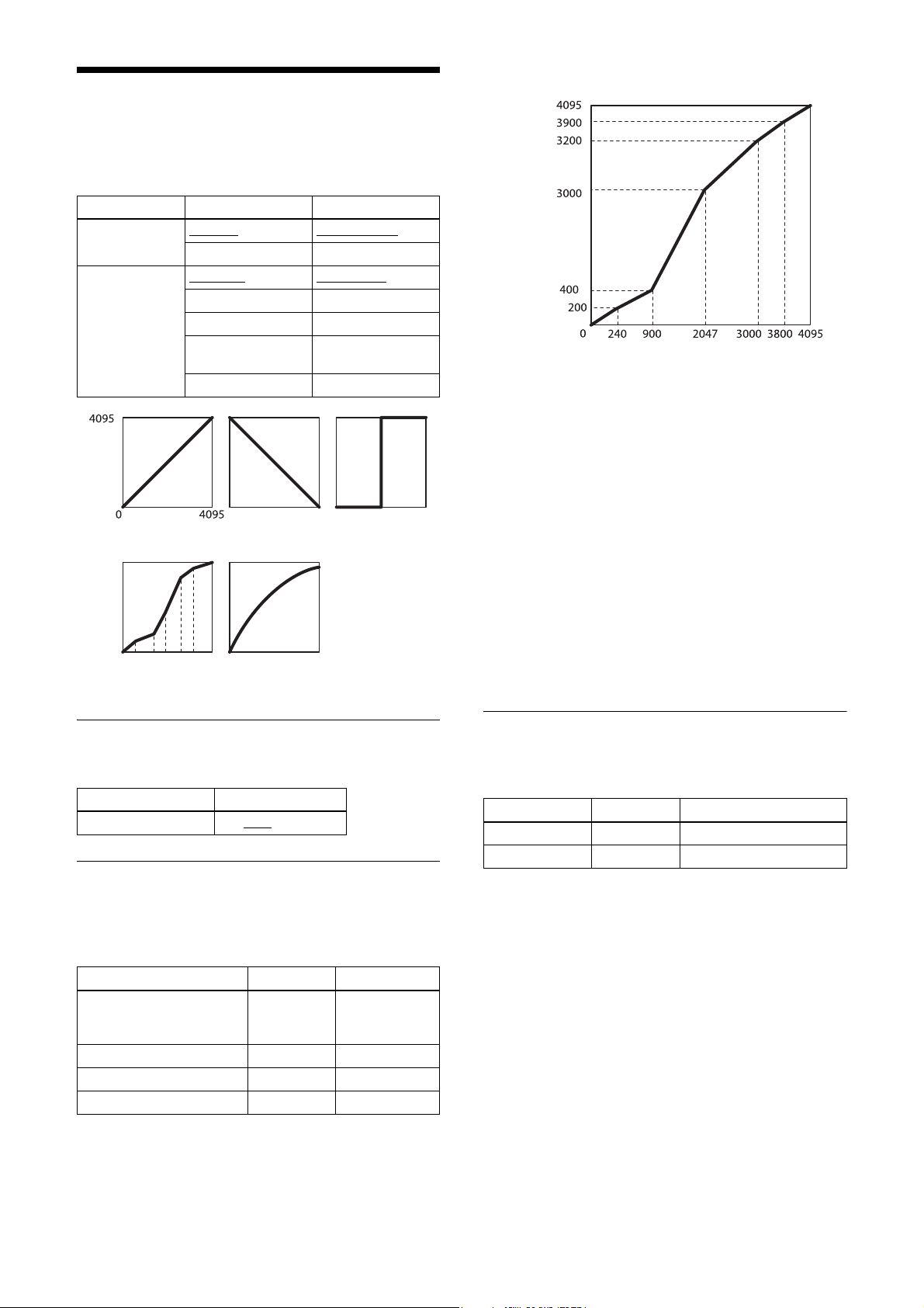
Five types of presets are provided. Specify using a 12-bit
value. Binarization, 5-point interpolation, and arbitrary
setting can be changed.
Setting example:
Feature Parameter Setting
LUTEnable False (0)
True (1) LUT on
LUTFormat Linear (0)
Reverse (1) Reverse
Binarization (2) Binarization
LinearInterpolation
(3)
UserSet (4) Arbitrary setting
Linear (γ=1) Reverse Binarization
5-point
interpolation
LUT off (g=1)
Linear (γ=1)
5-point interpolation
Arbitrary setting
Output
Input
LinearInterpolationIndex = Index1
LinearInterpolationInValue = 240
LinearInterpolationOutValue = 200
LinearInterpolationIndex = Index2
LinearInterpolationInValue = 900
LinearInterpolationOutValue = 400
LinearInterpolationIndex = Index3
LinearInterpolationInValue = 2047
LinearInterpolationOutValue = 3000
LinearInterpolationIndex = Index4
LinearInterpolationInValue = 3000
LinearInterpolationOutValue = 3200
LinearInterpolationIndex = Index5
LinearInterpolationInValue = 3800
LinearInterpolationOutValue = 3900
LinearInterpolationBuild
Binarization
The binarization threshold can be changed.
Feature Parameter
BinarizationThreshold 0 to 2047
to 4095
5-point interpolation
The values of output points 1 through 5 that correspond
to input points 1 through 5 can be changed. Linear
interpolation is performed between interpolation points.
Feature Parameter Setting
LinearInterpolationIndex Index1 to
Index5
LinearInterpolationInValue 0 to 4095 Input
LinearInterpolationOutValue 0 to 4095 Output
LinearInterpolationBuild Build LUT
Select the
interpolation
points
Arbitrary setting
The output values 0 through 4095 that correspond to
input values 0 through 4095 can be changed.
Feature Parameter Setting
LUTIndex 0 to 4095 Input
LUTValue 0 to 4095 Output
Setting example:
LUTIndex = 0
LUTValue = 3
LUTIndex = 1
LUTValue = 10
…
LUTIndex = 4094
LUTValue = 4000
LUTIndex = 4095
LUTValue = 4010
25
Page 26
Saving a LUT
When you change the settings, save them using the
LUTValueSave command.
Feature Parameter Setting
LUTValueSave Save LUT
Color Matrix Conversion (Color Camera Only)
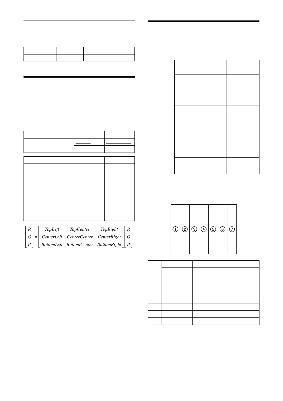
When the color camera is set to BGR8, YCbCr8, or
YCbCr422_8 output, the following color matrix
conversion can be applied. Specify using values between
–8191 and +8191. 256 is ×1.
Feature Parameter Setting
ColorTransformationEnable False (0)
True (1) Conversion on
Feature Parameter Setting
ColorTransformationValue
Selector
ColorTransformationValue –8191 to +256
To pL ef t,
To pC en te r,
TopRight,
CenterLeft,
CenterCenter,
CenterRight,
BottomLeft,
BottomCenter,
BottomRight
to +8191
Conversion off
Matrix position
Gain value
Test Chart Output
For monochrome cameras, a monochrome chart can be
set. For color cameras, a monochrome chart or a color
chart can be set.
Feature Parameter Setting
TestPattern Off (0)
* In a moving test pattern, the position to be drawn moves one pixel at a
time for each frame.
Monochrome chart/color chart
Off
GreyScale (1) Monochrome
chart
ColorBar (2) Color chart
GreyHorizontalRamp (3) Monochrome
GreyVerticalRamp (4) Monochrome
GreyScaleMoving (5) Monochrome
ColorBarMoving (6) Color chart
GreyHorizontalRampMoving
(7)
GreyVerticalRampMoving
(8)
horizontal ramp
vertical ramp
chart (moving)
*
(moving)
Monochrome
horizontal ramp
(moving)
Monochrome
vertical ramp
(moving)
*
*
*
Monochrome Color
Raw/Mono R G B
A 0xF30 0xFFF 0xFFF 0xFFF
B 0xDC0 0xFFF 0xFFF 0
C 0xC80 0 0xFFF 0xFFF
D 0xA00 0 0xFFF 0
E 0x7A0 0xFFF 0 0xFFF
F 0x550 0xFFF 0 0
G 0x340 0 0 0xFFF
26
(12-bit notation)
Page 27
Monochrome horizontal ramp
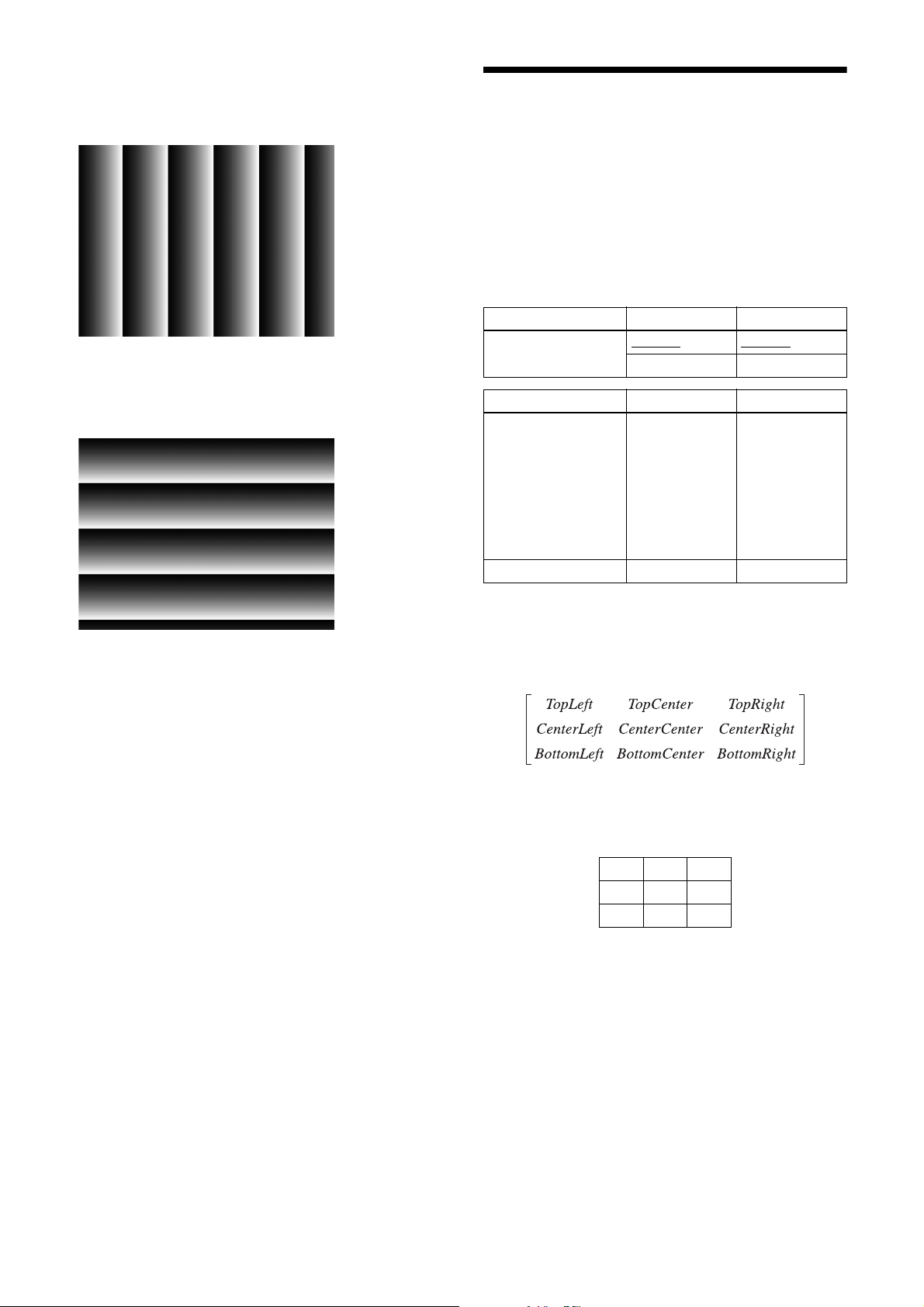
Bar pattern where the image level changes in the
horizontal direction from step 0 by 1 pixel at a time.
Monochrome vertical ramp
Bar pattern where the image level changes in the vertical
direction from step 0 by 1 line at a time.
3 × 3 Filter
Monochrome cameras and color cameras perform 3 × 3
area filtering on RAW output. The brightness of a central
pixel and the eight pixels around it, and the parameter of
each pixel are multiplied and added together, The result
is the brightness of the center pixel. Specify using values
between –8191 and +8191. The parameter 256 is ×1.
Depending on the patterns of coefficients, you can use
filtering to reduce noise, enhance edges, and extract
contours.
Feature Parameter Setting
SpatialFilterEnable False (0)
True (1) Filter on
Feature Parameter Setting
SpatialFilterValue
Selector
SpatialFilterValue –8191 to +8191 Filter coefficient
To pL ef t,
To pC en te r,
TopRight,
CenterLeft,
CenterCenter,
CenterRight,
BottomLeft,
BottomCenter,
BottomRight
Filter off
Matrix position
Select coefficients with SpatialFilterValueSelector and
substitute values with SpatialFilterValue.
The rows with the entered coefficients are represented as
follows.
Within any 9-pixel layout, shown below, where the data
for each pixel is given by Y
result for Y
′
=TopLeft × Y0 + TopCenter × Y1 + TopRight × Y2 +
Y
4
′
is given by the following equation.
4
CenterLeft × Y
CenterRight × Y
Y
0
Y
3
Y
6
+ CenterCenter × Y4 +
3
5
BottomCenter × Y
to Y8, the calculated filter
0
Y1 Y2
Y4 Y5
Y7 Y8
+ BottomLeft × Y6 +
+ BottomRight × Y8
7
27
Page 28
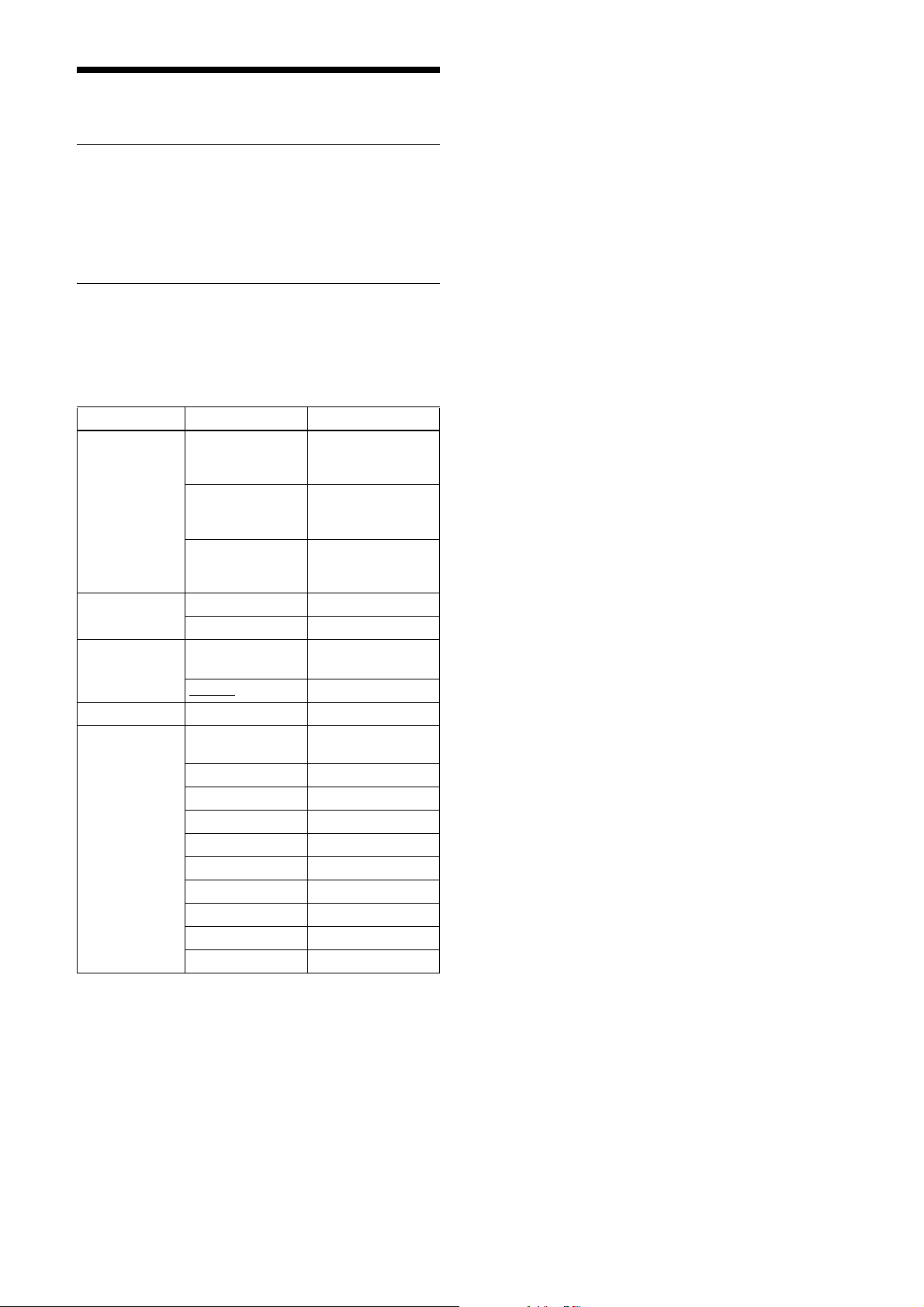
GPIO
GPI
The signal level which is input pin 2 and pin 3 of the DC
power supply input connector can be detected. After
selecting a connector using LineSelector, the signal level
is acquired from LineStatus.
GPO
Various signals can be output from pin 3 and pin 4 of the
DC power supply input connector. Select a connector
using LineSelector, set LineMode to Output, and set
LineSource. The output polarity is set by LineInverter.
Feature Parameter Setting
LineSelector Line1 (0) Pin 2 of the DC
Line2 (1) Pin 3 of the DC
Line3 (2) Pin 4 of the DC
LineMode Input (0) Set to input
Output (1) Set to output
LineInverter False (0) Without output
With output inversion
True (1)
LineStatus Input signal level
LineSource TriggerThrough (0) Trigger through
ExposureActive (1) Exposure signal
StrobeActive (2) Strobe control signal
SensorReadout (3) Sensor readout signal
UserOutput0 (4) User definition 0
UserOutput1 (5) User definition 1
UserOutput2 (6) User definition 2
SignalTrue (7) H level
SignalFalse (8) L level
PulseGenerator (9) Pulse generator signal
power supply input
connector
power supply input
connector
power supply input
connector
inversion
signal
Setting example:
The strobe control signal is output on GPO2 (pin 3 of
the DC power supply input connector, active-High).
LineSelector = Line2
LineMode = Output
LineInverter = False
LineSource = StrobeActive
28
Page 29
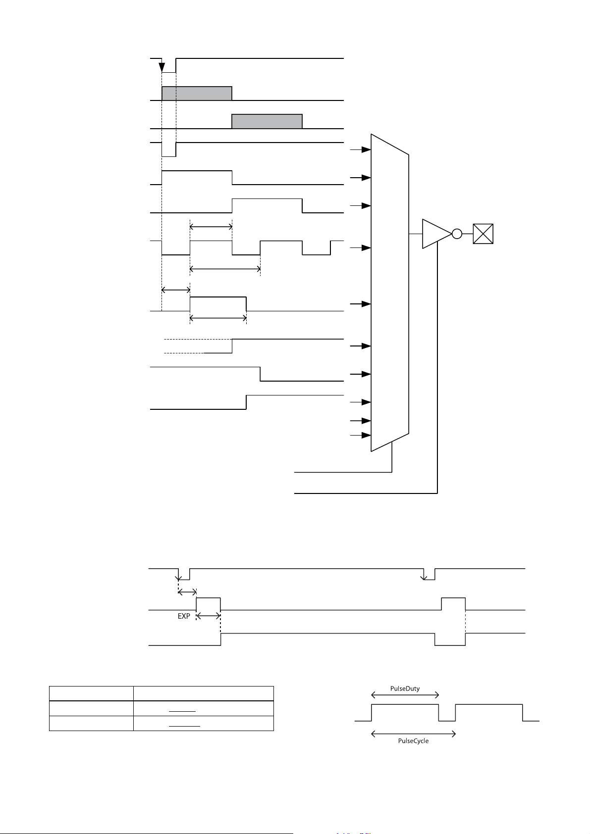
GPO output system diagram (example of GPO1)
Trigger signal
Exposure
Sensor output
Trigger through signal
Exposure signal
Sensor readout signal
Pulse output
StrobeActiveDelay
Strobe control signal
StrobeActiveTime
GPO2
GPO3
User definition 0
1
0
User definition 1
User definition 2
1
0
LineSource
LineInverter
Sensor readout (Sensor output)
When exposure finishes, this signal indicates that the image sensor is in the image output sequence. Output is available
from the GPO2/3 connectors. The sensor readout signal is asserted before the optical black (OB) and the effective pixel
area are output.
Trigger signal
Trigger latency
Exposure signal
Sensor readout signal
(Sensor output)
Pulse output
A pulse waveform can be output from the GPO2/3 connector. Available range is 0.5 Hz to 100 kHz.
Feature Parameter
PulseDuty 1 to 500000
PulseCycle 10 to 1000000
to 2000000 [µs]
to 2000000 [µs]
29
Page 30
Status LED
The status indicated by the LED (lit, blinking, not lit) on
the rear panel is as follows: You can change whether
LEDs are lit or not with a user command.
Lit Power supply is applied. Ready for operation.
Blinking Power supply is applied. Connected by USB 2.0.
Off Power supply is not available, or the power
supply is connected but not turned on. Or the
LED was turned off by a user command.
Feature Parameter Setting
LEDMode False (0) Off
Lit
True (1)
2
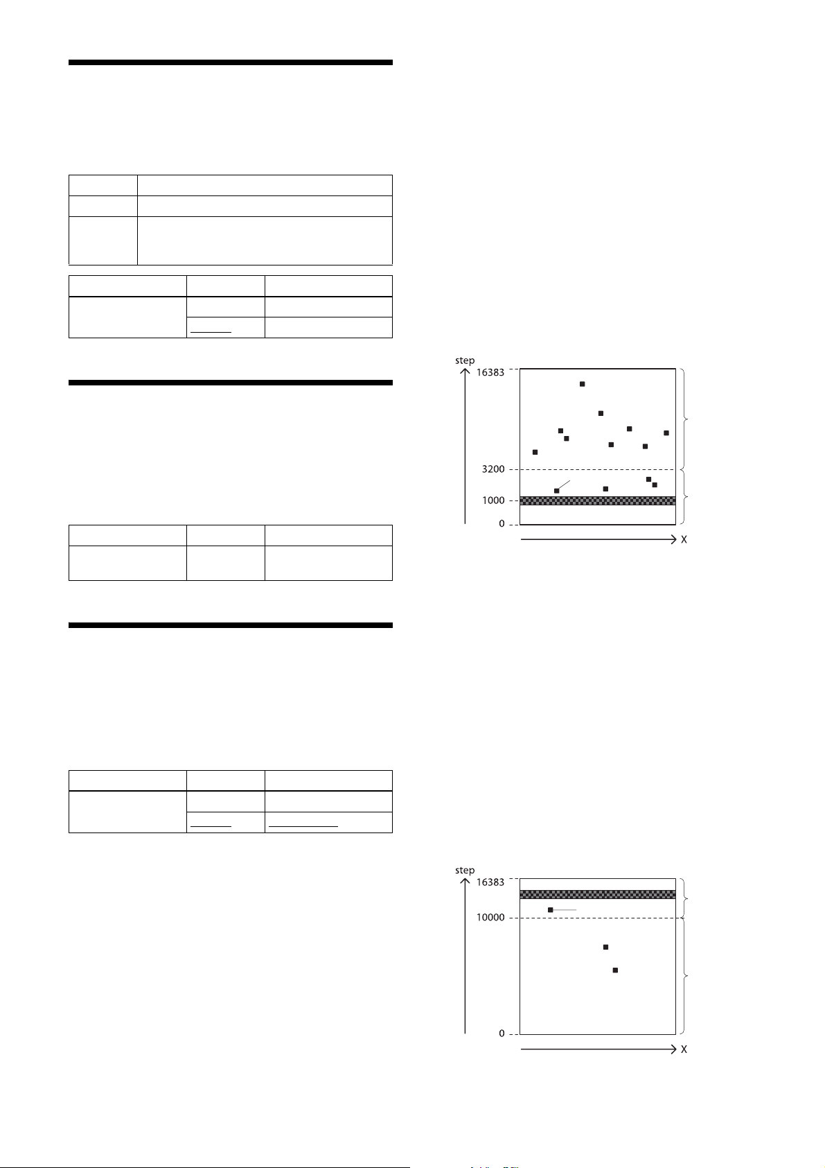
Set the threshold in units of 14 bits. White defect
points are detected when this level is exceeded.
Below is an example for 3200 steps/14 bits. Pixels in
the range 3200 to 16383 are detected.
> DefectThreshold = 3200
3
Execute white defect point detection. Detection
takes four times the EXP time setting. The output
levels for the same X coordinate are shown below.
The display is uniformly black around step 1000 for
an all-black image, but defect pixels (at high levels)
are present in some locations. All pixels whose level
exceed the step 3200 threshold set in step 2 are
detected.
> DefectDetectionMode = DetectWhitePixels
Temperature Readout Function
The camera’s internal temperature can be read from a
temperature sensor mounted on the module board. Its
accuracy is ±2 °C. Use this value as a general guide.
Feature Parameter Setting
DeviceTemperature Temperature sensor
value
Defect Correction
This function corrects for white defect pixels and black
defect pixels. A correction is applied for defective pixels
by interpolating from the peripheral pixels surrounding
the detected defect. The factory setting and user setting
can be selected.
Feature Parameter Setting
DefectCorrection False (0) Correction off
Correction on
True (1)
Defect correction setup procedure
1
Set conditions in which white defect points are
easier to detect. Below is an example in which the
gain is 18 dB and the shutter is 1 second. Prevent as
much light as possible from entering by blocking
light.
> Gain = 18
> ExposureTime = 1000000
Pixels that
are detected
Defect pixel
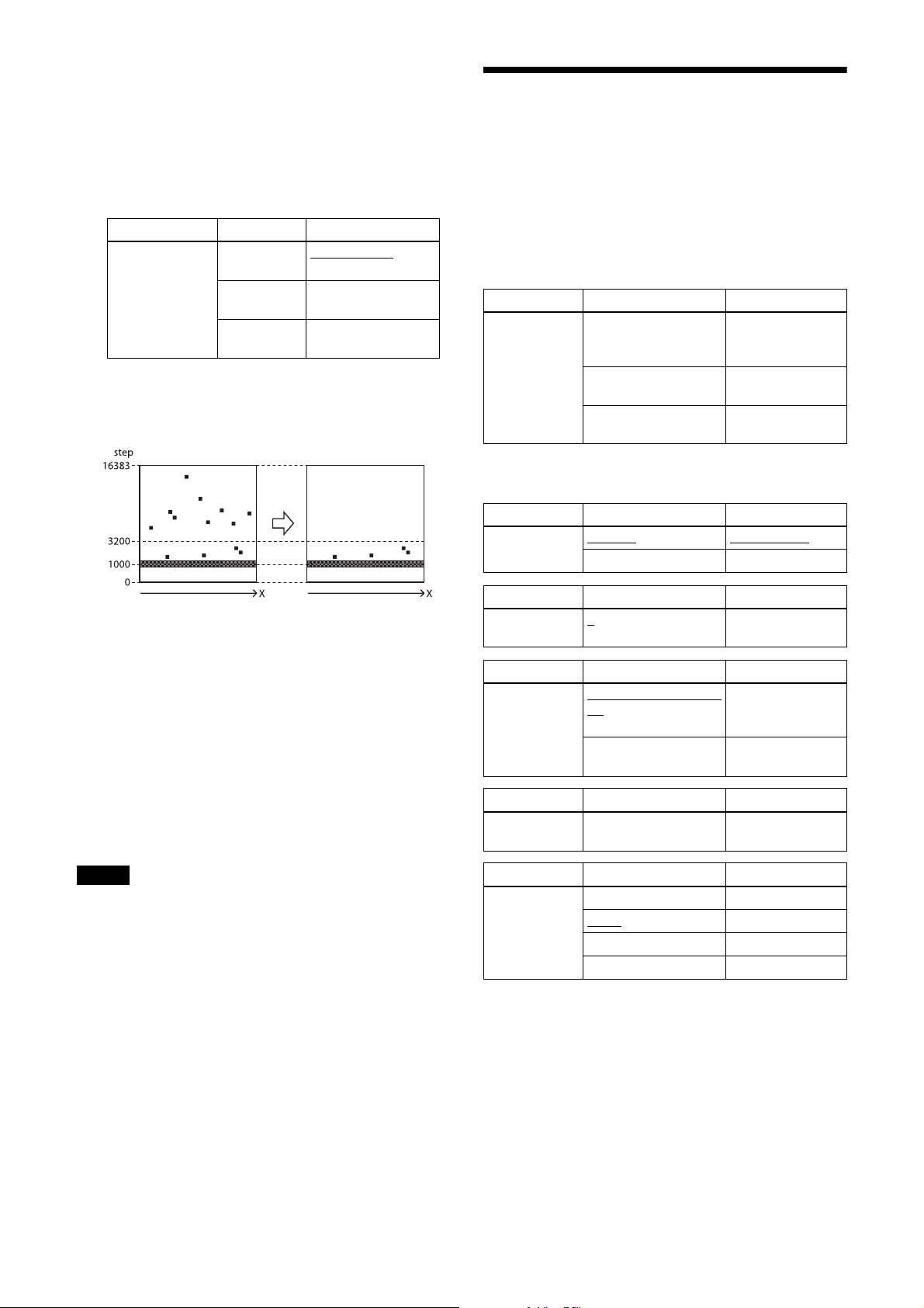
4
Execute black defect point detection. Like the white
defect point detection, set the image pickup
conditions and the threshold in units of 14 bits.
Below is an example for 10000 steps/14 bits. Pixels
from step 0 to step 10000 are detected. If not setting
black defect points, you can skip this step.
> DefectThreshold = 10000
> DefectDetectionMode = DetectBlackPixels
Read the status to determine whether the detection is
finished.
> DefectDetectionMode (readout)
DetectBlackPixels (executing)
Off (exit)
The value Off is returned when finished.
Defect pixel
Pixels that
are not
detected
Pixels that
are not
detected
Pixels that
are
detected
30
Page 31
5
Select the data for applying defect correction. To
apply the pixels detected in steps 3 and 4, select
DefectPatternDetected. To apply factory settings,
select DefectPatternFactory. To apply values that
have been saved, select DefectPatternUser.
> DefectPatternLoad = DefectPatternDetected
Feature Parameter Setting
DefectPatternLoad
6
Turn on defect correction.
DefectPattern
Factory (0)
DefectPattern
User (1)
DefectPattern
Detected (2)
Factory setting
User setting
Data detected using
DefectDetectionMode
> DefectCorrection = True
Shading Correction
Depending on the characteristics of the lens, shading
caused by a drop in the amount of light around the lens,
or light source variation, can be corrected. You can save
up to 31 user-defined patterns.
There are two shading correction modes. In peak
detection mode, you can adjust for the brightest level of
the screen. In average detection mode, you can adjust for
the average value of brightness for the whole screen.
Feature Parameter Setting
ShadingDetection
Mode
Set the camera mode to NORMAL. For details, see
“Camera Mode” (page 12).
Feature Parameter Setting
Shading
Correction
ShadingDetectionOff
(0)
ShadingDetectionBy
PeakValue (1)
ShadingDetectionBy
AverageValue (2)
False (0)
True (1) Correction on
Correction off
Check that the
detection is
completed
Start detection
(peak detection)
Start detection
(average detection)
7
Save the settings. To repeat defect detection without
saving, repeat steps 1 to 6.
> DefectPatternSave = True
Read the status to determine whether the save
operation is finished.
> DefectPatternSave (readout)
True (executing)
False (exit)
The value False is returned when finished.
Note
The upper limit of defect detection points is 2047 for
white and black defect points combined. Correction
cannot be performed over the upper limit. The detected
defect points can be confirmed using
DefectDetectionResult. If the upper limit is exceeded,
defect detection will fail or abnormal defect detection
will occur, and the value of DefectDetectionResult will
be set to –1. Defect detection should be performed with
the camera mode set to NORMAL. For details, see
“Camera Mode” (page 12).
Feature Parameter Setting
ShadingPattern
Select
Feature Parameter Setting
ShadingPattern
Save
Feature Parameter Setting
ShadingPattern
Load
Feature Parameter Setting
ShadingDetect
Color
to 30 Shading pattern
0
ShadingPatternSaveOff
(0)
ShadingPatternSaveOn
(1)
Red Red
Green
Green
Blue Blue
Luminance Luminance
selection
Check that shading
pattern saving is
finished
Start shading
pattern saving
Load shading
pattern
31
Page 32
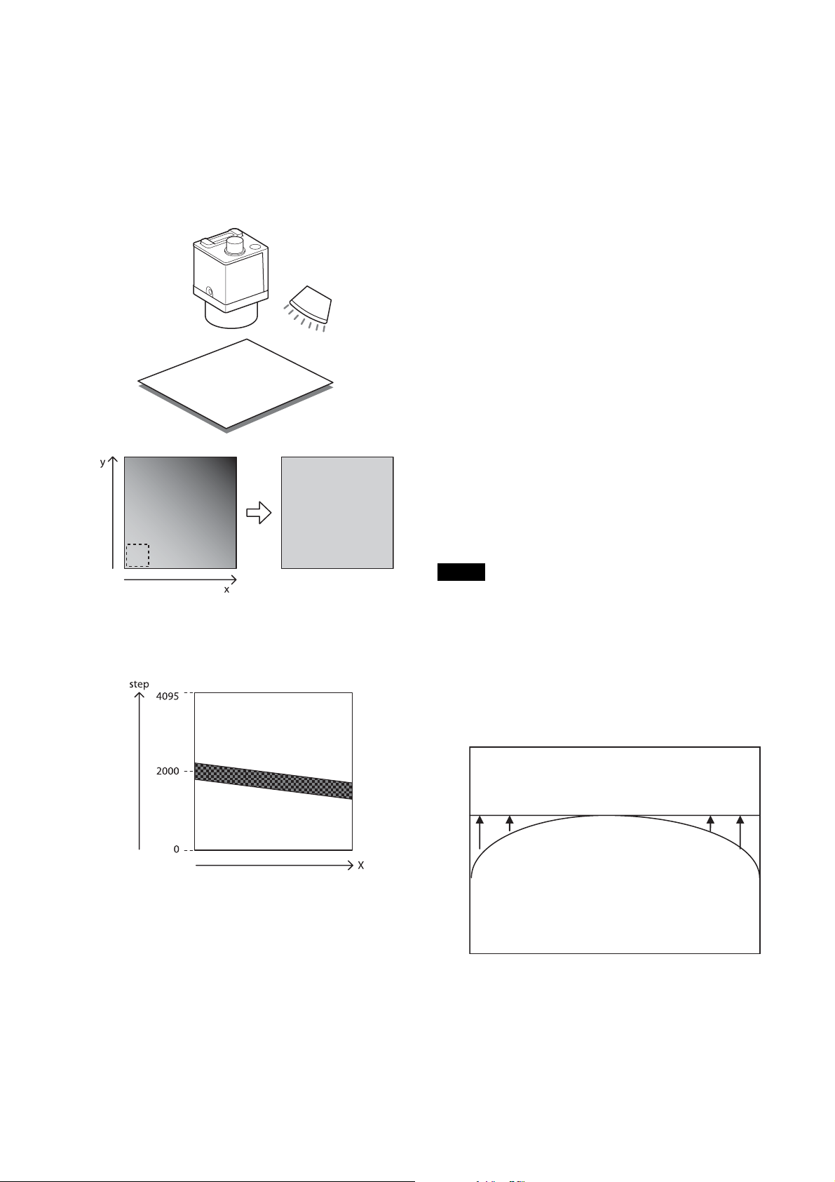
Shading detection setup procedure
1
As shown in the figure below, assume an
environment in which the brightness is not uniform
due to an uneven light source. In peak detection
mode, shading correction adjusts the brightness
level as the target level.
Fix the lens and lighting conditions.
> ShadingDetectionMode (readout)
ShadingDetectionByPeakValue or
ShadingDetectionByAverageValue (executing)
ShadingDetectionOff (exit)
The value ShadingDetectionOff is returned when
finished.
4
Check the shading correction effect.
Camera
Light source
A colorless and uniform
photographic subject
Brightest area
= target level
2
Adjust the exposure time and other parameters so
that the target level is about 50%. On color cameras,
adjust the white balance.
Correction
> ShadingPatternCheck
5
Save the shading pattern.
>ShadingPatternSelect = 0
> ShadingPatternSave = ShadingPatternSaveOn
Read the status to determine whether the save
operation is finished.
> ShadingPatternSave (readout)
ShadingPatternSaveOn (executing)
ShadingPatternSaveOff (exit)
The value ShadingPatternSaveOff is returned when
finished.
6
Read out the saved pattern.
>ShadingPatternSelect = 0
> ShadingPatternLoad
Note
Perform the shading detection with the trigger mode set
to off.
Peak detection mode
ShadingDetectionMode =
ShadingDetectionByPeakValue
3
Performs shading detection by selected mode.
> ShadingDetectionMode =
ShadingDetectionByPeakValue or
ShadingDetectionByAverageValue
Read the status to determine whether the calculation
is finished.
The subject appears brighter.
Average value detection mode
ShadingDetectionMode =
ShadingDetectionByAverageValue
32
Page 33
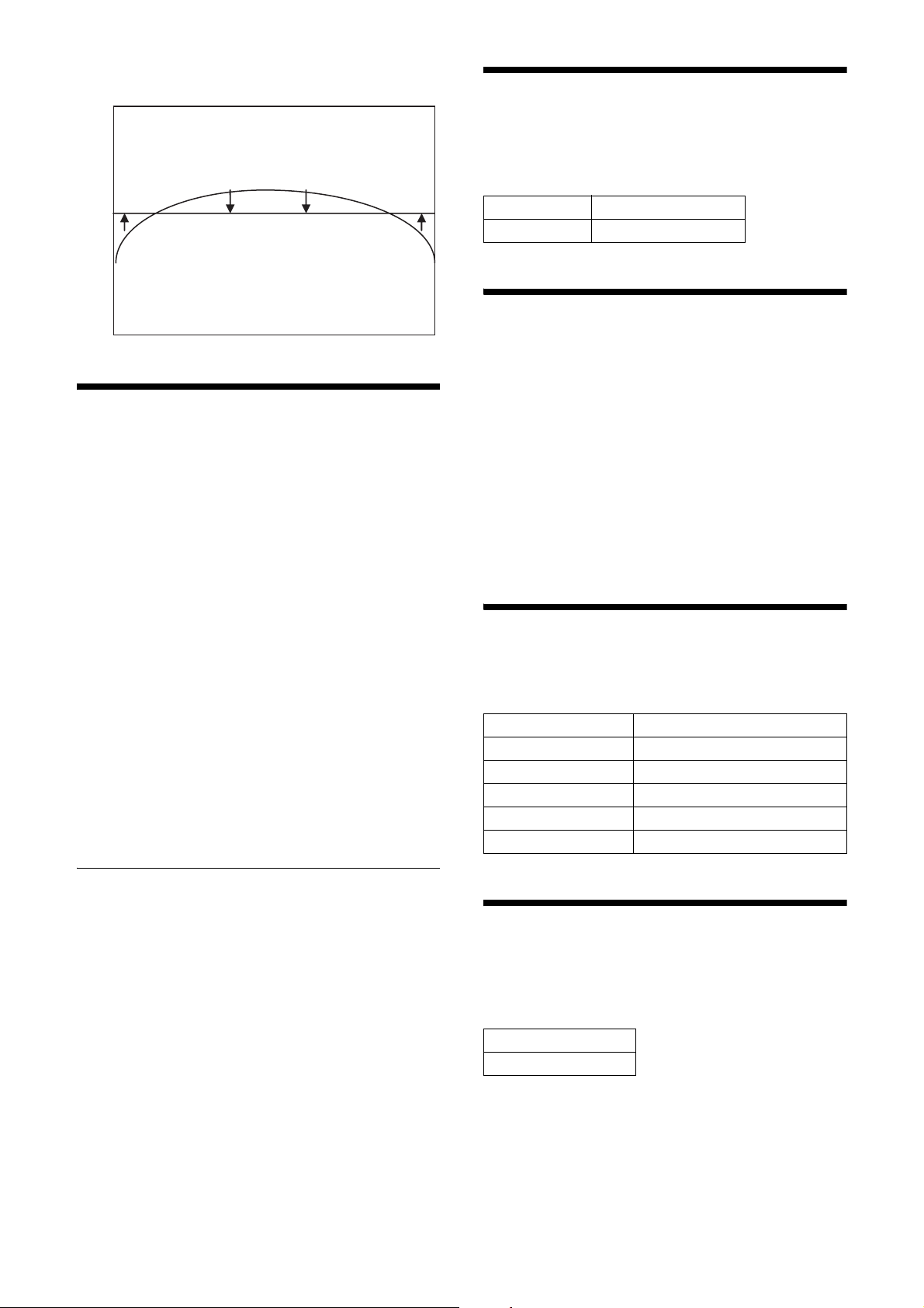
Darker areas of the subject may appear darker.
User Set
The main configuration values can be saved to channels
1 to 16 using UserSet. For details about items that are
saved, see “Command List” (page 34).
Factory settings are saved to channel 0, and cannot be
overwritten.
Setting example 1:
Shutter is 3 ms, Gain is 3 dB, Pulse signal is output to
GPO3 connector (this setting is saved to channel 1).
ExposureTime = 3000
Gain = 3
LineSelector = Line3
LineMode = Output
LineSource = PulseGenerator
UserSetSelector = UserSet1
UserSetSave
Setting example 2:
The user set saved in the channel 2 is loaded.
UserSetSelector = UserSet2
UserSetLoad
User ID
User IDs are unique names that can be assigned to
cameras. A string that is 64 characters long can be
assigned.
Feature Parameter
DeviceUserID Arbitrary 64 characters
Saving and Startup
The startup settings can be determined using
UserSetDefault. This is also used to check which user
set settings are currently being used.
Usage example:
Startup with the setting saved in user set channel 3.
UserSetDefault = UserSet3
(Restart or DeviceReset command)
Check which user set settings are the current settings.
Read UserSetDefault
Camera Information
The model name of a camera and its firmware
information can be read out.
Feature Parameter
DeviceVendorName Manufacturer (Sony)
DeviceModelName Model name
DeviceVersion Device version
DeviceSerialNumber Serial number
DeviceManufacturerInfo Data for manufacturer service
User set memory
A number is assigned to one item saved in each user set
channel. Signed 32-bit numbers are assigned to slots 0 to
15.
Restarting
The camera reboots 3 seconds after the reset command
is sent. Exit the application software during this short
interval.
Feature
DeviceReset
33
Page 34
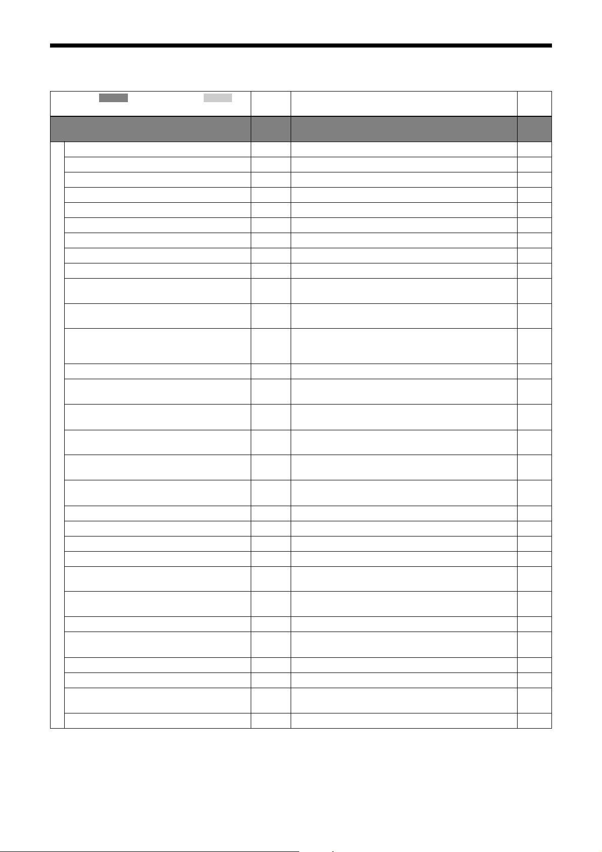
Command List
Category ( ) / Sub category ( )
Feature
DeviceControl RO Category for device information and control
DeviceType RO Returns the device type. –
DeviceScanType RO Scan type of the sensor of the device. –
DeviceVendorName RO Name of the manufacturer of the device (Sony). 33
DeviceModelName RO Model name of the device. 33
DeviceManufacturerInfo RO Manufacturer information about the device. 33
DeviceVersion RO Version of the device. 33
DeviceFirmwareVersion RO Version of the firmware in the device. –
DeviceSerialNumber RO Serial number of the device. 33
DeviceUserID RW User-programmable device identifier. 33
DeviceSFNCVersionMajor RO Major version of the Standard Features Naming Convention
DeviceSFNCVersionMinor RO Minor version of the Standard Features Naming Convention
DeviceSFNCVersionSubMinor RO Sub minor version of the Standard Features Naming
DeviceManifestEntrySelector RW Selects the manifest entry to reference. –
DeviceManifestXMLMajorVersion RO Indicates the major version number of the GenICam XML
DeviceManifestXMLMinorVersion RO Indicates the minor version number of the GenICam XML
DeviceManifestXMLSubMinorVersion RO Indicates the sub minor version number of the GenICam
DeviceManifestSchemaMajorVersion RO Indicates the major version number of the schema file of the
DeviceManifestSchemaMinorVersion RO Indicates the minor version number of the schema file of the
DeviceTLType RO Transport Layer type of the device. –
DeviceTLVersionMajor RO Major version of the Transport Layer of the device. –
DeviceTLVersionMinor RO Minor version of the Transport Layer of the device. –
DeviceTLVersionSubMinor RO Sub minor version of the Transport Layer of the device. –
DeviceGenCPVersionMajor RO Major version of the GenCP protocol supported by the
DeviceGenCPVersionMinor RO Minor version of the GenCP protocol supported by the
DeviceConnectionSelector RW Selects which connection of the device to control. –
DeviceConnectionSpeed RO Indicates the speed of transmission of the specified
DeviceConnectionStatus RO Indicates the status of the specified connection. –
DeviceLinkSelector RW Selects which link of the device to control. –
DeviceLinkSpeed RO Indicates the speed of transmission negotiated on the
DeviceLinkThroughputLimitMode RW Controls if DeviceLinkThroughputLimit is active. –
*1 RO: Read only, WO: Write only, RW: Read/Write
*2 Color cameras are RO.
*3 Target models: Color cameras
*4 Enabled when color camera is set to BGR8, YCbCr8, or YCbCr422_8.
*5 Target camera mode: NORMAL
Read/
Write
Description See
*1
features.
that was used to create the device’s GenICam XML.
that was used to create the device’s GenICam XML.
Convention that was used to create the device’s GenICam
XML.
file of the selected manifest entry.
file of the selected manifest entry.
XML file of the selected manifest entry.
selected manifest entry.
selected manifest entry.
device.
device.
connection.
specified link.
page
–
–
–
–
–
–
–
–
–
–
–
–
–
34
Page 35
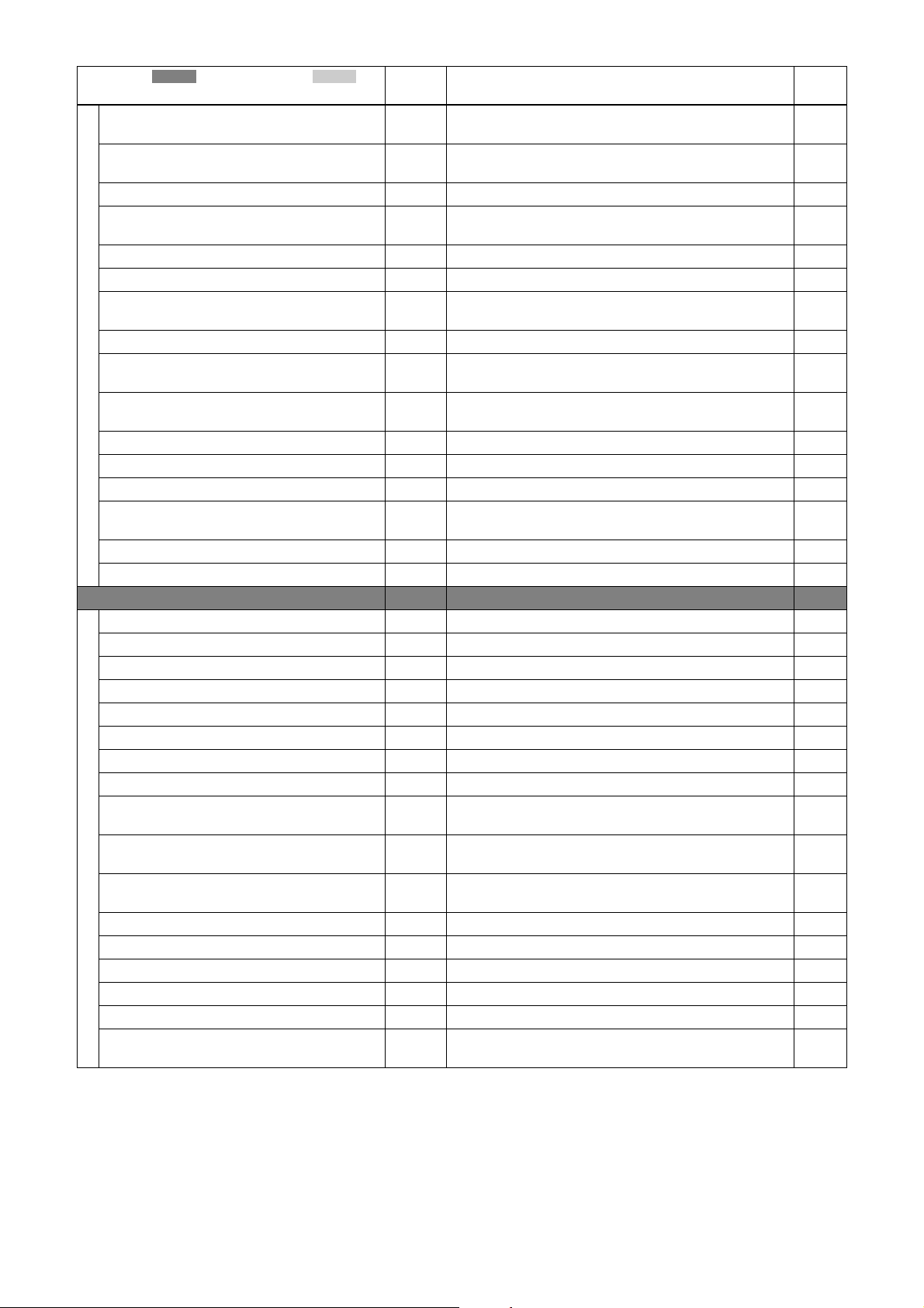
Category ( ) / Sub category ( )
Feature
Read/
Write
Description See
*1
DeviceLinkThroughputLimit RW Limits the maximum bandwidth of the data that will be
streamed out by the device on the selected link.
DeviceLinkConnectionCount RO Returns the number of physical connection of the device
used by a particular link.
DeviceLinkCommandTimeout RO Indicates the command timeout of the specified link. –
DeviceStreamChannelCount RO Indicates the number of streaming channels supported by the
device.
DeviceStreamChannelSelector RW Selects the stream channel to control. –
DeviceStreamChannelType RO Returns the type of the stream channel. –
DeviceStreamChannelLink RW Index of device’s link to use for streaming the specified
stream channel.
DeviceStreamChannelEndianness RO Endianness of multi-byte pixel data for this stream. –
DeviceEventChannelCount RO Indicates the number of event channels supported by the
device.
DeviceCharacterSet RO Character set used by the strings of the device’s bootstrap
registers.
DeviceReset WO Resets the device to its power up state. 33
DeviceRegistersEndianness RO Endianness of the registers of the device. –
DeviceTemperature RO Device temperature in degrees Celsius (°C). 30
TimestampLatch WO Latches the current timestamp counter into
TimestampLatchValue.
TimestampLatchValue RO Returns the latched value of the timestamp counter. –
FactoryDefault RW Restores all settings to the factory default. –
ImageFormatControl RO Category for image format control features. –
SensorWidth RO Effective width of the sensor (in pixels). –
SensorHeight RO Effective height of the sensor (in pixels). –
SensorUnitCellSizeH RO Horizontal pixel cell size. –
SensorUnitCellSizeV RO Vertical pixel cell size. –
WidthMax RO Maximum width of the image (in pixels). –
HeightMax RO Maximum height of the image (in pixels). –
Width RW Width of the image provided by the device (in pixels). 11
Height RW Height of the image provided by the device (in pixels). 11
OffsetX RW Horizontal offset from the origin to the region of interest (in
pixels).
OffsetY RW Vertical offset from the origin to the region of interest (in
pixels).
*2
BinningHorizontal RW
Number of horizontal photo-sensitive cells to combine
together.
*2
BinningVertical RW
Number of vertical photo-sensitive cells to combine together. 11
ReverseX RW Flip horizontally the image sent by the device. 15
ReverseY RW Flip vertically the image sent by the device. 15
PixelFormat RW Format of the pixels provided by the device. 14
PixelSize RO Total size in bits of a pixel of the image. –
TestPattern RW Selects the type of test pattern that is generated by the device
as the image source.
*1 RO: Read only, WO: Write only, RW: Read/Write
*2 Color cameras are RO.
*3 Target models: Color cameras
*4 Enabled when color camera is set to BGR8, YCbCr8, or YCbCr422_8.
*5 Target camera mode: NORMAL
page
–
–
–
–
–
–
–
11
11
11
26
35
Page 36
Category ( ) / Sub category ( )
Feature
Read/
Write
Description See
*1
AcquisitionControl RO Category for the acquisition and trigger control
features.
AcquisitionMode RW Sets the acquisition mode of the device. –
AcquisitionAbort RW Aborts the acquisition immediately. –
AcquisitionFrameCount RW Number of frames to acquire in MultiFrame acquisition
mode.
AcquisitionFrameRateAuto RW Automatically controls the maximum rate (in Hz) at which
the line in a frame is captured when TriggerMode is Off.
AcquisitionFrameRate RW Controls the rate (in Hz) at which the line in a frame is
captured when TriggerMode is Off for the frame trigger.
AcquisitionFrameRateActual RO Indicates the actual frame rate (in Hz). 21
TriggerMode RW Controls if the selected trigger is active. 17
TriggerSoftware RW Generates an internal trigger. 17
TriggerSource RW Specifies the internal signal or physical input line to use as
the trigger source.
TriggerActivation RW Specifies the activation mode of the trigger. 8
TriggerDelay RW Specifies the delay in microseconds to apply after the trigger
reception before activating it.
TriggerInhibit RW Specifies the activation of the trigger. 19
TriggerFastMode RW Sets the trigger mode of the image sensor. 22
TriggerCounter RO Gets the count of trigger. 20
TriggerCounterReset WO Resets the trigger counter. 20
TriggerAcceptanceRangeEnable RW Controls if the trigger acceptance range is enabled. 20
TriggerAcceptanceRangeLowerLimit RW Sets the lower limit of trigger acceptance range. 20
FrameCounter RO Gets the count of frames. 22
FrameCounterReset WO Resets the frame counter. 22
ExposureMode RW Sets the operation mode of the exposure. 17
ExposureTime RW Sets the exposure time when ExposureMode is Timed and
ExposureAuto is Off.
ExposureAuto RW Sets the automatic exposure mode when ExposureMode is
Time d.
ExposureAutoSpeed RW Sets the automatic exposure speed. 16
ExposureAutoLowerLimit RW Sets the lower limit for Exposure Auto mode. 16
ExposureAutoUpperLimit RW Sets the upper limit for Exposure Auto mode. 16
Exposure2Time RW Sets the second exposure time for burst trigger mode. 18
Exposure2Ratio RW Sets the exposure time ratio for burst trigger mode. 18
BurstFrameCount RW Sets the number of frames to acquire in burst trigger mode. 18
BurstTriggerMode RW Sets burst trigger mode. 18
BurstTriggerPeriod RW Sets the burst period type. 18
BurstForceStop WO Stops the acquisition of the device at the end of the current
frame.
AnalogControl RO Category that contains the analog control features. –
GainSelector RW Selects which gain is controlled by the various gain features. –
Gain RW Controls the selected gain as an absolute physical value (in
dB).
GainAnalog RW Controls the selected gain as an absolute physical value. 15
*3
GainDigitalRed
*1 RO: Read only, WO: Write only, RW: Read/Write
*2 Color cameras are RO.
*3 Target models: Color cameras
*4 Enabled when color camera is set to BGR8, YCbCr8, or YCbCr422_8.
*5 Target camera mode: NORMAL
RW Digital gain for the red channel. 24
page
–
–
21
21
17
20
16
16
18
15
36
Page 37
Category ( ) / Sub category ( )
Feature
GainDigitalGreen
GainDigitalBlue
*3
RW Digital gain for the green channel. 24
*3
RW Digital gain for the blue channel. 24
Read/
Write
Description See
*1
GainAuto RW Sets automatic gain control (AGC) mode. 15
GainAutoLevel RW Sets the target level for Gain Auto and Exposure Auto mode. 15
GainAutoSpeed RW Sets the automatic gain speed. 15
GainAutoLowerLimit RW Sets the lower limit for the gain auto control. 15
GainAutoUpperLimit RW Sets the upper limit for the gain auto control. 15
BlackLevel RW Controls the analog black level as an absolute physical value. –
*3
BalanceWhiteAuto
RW Controls the mode for automatic white balancing between
the color channels.
SpatialFilterEnable RW Activates the 3×3 spatial filter. 27
SpatialFilterValueSelector RW Selects which physical line (or pin) of the external device
connector to control.
SpatialFilterValue RW Controls the selected parameter for 3×3 spatial filter. 256
means ×1.0.
ColorTransformationEnable
ColorTransformationValueSelector
*4
RW Activates the color transformation filter. 26
*4
RW Selects which physical line (or pin) of the external device
connector to control.
ColorTransformationValue
*4
RW Controls the selected parameter for color transformation
filter. 256 means ×1.0.
LUTControl RO Category that includes LUT control features. –
LUTEnable RW Activates the selected LUT. 25
LUTFormat RW Selects which LUT format is controlled among the various
LUT formats.
BinarizationThreshold RW Controls the binarization threshold (12 bits). 25
LinearInterpolationIndex RW Selects the index point to build a linear interpolation LUT. 25
LinearInterpolationInValue RW Specifies the In value of the point selected by
LinearInterpolationIndex.
LinearInterpolationOutValue RW Specifies the Out value of the point selected by
LinearInterpolationIndex.
LinearInterpolationBuild WO Builds a linear interpolation LUT. 25
LUTIndex RW Controls the index (offset) of the coefficient to access in the
selected LUT.
LUTValue RW Returns the value at entry LUTIndex of the LUT selected by
LUTSelector.
LUTValueSave WO Saves the value of the LUT to flash memory. 26
DigitalIOControl RO Category that contains the digital input and output
control features.
LineSelector RW Selects the physical line (or pin) of the external device
connector or the virtual line of the Transport Layer to
configure.
LineMode RW Controls if the physical line is used to input or output a
signal.
LineSource RW Selects which internal acquisition or I/O source signal to
output on the selected line.
LineInverter RW Controls the inversion of the signal of the selected input or
output line.
LineStatus RO Returns the current status of the selected input or output line. 28
*1 RO: Read only, WO: Write only, RW: Read/Write
*2 Color cameras are RO.
*3 Target models: Color cameras
*4 Enabled when color camera is set to BGR8, YCbCr8, or YCbCr422_8.
*5 Target camera mode: NORMAL
page
24
27
27
26
26
25
25
25
25
25
–
28
28
28
28
37
Page 38
Category ( ) / Sub category ( )
Feature
Read/
Write
Description See
*1
StrobeControl RO Controls strobe signal output. –
StrobeActiveTime2 RW Sets the strobe active time (in µs) for line 2. –
StrobeActiveDelay2 RW Specifies the delay (in µs) to apply after StrobeActive before
activating it.
StrobeActiveTime3 RW Sets the strobe active time (in µs) for line 3. –
StrobeActiveDelay3 RW Specifies the delay (in µs) to apply after StrobeActive before
activating it.
PulseWidthControl RO Controls the pulse output. –
PulseCycle RW Controls the pulse cycle. 29
PulseDuty RW Controls the pulse duty. 29
UserOutputControl RO Controls the user output. –
UserOutputSelector RW Selects which bit of the UserOutput register will be set by
UserOutputValue.
UserOutputValue RW Sets the value of the bit selected by UserOutputSelector. –
UserOutput0 RW Controls the value of User Output 0. –
UserOutput1 RW Controls the value of User Output 1. –
UserOutput2 RW Controls the value of User Output 2. –
EventControl RO Category that contains event control features. –
EventSelector RW Selects which event to signal to the host application. –
EventNotification RW Activates or deactivates the notification to the host
application of the occurrence of the selected event.
EventAcquisitionStartData RO Category that contains all the data features related to the
acquisition start event.
EventAcquisitionStart RO Returns the unique identifier of the acquisition start type of
the event.
EventAcquisitionStartTimestamp RO Returns the timestamp of the acquisition start event. –
EventAcquisitionStartFrameID RO Returns the unique identifier of the frame (or image) that
generated the acquisition start event.
EventAcquisitionEndData RO Category that contains all the data features related to the
acquisition end event.
EventAcquisitionEnd RO Returns the unique identifier of the acquisition end type of
the event.
EventAcquisitionEndTimestamp RO Returns the timestamp of the acquisition end event. –
EventAcquisitionEndFrameID RO Returns the unique identifier of the frame (or image) that
generated the acquisition end event.
EventAcquisitionErrorData RO Category that contains all the data features related to the
acquisition error event.
EventAcquisitionError RO Returns the unique identifier of the acquisition error type of
the event.
EventAcquisitionErrorTimestamp RO Returns the timestamp of the acquisition error event. –
EventAcquisitionErrorFrameID RO Returns the unique identifier of the frame (or image) that
generated the acquisition error event.
EventErrorData RO Category that contains all the data features related to the
error event.
EventError RO Returns the unique identifier of the error type of the event. –
EventErrorTimestamp RO Returns the timestamp of the error event. –
EventErrorFrameID RO Returns the unique identifier of the frame (or image) that
generated the error event, if applicable.
EventErrorCode RO Returns an error code for the error(s) that happened. –
*1 RO: Read only, WO: Write only, RW: Read/Write
*2 Color cameras are RO.
*3 Target models: Color cameras
*4 Enabled when color camera is set to BGR8, YCbCr8, or YCbCr422_8.
*5 Target camera mode: NORMAL
page
–
–
–
–
–
–
–
–
–
–
–
–
–
–
–
38
Page 39
Category ( ) / Sub category ( )
Feature
Read/
Write
Description See
*1
EventTestData RO Category that contains all the data features related to the
event test generated using the TestEventGenerate command.
EventTest RO Returns the unique identifier of the event test type of event
generated using the TestEventGenerate command.
EventTestTimestamp RO Returns the timestamp of the event test event. –
UserSetControl RO Category that contains the User Set control
features.
UserSetSelector RW Selects the feature User Set to load. 33
UserSetLoad RW Loads the User Set specified by UserSetSelector to the
device and makes it active.
UserSetSave RW Saves the User Set specified by UserSetSelector to the non-
volatile memory of the device.
UserSetDefault RW Selects the feature User Set to load and make active by
default when the device is reset.
UsersetMemoryIndex RW Provides the index (offset) of the user-programmable
identifier to access in the UserMemory.
UsersetMemoryValue RW Represents the value found at entry UserMemoryIndex. –
ChunkDataControl RO Category that contains the Chunk Data control
features.
ChunkModeActive RW Activates the inclusion of chunk data in the payload of the
image.
ChunkSelector RW Selects which chunk to enable or control. –
ChunkEnable RW Enables the inclusion of the selected chunk data in the
payload of the image.
ChunkImage RO Returns the entire image data included in the payload. –
ChunkOffsetX RO Returns the OffsetX value of the image included in the
payload.
ChunkOffsetY RO Returns the OffsetY value of the image included in the
payload.
ChunkWidth RO Returns the Width value of the image included in the
payload.
ChunkHeight RO Returns the Height value of the image included in the
payload.
ChunkPixelFormat RO Returns the PixelFormat value of the image included in the
payload.
ChunkTimestampLatchValue RO Returns the last timestamp latched with the TimestampLatch
command.
ChunkExposureTime RO Returns the exposure time used to capture the image. –
ChunkGain RO Returns the analog gain used to capture the image. –
ChunkGainDigitalRed
*3
RO Returns the digital gain for the red channel used to capture
the image.
ChunkGainDigitalGreen
*3
RO Returns the digital gain for the green channel used to capture
the image.
ChunkGainDigitalBlue
*3
RO Returns the digital gain for the blue channel used to capture
the image.
TestControl RO Category for Test Control features. –
TestPendingAck RW Tests the device’s pending acknowledge feature. –
TestEventGenerate RW Generates a test event. –
TriggerEventTest WO Generates the test event if the event channel is enabled.
(Alternate command of TestEventGenerate)
*1 RO: Read only, WO: Write only, RW: Read/Write
*2 Color cameras are RO.
*3 Target models: Color cameras
*4 Enabled when color camera is set to BGR8, YCbCr8, or YCbCr422_8.
*5 Target camera mode: NORMAL
page
–
–
33
33
33
33
–
–
–
–
–
–
–
–
–
–
–
–
–
–
39
Page 40
Category ( ) / Sub category ( )
Feature
Read/
Write*1
Description See
TransportLayerControl RO Category that contains the transport layer control
features.
PayloadSize RO Provides the number of bytes transferred for each image or
chunk on the stream channel.
SonySpecificControl RO Category that contains the Sony specific control
features.
CameraModeSelector RW Selects camera mode. 12
CameraModeCurrent RO Indicates the current camera mode. –
LEDMode RW Controls the LED light. 30
GainAutoArea RO Category that contains detection area control for auto gain
control and auto exposure feature.
GainAutoHighlight RW Performs highlight area for auto gain control and auto
exposure feature.
GainAutoAreaWidth RW Indicates the percentage of the width for automatic gain’s
detection area.
GainAutoAreaHeight RW Indicates the percentage of the height for automatic gain’s
detection area.
GainAutoAreaOffsetX RW Indicates the percentage of the offset-X for automatic gain’s
detection area.
GainAutoAreaOffsetY RW Indicates the percentage of the offset-Y for automatic gain’s
detection area.
BalanceWhiteAutoArea *3 RO Category that contains detection area control for auto white
balance feature.
BalanceWhiteHighlight
*3
RW Performs highlight area for auto white balance control and
auto exposure feature.
*3
BalanceWhiteAutoAreaWidth
RW Indicates the percentage of the width for automatic white
balance’s detection area.
BalanceWhiteAutoAreaHeight
*3
RW Indicates the percentage of the height for automatic white
balance’s detection area.
BalanceWhiteAutoAreaOffsetX
*3
RW Indicates the percentage of the offset-X for automatic white
balance’s detection area.
*3
BalanceWhiteAutoAreaOffsetY
RW Indicates the percentage of the offset-Y for automatic white
balance’s detection area.
Defect RO Category that contains defect detection and correction
control features.
DefectThreshold
DefectDetectionMode
DefectDetectionResult
DefectPatternSave
*5
RW Sets the threshold level for defect detection. 30
*5
RW Starts detection of defect pixels. 30
*5
RO Gets the result of defect pixel detection. 30
*5
RW Saves the defect pixel coordinates in nonvolatile memory. 30
DefectPatternLoad RW Loads the defect pixel coordinates. 30
DefectCorrection RW Enables defect correction. 30
Shading RO Category that contains shading detection and correction
control features.
ShadingDetectColor
ShadingDetectionMode
ShadingPatternCheck
*3 *5
RW Specifies which color is used for shading detection. 31
*5
RW Performs shading detection by selected mode. 31
*5
WO Performs the current detected pattern. 31
ShadingPatternSelect RW Selects a shading pattern to load or save. 31
*5
ShadingPatternSave
RW Saves the detected pattern specified by ShadingPatternSelect
to the non-volatile memory of the device.
*1 RO: Read only, WO: Write only, RW: Read/Write
*2 Color cameras are RO.
*3 Target models: Color cameras
*4 Enabled when color camera is set to BGR8, YCbCr8, or YCbCr422_8.
*5 Target camera mode: NORMAL
page
–
–
–
15
15
15
15
15
15
24
24
24
24
24
24
30
31
31
40
Page 41
Category ( ) / Sub category ( )
Feature
Read/
Write
Description See
*1
ShadingPatternLoad WO Loads the shading pattern specified by ShadingPatternSelect
to the device.
ShadingCorrection RW Activates the shading correction by the selected pattern. 31
AreaGain RO Category that contains area gain control features. 15
AreaGainEnableAll RW Controls if all gain areas are enabled. 15
AreaGainSelect RW Selects a gain area of interest. 15
AreaGainEnable RW Controls if the selected area is enabled. 15
AreaGainWidth RW Width of the selected area (in pixels). 15
AreaGainHeight RW Height of the selected area (in pixels). 15
AreaGainOffsetX RW Horizontal offset from the origin to the region of interest (in
pixels).
AreaGainOffsetY RW Vertical offset from the origin to the region of interest (in
pixels).
AreaGainValue RW Gain value of the selected area (in pixels). 15
MultiROI RO Category that contains MultiROI control features. 13
MultiROIMode RW Controls if all MultiROI areas are enabled. 13
MultiROISelect RW Selects a MultiROI area of interest. 13
MultiROIEnable RW Controls if the selected area is enabled. 13
MultiROIWidth RW Width of the selected area (in pixels). 13
MultiROIHeight RW Height of the selected area (in pixels). 13
MultiROIOffsetX RW Horizontal offset from the origin to the region of interest (in
pixels).
MultiROIOffsetY RW Vertical offset from the origin to the region of interest (in
pixels).
*1 RO: Read only, WO: Write only, RW: Read/Write
*2 Color cameras are RO.
*3 Target models: Color cameras
*4 Enabled when color camera is set to BGR8, YCbCr8, or YCbCr422_8.
*5 Target camera mode: NORMAL
page
31
15
15
13
13
41
Page 42

Specifications
Specifications
Imaging device 1/2.9 type CMOS image sensor with
global shutter function
Standard video output size (horizontal/vertical)
1,440×1,080
Frame rate 100 fps
Lens mount C-mount
Flange focal length
17.526 mm
Video output signal
XCU-CG160:
Mono 8 bits (default setting)/12 bits
XCU-CG160C:
Raw 8 bits (default setting)/12 bits,
BGR 24 bits, YCbCr 24 bits, YCbCr
16 bits
Reference video output level
235 steps (8 bits)/3,760 steps (12 bits)
Reference pedestal level
15 steps (8 bits)/240 steps (12 bits)
Range of color temperature for white balance
XCU-CG160C:
2,400 K to 9,000 K
Minimum illumination (gain control at +18 dB, F1.4,
shutter speed at 1/30 sec)
XCU-CG160: 0.5 lx
XCU-CG160C: 12 lx
Sensitivity XCU-CG160:
F5.6 (gain control at 0 dB, 400 lx,
shutter speed at 1/30 sec)
XCU-CG160C:
F5.6 (gain control at 0 dB, 2,000 lx,
shutter speed at 1/30 sec)
Gain 0 dB to 18 dB, Auto gain
Shutter speed 1/100,000 sec to 60 sec, automatic
shutter (image quality is retained for
2 seconds)
Gamma γ = 1 (Changeable by LUT)
Power requirements
USB bus power (DC 5V ± 5%): USB
connector
DC 12 V (10.5 V to 15 V): DC power
supply input connector
Power consumption
3.0 W (USB bus power)
3.5 W (DC)
Performance guarantee temperature
0 °C to 40 °C (32 °F to 104 °F)
Operating temperature
–5 °C to +45 °C (23 °F to 113 °F)
Storage temperature
–30 °C to +60 °C (–22 °F to +140 °F)
Operating relative humidity
20% to 80% (no condensation)
Storage relative humidity
20% to 80% (no condensation)
MTBF Approx. 7.7 years
Vibration resistance
10 G (20 Hz to 200 Hz)
Shock resistance
70 G
External dimensions (w/h/d)
29 × 29 × 30 mm
3
(1
/16 × 1 3/16 × 1 3/16 inches)
(excluding protrusions)
Mass Approx. 50 g (1.8 oz)
Accessories Lens mount cap (1)
Operating Instructions (1)
Design and specifications are subject to change without
notice.
42
Page 43
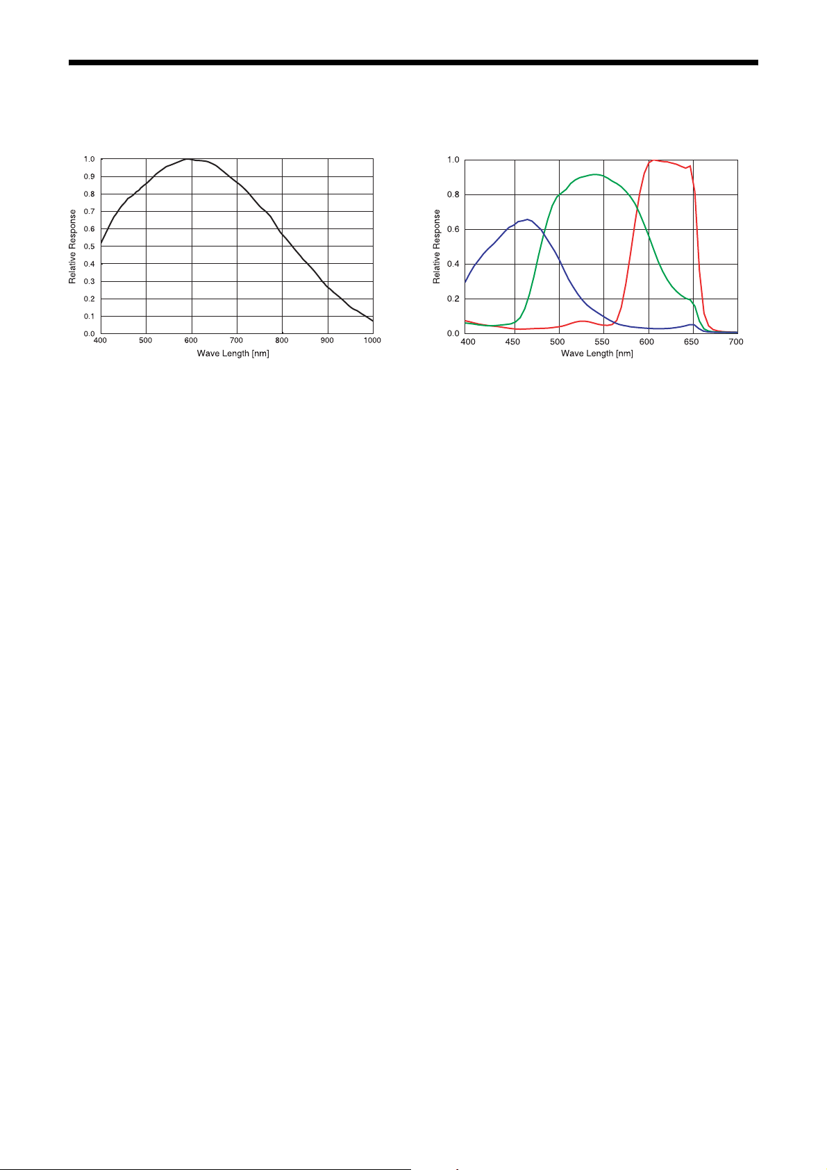
Spectral Sensitivity Characteristics (Typical Values)
XCU-CG160 XCU-CG160C
43
Page 44
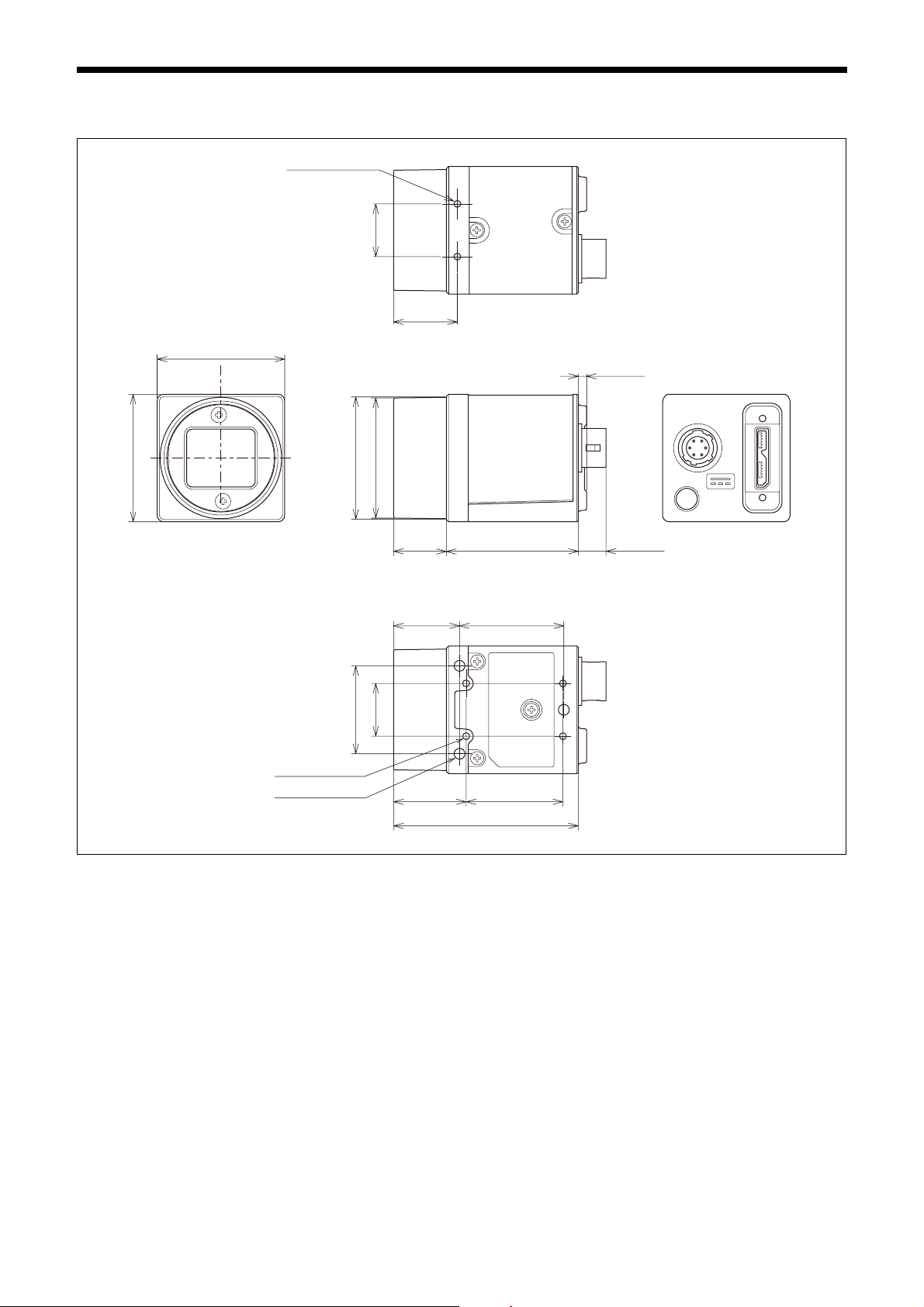
Dimensions
29 (1 3/16)
)
16
/
3
2 -M2 Depth 3
)
8
/
1
)
2
/
1
12 (
)
8
/
1
14.5 (19/32)
1.9 (3/32)
29 (1
Ø27.6 (1
)
16
/
13
20 (
4 -M2 Depth 3
3 -M3 Depth 3
Ø27.3 (1
12 (
15 (19/32)
)
2
/
1
12 (
16.5 (
1
/2)
21
/32) 22 (7/8)
42 (1
30 (1
23.7 (
11
/16)
3
/16)
15
/16)
6.3 (
1
/4)
Unit: mm (inches)
44
Page 45

Sony reserves the right to change specifications of the products and discontinue products without notice.
Technical information contained herein is for reference only and does not convey any license by any implication or
otherwise under any intellectual property right or other right of Sony or third parties.
Sony cannot assume responsibility for any right infringements arising out of the use of this information.
Sony Corporation
 Loading...