

Sony XCL-X700, XCL-V500 Technical Manual

Digital Video
Camera Module
Technical Manual
A-C3H-100-11 (1)
XCL-X700/V500
2004 Sony Corporation

Table of Contents
Overview
Functions of the XCL-X700
What is the Camera Link? ........................................ 4
Features ..................................................................... 4
System Components................................................. 6
Connection Diagram ................................................. 6
Location and Function of Parts and Controls ........ 7
Front/Top/Bottom ........................................................ 7
Rear............................................................................ 8
Connecting the cables ................................................ 9
About the Camera Modes ....................................... 11
■ Normal Mode (when operating in external
synchronization) .................................................... 11
■ Restart/ Reset mode (when operating in external
synchronization) .................................................... 11
■ Trigger Mode1 (when operating in external
synchronization with the shutter operation controlled
by a trigger pulse width) ........................................ 12
■ Trigger Mode2 (when operating in internal
synchronization with the shutter operation controlled
by a trigger pulse width) ........................................ 12
About the Camera Functions ................................. 13
■ Electronic Shutter Function ................................... 13
■ Overlap Function ................................................... 13
■ External Clock Input Function ............................... 15
■ Binning Function .................................................. 16
■ High-rate scan I Function ...................................... 17
■ High-rate scan II Function ..................................... 19
Input/Output Signal Specifications........................ 24
■ External-HD/VD input phase specifications .......... 24
■ External-HD Input Specifications .......................... 25
■ External-VD Input Specifications .......................... 25
■ HD/VD Output Specifications (only for the DC IN
connector) ............................................................. 25
■ Trigger Pulse Specifications.................................. 26
■ WEN Output Specifications (only for the DC IN
connector) ............................................................. 26
■ DVAL/LVAL/FVAL Output Specifications (only for the
DIGITAL IF connector) .......................................... 26
■ External-CLK Specifications (common to the DC IN
/DIGITAL IF connectors) ....................................... 26
CCD Output Waveform Timing Chart ..................... 27
Functions of the XCL-V500
XCL-X700/V500
About the Camera Modes ....................................... 28
■ Normal Mode (when operating in external
synchronization) .................................................... 28
■ Restart/ Reset mode (when operating in external
synchronization) .................................................... 28
2

■ Trigger Mode1 (when operating in external
synchronization with the shutter operation controlled
by a trigger pulse width) ........................................ 29
■ Trigger Mode2 (when operating in internal
synchronization with the shutter operation controlled
by a trigger pulse width) ........................................ 29
About the Camera Functions ................................. 30
■ Electronic Shutter Function ................................... 30
■ Overlap Function ................................................... 30
■ External Clock Input Function ............................... 32
■ Binning Function ................................................... 33
■ High-rate scan I Function ...................................... 34
■ High-rate scan II Function ..................................... 36
Input/Output Signal Specifications........................ 39
■ External-HD/VD input phase specifications .......... 39
■ External-HD Input Specification ............................ 40
■ External-VD Input Specifications .......................... 40
■ HD/VD Output Specifications (only for the DC IN
connector) ............................................................. 40
■ Trigger Pulse Specifications.................................. 41
■ WEN Output Specifications (only for the DC IN
connector) ............................................................. 41
■ LVAL/FVAL Output Specifications (only for the
DIGITAL IF connector) .......................................... 41
■ External-CLK Specifications (common to the DC IN
/DIGITAL IF connectors) ....................................... 41
CCD Output Waveform Timing Chart ..................... 42
Camera Control Command
Specifications
Appendix
Overview .................................................................. 43
Serial Communication Specifications ....................... 43
Command System .................................................... 43
Command Format .................................................... 43
Command Input and Response................................ 43
Command Specifications ....................................... 44
Camera Control Commands..................................... 44
Setting Value Control Commands ............................ 46
Other Commands ..................................................... 46
Command List ......................................................... 47
Specifications .......................................................... 48
Spectral Sensitivity Characteristics
(Typical Values) ..................................................... 49
XCL-X700 Dimensions ........................................... 50
XCL-V500 Dimensions ........................................... 51
Available Accessory Lenses .................................. 52
XCL-X700/V500
3

Overview
Overview
The XCL-X700/V500 is a monochrome digital video
camera module. This camera module outputs digital
images utilizing LVDS via the digital interface
connector.
What is the Camera Link?
The Camera Link is specifications defined for
industrial cameras, and the term used collectively
forcall products meeting these specifications. In the
Camera Link specification, digital parallel signals are
converted to LVDS serial signals and sent out from the
camera module. These signals are sent to the interface
board for the camera (frame grabber) via the cable, and
decoded to the original digital parallel signals in the
interface board. The XCL-X700/V500 is equipped
with a connector compatible with the Camera Link
specifications, and can be connected to any interface
board compatible with the XCL-X700/V500 using the
specified standard cable.
High image quality
The XCL-X700 (XGA) has a progressive scan CCD of
800,000 pixels. The XCL-V500 (VGA) has a
progressive scan CCD of 330,000 pixels. Both cameras
produce high-resolution images. By adopting square
pixels, images can be processed using the original
aspect ratio without a converting procedure.
Various mode settings
Sending a command from the host device allows the
following mode settings.
• Gain
• Read mode: normal /binning
• High rate scan
• Synchronized input/output
• 75 Ω termination
• Shutter: Normal/Trigger shutter
• Shutter speed
External synchronization
Features
Digital interface connector
Equipped with a Camera Link compatible connector.
The XCL-X700 can output a digital image at 30
frames per second; the XCL-V500 can output a digital
image at 60 frames per second.
XCL-X700/V500
HD (horizontal drive), VD (vertical drive) signals: The
camera module automatically detects the HD and VD
signals input and externally synchronized with those
signals.
Setting the operating speed by inputting
an external clock
You can operate the camera module at the desired
clock frequency (frame rate) by inputting external
clock signals of an arbitrary frequency from normal to
1/2.
4

Internal sync signal output
You can output HD or VD signals from the 12-pin
connector by changing the setting using a command
sent from the host device.
Electronic shutter function
Shutter speed can be selected from a wide range or in
flickerless (FL) mode.
External trigger shutter function
(1/4 to 1/100000 sec.)
You can obtain a freeze picture by inputting an
external trigger. This function is useful to shoot a fastmoving object clearly.
Overview
High rate scan
The camera module can limit the number of effective
video output lines to achieve high frame rates,
enabling high-speed image processing.
Binning
By “binning” two pixels that align vertically, you can
acquire sensitivity as well as a frame rate twice as high
as those in the normal mode, when using the electronic
shutter.
Body fixing
The screw holes to install the camera module are
located under the front panel (the CCD reference
plane). Installing the camera module using these holes
minimizes deviation of the optical axis.
Note
The CCD is driven at high speed during a High-rate
scan or Binning operation. In this situation, if intense
light is input to the camera, the peripheral areas of the
video image may be affected. In such a situation,
adjust the amount of light using the iris.
XCL-X700/V500
5
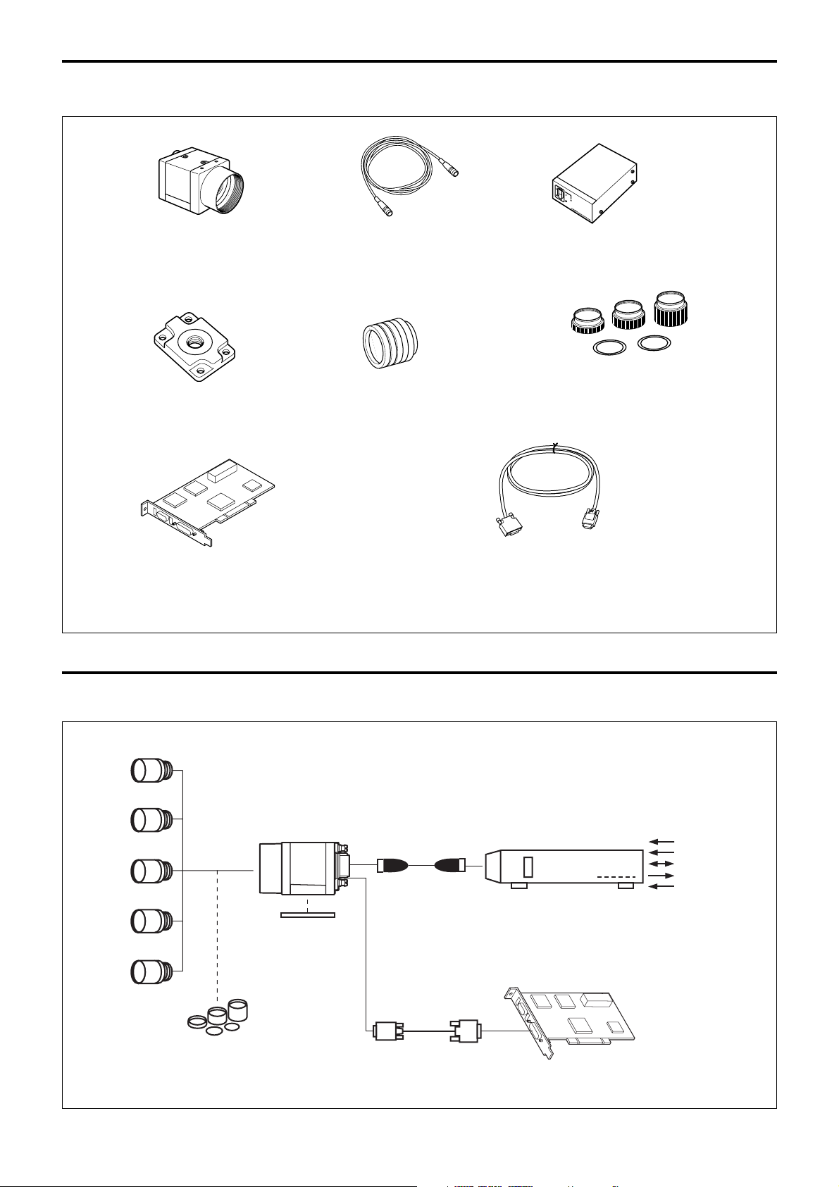
System Components
Overview
Video camera module
XCL-X700/V500
Tripod adaptor
VCT-333I
(Insulated type)
Camera module interface board
Camera cables
CCXC-12P02N(2 m)
CCXC-12P05N(5 m)
CCXC-12P10N(10 m)
CCXC-12P25N(25 m)
C-mount lenses
VCL-50Y-M
VCL-25Y-M
VCL-16Y-M
VCL-12YM
VCL-08YM
Camera Link-compatible
interface board (commercially
available)
Insert this to the PCI bus slot of
the host device such as a PC.
Camera adaptor
DC-700/700CE
Close-up ring kit
LO-77ERK
Sony camera-compatible
cable produced by
Sumitomo 3M Limited
(commercially available)
Camera Link cable
1MA26-4560-OSC-200 (2 m, 6.6 ft)
500 (5 m, 16.4 ft)
A00 (10 m, 32.8 ft)
Connection Diagram
C-mount lens
VCL-08YM
VCL-12YM
VCL-16Y-M
VCL-25Y-M
VCL-50Y-M
Recommended lens for the XCL-X700: VCL-12YM
Recommended lens for the XCL-V500: VCL-08YM/12YM/16Y-M/25Y-M/50Y-M
XCL-X700/V500
Tripod adaptor
VCT-333I
Close-up ring kit
LO-77ERK
Camera cables
CCXC-12P02N
CCXC-12P05N
CCXC-12P10N
CCXC-12P25N
Camera Link cable
AC
CLOCK
HD/VD
WEN
TRIG
Camera adaptor
DC-700/700CE
(Conforms to new EIAJ 12-pin
assignments)
Camera module interface board
XCL-X700/V500
6
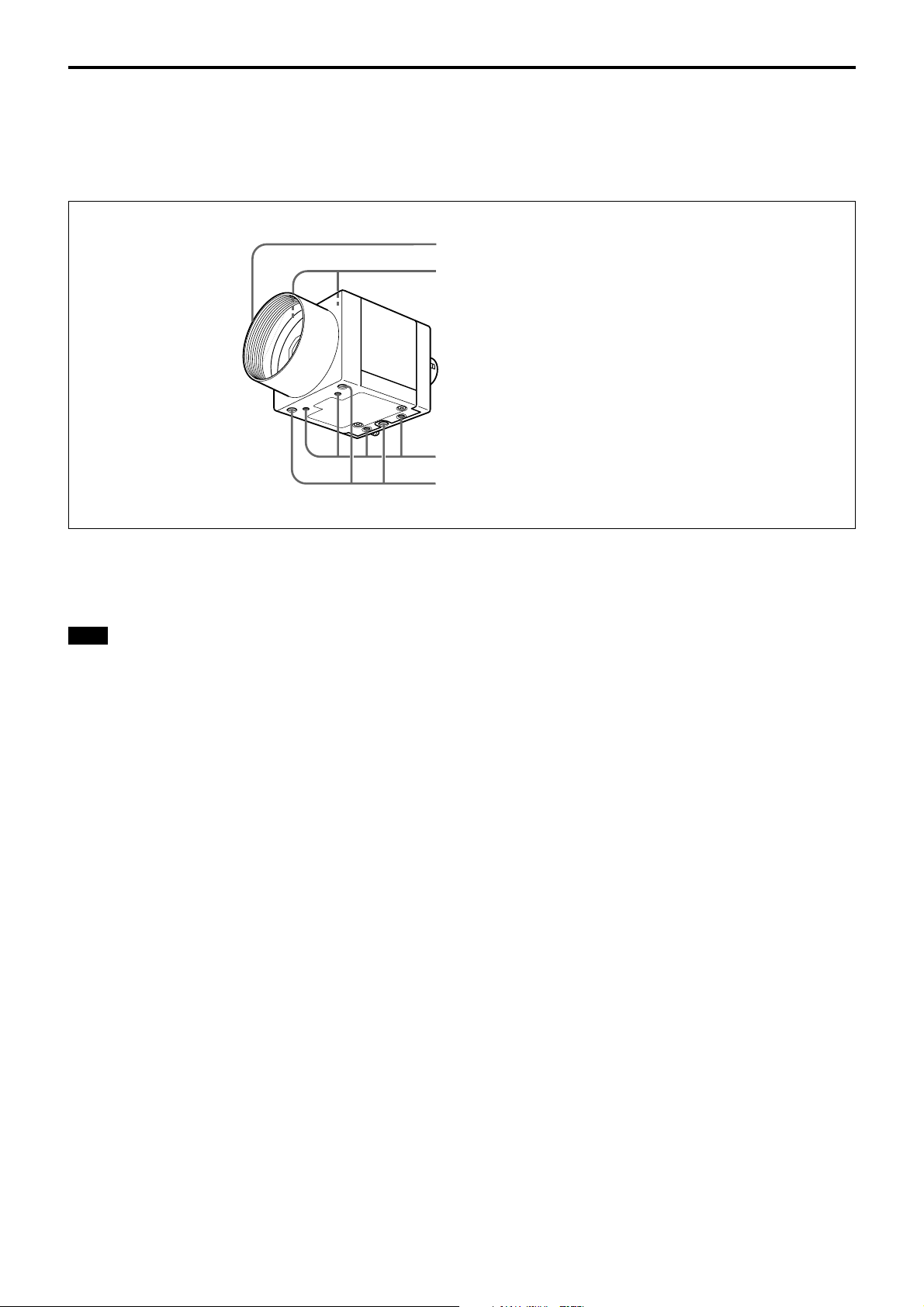
Location and Function of Parts and Controls
Front/Top/Bottom
1 Lens mount (C-mount)
2 Guide holes (at the top)
3 Tripod screw holes (at the bottom)
4 Reference holes (at the bottom)
Overview
1 Lens mount (C-mount)
Attach any C-mount lens, such as the VCL-12YM
standard lens, or other optical equipment.
Note
Be sure that the lens does not project more than 7 mm
(9/32 inch) from the lens mount.
2 Guide holes (at the top)
These screw holes help to lock the camera module.
3 Tripod screw holes (at the bottom)
These four screw holes on the bottom are for installing
the camera module on a tripod. To install on a tripod,
you will need to install the VCT-333I tripod adaptor
using these holes on the bottom of the camera.
4 Reference holes (at the bottom)
These precision screw holes are for locking the camera
module. Locking the camera module using these holes
secures the optical axis alignment.
XCL-X700/V500
7
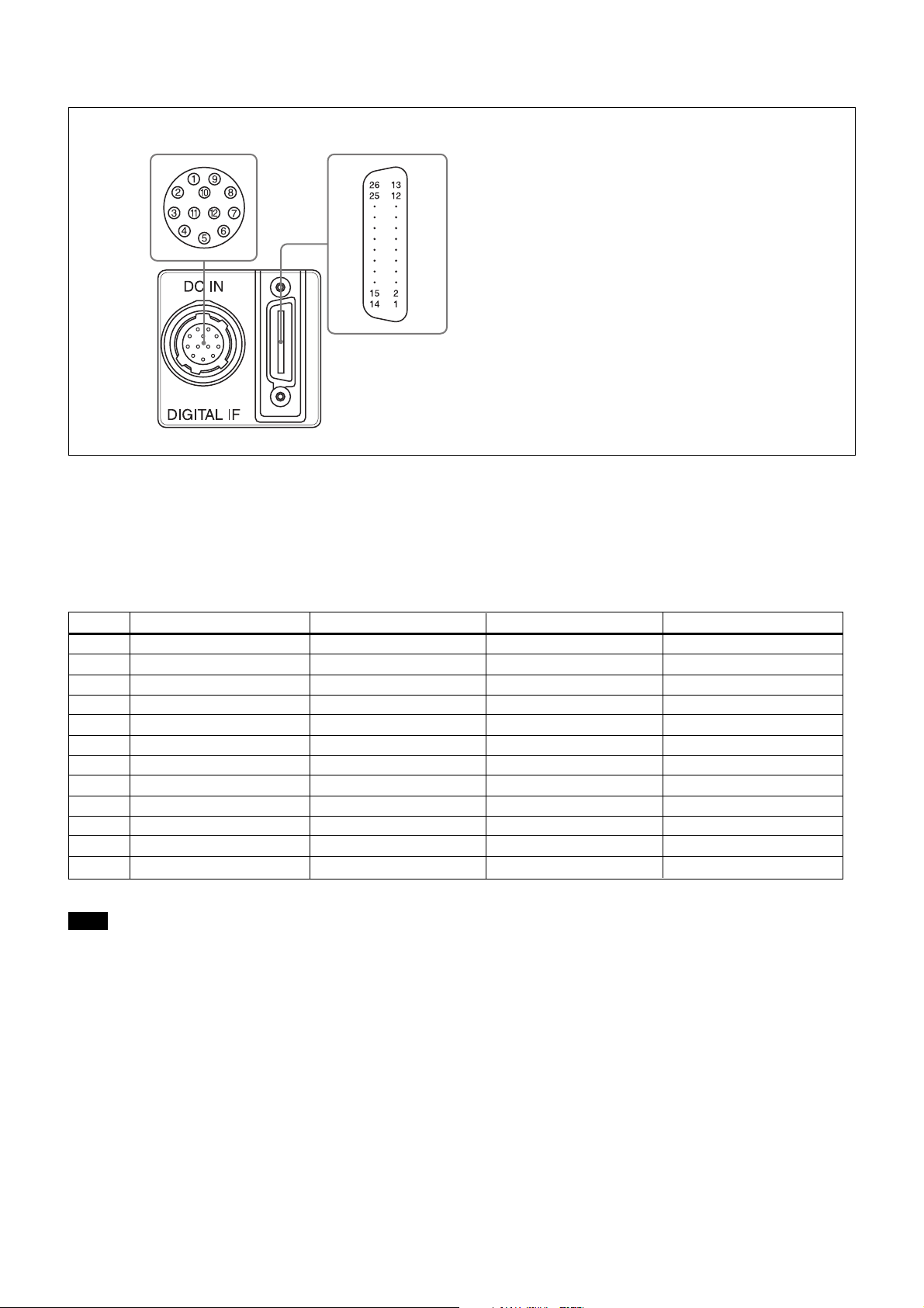
Rear
Overview
5 DC IN (DC power input) connector (12-pin)
65
5 DC IN (DC power input) connector (12-pin)
You can connect a CCXC-12P05N camera cable to
input the +12 V DC power supply. When a sync signal
generator is connected to this connector, the camera
module is synchronized with the external sync signals.
The pin configuration of this connector is as follows.
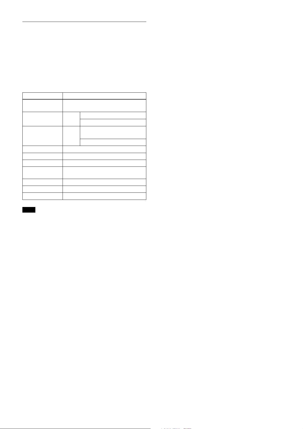
6 DIGITAL IF (Interface) connector (26-pin)
Pin No. Camera sync output External Sync mode (HD/VD) Restart reset External trigger shutter
1 Ground Ground Ground Ground
2 +12 V DC +12 V DC +12 V DC +12 V DC
3——— —
4 Clock (+) input (Signal) Clock (+) input (Signal) Clock (+) input (Signal) Clock (+) input (Signal)
5 HD output (Ground) HD input (Ground) HD input (Ground) HD input (Ground)
6 HD output (Signal) HD input (Signal) HD input (Signal) HD input (Signal)
7 VD output (Signal) VD input (Signal) Reset (Signal) VD input (Signal)
8——— —
9 Clock (–) input (Signal) Clock (–) input (Signal) Clock (–) input (Signal) Clock (–) input (Signal)
10 — — — WEN output (Signal)
11 — — — Trigger pulse input (Signal)
12 VD output (Ground) VD input (Ground) Reset (Ground) VD input (Ground)
Note
When you operate a camera module by inputting an
external clock signal, input the external signal using
the VIDEO connectors of the DC-700. Make sure to
input external clock signals that meet the following
specifications to both connectors.
Specifications for the external clock signal
Amplitude: LVDS (Low-Voltage Differential Signaling)
system using a 3.3 volt IC.
Frequency: XCL-X700: 29.5 MHz to 59.0 MHz
XCL-V500: 24.545 MHz to 49.09 MHz
Connections: Input a CLOCK (+) signal to the VIDEO 1
connector of the DC-700.
Input a CLOCK (–) signal to the VIDEO 2
connector of the DC-700.
XCL-X700/V500
8
Overview
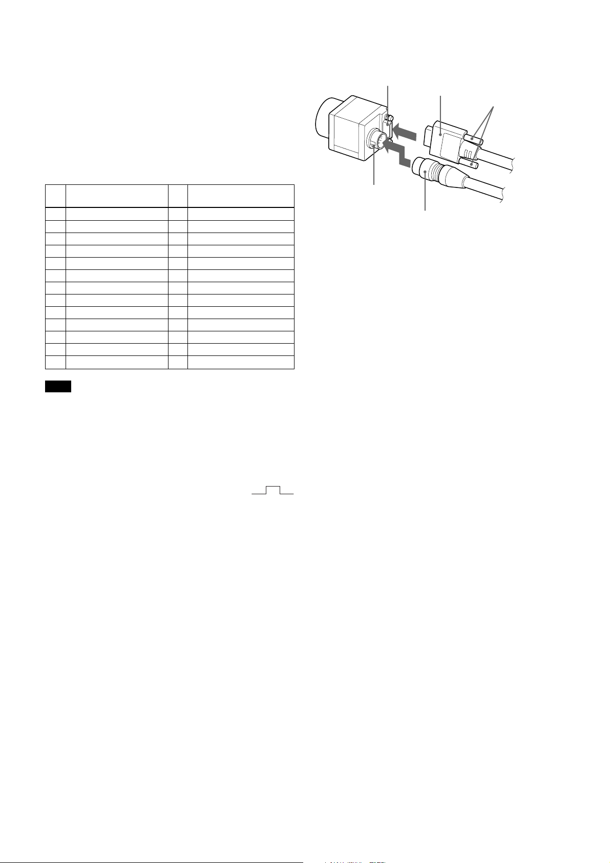
6 DIGITAL IF (Interface) connector (26-pin)
You can connect a Camera Link cable to this
connector to control a camera module from a host
device utilizing the serial communication protocol
while outputting a video signal from the camera
module. You can input the external trigger signal/
external sync signal via the 26-pin connector and
operate a camera module in the external trigger mode/
external synchronization mode. The pin configuration
of this connector is as follows.
Pin
No. No.
1 INNER_SHIELD (Ground) 14 INNER_SHIELD (Ground)
2 X0– output (Signal) 15 X0+ output (Signal)
3 X1– output (Signal) 16 X1+ output (Signal)
4 X2– output (Signal) 17 X2+ output (Signal)
5 XCLK– output (Signal) 18 XCLK+ output (Signal)
6 X3– output (Signal) 19 X3+ output (Signal)
7 Ser TC+ (Signal) 20 Ser TC– (Signal)
8 Ser TFG– (Signal) 21 Ser TFG+ (Signal)
9 TRIG (–) input (Signal) 22 TRIG (+) input (Signal)
10 HD (+) input (Signal) 23 HD (–) input (Signal)
11 VD (–) input (Signal) 24 VD (+) input (Signal)
12 CLOCK (+) input (Signal) 25 CLOCK (–) input (Signal)
13 INNER_SHIELD (Ground) 26 INNER_SHIELD (Ground)
Digital signal
Pin
Digital signal
Connecting the cables
DIGITAL IF (Interface) connector
2
1
DC IN
connector
Connect the Camera cable to the DC IN connector and
the Camera Link cable to the DIGITAL IF (Interface)
connector respectively. When you connect the Camera
Link cable, turn the two Fastening screws on the
connector to secure the cable tightly.
Connect the other end of the Camera cable to the DC700/700CE and the other end of the Camera Link cable
to the camera module interface board.
Camera Link cable
4
3
Camera cable
Fastening screws
5
Note
When you operate a camera module by inputting an
external trigger signal via the 26-pin connector, make
sure to input external trigger signals that meet the
following specifications to both the two pins.
Specifications for the External Trigger Signal
Amplitude: LVDS using a 3.3 volt IC Polarity: positive
Connections: Input a TRIG (–) signal to the 9th pin.
Input a TRIG (+) signal to the 22nd pin.
XCL-X700/V500
9
About the camera control method
You can control the camera from host device such as a
PC. The following table shows the control functions.
You can send a command corresponding to the control
items, with parameters for the desired settings, if
necessary, from the host device to control the camera.
Refer to “Camera Control Command” on page 43 for
details on how to send a command, the commands, and
their parameters.
Control functions Description
Operating mode Normal/Restart reset/trigger mode 1/
trigger mode 2
Shutter speed Normal XCL-X700: OFF (1/30) - 1/
XCL-V500: OFF (1/60) - 1/30000
Trigger Internal setting: OFF (the same as
above) - 1/100000
Setting by trigger pulse width
Gain 0 to +18 dB
Binning function OFF/ON
High-rate Scan function OFF/ON
HD/VD signal I/O External sync signal input / Internal sync
signal output
External trigger input 26-pin connector / DC-700/700CE
75 Ω termination ON/OFF
Master clock Internal / External
20000
Overview
Note
Make sure to supply power to the camera module and
confirm that the camera module is operating before
inputting a sync or trigger signal. If you input external
signals to a camera module without the power
supplied, this may cause a malfunction of the camera
module.
XCL-X700/V500
10

Functions of the XCL-X700
Functions of the XCL-X700
About the Camera Modes
■ Normal Mode (when operating in external synchronization)
Description: Outputs each independent pixel video
signal for 1/29.2 second. Internal or external
synchronization is recommended.
1/29.2 s (796H)
External-VD
External-HD
Video out
BLKG interval
Effective image interval
Application: Use this mode to provides continuous
standard video output.
1/29.2 s (796H)
Internal-VD occurs
1H later.
■ Restart/ Reset mode (when operating in external synchronization)
Description: Outputs each independent pixel video
signal of a single shot for which exposure time is
proportional to the interval of External-VD signals,
synchronized with External-VD signals. External
synchronization is recommended.
Application: Use this mode when you cannot gain
satisfactory sensitivity in the Normal Mode, or
when you want to observe the trail of a moving
object.
External-VD
External-HD
Video out
XCL-X700/V500
1/29.2 s (796H)
1/14.6 s (1592H) 1/29.2 s (796H)
Internal-VD occurs
1H later.
11
Functions of the XCL-X700
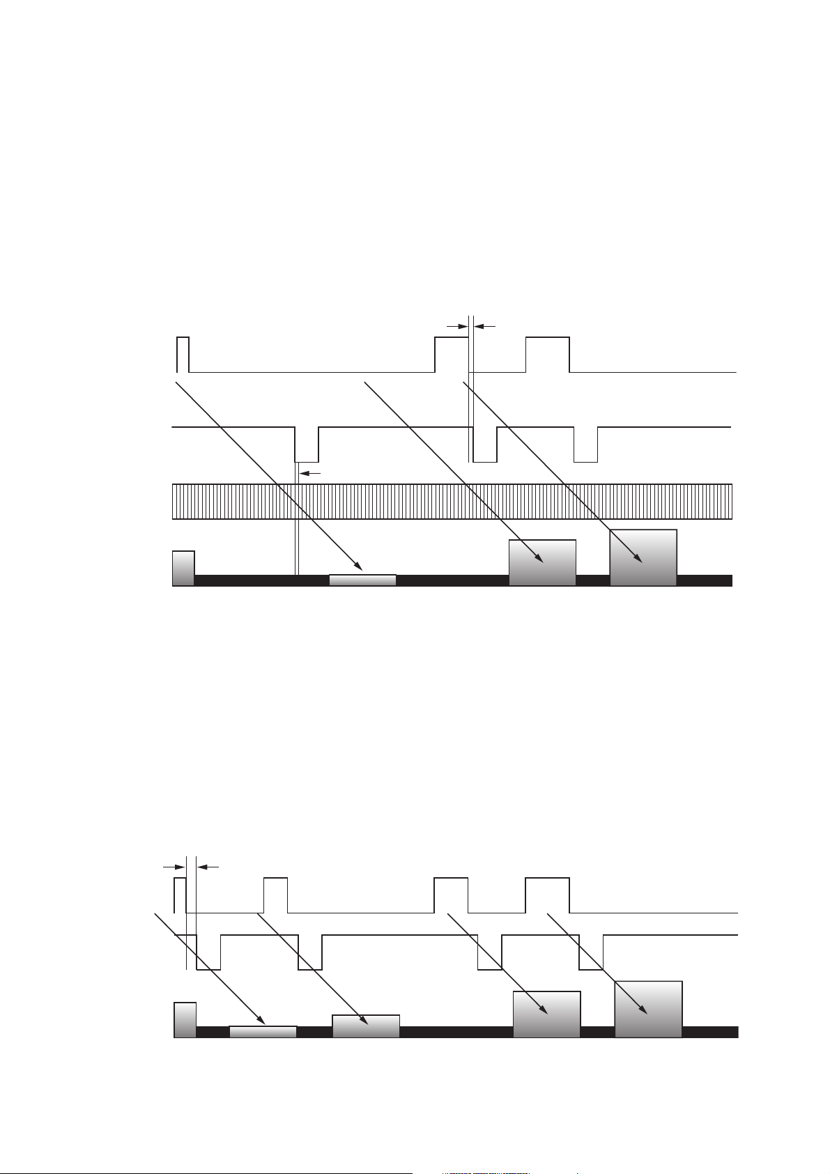
■ Trigger Mode1 (when operating in external synchronization with the shutter operation controlled by a trigger pulse width)
Description: Controls the shutter synchronized with
externally input trigger signals and outputs each
independent pixel video signal of a single shot
synchronized with External-VD signals. External
synchronization is recommended. We recommend
that external trigger signals, External-VD signals,
and External-HD signals are all synchronized with
each other, and the ratio of the external trigger
External trigger
External-VD
Internal-VD occurs
1H later.
External-HD
signals and the External-VD signals should be 1:1.
When you use the fixed speed trigger shutter, input
the External-VD signals synchronized to the output.
Application: Use this mode to capture fast-moving
objects in a precise position synchronized with
External-VD signals because in this mode, the
shutter is controlled by inputting external trigger
signals.
1H or more
Video out
■ Trigger Mode2 (when operating in internal synchronization with the shutter operation controlled by a trigger pulse width)
Description: Controls the shutter synchronized with
externally input trigger signals and outputs each
independent pixel video signal of a single shot in
synchronization with externally input trigger
signals after a certain period. Internal or external
synchronization is recommended.
1 to 3H
External trigger
Internal-VD
Application: Use this mode to obtain video output
synchronized with externally input trigger signals
after a certain period without inputting ExternalVD signals as in case of the Trigger Mode1.
Video out
XCL-X700/V500
12
About the Camera Functions
Functions of the XCL-X700
■ Electronic Shutter Function
Normal Shutter
The electronic shutter is used for continuous video
output to capture fast-moving objects clearly. Shutter
speeds of 1, 1/100, 1/125, 1/250, 1/500, 1/1000, 1/2000,
1/4000, 1/10000, 1/20000 second are supported. Normal
Mode is supported for the Camera Mode.
External Trigger Shutter
The electronic shutter is used synchronized with
externally input trigger signals to capture fast-moving
objects clearly and in a precise position. There are two
types of external trigger shutter: an external trigger
shutter controlled by external input trigger pulse width
and a fixed speed external trigger shutter synchronized
with the timing of an externally input trigger. Trigger
Mode1 and Trigger Mode 2 are both supported for the
Camera Mode.
• Fixed external trigger shutter speeds:
1, 1/100, 1/125, 1/250, 1/500, 1/1000, 1/2000,
1/4000, 1/10000, 1/25000, 1/50000, 1/100000
second are supported.
controlled by external trigger pulse width:
You can obtain an arbitrary shutter speed by setting
the external trigger pulse width to the range of 2 µsec
to 1/4 sec.
- When trigger signals are input through the 12-pin
connector
External trigger pulse width shutter speed = external
trigger pulse width + 6 µsec
- When trigger signals are input through the
DIGITAL IF connector
External trigger pulse width shutter speed = external
trigger pulse width + 5 µsec
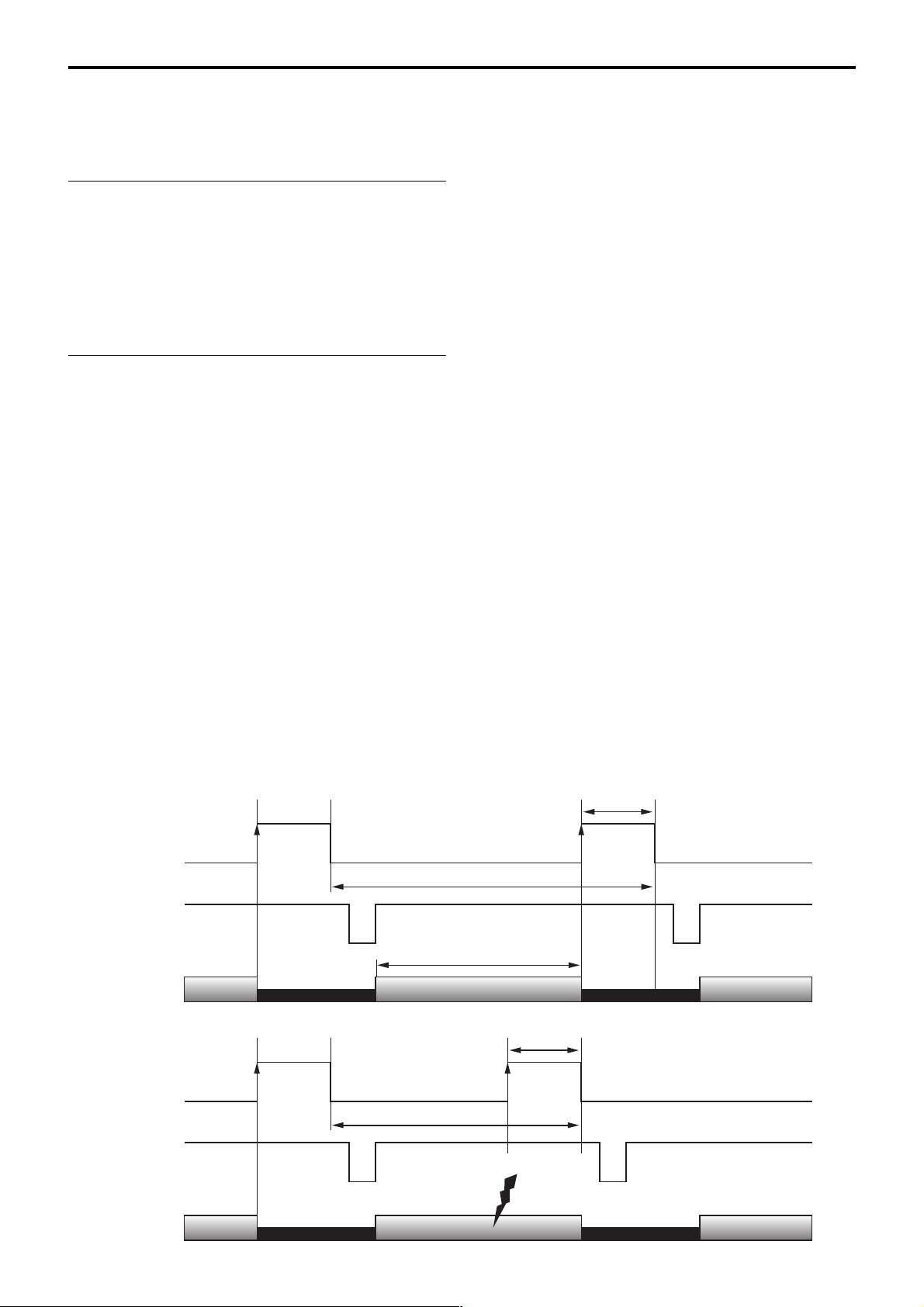
■ Overlap Function
One way to increase frame rate while using slow to
mid-speed trigger pulse width shutter in the case of
previous analog cameras 1 is to input the rising edge
of the external trigger signals during the effective
image interval as indicated in case 2. Noise is
generated when the rising edge of the external trigger
signal is input during the effective image interval,
however, and the effective video output deteriorates
and becomes unusable. As a consequence, we must
input the signal after the effective image interval and
we cannot increase frame rate indicated as T2 in the
case of 2.
The frame rate results in:
• External trigger shutter speed is
Previous analog cameras 1
External
trigger
T1 = approx. Effective image interval + Exposure time
Internal-VD
Video out
Previous analog cameras 2
External trigger
T2 = approx. Effective image interval
T1 = approx. Effective image interval + exposure time
controlled by the trigger signals
Exposure
time
Effective image interval
Exposure
time
Internal-VD
Video out
XCL-X700/V500
Noise
generated
13
Functions of the XCL-X700
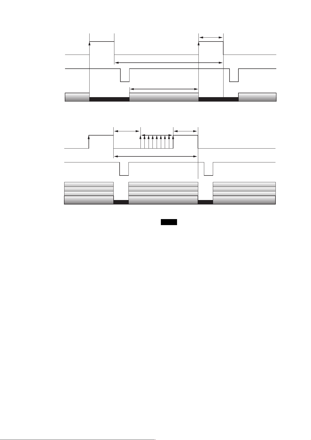
This camera module 1
External
trigger
Internal-VD
Video out
This camera module 2
External trigger
Internal-VD
Exposure
time
T1 = approx. Effective image interval + Exposure time
Effective image interval
B
10H
T2 = approx. Effective image interval
A
No noise generated
Exposure
time
Video out
This camera is equipped with an Overlap function
which eliminates the effect of noise accompanying the
increase of frame rate while using a slow to mid-speed
shutter. This camera module can be used in the
operation mode that can increase frame rate without
noise generation as indicated in 2 as well as that in 1
that is equal to the operation of previous analog
cameras. Thanks to this function, exposure time can be
prolonged, and shutter speed can be slowed down,
keeping a high frame rate by putting the rising edge of
the external trigger earlier as indicated by A in 2. Be
aware that the maximum interval in which you can
input the rising edge of the external trigger is in the
range of 10 H after the falling edge of the previous
trigger to the rising edge of the next trigger as
indicated by B in 2. Trigger Mode1 and 2 are
supported for the Camera Mode.
Notes
• The description above is the operation while using a
slow to mid-speed shutter controlled by the external
trigger pulse width. When using a fixed speed
external trigger shutter, be sure to input the rising
edge of the next trigger after the internal exposure
time and at the appropriate timing so as not to affect
the effective image interval corresponding to the
current trigger signal. Be aware that if this condition
is not observed, the following may occur.
- To which frames the effective images
corresponding to the external trigger signals will
be output may be inconsistent.
- Double exposure
- Signals in the blanking interval may be output in
the effective image interval.
• If you change settings such as Camera Mode while
using the Overlap function, video output may be
disturbed.
• A deviation of a maximum about 1H is generated for
the exposure time by the Overlap function, so the
supported shutter speeds are limited to those for
which this exposure deviation can be ignored.
XCL-X700/V500
14
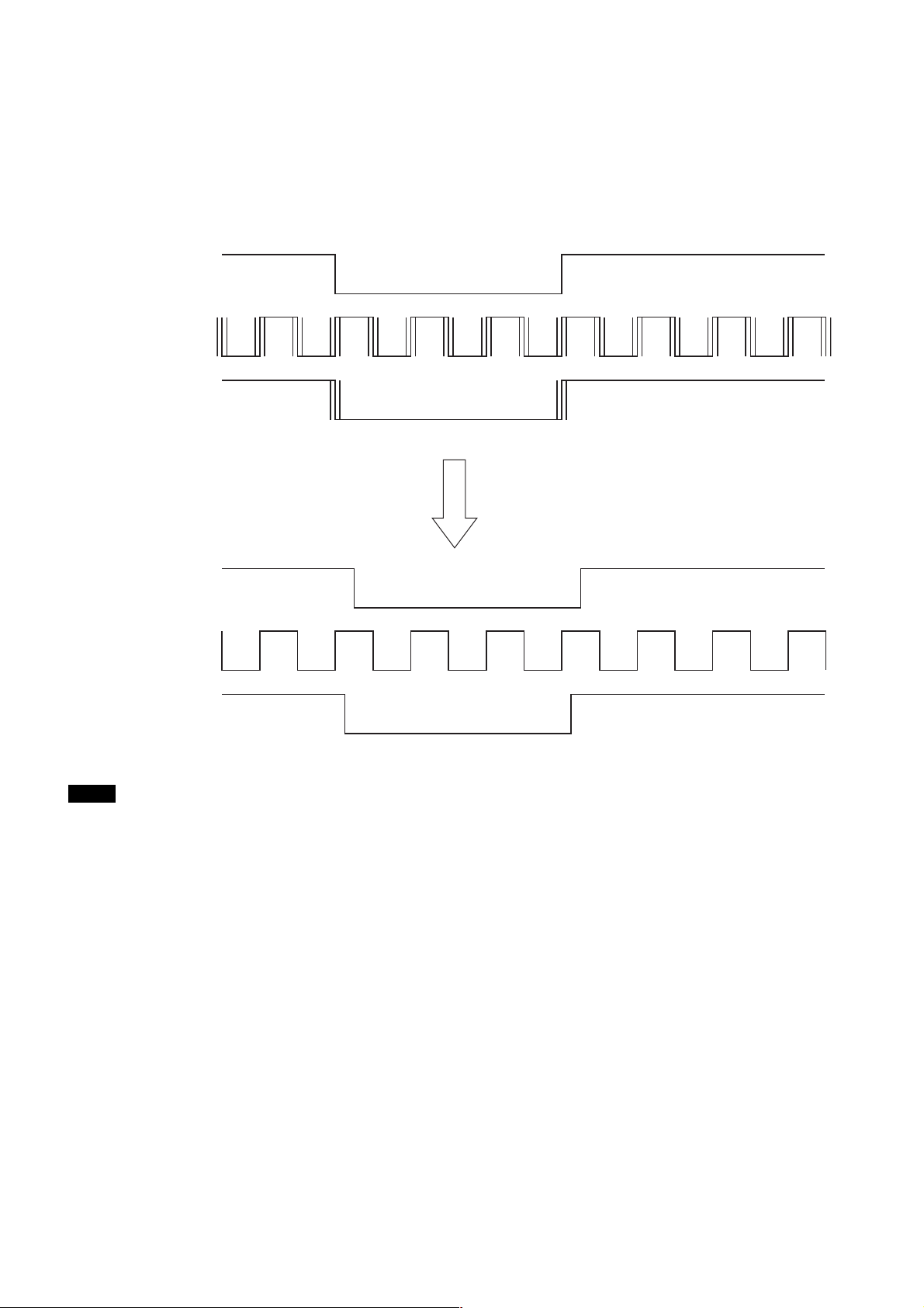
■ External Clock Input Function
Functions of the XCL-X700
Previously, the operating speed of a camera was fixed.
This camera can change its operating speed from the
normal speed to half of that.
Previous cameras
External-HD
Internal-CLK
Internal-HD
This camera
By utilizing the external clock input function, clock
jitter is completely eliminated.
All modes are supported for the Camera Mode.
External-HD
External-CLK
Internal-CLK
Internal-HD
Notes
• Be aware that the shift of phase occurs in the range of
– 2 × CLK to 0 (reference: External-CLK) for
Internal-HD signals depending on the timing when
the power is turned on. The amount of the shift is not
always the same and varies within the range
described above every time the power is turned on.
• Be aware that noise is generated when the Internal/
External clock is switched.
XCL-X700/V500
15

Functions of the XCL-X700
The speed of the electronic shutter is determined by
the frequency of the external input clock signals.
Calculate the shutter speed according to the following
formula.
Normal shutter speed:
Exposure time = { 1106 × A + 164 × (A–1) × 187 }
× 2/ECLK
Shutter speed = 1/Exposure time
A: 1 (1/20000 s)
2 (1/10000 s)
6 (1/4000 s)
12 (1/2000 s)
23 (1/1000 s)
46 (1/500 s)
93 (1/250 s)
186 (1/125 s)
232 (1/100 s)
ECLK: External clock frequency: 59 (MAX) to 29.5
(MIN) MHz
Fixed external trigger shutter speeds:
Exposure time = { A + B × 1270 + 144 } × 2/ECLK
Shutter speed = 1/Exposure time
A: 151 B: 0 (1/100000 s)
446 0 (1/50000 s)
1036 0 (1/25000 s)
2806 0 (1/10000 s)
7231 0 (1/4000 s)
14606 0 (1/2000 s)
0 23 (1/1000 s)
0 46 (1/500 s)
0 93 (1/250 s)
0 186 (1/125 s)
0 232 (1/100 s)
■ Binning Function
Mixed signals for vertically adjacent pixels of the
output of the CCD are output in this function and
sensitivity and frame rate are approximately doubled.
When the Normal shutter is OFF in the Normal Mode,
the frame rate is doubled but exposure time is halved,
so that the effect of this function is cancelled out as in
the Reset/Restart mode. Both sensitivity and frame
rate are doubled when the Normal shutter is ON.
All modes are supported for the Camera Mode.
But High-rate scan II in Trigger Mode2 is not
supported.
External trigger pulse width shutter
speed:
• When trigger signals are input through the 12-pin
connector
Exposure time = { external trigger pulse width
+ 1 µs} + 144 × 2/ECLK
•When trigger signals are input through the DIGITAL
IF connector
Exposure time = { external trigger pulse width }
+ 144 × 2/ECLK
Shutter speed = 1/Exposure time
Be aware that the external trigger pulse width should
be set in the range of 3 µsec to 1/4 sec when inputting
external clock signals.
XCL-X700/V500
16
 Loading...