

Sony XCL-U100 Technical Manual

Digital Video
Camera Module
A-D9A-100-11 (1)
Technical Manual
XCL-U100
© 2009 Sony Corporation

Table of Contents
Overview
Features .................................................................. 3
Typical CCD Phenomena ..................................... 4
System Components .............................................. 5
Connection ............................................................. 6
Location and Function of Parts and Operation .. 7
Front/Top/Bottom ............................................... 7
Using a tripod ..................................................... 7
Rear .................................................................... 8
Connecting the cables ........................................ 9
Trigger signal specifications ............................ 10
DVAL/Exposure output specific (only DC IN
terminal) ......................................................... 10
Functions
1. Compatibility with previous model
XCL-5005......................................................... 11
2. Video output format........................................ 12
2.1. Port assignment ....................................... 12
2.2. Output data size ...................................... 12
3. Camera mode................................................... 13
3.1. Horizontal timing .................................... 13
3.2. Vertical timing ......................................... 14
3.2.1. Normal mode ......................................14
3.2.2. Binning mode ......................................15
3.2.3. Partial scan mode ................................16
3.2.4. Trigger mode .......................................18
3.2.5. Trigger binning mode ..........................19
3.2.6. Trigger partial scan mode ....................21
4. Shutter setting ................................................. 22
4.1. Preset shutter ........................................... 22
4.2. Arbitrary shutter setting .......................... 23
4.3. Overlap .................................................... 24
4.4. WEN-STRB ............................................ 24
5. DSP Operation................................................. 25
5.1. Signal processing block chart ................. 25
5.2. Digital clamp ........................................... 26
5.3. Digital gain ............................................. 26
5.4. Digital pedestal ....................................... 26
5.5. Gamma correction ................................... 27
5.5.1. Arbitrary setting method .....................27
5.5.2. Coefficient input method .....................27
5.6. 3 × 3 filter ............................................... 29
5.6.1. Mode 1 ................................................29
5.6.2. Mode 2 ................................................30
5.7. Binarization ............................................. 31
5.8. 8/10/12 bit depth selection ...................... 32
5.9. Grayscale chart ....................................... 32
Command format ..............................................33
Command input and response ...........................33
Command Specification ......................................34
Camera control commands ...............................34
AFE Setting Command .....................................34
Shutter / Trigger Setting Command ..................34
Binarization Setting Command ........................35
Digital Setting Command .................................35
Gamma Setting Command ................................35
Filter Setting Command ....................................35
Binning / Partial Setting Command ..................35
IN/OUT Setting Command ...............................36
Setting Value Control Command ......................36
Setting Initialization Command ........................ 36
Save Setting Command .....................................36
Read Setting Command ....................................36
Setting Value Accession Command ..................37
Others ................................................................38
Command Limitation ........................................38
Command List ......................................................39
Parameter List ......................................................40
Specifications
Specifications ........................................................41
Spectral Sensitivity Characteristics (Typical
Values) ...................................................................42
XCL-U100 Dimensions ........................................43
Camera Control Commands
General ................................................................. 33
Serial Communication Specifications .............. 33
Command system ............................................. 33
2
Table of Contents

Overview
The XCL-U100 is a black and white digital video
camera module. This camera module outputs digital
images utilizing LVDS via the DIGITAL IF (interface)
connector.
Features
External trigger shutter function (2 to
1/10,000 s)
You can obtain a still picture by inputting an external
trigger. This function is useful to shoot a fast-moving
object clearly.
Partial scan
The camera module can limit the number of the actual
video output lines to achieve high frame rates, enabling
high-speed image processing.
Overview
DIGITAL IF connector
Equipped with a Camera Link standard mini connector.
The XCL-U100 can output a digital image at 15 frames
per second.
Supports the Camera Link PoCL
Standard
The XCL-U100 supports the PoCL (Power over Camera
Link) standard. By connecting a PoCL-compatible
camera link cable to a PoCL-compatible camera module
interface board, you can power, control, and output
images from the camera using a single cable.
This module is also provided with a DC IN connector to
enable you to use a power adaptor and a camera module
interface board without support for PoCL (non-PoCL) to
operate the camera.
High image quality
The XCL-U100 has a progressive scan CCD of
2,000,000 pixels. This module produce high-resolution
images. By adopting square pixels, images can be
processed using the original aspect ratio without a
converting procedure.
Various mode settings
Sending a command from the host device allows the
following mode settings.
•Gain
• Read mode: normal/binning
• Partial scan
• Shutter: Normal/Trigger shutter
• Shutter speed
• Gamma
• Switching an output Bit Depth
• 3 × 3 filter
• Binarization
Electronic shutter function
Shutter speed can be selected from variety of available
speeds.
Body fixing
The screw holes to install the camera module are located
under the front panel (the CCD reference plane).
Installing the camera module on the front panel
minimizes deviation of the optical axis.
Gamma
You can switch to OFF or ON.
When you switch to ON, you can select from various
modes, and draw not only the default gamma line but
also an original gamma curve.
Switching an Output Bit Depth
You can select 8 bit output, 10 bit output, or 12 bit
output.
Binning
By “binning” two pixels that align vertically, you can
acquire a frame rate twice as high as that in the normal
mode.
3 × 3 filter
You can configure the 3 × 3 filter manually. Six different
table presets are also available.
Outline detection detects an outline from a picture and
outputs an image made up of the outline only.
Binarization
Outputs an binarized image. Sensitivity can be changed.
Note
The CCD is driven at high speed during a Partial scan or
Binning operation. In this situation, if intense light is
input to the camera, the peripheral areas of the video
image may be affected. In such a situation, adjust the
amout of light using the iris.
Features
3

Typical CCD Phenomena
The following effects on the monitor screen are
Overview
characteristic of CCD cameras. They do not indicate any
fault with the camera module.
Smear
This occurs when shooting a very bright object such as
electric lighting, the sun, or a strong reflection.
This phenomenon is caused by an electric charge
induced by infrared radiation deep in the photosensor. It
appears as a vertical smear, since the CCD imaging
element uses an interline transfer system.
Vertical aliasing
When you shoot vertical stripes or lines, they may
appear jagged.
Blemishes
A CCD image sensor consists of an array of individual
sensor elements (pixels). A malfunctioning sensor
element will cause a single pixel blemish in the picture
(This is generally not a problem.).
White speckles
While CCD image pickup device is made by an accurate
technique, imperceptible speckless may rarely come up
on the screen due to cosmic rays and so on. This is
connected to the principle of CCD image pickup device,
not a malfunction. And the white speckless are easy to
come up in the following conditions.
• Using the camera in high temperature
• When turning up the gain
Note
If strong light enters a wide area of the screen, the screen
may become dark. This is not a malfunction.
If this occurs, avoid strong light or adjust the lens iris to
reduce the light amount.
Note on laser beams
Laser beams may damage a CCD. You are cautioned
that the surface of a CCD should not be exposed to
laser beam radiation in an environment where a laser
beam device is used.
4
Typical CCD Phenomena
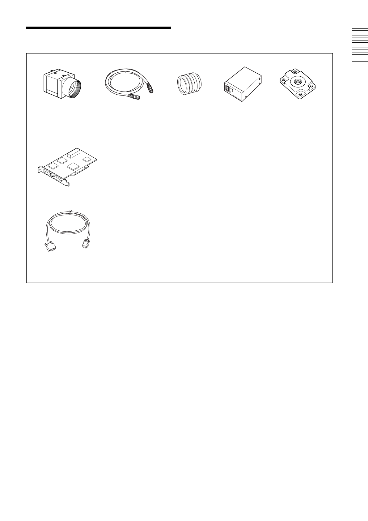
System Components
Overview
Video Camera Module
XCL-U100
Camera module interface
board
Camera Link cable
(Sony Camera-compatible)
Camera cable
CCXC-12P02N (2 m, 6.6 ft)
CCXC-12P05N (5 m, 16.4 ft)
CCXC-12P10N (10 m, 32.8 ft)
CCXC-12P25N (25 m, 82 ft)
Install the board in a PCI bus slot in devices such as a computer. Select a commercially
available interface board compatible with the Camera Link feature. You can use either a board
that supports PoCL, or one that does not.
Performance may also be dependent on the host device (e.g., Computer), so consult the
dealer if images are not displayed properly.
This cable connects to the DIGITAL IF connector on the rear panel of the camera module.
Image/control signals are transmitted via this cable.
If there is support for PoCL, power is also supplied at the same time. If you use a camera
module interface board with support for PoCL, be sure to use a camera link cable with support
for PoCL. The maximum usable length of a cable is 10 m, but the actual usable length may vary
based on the attributes of each cable. Keep this in mind when selecting a cable.
Spotted noise may appear in a specific brightness in the window according to the attribute of
the cable. If this noise is an obstacle, shorten the cable.
C-mount lens
High-resolution lens
Camera adaptor
DC-700/700CE
Tripod adaptor
VCT-333I (Insulated type)
System Components
5
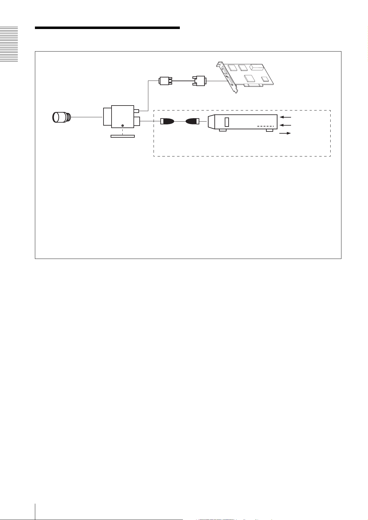
Connection
Overview
Camera Link cable
XCL-U100
C-mount lens
Camera cable
CCXC-12P02N
Tripod adaptor
VCT-333I
Power supply
You can supply power to the XCL-U100 using the following methods.
Using the DIGITAL IF connector
The XCL-U100 supports the PoCL (Power over Camera Link) standard. By connecting a PoCL-compatible camera link cable to a
PoCL-compatible camera module interface board, you can power, control, and output images from the camera using a single cable.
CCXC-12P05N
CCXC-12P10N
CCXC-12P25N
* If the camera module interface board for the camera supports PoCL, the
camera can be operated even if the items within the dashed line are not
connected.
Camera module interface board
Camera adaptor
DC-700/700CE
AC
TRIG
Ground/DVAL/
Exposure
(WEN line)
Using the DC IN connector
You can supply power via the DC IN connector using the power adapter.
Use DC-700/700CE which is the stable power source free from ripple or noise.
When both the DIGITAL IF and DC IN connectors are used, the power supply from the DC IN connector is given priority.
6
Connection
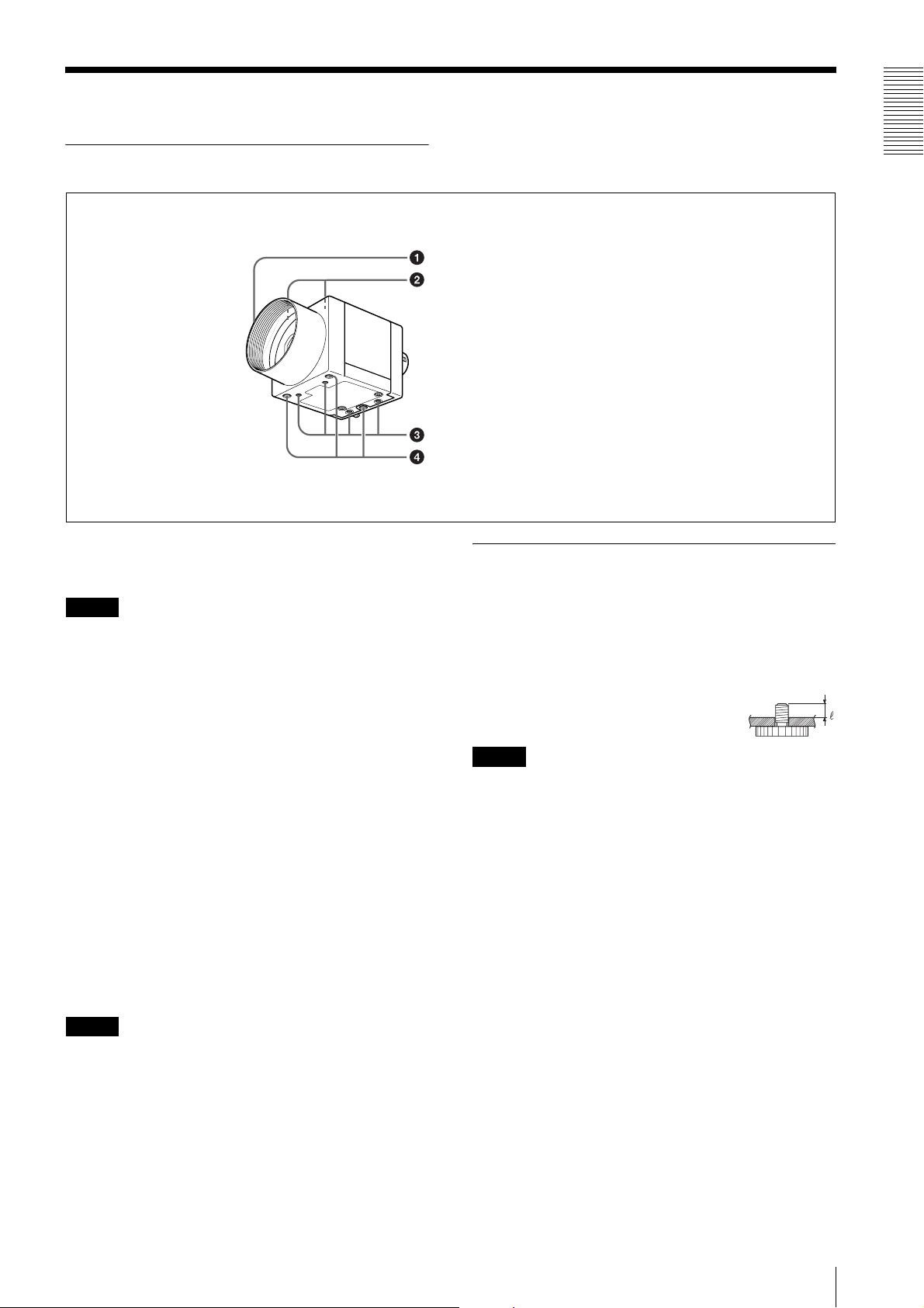
Location and Function of Parts and Operation
Front/Top/Bottom
a Lens mount (C-mount)
Attach any C-mount lens or other optical equipment.
Note
The lens must not project more than 10 mm (13/32 inch)
from the lens mount.
When you use the camera with the lens attached, the
resolution of the image output from the camera may
differ according to the performance of the lens. Note it
when you select a lens.
The performance of a lens may change according to the
aperture level.
If the resolution is not enough, adjust the aperture level.
b Guide screw holes (Top)
Overview
Lens mount (C-mount)
Guide screw holes (Top)
Guide screw holes/Tripod screw holes (bottom)
Reference screw holes (bottom)
Using a tripod
To use the tripod, install the tripod adaptor VCT-333I
(not supplied) on the camera module.
Use a tripod screw with a protrusion (4) extending from
the installation surface, as follows, and tighten it, using
a screwdriver. Be sure that the protrusion (4) does not
exceed 5.5 mm (0.2 in.) in length.
Length 4.5 to 5.5 mm
Length 0.18 to 0.22 inches
Note
If you install a tripod adapter (not supplied), use the
screws provided.
c Guide screw holes/Tripod screw holes (bottom)
When using a tripod, use these four screw holes to attach
a VCT-333I tripod adaptor.
d Reference screw holes (bottom)
These precision screw holes are for locking the camera
module. Locking the camera module into these holes
secures the optical axis alignment.
Note
Refer to XCL-U100 Demensions in page 43 for about
the position/size of the Guide hole and the Reference
hole.
Location and Function of Parts and Operation
7
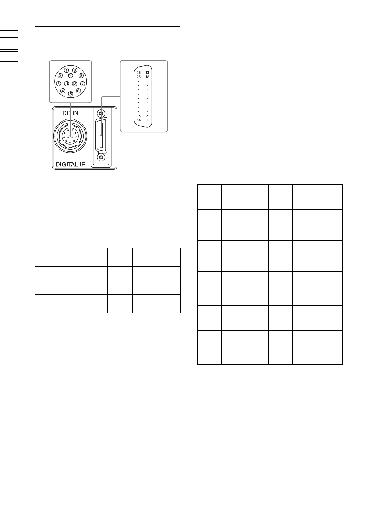
Rear
e DC IN (DC power input) connector (12-pin)
Overview
65
f DIGITAL IF (Interface) connector (26-pin mini connector)
e DC IN (DC power input) connector (12-pin)
You can connect a camera cable CCXC-12P05N etc. to
input the +12 V DC power supply. The pin configuration
of this connector is as follows. You can operate the
camera without using this connector when using a
PoCL-compatible camera module interface board.
For details on the pin arrangement, see the following
table.
Pin No. Signal Pin No. Signal
1 Ground 7 NC
2 +12 V DC 8 Ground
3 Ground 9 NC
4 NC 10 Signal output
5 Ground 11 Triger pulse input
6 NC 12 Ground
*
* Signal output from the Tenth pin of 12 pins
connector
You can select one of the following signals according
to the setting.
Ground / DVAL output / Exposure pules output
The default setting in the factory is Ground.
Pin No. Signal Pin No. Signal
1 Power supply or
2 X0– output
3 X1– output
4 X2– output
5 XCLK– output
6 X3– output
7 SerTC+ (Signal) 20 SerTC– (Signal)
8 SerTFG– (Signal) 21 SerTFG+ (Signal)
9 TRIG– input
10 NC 23 NC
11 NC 24 NC
12 NC 25 NC
13 INNER_SHIELD
Ground
(Signal)
(Signal)
(Signal)
(Signal)
(Signal)
(Signal)
(Ground)
*
14 INNER_SHIELD
(Ground)
15 X0+ output (Signal)
16 X1+ output (Signal)
17 X2+ output (Signal)
18 XCLK+ output
(Signal)
19 X3+ output (Signal)
22 TRIG+ input
(Signal)
26 Power supply or
Ground
*
f DIGITAL IF (Interface) connector (26-pin mini
conector)
Camera Link Base Configuration:
You can connect a Camera Link cable to this connector
to control a camera module from a host device utilizing
the serial communication protocol while outputting a
video signal from the camera module. If you use a
camera module interface board with support for PoCL,
you can also supply power from this connecter. You can
input the external trigger signal via the 26-pin mini
connector and operate a camera module in the external
trigger mode.
The following table shows the relation between the pin
numbers of the DIGITAL IF connector and the input/
output signals and the like.
8
Location and Function of Parts and Operation
* About the 1st pin and 26th pin of the 26-pin mini
connector
The connection differs depending on the type of
camera module interface board you use.
In the case of PoCL support:
Both the 1st pin and 26th pin are
POWER (power supply)
In the case of non-PoCL support:
Both the 1st pin and 26th pin are
INNER_SHIELD (Ground)
Note
When you operate a camera module by inputting an
external trigger signal via the 26-pin mini connector,
make sure to input external trigger signals that meet the
following specifications to both the two pins.
Specifications for the External Trigger Signal
Amplitude: LVDS using a 3.3 volt IC
Connections: Input a TRIG (–) signal to the 9th
pin.
Input a TRIG (+) signal to the 22nd
pin.
Polarity: Positive
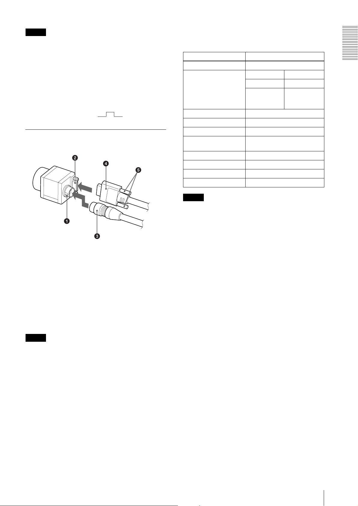
Connecting the cables
DIGITAL IF connector
Camera Link cable
Fastening
screws
Refer to “Camera Control Commands” on page 33 for
details on how to send a command, the commands, and
their parameters.
Control functions Description
Operating mode Normal/Trigger
Shutter speed Normal 2 to 1/10,000 s
Trigger edge 2 to 1/10,000 s
Trigger pulse
width
Gain 0 to +18 dB
Partial Scan OFF/ON
Gamma control OFF/ON (Mode 1 to 5)
External trigger input 26 pin mini connector/12 pin
connector
Video output switch 8 bits/10 bits/12 bits
Binning OFF/ON
Binarization OFF/ON
3×3 filter OFF/ON (manual or preset)
Note
Setting by
trigger pulse
width
Overview
DC IN
connector
Camera cable
Connect the camera cable to the DC IN connector and
the Camera Link cable to the DIGITAL IF cable
respectively. If you use a camera module interface board
with support for PoCL, you can operate the camera even
if you do not connect the camera cable to the DC IN
connector. When you connect the Camera Link cable,
turn the two fastening screws on the connector to secure
the cable tightly.
Connect the other end of the camera cable to the DC700/700CE and the other end of the Camera Link cable
to the camera module interface board.
Note
When using the camera with a PoCL connection, make
sure you connect a PoCL compatible cable. Connecting
a cable that is not compatible with PoCL (non-PoCL)
may cause a malfunction of the camera or camera
module interface board.
Make sure to supply power to the camera module and
confirm that the camera module is operating before
inputting a trigger signal. If you input trigger signal to a
camera module without the power supplied, this may
cause a malfunction of the camera module.
Controlling the camera from the host
device
You can control the camera from host device such as a
computer. The following table shows the control
functions.
You can send a command corresponding to the control
items, with parameters for the desired settings, if
necessary, from the host device to control the camera.
Location and Function of Parts and Operation
9
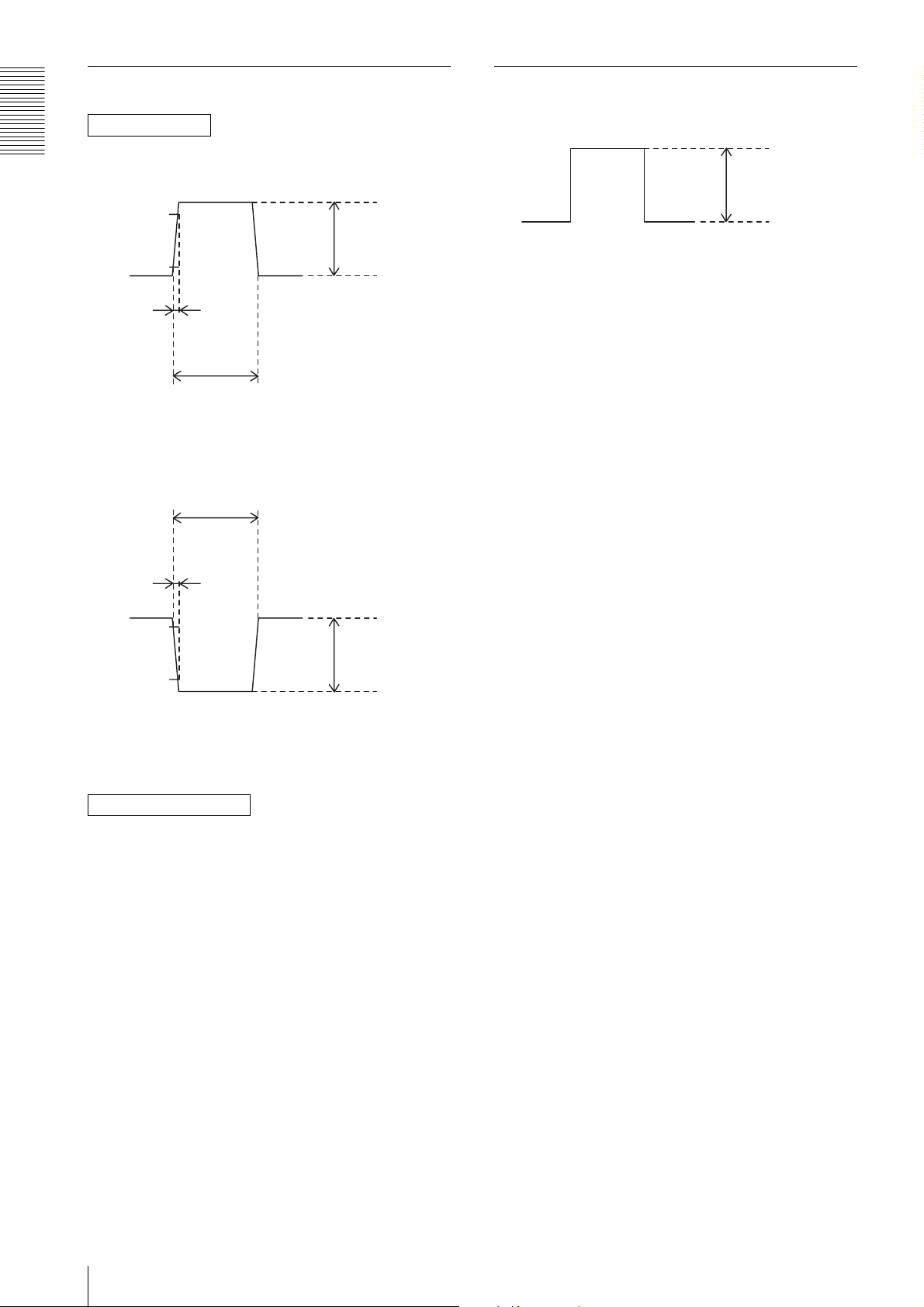
Trigger signal specifications
DVAL/Exposure output specific (only DC IN terminal)
DC IN terminal
4 - 5 V
Overview
When trigger pulse polarity is positive
90%
10%
Rising time
2.0 µs or less
Width
10.0 µs - 2 s
When trigger pulse polarity is negative
10.0 µs - 2 s
2 - 5 V
Amplitude
0 - 0.6 V
0 V
Stated in the voltage of when terminating at more than
10 k ohms
Dropping time
2.0 µs or less
10%
90%
Width
10.0 µs - 2 s
2 - 5 V
Amplitude
0 - 0.6 V
Input impedance: Stated in the voltage determined at
more than 10 k ohms
DIGITAL IF terminal
Convert the signal which meets the specifications above
into LVDS format (3.3 V power drive IC output), and
inputs the converted signal.
Note that the signal level cannot be recognized correctly
by the camera if it does not meet the following
conditions.
H level: 1.5 V to 1.7 V
L level: 0.8 V to 1.0 V
10
Location and Function of Parts and Operation

Functions
1. Compatibility with
previous model
XCL-5005
The XCL-U100 is a 2-megapixel digital video camera
model that is based on the XCL-5005 and supports the
PoCL standard.
Some of the control commands used on the XCL-U100
differ from those on the XCL-5005. The main
differences are as follows.
Command Command string Difference from XCL-5005
Gain setting (dB) GAIN-STEP a
Gain setting (step) GAIN-FINE a
Pedestal adjustment PEDESTAL a
Shutter speed SHUTTER f Parameters are different.
Trigger mode TRG-MODE a
External trigger polarity setting TRG-POL a
External trigger overlap TRG-OVLP a
External trigger delay TRG-DELAY f Added command.
Digital gain DGAIN f Parameters are different.
Digital pedestal DPEDESTAL f Parameters are different.
Digital clamp DCLAMP f Parameters are different.
Binarize setting BINARIZE a
Gamma mode setting GAMMA-MODE f Parameters are different.
LUT value setting GAMMA a
Filter mode FILTER-MODE a
Filter setting FILTER a
Binning setting BINNING a
Partial scan setting PARTIAL f Parameters are different.
Horizontal partial scan setting HPARTIAL f Parameters are different.
External trigger signal input EXTTRG a
Grayscale chart output GRAYSCALE a
DC IN connector signal output setting WEN-STRB a
Image output data depth BIT-DEPTH × The command and parameters are different.
(Can be configured with IMG-WIZE.)
Serial communication speed setting BRATE a
Initialization of settings INIT a
Save setting values SAVE a
Load setting values LOAD a
Setting value accession RMEM a
Version display VERSION a
Help display HELP a
Functions
For details on commands and their parameters, see the
“Camera Control Commands” on page 33.
1. Compatibility with previous model XCL-5005
11
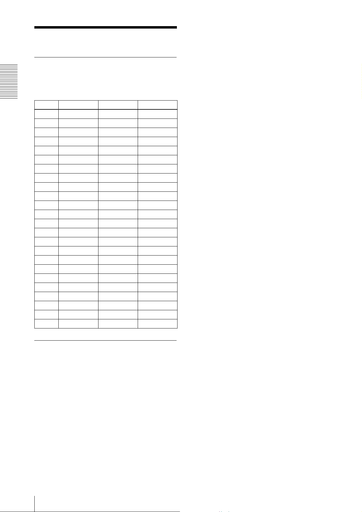
2. Video output format
2.1. Port assignment
The following table shows the assignment for the three
ports (A, B, and C) and the video signal (D1) as defined
in the base configuration.
Functions
Port 8 bits 10 bits 12 bits
Port A0 D1 [0] D1 [0] D1 [0]
Port A1 D1 [1] D1 [1] D1 [1]
Port A2 D1 [2] D1 [2] D1 [2]
Port A3 D1 [3] D1 [3] D1 [3]
Port A4 D1 [4] D1 [4] D1 [4]
Port A5 D1 [5] D1 [5] D1 [5]
Port A6 D1 [6] D1 [6] D1 [6]
Port A7 D1 [7] D1 [7] D1 [7]
Port B0 D1 [8] D1 [8]
Port B1 D1 [9] D1 [9]
Port B2 D1 [10]
Port B3 D1 [11]
Port B4
Port B5
Port B6
Port B7
Port C0
Port C1
Port C2
Port C3
Port C4
Port C5
Port C6
Port C7
2.2. Output data size
The XCL-U100 has an effective resolution of 1600 ×
1200 (horizontal/vertical). The effective clock for
standard LVAL is 1600, and the effective lines for FVAL
is 1200.
12
2. Video output format
3. Camera mode
3.1. Horizontal timing
The horizontal timing is common for all modes. The
XCL-U100 is provided with a horizontal partial scan
function (HPARTIAL) that is capable of changing the
length of the Hi section of the LVAL signal. Configuring
a minimum of 128 columns anywhere between columns
0 and 1599 of the horizontal effective video area enables
a reduction in the number of columns imported on the
host device (computer) side. The frame rate does not
change even if HPARTIAL is set to ON.
Horizontal timing: Common for each mode
HPARTIAL OFF (Normal Mode)
LVA L
DVAL
CL
Functions
Video output
(pixels)
HPARTIAL ON
Example: HPARTIAL 1 20 819
LVA L
DVAL
CL
Video output
(pixels)
123 1598 159916001600 1
1600 CL320 CL
(number of pixels displayed)
121 820 16001600 1
Starting pixel
for display
Number of columns read
800 CL
1600 CL320 CL
Ending pixel
for display
800 columns
780 CL20 CL
Effective pixel area
(LVAL = “H”)
1600 pixels
1H = 53.333 µs
1 CL = 27.777 ns
Note
When horizontal partial scan is set to ON, set the line
number for the effective video area.
Set the number of columns to read to a number between
128 and 1600. An error will occur if the number of
columns configured is not within this range.
3. Camera mode
13
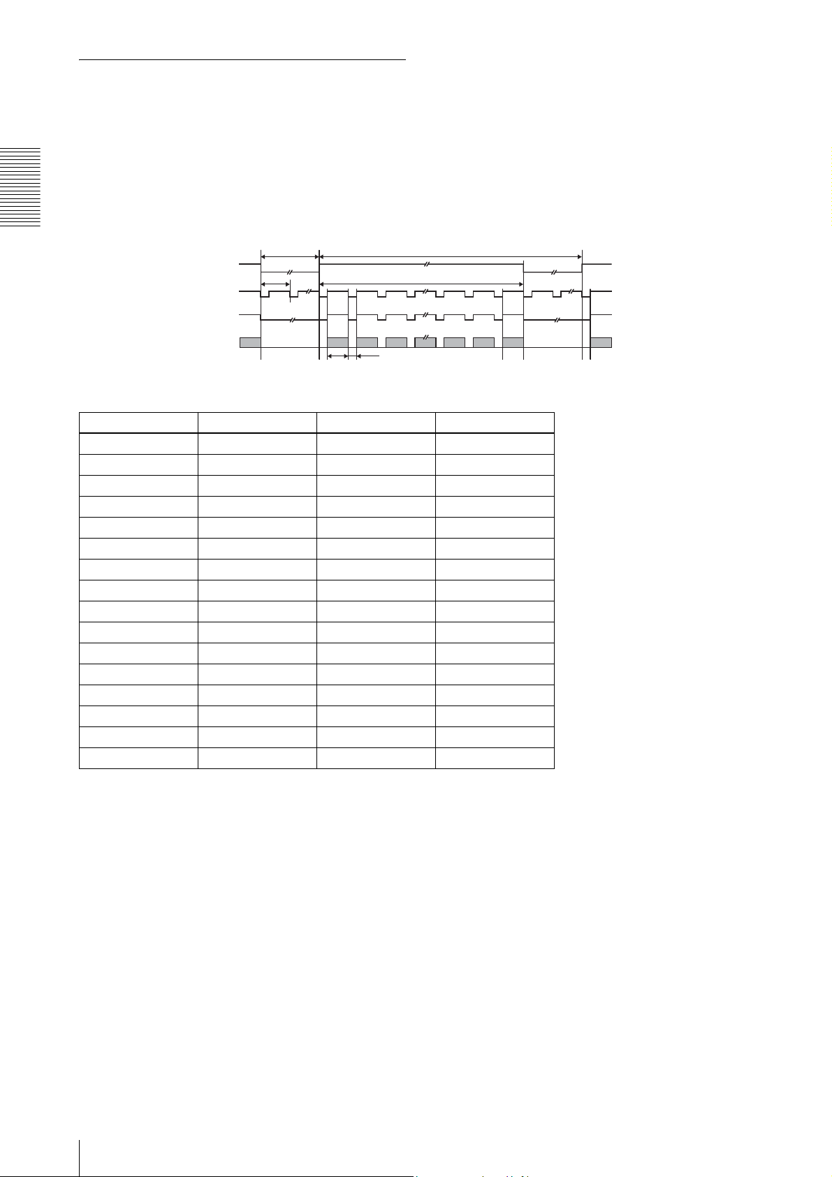
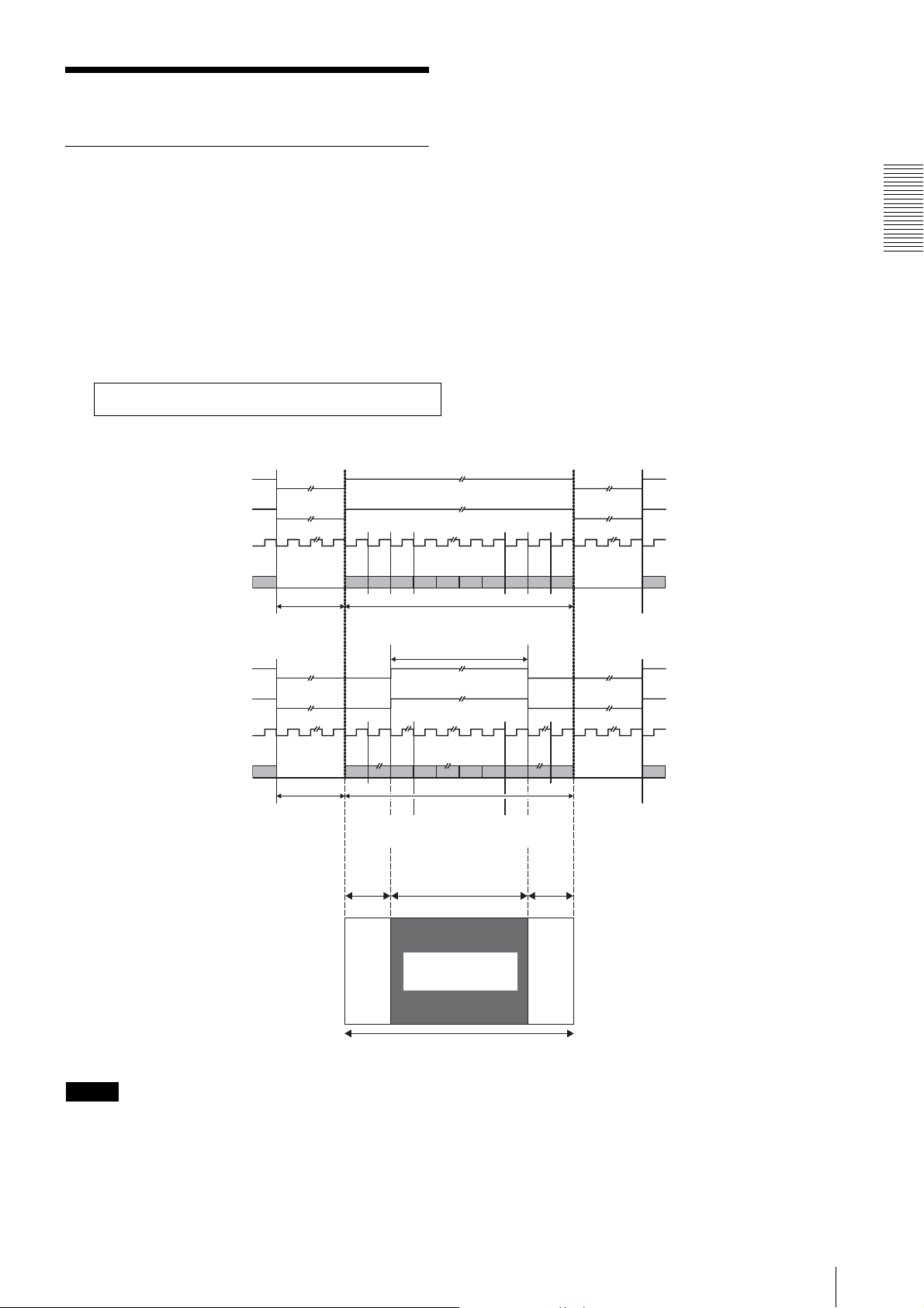
3.2. Vertical timing
The vertical timing differs between each mode.
3.2.1. Normal mode
This mode is for outputting the individual video signals
of all pixels as continuous video at 15 frames per second.
Functions
FVAL
LVA L
DVAL
T3 T1
1 H 1200 H
Video output
(lines)
12 1199 12001200 1
1600 CL 320 CL
Shutter T1 T3 Frame rate
2 s 2 s 36302 H 0.5 fps
1 s 1 s 17552 H 1 fps
1/2 s 500 ms 8177 H 2 fps
1/7.5 s 133.34 ms 1302 H 7.5 fps
1/15 s (OFF) 66.8 ms 53 H 14.97 fps
1/30 s 66.8 ms 53 H 14.97 fps
1/60 s 66.8 ms 53 H 14.97 fps
1/100 s 66.8 ms 53 H 14.97 fps
1/120 s 66.8 ms 53 H 14.97 fps
1/250 s 66.8 ms 53 H 14.97 fps
1/500 s 66.8 ms 53 H 14.97 fps
1/1,000 s 66.8 ms 53 H 14.97 fps
1/2,000 s 66.8 ms 53 H 14.97 fps
1/5,000 s 66.8 ms 53 H 14.97 fps
1/10,000 s 66.8 ms 53 H 14.97 fps
Arbitrary ≥ 66.8 ms ≥ 53 H *1
*1 Frame rate = 1 / shutter speed
However, the maximum frame rate is 14.97 fps.
1 H = 53.333 µs
1H = 53.333 µs
1 CL = 27.777 ns
14
3. Camera mode
 Loading...