

Sony XCL-SG510C, XCL-SG510 Technical Manual

Digital Video
Camera Module
C-293-100-11 (1)
Technical Manual
XCL-SG510/SG510C
© 2016 Sony Corporation

Table of Contents
Overview
Features ...................................................................3
Phenomena Specific to Image Sensors .................4
System Components ...............................................5
Connection ..............................................................6
Location and Function of Parts and
Operation ................................................................7
Front/Top/Bottom ...............................................7
Using a tripod .....................................................7
Rear .....................................................................8
Connecting the cables .........................................8
When mounting the camera ..............................10
Connections
Communication Setting .......................................11
Camera link output settings ................................12
Data Order ............................................................13
1tap ...................................................................13
2tap ...................................................................13
ntap ...................................................................14
Port assignment .................................................14
Color pixel array ...............................................14
Trigger Signal Input ............................................15
Trigger signal polarity ......................................15
GPIO Connector ..................................................16
Functions
Partial Scan ..........................................................19
Multi ROI .............................................................20
Binning ..................................................................21
Output Bit Length ................................................21
Image flip ..............................................................21
Gain .......................................................................21
Manual gain ......................................................21
Auto gain (AGC) ..............................................21
Area gain ...........................................................22
Shutter (Exposure) ...............................................22
Configuring the setting .....................................22
Auto exposure (AE) ..........................................22
Combination of Continuous AGC and Continuous
AE ..........................................................................22
Trigger Control ....................................................23
Free run/trigger mode .......................................23
Special trigger ...................................................24
Trigger source ...................................................25
Trigger inhibition ..............................................25
Trigger delay .....................................................26
Trigger counter .................................................26
Frame counter ...................................................26
Trigger range limit ............................................26
Frame Rate ........................................................... 27
Auto frame rate ................................................ 27
Specifying frame rate ....................................... 27
Displaying frame rate ....................................... 27
Fastest frame rate for partial scanning ............. 28
White Balance ...................................................... 31
LUT ....................................................................... 31
Binarization ...................................................... 31
5-point interpolation ......................................... 31
17-point interpolation ....................................... 32
Arbitrary setting ............................................... 32
Save LUT ......................................................... 32
3 × 3 filter ............................................................. 32
Test Chart Output ............................................... 33
GPIO ..................................................................... 33
GPI ................................................................... 33
GPO .................................................................. 33
Sensor Readout (Sensor Output) ...................... 35
Pulse Train Generator ......................................... 35
Status LED ........................................................... 35
Temperature Readout Function ......................... 36
Defect Correction ................................................. 36
Shading Correction .............................................37
Area exposure ...................................................... 39
Wide dynamic range ........................................... 39
Frame accumulation ............................................40
User Set .................................................................40
User set name ................................................... 41
User set memory .............................................. 41
Free Memory ........................................................ 41
User ID .................................................................. 41
Saving and Startup .............................................. 41
Initializing ............................................................ 41
Camera Information ........................................... 41
Help Command ....................................................42
Echo off .................................................................42
Restart .................................................................. 42
Error information acquisition ............................ 42
Exclusion function ............................................... 43
Camera Control Commands
Command Form ................................................... 44
Command Input and Response .......................... 44
Command List ..................................................... 45
Specifications
Specifications ........................................................ 50
Timing Chart ....................................................... 51
Horizontal timing ............................................. 51
Vertical timing .................................................. 52
Trigger latency/Exporure time ......................... 52
Spectral Sensitivity Characteristics (Typical
Values) .................................................................. 53
Dimensions ........................................................... 54
2

Overview
This unit is a digital video camera module that outputs
digital images utilizing LVDS via the DIGITAL IF
connector.
Features
DIGITAL IF connector
Equipped with a Camera Link standard mini connector.
The unit can output a detailed and high speed digital
image.
Switching an Output Bit Length
You can select 8-bit output, 10-bit output, 12-bit output,
or 16-bit output.
Binning (Monochrome camera only)
Sensitivity can be doubled by combining two pixels
aligned vertically, you can achieve a standard output
frame rate between 1.8x and 2x. Sensitivity can be
doubled by combining two pixels align horizontally.
You can set horizontal and vertical binning at the same
time.
Defect correction
The unit includes a function to reduce sensor defects,
and can be set to ON or OFF.
High image quality
2/3 type 5.07 Megapixel CMOS image sensors with a
global shutter function (Monochrome/Color)
Various settings
Sending a command from the host device allows various
settings, including the following.
•Gain
•Shutter
• Partial scan
• Trigger control
• LUT (Look Up Table)
• Output: 8/10/12/16-bit
• Defect correction
• Shading correction
Electronic shutter function
Set anywhere from 1/100,000 sec to 60 sec in 1 µs
increments.
External trigger shutter function
By synchronizing with an external trigger signal, any
shutter timing can be used.
Partial scan
The camera module can limit the number of video
output lines to achieve high frame rates, enabling highspeed image processing.
Shading correction
The unit includes a function to correct shading, resulting
from a light source or a particular lens, and can be set to
ON or OFF.
Multi ROI function
Optional 8 rectangular areas from the effective pixel
area can be read out. Reading out only the necessary part
shortens the time to read out.
Area gain function
You can set the individual digital gain to 16 optional
rectangular areas. In the case that multiple rectangular
areas overlap, the gain value with the smaller area
number will have priority.
Frame accumulation function
Calculates the average of multiple frames. It can reduce
image noise or differences. Specifies the number of
frames to average with the parameter.
Wide dynamic range function
Enables tone restoration in bright and dark parts without
the tone in scenes with strong contrast.
Area explosion function
Two types of exposure times can be set to the valid pixel
area and 16 optional rectangular areas.
Body fixing
The screw holes to install the camera module are located
under the front panel (the image sensor reference plane).
Installing the camera module on the front panel
minimizes deviation of the optical axis.
LUT (Look Up Table)
You can switch to OFF or ON. When set to ON, you can
select from five preset values, such as inversion,
binarization, any of five-point approximation, etc.
Note
If intense light is input to the image, the peripheral areas
of the video image may be affected. In such a situation,
adjust the amount of light using the iris.
3

Phenomena Specific to Image Sensors
Note
The following phenomena that may occur in images are
specific to image sensors.
They do not indicate a malfunction.
White flecks
Although the image sensors are produced with highprecision technologies, fine white flecks may be
generated on the screen in rare cases, caused by cosmic
rays, etc.
This is related to the principle of image sensors and is
not a malfunction.
The white flecks especially tend to be seen in the
following cases:
• when operating at a high environmental temperature
• when you have raised the gain (sensitivity)
• when using the slow shutter
Aliasing
When fine patterns, stripes, or lines are shot, they may
appear jagged or flicker.
4
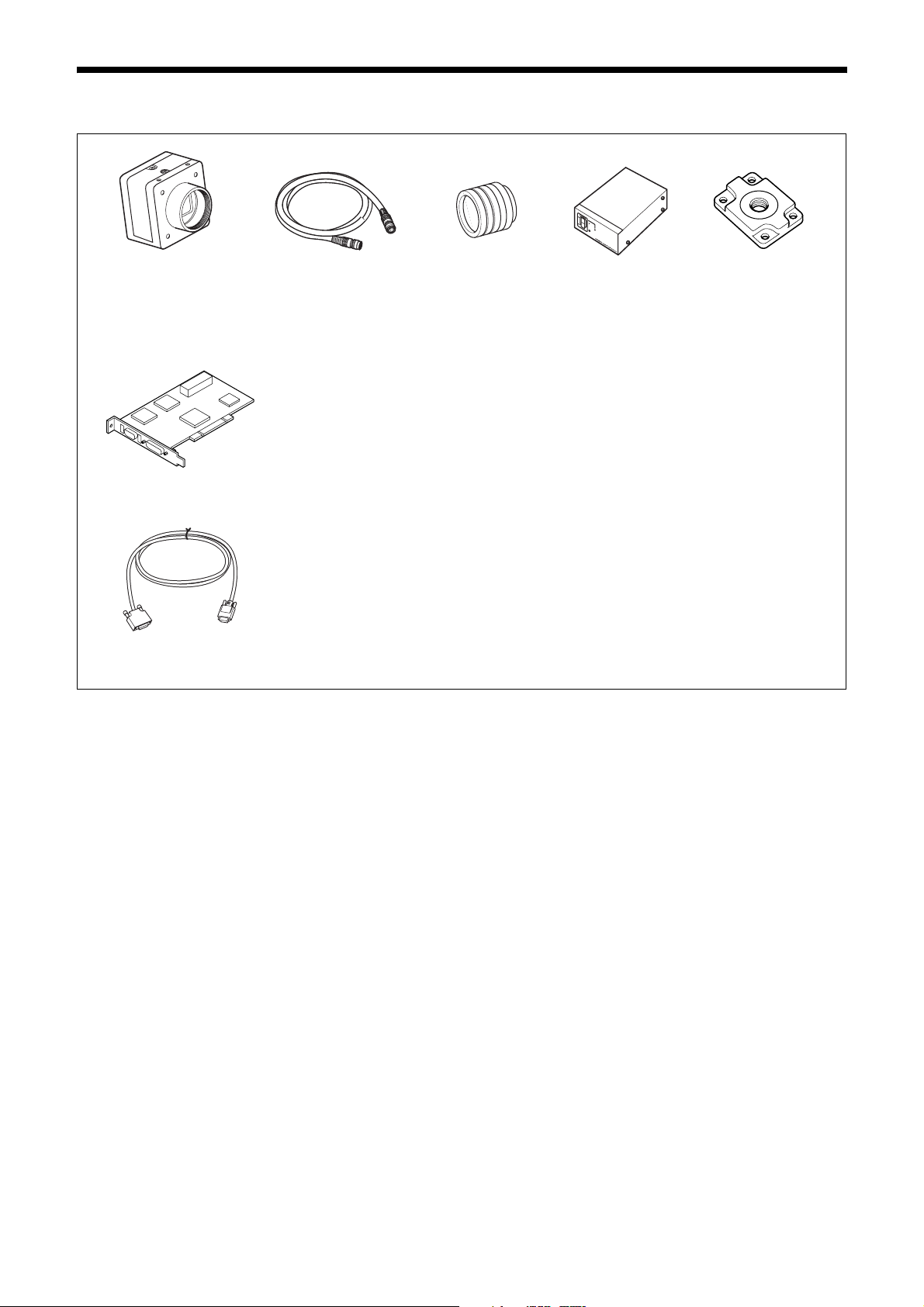
System Components
Video Camera Module Camera cable
Camera module interface
board
Camera Link cable
(Sony Camera-compatible)
CCXC-12P02N (2 m, 6.6 ft)
CCXC-12P05N (5 m, 16.4 ft)
CCXC-12P10N (10 m, 32.8 ft)
CCXC-12P25N (25 m, 82 ft)
Install the board in a PCI bus slot in devices such as a computer. Select a commercially
available interface board compatible with the Camera Link feature. You can use either a board
that supports PoCL, or one that does not.
Use boards that support dual-power supply when you use the camera link configuration in
Medium, Full, or 80 bit with powered via PoCL.
Due to the performance of the board, the frame rate may become low according to lack of
processing capacity. To have this product output frames at the highest speed, use a board
corresponding to PCI-Express.
Performance may also be dependent on the host device (e.g., Computer), so consult the
dealer if images are not displayed properly.
This cable connects to the DIGITAL IF connector on the rear panel of the camera module.
Image/control signals are transmitted via this cable.
If there is support for PoCL, power is also supplied at the same time.
If you use a camera module interface board with support for PoCL, be sure to use a camera
link cable with support for PoCL. Use appropriate camera link cables for each specification
when you use the camera link configuration in Medium, Full, or 80 bit. Select a proper cable
as the maximum usable length of a cable differs due to the attribute of each cable.
Spotted noise may appear in a specific brightness in the window according to the attribute of
the cable. If this noise is an obstacle, shorten the cable.
C-mount lens
Use a lens appropriate
for the pixel count of
the camera.
Camera adaptor
DC-700/700CE
Tripod adaptor
VCT-333I (Insulated type)
5
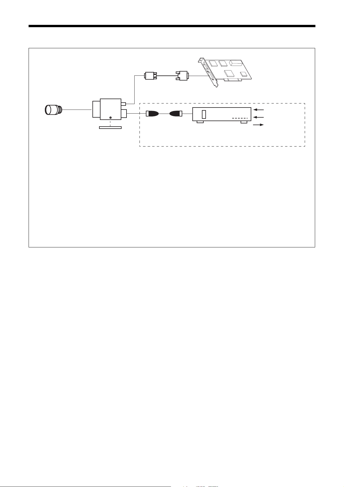
Connection
Camera Link cable
Camera module
C-mount lens
Camera cable
CCXC-12P02N
Tripod adaptor
VCT-333I
Power supply
You can supply power to the camera module using the following methods.
Using the DIGITAL IF connector
As this unit adopts camera link PoCL standards, both the supplying power and camera control/image output are supported with
single or double camera link cable(s) using a camera link PoCL standard compatible camera link cable and image input board for
the camera.
Heat dissipation is required depending on the usage environment.
For heat dissipation, refer to When mounting the camera (see page 10).
CCXC-12P05N
CCXC-12P10N
CCXC-12P25N
* If the camera module interface board for the camera supports PoCL, the
camera can be operated even if the items within the dashed line are not
connected.
Camera module interface board
Camera adaptor
DC-700/700CE
AC
TRIG
Internal signal
output
Using the DC IN connector
You can supply power via the DC IN connector using the power adapter.
Use DC-700/700CE which is the stable power source free from ripple or noise.
6
Location and Function of Parts and Operation
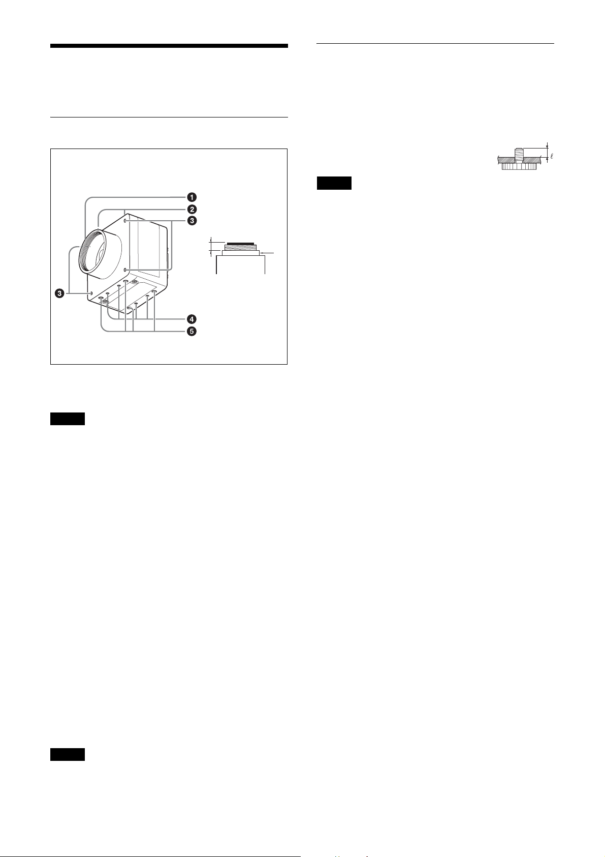
Front/Top/Bottom
Using a tripod
To use the tripod, install the tripod adaptor VCT-333I
(not supplied) on the camera module.
Use a tripod screw with a protrusion (4) extending from
the installation surface, as follows, and tighten it, using
a screwdriver. Be sure that the protrusion (4) does not
exceed 5.5 mm (0.22 in.) in length.
Length 4.5 to 5.5 mm
Length 0.18 to 0.22 inches
Note
If you install a tripod adapter (not supplied), use the
screws provided.
a
a Lens mount (C-mount)
Attach any C-mount lens or other optical equipment.
Note
Use a C-mount lens with a protrusion (a) extending from
the lens mount face (b) of 10 mm or less.
When you use the camera with the lens attached, the
resolution of the image output from the camera may
differ according to the performance of the lens. Note it
when you select a lens.
The performance of a lens may change according to the
aperture level.
If the resolution is not enough, adjust the aperture level.
b
b Guide screw holes (Top)
c LED light guide screw hole (Front)
Screw hole to guide LED light.
Prepare appropriate adopter according to the LED light
to guide.
d Guide screw holes / Tripod screw holes (Bottom)
When using a tripod, use these four screw holes to attach
a VCT-333I tripod adaptor.
e Reference screw holes (Bottom)
These precision screw holes are for locking the camera
module. Locking the camera module into these holes
secures the optical axis alignment.
Note
Refer to the outer dimensions on page 54 about the
guide hole and the position and size of standard hole.
7
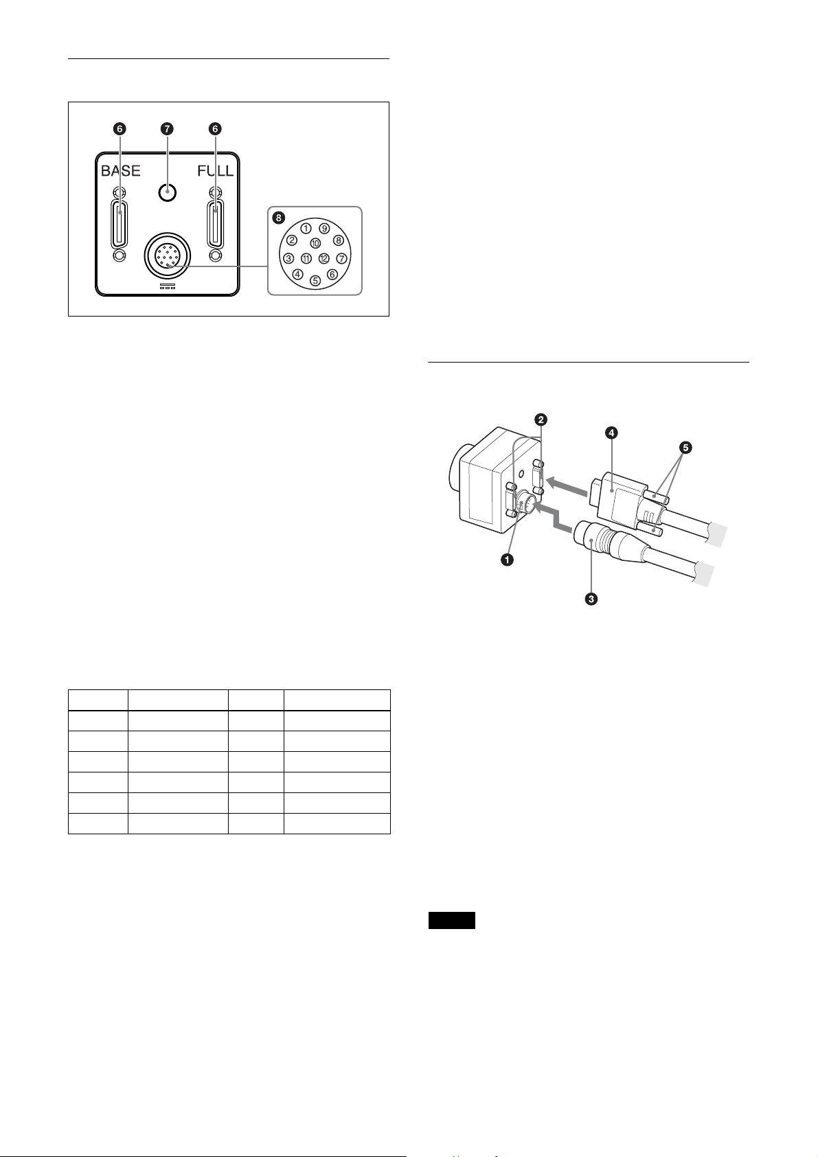
Rear
f DIGITAL IF (Interface) connector (26-pin)
You can connect a Camera Link cable to this connector
to control a camera module from a host device utilizing
the serial communication protocol while outputting a
video signal from the camera module. If you use a
camera module interface board with support for PoCL,
you can also supply power from this connecter. The
camera module can also be actuated in external trigger
mode by an inputting external trigger signal from this
DIGITAL IF terminal.
Signal output
Pins 4, 6, 7 and 9 (GPI1/2/3/4) allow you to select GPO
from the exposure signal, strobe control signal, Hi/Low
fixed value, etc.
When using 2 systems for GPO (ISO):
– GPO4 (ISO+) (pin 9) and GPO4 (ISO–) (pins 3 and
12) are used.
– GPO2 (ISO+) (pin 6) and GPO2 (ISO–) (pin 5) are
used.
When using 2 systems for GPO:
– GPO1 (pin 4*) and Ground (pin 1) are used.
– GPO3 (pin 7*) and Ground (pin 1) are used.
* The initial value of pins 4 and 7 is GPI. Switch to GPO
output by external command.
Connecting the cables
g Status LED (Green)
Displays the unit status.
For details, refer to “Status LED” (see page 35).
h DC IN (DC power input) connector (12-pin)
You can connect a CCXC-12P05N camera cable to input
the +12 V DC power supply. If you use a camera module
interface board with support for PoCL, you can operate
the camera without using this connector. The pin
configuration of this connector is as follows.
Pin No. Signal Pin.No. Signal
1 Ground 7 GPI3/GPO3
2 DC+12V 8 GPI4 (ISO–)
3 GPO4 (ISO–) 9 GPO4 (ISO+)
4 GPI1/GPO1 10 GPI4 (ISO+)
5 GPO2 (ISO–) 11 GPI2
6 GPO2 (ISO+) 12 GPO4 (ISO–)
Power input
Pin 1 (Ground) and pin 2 (DC +12V) are used.
Signal input
Pins 4, 7, 10 and 11 (GPO1/3/4/2) are used for GPI input
or trigger input.
When using 1 system for GPI (ISO):
– GPI4 (ISO+) (pin 10) and GPI4 (ISO–) (pin 8) are
used.
When using 2 systems for GPI:
– GPI1 (pin 4*) and Ground (pin 1) are used.
– GPI3 (pin 7*) and Ground (pin 1) are used.
Connect the camera cable (c) to the DC IN connector
(a) and the Camera Link cable (d) to the DIGITAL IF
connector (b) respectively. If you use a camera module
interface board with support for PoCL, you can operate
the camera even if you do not connect the camera cable
to the DC IN connector. When you connect the Camera
Link cable, turn the two fastening screws (e) on the
connector to secure the cable tightly.
Connect the other end of the camera cable to the DC700/700CE and the other end of the Camera Link cable
to the camera module interface board.
When using the Camera link configuration in Base
mode, connect the Camera Link cable to BASE of the
DIGITAL IF connector.
Connect cables to the BASE and FULL terminals when
you use the camera link configuration in Medium, Full,
or 80 bit.
Notes
• Please be careful with the points described below.
These may be the cause of camera failure or image
input board.
– Connect or disconnect camera cables or camera link
cables while the power is not supplied.
– Supply power after confirming each cable is firmly
connected.
8

– Do not supply power from both camera cable and
camera link cable simultaneously.
– If you use the camera with PoCL connection, make
sure to connect a cable that supports PoCL.
• When power is supplied via the single camera link
cable, if the Camera link configuration is launched
with Medium, Full, or 80 bit settings, video will not be
output from the camera.
If the Camera link configuration is launched in Base
setting, functions in below will be restricted.
– Area exposure (page 39)
– Wide dynamic range (page 39)
– Frame accumulation (page 40)
Controlling the camera from the host
device
You can control the camera from host device such as a
computer.
You can send a command corresponding to the control
items, with parameters for the desired settings, if
necessary, from the host device to control the camera.
Refer to “Camera Control Commands” on page 44 for
details on how to send a command and its parameter.
Note
Make sure to supply power to the camera module and
confirm that the camera module is operating before
inputting a trigger signal. If you input trigger signal to a
camera module without the power supplied, this may
cause a malfunction of the camera module.
9
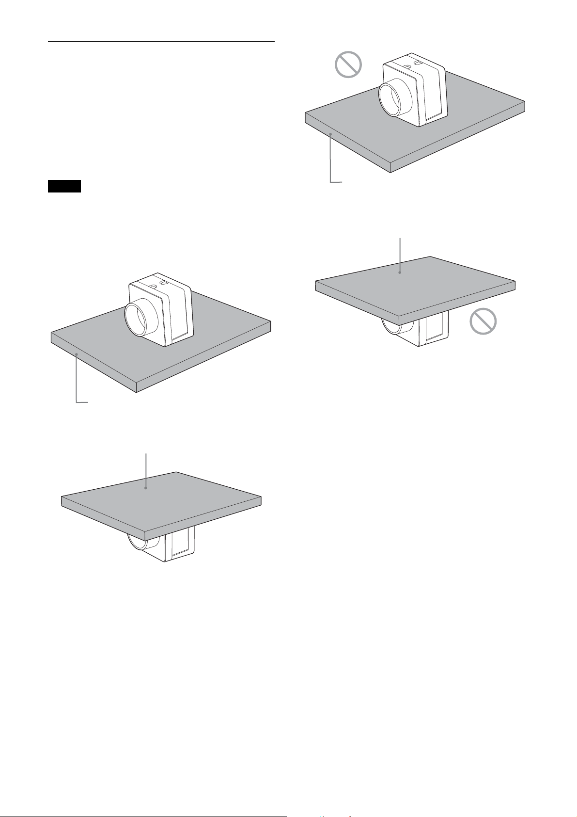
When mounting the camera
When the value read from temperature sensor is above
78 °C (173 °F), heat dissipation is required.
To promote heat dissipation from the unit and maintain
performance, mount the camera to a metallic heat
dissipation plate.
Dimension of the heat dissipation plate: 160 mm ×
130 mm × 5 mm or more (Thermal conductivity:
16.3 W/m·K or more)
Notes
• When mounting the camera to the heat dissipation
plate, secure the camera tightly by using the reference
screw holes (see page 7) and screws.
• Do not mount the camera to a plate made of a material
such as wood or resin that prevents heat dissipation.
Metallic heat dissipation plate
Metallic heat dissipation plate
Plate that prevents heat dissipation
(made of wood, resin, etc.)
Plate that prevents heat dissipation
(made of wood, resin, etc.)
10
Connections
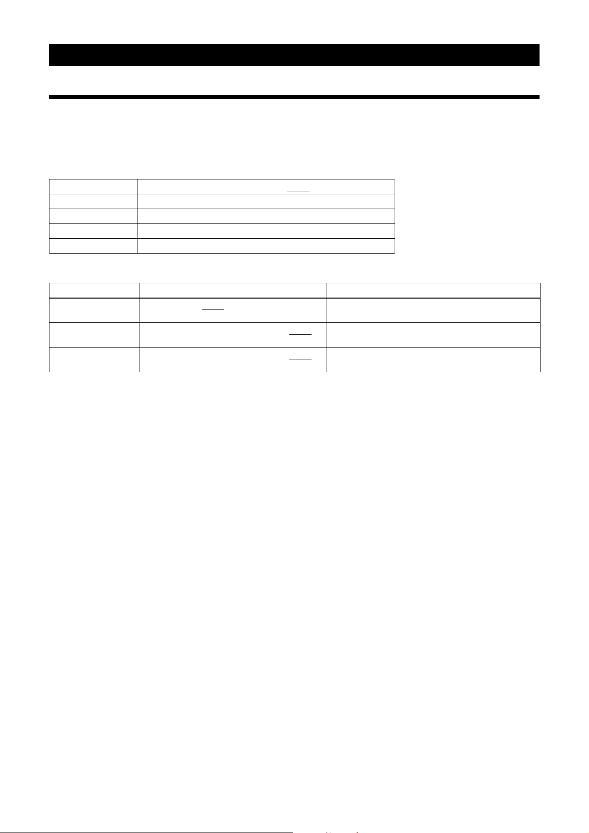
Communication Setting
Uses serial ports assigned to the camera link board. Communication settings are shown in the table below. Echo back
is performed for input commands.
Echo back can be set OFF to accelerate command responses. Commands are not case sensitive.
Baud rate 921600/460800/230400/115200/57600/38400/19200/14400/9600
Data bit 8
Parity None
Stop bit 1
Flow control None
Default values are underlined. (same applies hereinafter)
Command Parameter
BAUDRATE 115200/57600/38400
BAUDRATE-TMP 921600/460800/230400/115200/57600/38400
19200/14400/9600
BAUDRATE-SAVE 921600/460800/230400/115200/57600/38400
19200/14400/9600
/19200/14400/9600 Settings are saved in the camera and will be enabled
after restart.
/
Settings will be implemented immediately, but not
saved in the camera.
/
Settings are saved in the camera and will be enabled
after restart.
When you increase the baud rate, save them using the BAUDRATE-SAVE command after changing the settings
temporarily using the BAUDRATE-TMP command and confirming the communication between PC is enabled.
11
Camera link output settings
Camera link tap can be selected from 1, 2, 3, 4, 8, or 10.
Pixel clock frequency can be selected from 45 MHz, 65 MHz, or 85 MHz.
By turning down the clock frequency, the length of the camera link cable can be extended because of durability
improvement against the attenuation of image signals.
Camera link tap and Pixel lock settings will be saved on the flash memory automatically and enabled after restart.
You don’t have to set each time when launching the application.
Command Parameter
CAMERALINK-TAP 1/2/3/4/8/10 Setting other than provided in left will not work.
BASE-CLOCK 45/65/85 Specify clock frequency [MHz].
Combinations of camera link taps and output bit lengths.
When the camera link tap is set at 8 or 10, the image signal output level is 4 times as high as when set as 1, 2, 3, or 4.
Output Bit Length 8 zzzzzz
10 zz – z ––
12 zz – z ––
16 z*–––––
z Usable function – Not usable function
* To output in 16-bit length, enable wide dynamic range (see page 39).
When wide dynamic range is not enabled, only the top 12-bit will be enabled.
Setting other than provided in left will not work.
CAMERALINK-TAP
1234810
Camera link configuration settings
CAMERALINK-TAP Configuration
1Base
2Base
3Base
4Medium
8Full
10 80bit
12
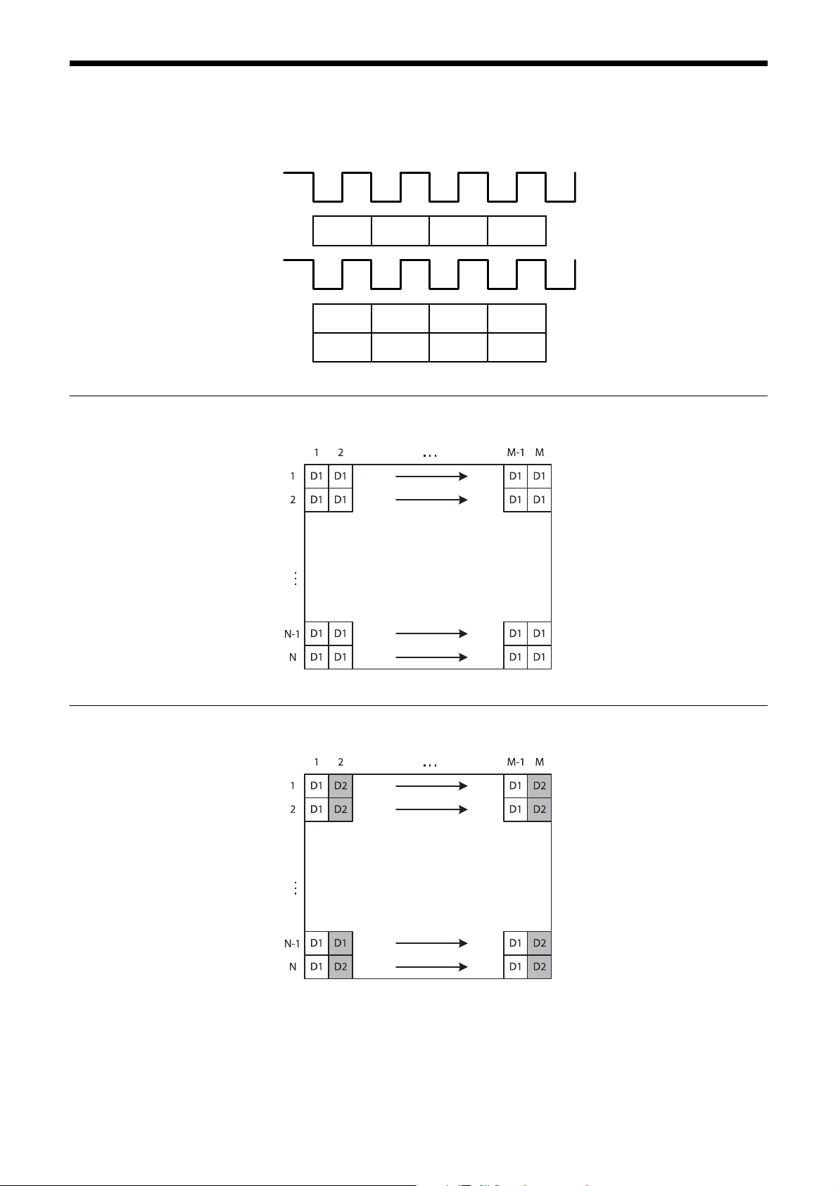
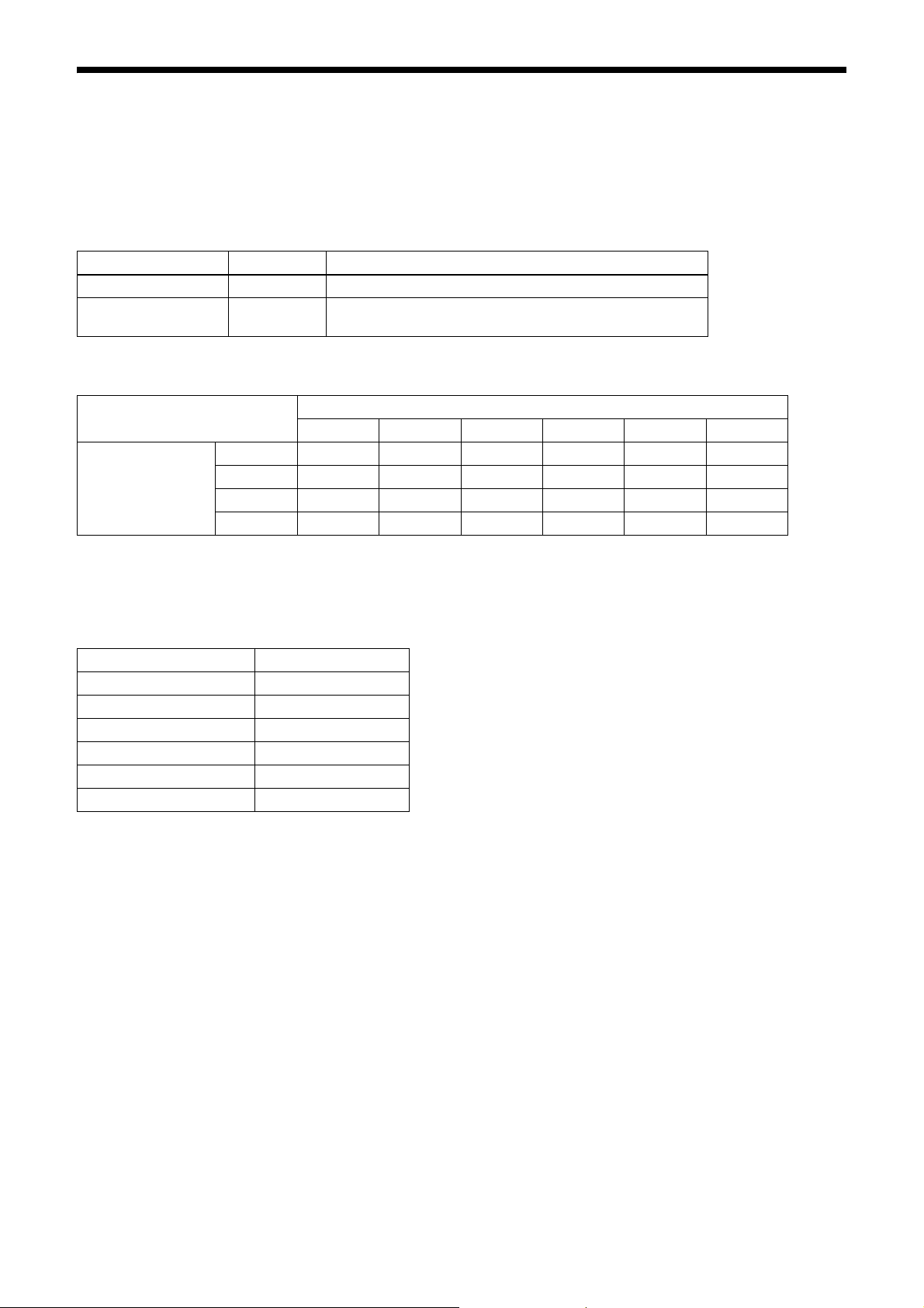
Data Order
Figures below show the data order when an image of M × N pixels is transmitted in 1tap/2tap. Data order on each tap
will be the same for 3, 4, 8, and 10.
STROBE
1tap
1tap
2tap
Video output
STROBE
Video output
D1
D1 D1 D1 D1
D2 D2 D2 D2
D1 D1 D1
M × N pixels
2tap
M × N pixels
13

ntap
M × N pixels
Port assignment
Camera link port allocation to image signal output data of this unit complies with Camera Link V2.0 specifications.
Color pixel array
Signals of all pixels are output sequentially according to the Bayer Array corresponding to the settings of image grip.
Reverse X Reverse Y Location
00
01
10
11
14
Trigger Signal Input
Trigger signals can be input via the 4th, 7th, 10th, 11th pins of the DC IN connector, the CC1, CC2, CC3, CC4 pins of
the Digital IF connector, or the software command. Switchover of the trigger signal can be changed via the TRG-SRC
command.
Command Parameter Trigger signal assigned pin
TRG-SRC 4 DC IN connector 4th pin (GPI1)
7 DC IN connector 7th pin (GPI3)
10 DC IN connector 10th pin (GPI4)
11
101 Digital IF connector 22nd [+]/9th [-] (CC1)
102 Digital IF connector 10th [+]/23rd [-] (CC2)
103 Digital IF connector 24th [+]/11th [-] (CC3)
104 Digital IF connector 12th [+]/25th [-] (CC4)
0 Software command (TRG-SOFT)
20 OR of GPI1/GPI2/GPI3/GPI4
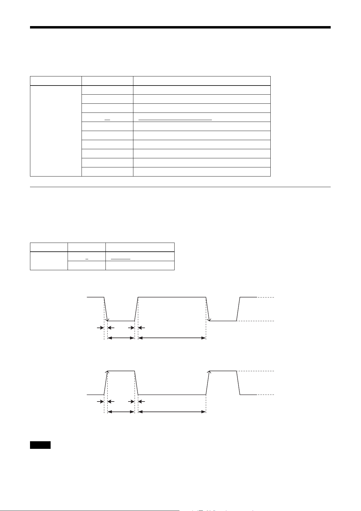
Trigger signal polarity
Positive refers to a trigger signal polarity activated while rising from Low to Hi, or during the Hi interval. Negative refers
to a trigger signal polarity activated while falling from Hi to Low, or during the Low interval. The default value of a
camera is Negative. The GPI connectors 1, 2, and 3 are pulled up on the camera side. When a connector is open, the
trigger signal is at the high level and is logically inactive. Note that when Positive of GPI1, 2 or 3 is selected as a trigger
input, when the terminal is open, the trigger will be activated.
DC IN connector 11th pin (GPI2)
Command Parameter Trigger signal polarity
TRG-POL 0
1 Positive
Negative
DC IN connector specifications
2.0 µs or less
10 µs to 2 s
2.0 µs or less
10 µs to 2 s
2.0 µs or less
1 frame hour or more
Trigger input polarity = Negative
2.0 µs or less
1 frame hour or more
2 to 24 V
0 to 0.4 V
2 to 24 V
0 to 0.4 V
Trigger input polarity = Positive
Note
When inputting a trigger signal to the camera using the DC-700/CE, use DC 5 V or less at the logical high level.
15
Digital IF connector specifications
0.30 to 0.40 V
0.30 to 0.40 V
1.125 to 1.375 V
GND
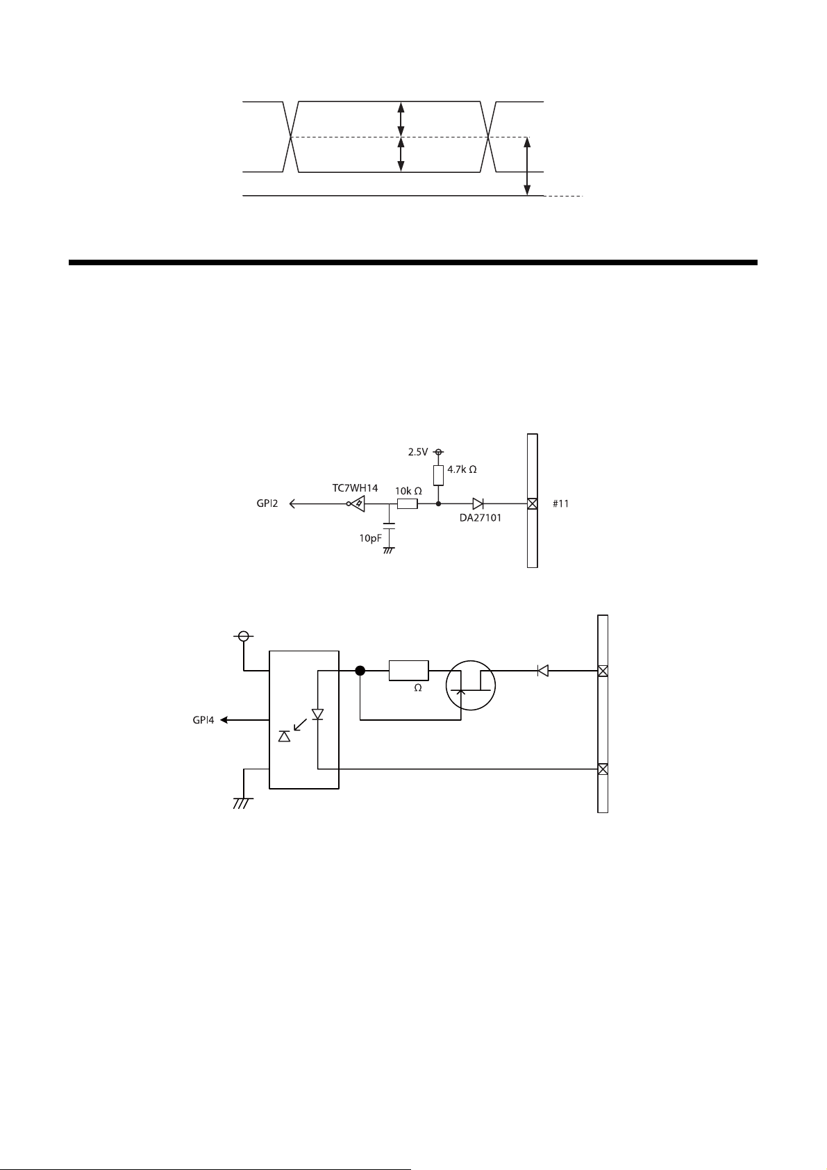
GPIO Connector
The DC IN connector’s 10th and 11th pins are for the GPI connector, the 6th and 9th pins are for the GPO (+) connector,
the 4th and 7th pins are for the GPIO switching connector. The trigger reset connector is the DC IN connector 11th pin.
If you are connecting an external device to each connector, refer to the circuit specifications below.
GPI circuit specifications
DC IN connector
3.3V
HCPL-M611
180
DC IN connector
MMBF4393LT1G
㩺㪈㪇
DA2710100L
㩺㪏
16
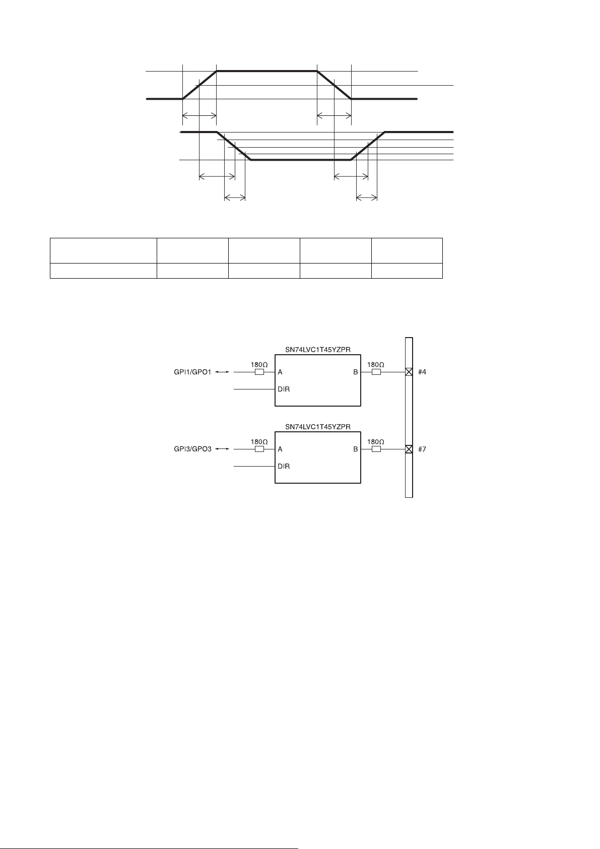
GPI (10th pin ISO)
5 V
0 V
50%
*
*
3.3 V
0 V
TDF
FT
* Rising the input signal as soon as possible.
Example
Input voltage
[V]
5.0 167 297 192 358
TDF
[ns]
GPIO circuit specifications
GPIO-MODE1
FT
[ns]
TDR
[ns]
TDR
RT
RT
[ns]
DC IN connector
90%
50%
10%
GPIO-MODE3
17
 Loading...