

Sony XCL-S600, XCL-S900, XCL-S600C, XCL-S900C Technical Manual
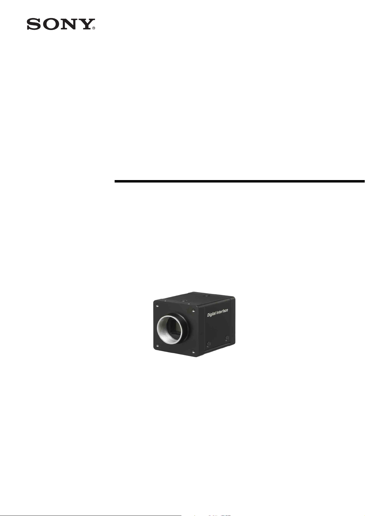
Digital Video
Camera Module
A-EHZ-100-11 (1)
Technical Manual
XCL-S600/S600C/S900/S900C
© 2013 Sony Corporation

Table of Contents
Overview
Features .................................................................. 3
Typical CCD Phenomena ...................................... 4
System Components .............................................. 5
Connection ............................................................. 5
Location and Function of Parts and
Operation ............................................................... 6
Front/Top/Bottom ............................................... 6
Using a tripod ..................................................... 6
Rear .................................................................... 7
Connecting the cables ........................................ 8
Connections
Communication Setting ........................................ 9
Camera Link Tap .................................................. 9
Data Order ........................................................... 10
1tap ................................................................... 10
2tap (when sensor tap is 1 or 2) ....................... 10
2tap (when sensor tap is 4) ............................... 11
Port assignment ................................................ 12
Color pixel array .............................................. 12
Trigger Signal Input ............................................ 13
Trigger signal polarity ...................................... 13
GPIO Connector .................................................. 14
Functions
Partial Scan .......................................................... 16
Binning ................................................................. 16
Sensor Tap ............................................................ 16
Switching sensor tap ........................................ 16
Level correction between sensor taps ............... 17
Adjusting level correction between sensor
taps ................................................................. 17
Output Bit Depth ................................................. 17
Gain ...................................................................... 17
Analog gain ...................................................... 17
Digital gain ....................................................... 17
Auto gain (AGC) .............................................. 17
Shutter (Exposure) .............................................. 18
Configuring the setting ..................................... 18
Auto exposure (AE) ......................................... 18
Combination of Continuous AGC and Continuous
AE ......................................................................... 18
Trigger Control .................................................... 19
Free run/Trigger mode ..................................... 19
Special trigger .................................................. 20
Trigger source .................................................. 21
Trigger inhibition ............................................. 21
Trigger shift ...................................................... 22
Trigger delay .................................................... 23
Trigger counter ................................................. 23
Frame counter .................................................. 23
Trigger range limit ............................................23
Trigger control ..................................................24
Frame Rate ...........................................................24
Auto frame rate .................................................24
Specifying frame rate ........................................25
Displaying frame rate .......................................25
Fastest frame rate for partial scanning ..............26
Timing Chart ........................................................28
Horizontal timing ..............................................28
Vertical timing ..................................................28
Trigger latency ..................................................29
Sensor Readout (Sensor Output) ........................30
White Balance ......................................................31
LUT .......................................................................31
Binarization ......................................................31
5-point interpolation .........................................31
Arbitrary setting ................................................32
Save LUT ..........................................................32
Color Matrix Conversion ....................................32
3 × 3 filter ..............................................................32
3 × 3 filter .........................................................32
Test Chart Output ................................................32
GPIO .....................................................................33
GPI ....................................................................33
GPO ..................................................................33
Pulse Train Generator .........................................35
Status LED ............................................................35
Temperature Readout Function .........................35
Defect Correction .................................................35
Shading Correction ..............................................36
Sensitivity Control ...............................................38
User Set .................................................................38
User set name ....................................................38
User set memory ...............................................38
Free Memory ........................................................38
User ID ..................................................................38
Saving and Startup ..............................................39
Initializing .............................................................39
Camera Information ............................................39
Help Command ....................................................39
Echo off .................................................................39
Restart ...................................................................39
Camera Control Commands
Command Form ...................................................40
Command Input and Response ..........................40
Command List ......................................................41
Parameter List ......................................................48
Specifications
Specifications ........................................................49
Spectral Sensitivity Characteristics (Typical
Values) ...................................................................52
Dimensions ............................................................53
2
Table of Contents
Overview
• Defect correction
• Shading correction
This unit is a digital video camera module that outputs
digital images utilizing LVDS via the DIGITAL IF
connector.
Features
DIGITAL IF connector
Equipped with a Camera Link standard mini connector.
The unit can output a detailed and high speed digital
image.
High definition and high speed image
capture
The unit includes a 9,000,000-pixel or 6,000,000-pixel
high-resolution CCD, with high speed read out
depending on each model.
You can select 1ch, 2ch or 4ch sensor output. The frame
rate depends on the channel selected.
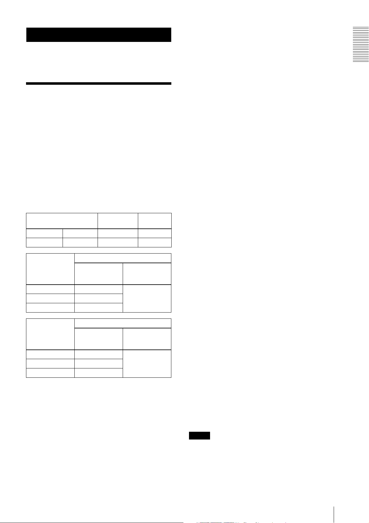
CCD size and resolution
1/1 type CCD 9 Mega XCL-S900 XCL-S900C
1/1 type CCD 6 Mega XCL-S600 XCL-S600C
Sensor tap
4ch 27 fps
1ch 7.5 fps
Sensor tap
4ch 18 fps
1ch 5 fps
Monochrome
XCL-S600/S600C
Frame rate
XCL-S900/S900C
Frame rate
model
output of pixels
output of pixels
The XCL-S900 and XCL-S600 monochrome models
use an EXview HAD CCD II
TM high sensitivity sensor,
usable even in the near-infrared region.
Various settings
Sending a command from the host device allows various
settings, including the following.
•Gain
•Shutter
• Partial scan
• Trigger control
• LUT (Look Up Table)
• Output: 8/10/12-bit or RGB 24-bit
Color
model
Maximum
(H) × (V)
2,758 × 2,2082ch 13 fps
Maximum
(H) × (V)
3,388 × 2,7122ch 9 fps
Electronic shutter function
Set anywhere from 1/100,000 sec to 2 sec in 1 µs
increments.
External trigger shutter function
By synchronizing with an external trigger signal, any
shutter timing can be used.
Partial scan
The camera module can limit the number of video
output lines to achieve high frame rates, enabling highspeed image processing.
Body fixing
The screw holes to install the camera module are located
under the front panel (the CCD reference plane).
Installing the camera module on the front panel
minimizes deviation of the optical axis.
LUT (Look Up Table)
You can switch to OFF or ON. When set to OFF, you can
select from five preset values, such as inversion,
binarization, any of five-point approximation, etc.
Switching an Output Bit Length
You can select 8-bit output, 10-bit output, or 12-bit
output.
For color models, you can also select an RGB 24-bit
output.
Binning (Monochrome camera only)
Sensitivity can be doubled by combining two pixels
aligned vertically, you can achieve a standard output
frame rate between 1.8x and 2x. Sensitivity can be
doubled by combining two pixels align horizontally.
You can set horizontal and vertical binning at the same
time.
Defect correction
The unit includes a function to reduce sensor defects,
and can be set to ON or OFF.
Shading correction
The unit includes a function to correct shading, resulting
from a light source or a particular lens, and can be set to
ON or OFF.
Note
The CCD is driven at high speed during a Partial scan or
Binning operation. In this situation, if intense light is
input to the camera, the peripheral areas of the video
image may be affected. In such a situation, adjust the
amount of light using the iris.
Overview
Features
3

Overview
Typical CCD Phenomena
The following effects on the monitor screen are
characteristic of CCD cameras. They do not indicate any
fault with the camera module.
Smear
This occurs when shooting a very bright object such as
electric lighting, the sun, or a strong reflection.
This phenomenon is caused by an electric charge
induced by infrared radiation deep in the photosensor. It
appears as a vertical smear, since the CCD imaging
element uses an interline transfer system.
Vertical aliasing
When you shoot vertical stripes or lines, they may
appear jagged.
Blemishes
A CCD image sensor consists of an array of individual
sensor elements (pixels). A malfunctioning sensor
element will cause a single pixel blemish in the picture
(This is generally not a problem.).
White speckles
While CCD image pickup device is made by an accurate
technique, imperceptible speckless may rarely come up
on the screen due to cosmic rays and so on. This is
connected to the principle of CCD image pickup device,
not a malfunction. And the white speckless are easy to
come up in the following conditions.
• Using the camera in high temperature
• When turning up the gain
Note
If strong light enters a wide area of the screen, the screen
may become dark. This is not a malfunction.
If this occurs, avoid strong light or adjust the lens iris to
reduce the light amount.
Note on laser beams
Laser beams may damage a CCD. You are cautioned
that the surface of a CCD should not be exposed to
laser beam radiation in an environment where a laser
beam device is used.
4
Typical CCD Phenomena
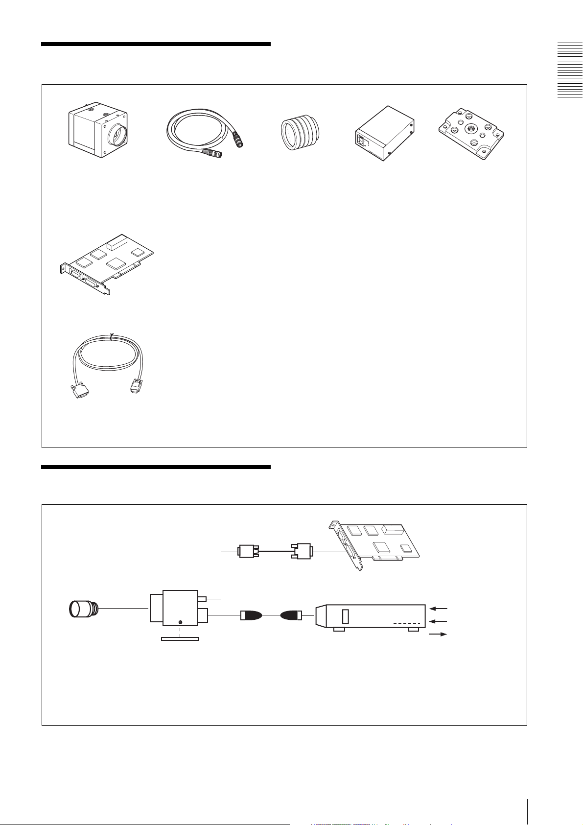
System Components
Overview
Video Camera Module Camera cable
Camera module interface
board
Camera Link cable
(Sony Camera-compatible)
CCXC-12P02N (2 m, 6.6 ft)
CCXC-12P05N (5 m, 16.4 ft)
CCXC-12P10N (10 m, 32.8 ft)
CCXC-12P25N (25 m, 82 ft)
Install the board in a PCI bus slot in devices such as a computer. Select a commercially
available interface board compatible with the Camera Link feature. You can use either a board
that supports PoCL, or one that does not.
Due to the performance of the board, the frame rate may become low according to lack of
processing capacity. To have this product output frames at the highest speed, use a board
corresponding to PCI-Express.
Performance may also be dependent on the host device (e.g., Computer), so consult the
dealer if images are not displayed properly.
This cable connects to the DIGITAL IF connector on the rear panel of the camera module.
Image/control signals are transmitted via this cable.
Select a proper cable as the maximum usable length of a cable differs due to the attribute of
each cable.
Spotted noise may appear in a specific brightness in the window according to the attribute of
the cable. If this noise is an obstacle, shorten the cable.
C-mount lens
Use a lens appropriate
for the pixel count of
the camera.
Camera adaptor
DC-700/700CE
Tripod adaptor
VCT-ST70I (Insulated
type)
Connection
Camera Link cable
Camera module
C-mount lens
Camera cable
CCXC-12P02N
Tripod adaptor
VCT-ST70I
Power supply
You can supply power via the DC IN connector using the power adapter.
Use DC-700/700CE which is the stable power source free from ripple or noise.
CCXC-12P05N
CCXC-12P10N
CCXC-12P25N
Camera module interface board
Camera adaptor
DC-700/700CE
AC
TRIG
Internal signal
output
System Components
5
Location and Function of Parts and Operation
Overview
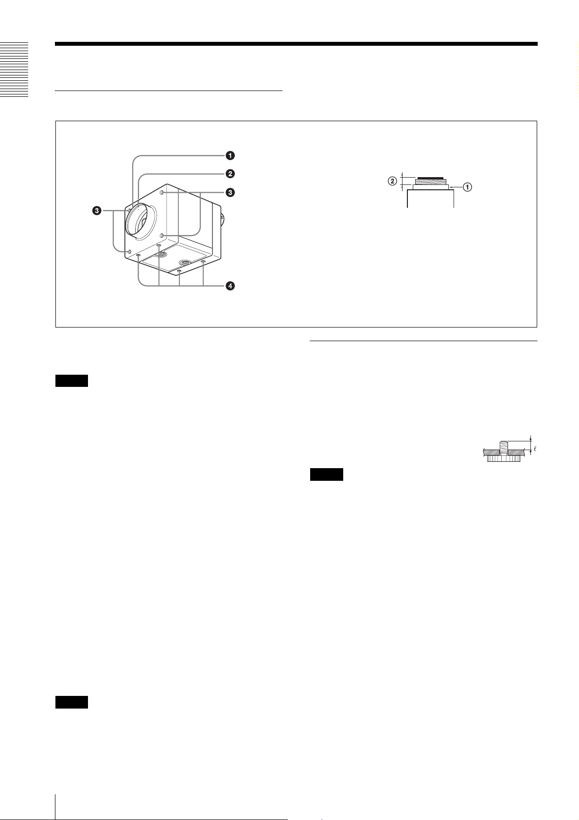
Front/Top/Bottom
Lens mount (C-mount)
Guide screw holes (Top)
LED light screw holes
Guide screw holes / Tripod screw holes (Bottom)
a Lens mount (C-mount)
Attach any C-mount lens or other optical equipment.
Note
The lens must not project more than 10 mm (13/32 inch)
from the lens mount.
A Lens mount face B 10 mm (13/32 inch) or less
When you use the camera with the lens attached, the
resolution of the image output from the camera may
differ according to the performance of the lens. Note it
when you select a lens.
The performance of a lens may change according to the
aperture level.
If the resolution is not enough, adjust the aperture level.
Using a tripod
To use the tripod, install the tripod adaptor VCT-ST70I
(not supplied) on the camera module.
Use a tripod screw with a protrusion (4) extending from
the installation surface, as follows, and tighten it, using
a screwdriver. Be sure that the protrusion (4) does not
exceed 5.5 mm (0.22 in.) in length.
Length 4.5 to 5.5 mm
Length 0.18 to 0.22 inches
Note
If you install a tripod adapter (not supplied), use the
screws (M3 × 8 (4)) provided.
b Guide screw holes (Top)
c LED light screw holes
Use these screw holes to attach the LED light to the
camera module.
Use an adapter appropriate for the LED light as required.
d Guide screw holes / Tripod screw holes (Bottom)
These precision screw holes are for locking the camera
module. Locking the camera module into these holes
secures the optical axis alignment.
When using a tripod, use these four screw holes to attach
a VCT-ST70I tripod adaptor.
Note
Refer to Demensions in page 53 for about the position/
size of the Guide hole and the Reference hole.
6
Location and Function of Parts and Operation

Rear
e DC IN (DC power input) connector (12-pin)
g Status LED
f DIGITAL IF (Interface) connector (26-pin mini connector)
Overview
e DC IN (DC power input) connector (12-pin)
You can connect a camera cable CCXC-12P05N etc. to
input the +12 V DC power supply.
For details on the pin arrangement, see the following
table.
Pin No. Signal Pin No. Signal
1Ground 7GPI3/GPO3
2 DC +12 V 8 GPI4(ISO-)
3 ISO Ground 9 GPO4(ISO)
4 GPI1/GPO1 10 GPI4(ISO+)
5 GPO2(ISO-) 11 GPI2
6 GPO2(ISO+) 12 ISO Ground
Power input
Pin 1 (Ground) and pin 2 (DC +12 V) are used.
Signal input
Pins 4, 7, 10 and 11 (GPI1/3/4/2) are used for GPI input
or trigger input.
When selecting 1 system for GPI (ISO):
– GPI4 (ISO+) (pin 10) and GPI4 (ISO-) (pin 8) are
used.
When selecting 2 systems for GPI:
– GPI1 (pin 4*) and Ground (pin 1) are used.
– GPI3 (pin 7*) and Ground (pin 1) are used.
* Pins 4 and 7 can switch GPI input and GPO output, by
external command. The initial value is GPI.
Signal output
Pins 4, 6, 7 and 9 (GPO1/2/3/4) allow you to select GPO
from the exposure signal, strobe control signal, Hi/Low
fixed value, etc.
When selecting 2 systems for GPO (ISO):
– GPO4 (ISO) (pin 9) and ISO Ground (pins 3 and 12)
are used.
– GPO2 (ISO+) (pin 6) and GPO2 (ISO-) (pin 5) are
used.
When selecting 2 systems for GPO:
– GPO1 (pin 4*) and Ground (pin 1) are used.
– GPO3 (pin 7*) and Ground (pin 1) are used.
* The initial value of pins 4 and 7 is GPI. Switch to GPO
output by external command.
f DIGITAL IF (Interface) connector (26-pin)
You can connect a Camera Link cable to this connector
to control a camera module from a host device utilizing
the serial communication protocol while outputting a
video signal from the camera module. You can input the
external trigger signal via the DIGITAL IF connector
and operate a camera module in the external trigger
mode.
The following table shows the relation between the pin
numbers of the DIGITAL IF connector and the input/
output signals and the like.
Pin No. Signal Pin No. Signal
1 Ground 14 Ground
2X0– 15X0+
3X1– 16X1+
4X2– 17X2+
5 XCLK– 18 XCLK+
6X3– 19X3+
7 SerTC+ 20 SerTC–
8SerTFG– 21SerTFG+
9 CC1– 22 CC1+
10 CC2+ 23 CC2–
11 CC3– 24 CC3+
12 CC4+ 25 CC4–
13 Ground 26 Ground
Location and Function of Parts and Operation
7
Overview
g Status LED (Green)
When power is on, this LED lights up.
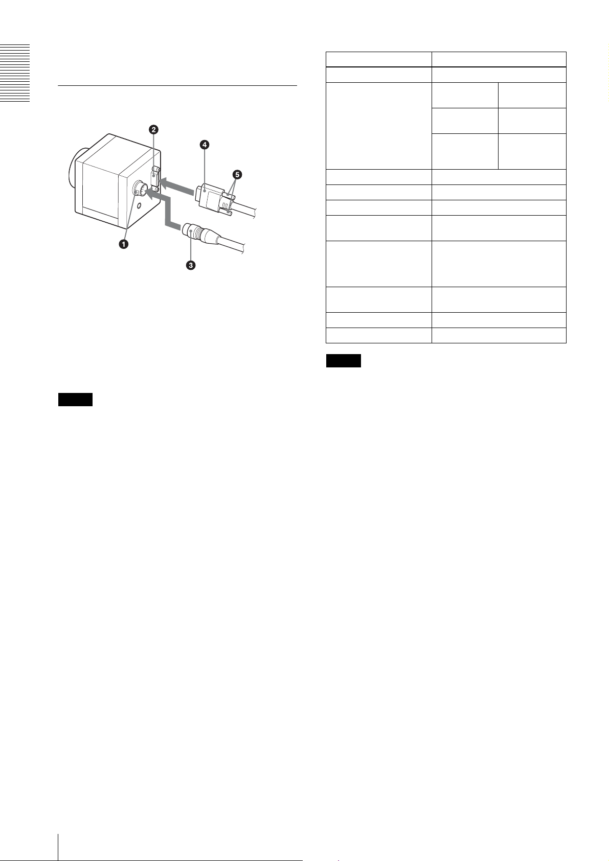
Connecting the cables
DIGITAL IF connector
Camera Link cable
Fastening
screws
DC IN
connector
Camera cable
Connect the camera cable to the DC IN connector and
the Camera Link cable to the DIGITAL IF cable
respectively. When you connect the Camera Link cable,
turn the two fastening screws on the connector to secure
the cable tightly.
Connect the other end of the camera cable to the DC700/700CE and the other end of the Camera Link cable
to the camera module interface board.
Note
This camera does not support PoCL. To prevent the
camera from malfunction, do not supply power from the
Camera Link board.
Controlling the camera from the host
device
You can control the camera from host device such as a
computer. The following table shows the major control
functions.
You can send a command corresponding to the control
items, with parameters for the desired settings, if
necessary, from the host device to control the camera.
Refer to “Camera Control Commands” on page 40 for
details on how to send a command, the commands, and
their parameters.
Control functions Description
Operating mode Free run/Trigger
Shutter speed Free run 1/100,000 sec to
Trigger edge
detection
Trigger pulse
width detection
Gain 0 dB to 18 dB
Partial Scan Variable, 4-line increments
LUT (Look Up Table) OFF/ON (Mode: 5 types)
External trigger input DIGITAL IF connector/DC IN
connector
Video output switch Monochrome model: Mono 8/10/
Binning (Monochrome
camera only)
Defect correction OFF/ON
Shading correction OFF/ON
Note
12-bit
Color model: Raw 8/10/12-bit,
RGB 24-bit
2 × 1, 1 × 2, 2 × 2
2 sec
1/100,000 sec t o
2 sec
Setting by
trigger pulse
width
Make sure to supply power to the camera module and
confirm that the camera module is operating before
inputting a trigger signal. If you input trigger signal to a
camera module without the power supplied, this may
cause a malfunction of the camera module.
Image at partial scan
Depending on the image input board of the camera you
are using, if settings for the boards received image size
and the image size output from a camera do not
conform, picture noise or sync issues may occur.
8
Location and Function of Parts and Operation
Connections
Communication Setting
The serial port assigned to the camera link board is used. The communication system is an asynchronous method
compliant with RS-232C. The following table shows the transmission control specifications. Command inputs are
echoed back. Inputs are not case-sensitive.
Baud rate 115200/57600/38400/19200/9600 [bps]
Data bit 8
Parity None
Stop bit 1
Flow control None
Default values are underlined. (same applies hereinafter)
Camera Link Tap
Connections
1tap output or 2tap output can be selected, regardless of the camera settings. Output clock frequencies are as follows.
Lowering the output clock frequency improves the tolerance to video signal attenuation, which allows the camera link
cable length to be extended. Thus, it is recommended to use with 2tap unless there are board restrictions. Only the
selection of sensor tap1 or 2, or camera link tap1 is available for RGB24-bit output. The output of sensor tap4 is only
available for the selection of camera link tap2.
Sensor Tap
Command
SENSOR-TAP
1 available
2 available
4
Camera Link Tap Command
CAMERALINK-TAP
12
available
Clock 54 MHz
Clock 84 MHz
unavailable available
Clock 27 MHz
available
Clock 42 MHz
Clock 84 MHz
Communication Setting
9
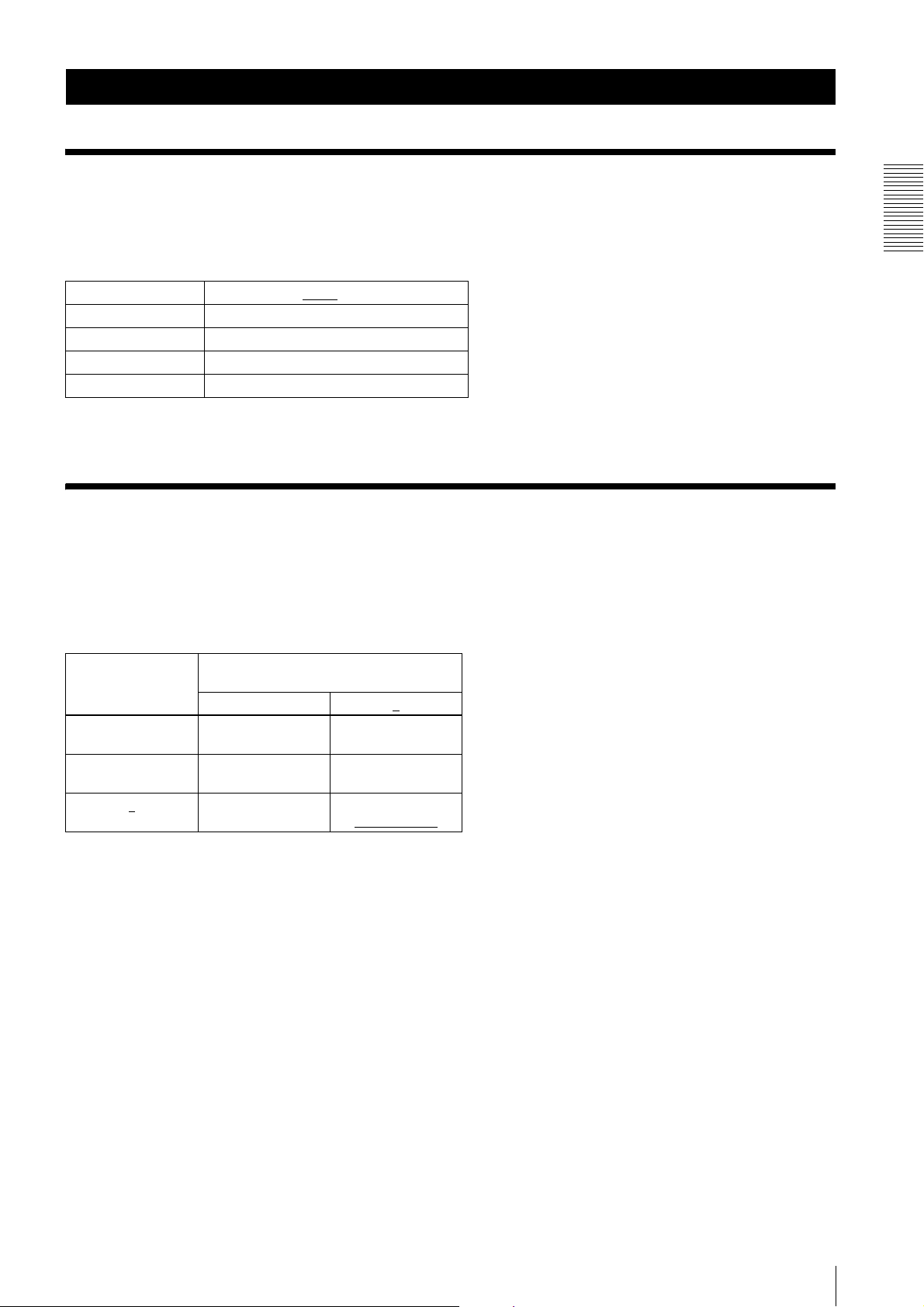
Data Order
Figures below show the data order when an image of M × N pixels is transmitted in camera link tap1 and camera link
tap2.
1tap
Connections
2tap
STROBE
Video output
STROBE
Video output
1tap
M × N pixels
2tap (when sensor tap is 1 or 2)
M × N pixels
10
Data Order

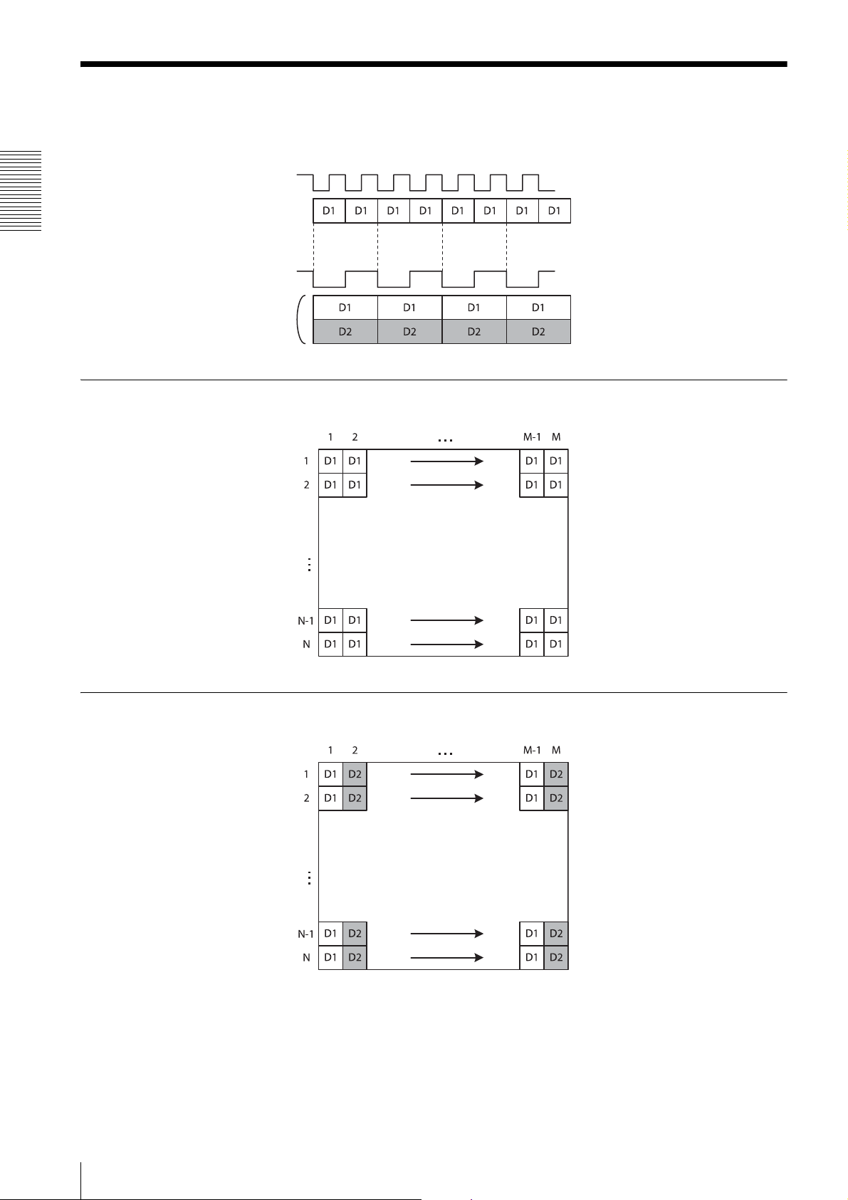
2tap (when sensor tap is 4)
M × N pixels
* The order of the lines output is as follows:
For D1 (upper half of the screen), the order is from Line 1 to Line N/2.
For D2 (lower half of the screen), the order is from Line N to Line N/2 + 1.
Connections
Data Order
11

Port assignment
The following table shows the assignment for the three ports (A, B, and C) and the respective video signals (D1, D2,
and DR, DG, DB for RGB24-bit) for 1tap/2tap as defined in the base configuration.
Port 1tap 2tap
8 bit 10 bit 12 bit RGB 24bit 8 bit 10 bit 12 bit
Port A0 D1[0] D1[0] D1[0] DR[0] D1[0] D1[0] D1[0]
Port A1 D1[1] D1[1] D1[1] DR[1] D1[1] D1[1] D1[1]
Connections
Port A2 D1[2] D1[2] D1[2] DR[2] D1[2] D1[2] D1[2]
Port A3 D1[3] D1[3] D1[3] DR[3] D1[3] D1[3] D1[3]
Port A4 D1[4] D1[4] D1[4] DR[4] D1[4] D1[4] D1[4]
Port A5 D1[5] D1[5] D1[5] DR[5] D1[5] D1[5] D1[5]
Port A6 D1[6] D1[6] D1[6] DR[6] D1[6] D1[6] D1[6]
Port A7 D1[7] D1[7] D1[7] DR[7] D1[7] D1[7] D1[7]
Port B0 D1[8] D1[8] DG[0] D2[0] D1[8] D1[8]
Port B1 D1[9] D1[9] DG[1] D2[1] D1[9] D1[9]
Port B2 D1[10] DG[2] D2[2] D1[10]
Port B3 D1[11] DG[3] D2[3] D1[11]
Port B4 DG[4] D2[4] D2[8] D2[8]
Port B5 DG[5] D2[5] D2[9] D2[9]
Port B6 DG[6] D2[6] D2[10]
Port B7 DG[7] D2[7] D2[11]
Port C0 DB[0] D2[0] D2[0]
Port C1 DB[1] D2[1] D2[1]
Port C2 DB[2] D2[2] D2[2]
Port C3 DB[3] D2[3] D2[3]
Port C4 DB[4] D2[4] D2[4]
Port C5 DB[5] D2[5] D2[5]
Port C6 DB[6] D2[6] D2[6]
Port C7 DB[7] D2[7] D2[7]
Color pixel array
In the case of 8-bit, 10-bit, and 12-bit outputs, signals of all pixels are output sequentially according to the Bayer Array
shown below.
In the case of RGB24-bit, R, G, and B are 8 bits respectively per 1 pixel.
12
Data Order
Trigger Signal Input
Trigger signals can be input via the 4th/7th/10th/11th pins of the DC IN connector, the CC1, CC2, CC3, CC4 pins of
the Digital IF connector, or the software command. Switchover of the trigger signal can be changed via the TRG-SRC
command.
command param Trigger signal assigned pin
TRG-SRC 4 DC IN connector 4th pin*
7 DC IN connector 7th pin*
10 DC IN connector 10th pin
11
101 Digital IF connector 22nd [+]/9th [-] (CC1)
102 Digital IF connector 10th [+]/23th [-] (CC2)
103 Digital IF connector 24th [+]/11th [-] (CC3)
104 Digital IF connector 12nd [+]/25th [-] (CC4)
0 Software command (TRG-SOFT)
20 OR of DC IN connector 4th/7th/10th/11th pin
* DC IN connector 4th pin and 7th pin are available only when the GPIO input/output setting is switched to input.
Trigger signal polarity
DC IN connector 11th pin
Connections
Positive refers to a trigger signal polarity activated while rising from Low to Hi, or during the Hi interval. Negative refers
to a trigger signal polarity activated while falling from Hi to Low, or during the Low interval. The default value of a
camera is Negative.
Use the 11th pin to input a trigger signal
The DC IN connector 11th pin is pulled up on the camera side. When a connector is open, the trigger signal is at the
high level and is logically inactive. Note that when Positive of DC IN connector 11th pin is selected as a trigger input,
when the terminal is open, the trigger will be activated.
Use the 4th or 7th pin to input a trigger signal
When input is via the 11th pin, the high level value varies between 2 V to 24 V and 3.5 V to 5.5 V. Low level value is
0 V to 0.4 V.
Use the 10th (ISO+) or 8th (ISO-) pin to input a trigger signal
When input is via the 11th pin, the high level value varies between 2 V to 24 V and 5 V to 24 V. Low level value is 0 V
to 0.4 V.
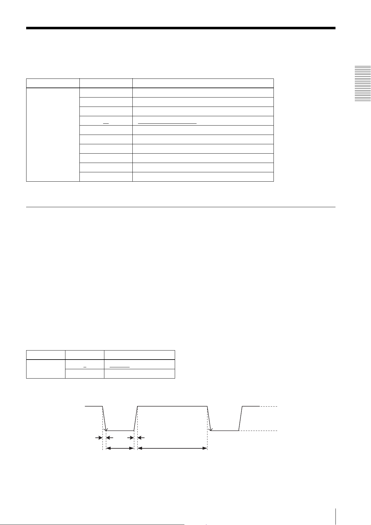
command param Trigger signal polarity
TRG-POL 0
1 Positive
Negative
DC IN connector specifications
2.0µs or less
10µs to 2s
2.0µs or less
100µs or more
Trigger input polarity = Negative
2 to 24V
0 to 0.4V
Trigger Signal Input
13
2.0µs or less
2 to 24V
0 to 0.4V
2.0µs or less
10µs to 2s
100µs or more
Trigger input polarity = Positive
Connections
Note
When inputting a trigger signal to the camera using the DC-700, use DC 5 V or less at the logical high level.
Digital IF connector specifications
0.30 to 0.40v
0.30 to 0.40v
1.125 to 1.375v
GND
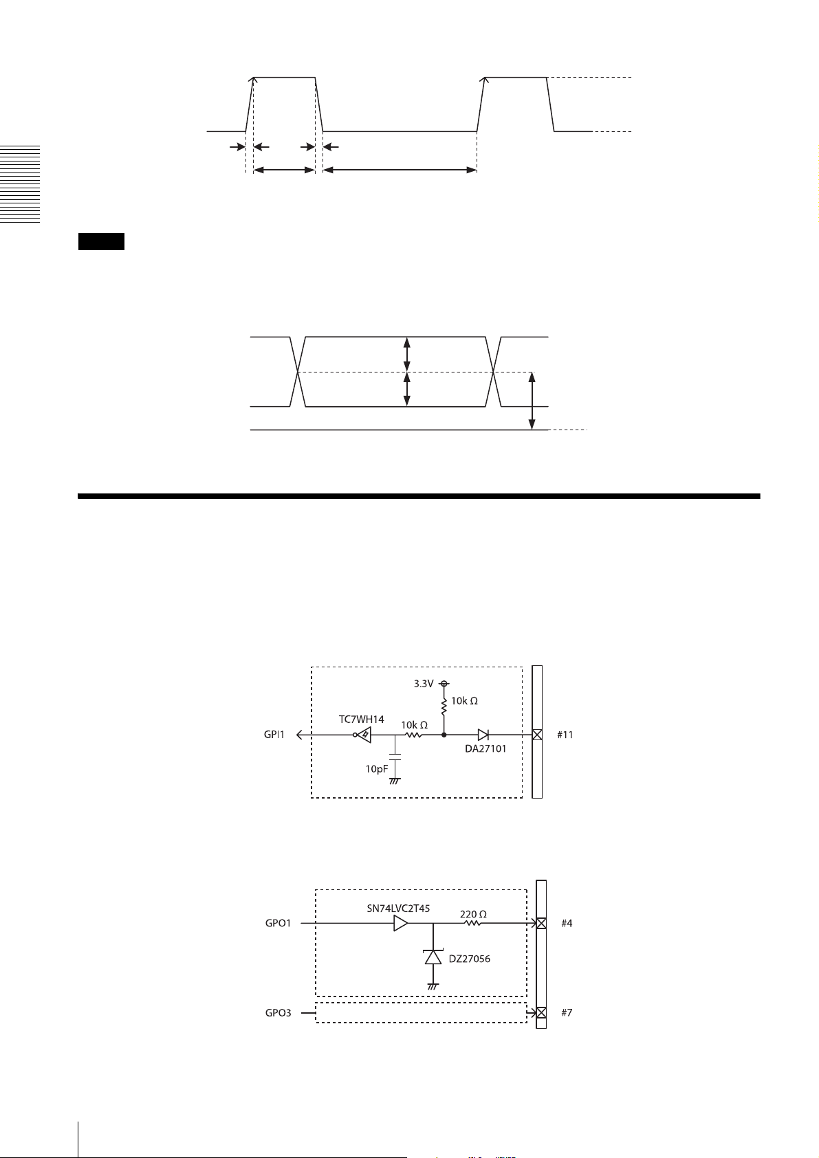
GPIO Connector
The DC IN connector’s 10th and 11th pins are for the GPI connector, the 6th and 9th pins are for the GPO (+) connector,
the 4th and 7th pins are for the GPIO switching connector. The trigger reset connector is the DC IN connector 11th pin.
If you are connecting an external device to each connector, refer to the circuit specifications below.
GPI circuit specifications
GPO circuit specifications
DC IN connector
DC IN connector
As GPO1
14
GPIO Connector
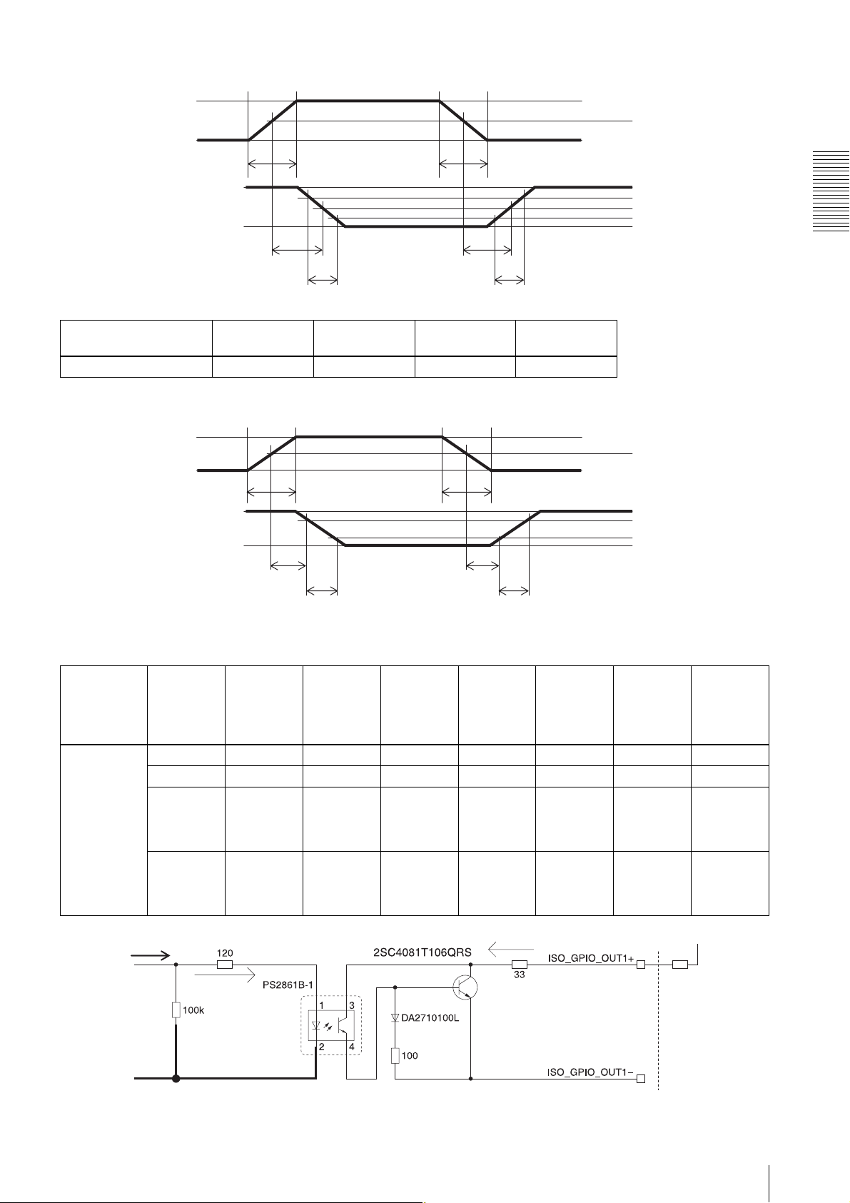
GPIO input (10th pin ISO)
5V
0V
50%
*
*
3.3V
0V
TDF
FT
Example
Input voltage
[V]
5.0 167 297 192 358
TDF
[ns]
FT
[ns]
GPIO output (6th pin ISO or 9th pin ISO)
3.3V
0V
**
3.3V
0.9V
TDF
FT
TDR
[ns]
TDR
TDR
RT
RT
RT
[ns]
90%
50%
10%
50%
90%
10%
Connections
* Rising the input signal as soon as possible.
Example
When connecting to an external power supply, be sure to use a pull-up resistor for a current limit of less than 50 mA.
Normal
temperature
Input from control IC
Supply
voltage
of the
output
[V]
3.3 470 Ω 5.07 0.75 0.49 24 35 0.916
5.0 820 Ω 4.98 0.73 0.63 28 46 0.909
12.0 Two
24.0 Eight
Pull-up
resistor
Use 1/16
W
2200 Ω
resistors
in parallel
8200 Ω
resistors
in parallel
Current
[mA]
TDF
[µs]
FT
[µs]
TDR
[µs]
RT
[µs]
Output
voltage
9.87 0.71 1.05 36 64 1.112
21.85 0.73 1.45 45 76 1.571
External power supply
Pull-up resistor
[V]
GPIO Connector
15
Functions
Functions
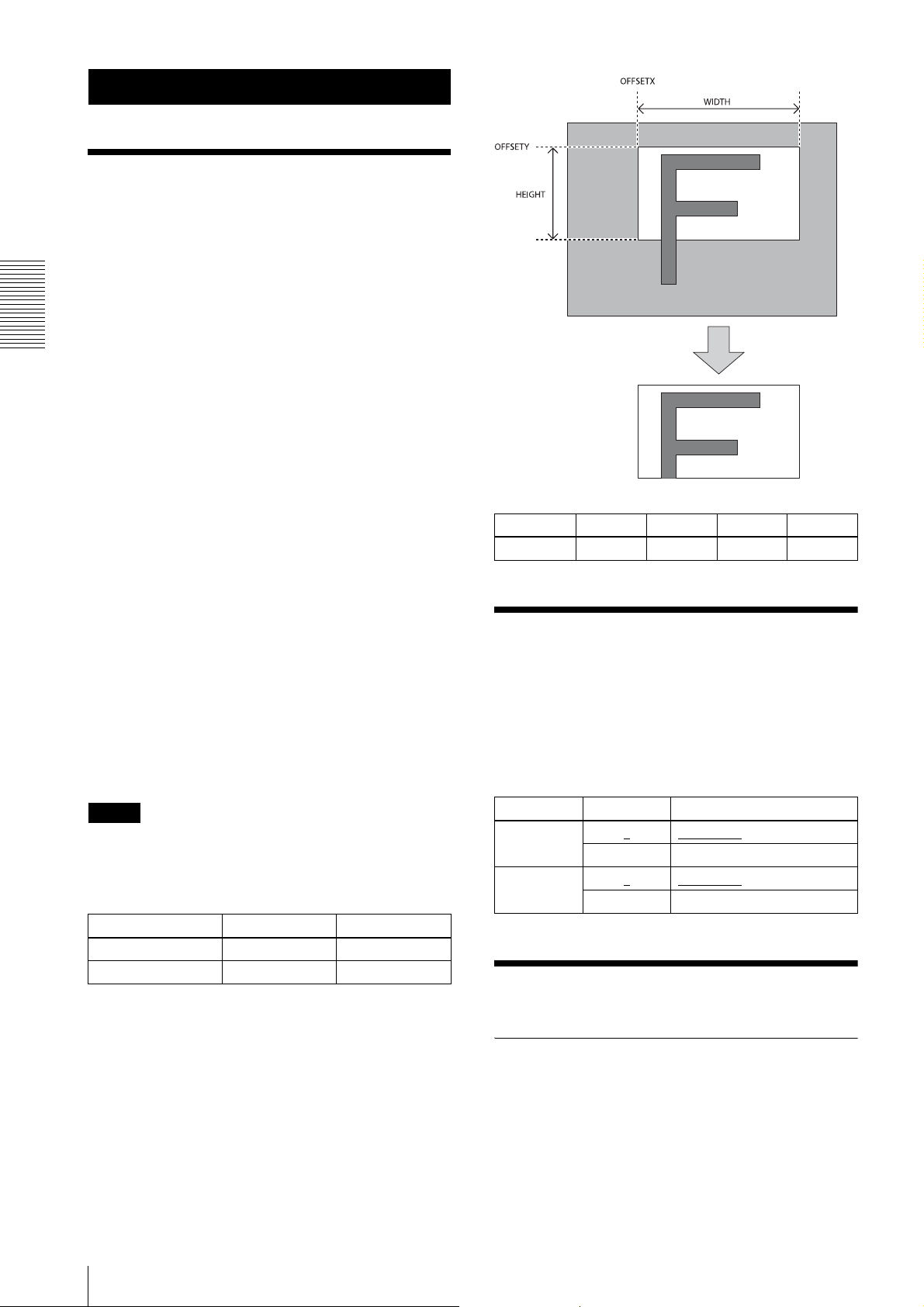
Partial Scan
Only the area selected from the effective pixel area can
be read out. Clearing unnecessary parts at high-speed
allows high-speed reading. The area size is selected by
the HEIGHT and WIDTH commands, and the read
beginning point is selected by the OFFSETX and
OFFSETY commands. Using the ROI command, you
can set HEIGHT, WIDTH, OFFSETX and OFFSETY at
the same time. Reducing HEIGHT increases the frame
rate, but changing WIDTH does not change the frame
rate. Partial scan can be set with or without a trigger.
Binning can be used at the same time.
OFFSETX and OFFSETY relate to WIDTH and
HEIGHT as follows:
OFFSETX + WIDTH ≤ WIDTH (maximum value)
OFFSETY + HEIGHT ≤ HEIGHT (maximum value)
When selecting sensor tap4, a central line divides the
screen into two halves symmetrically for a vertical
division. For the relationship between OFFSETY and
HEIGHT, see the following formula:
OFFSETY × 2 + HEIGHT = Maximum lines
(For XCL-S600 the maximum number of lines is 2208,
for XCL-S900 the maximum number of lines is 2712)
Because the value of OFFSET is set automatically by
HEIGHT and the maximum number of lines, the
command to change OFFSETY is not available.
(Example of XCL-S900)
>SENSOR-TAP 4
>HEIGHT 480 t HEIGHT is 480, OFFSETY is set to
1116 ( = (2712 – 480) ÷ 2)
>OFFSETY 0 t OFFSETY change not available.
Partial scan
command param1 param2 param3 param4
ROI Width Height OffsetX OffsetY
Binning
By adding 2 vertical pixels or 2 horizontal pixels, the
frame rate in vertical binning is increased along with the
sensitivity. The color camera cannot set this. This can be
set with or without a trigger. Partial scan can be used
concurrently and horizontal and vertical can be set at the
same time.
Note
Since the shutter setting has priority, use a shutter speed
high enough to enable partial scan at a higher frame rate.
Configurable range
WIDTH HEIGHT
XCL-S600/S600C 16 ~ 2758 4 ~ 2208
XCL-S900/S900C 16 ~ 3388 4 ~ 2712
Configurable values
OFFSETX, WIDTH: 2-step increments
OFFSETY, HEIGHT: 4-step increments
command param Setting
VBIN 1
2 Vertical binning
HBIN 1
2 Horizontal binning
No binning
No binning
Sensor Tap
Switching sensor tap
This unit has a CCD with 4-channel output which is
available for 4-channel, 2-channel and 1-channel
reading. The reading speed becomes faster as the value
of the channel number increases.
16
Partial Scan
command param Setting
SENSOR TAP 1 1-channel
2 2-channel
4
4-channel
command param Setting
to
BL-ABLIMIT
1 to 512
16383
Setting lower value prevents
excessive detection
Level correction between sensor taps
Since XCL-S600/S600C and XCL- S900/S900C have a
CCD with 4-channel signal outputs, output level
differences may occur during channel reading due to the
characteristic difference between channels. Level
correction between sensor taps can correct the level
differences. A command for one-push (automatically
detecting the level difference and adjusting only once),
continuous (constantly detecting the level difference and
adjusting continuously), and manual correction
(correcting left and right manually) is provided. After
one-push is performed once, the state returns to manual
designation.
command param Setting
BLACKLEV
EL-AUTOBALANCE
(BL-AB)
0
1 One-push (only once)
2 Continuous (consecutive)
Manual designation is performed by the BL-ADJ-1/2
command. The left screen is for TAP1 and the right
screen is for TAP2. One push and continuous commands
automatically set the value for TAP2.
command param Setting
BL-ADJ-1 -255 to 0
BL-ADJ-2 -255 to 0
to 255 Black level correction
to 255 Black level correction
Manual designation
value for left screen
value for right screen
Output Bit Depth
Monochrome cameras can switch between 8 bits, 10
bits, and 12 bits. Color cameras can switch between Raw
output 8 bits, 10 bits, 12 bits, and RGB output 24 bits.
command param Setting
PIXEL-DEPTH 8
/10/12/24 24 is only for color camera
Gain
Analog gain
The analog gain can be set finely in 1 dB unit or bit level
(up to 18 dB). It can be set per the sensor tap as well.
command param Setting
GAIN 0
GAIN-TAP1 0
GAIN-TAP2 0
GAIN-FINE 0
GAINFINE-TAP1
GAINFINE-TAP2
to 18 Gain dB unit (full screen)
to 18 Gain dB unit (left screen)
to 18 Gain dB unit (right screen)
to 512 Gain advanced setting (full
screen)
to 512 Gain advanced setting (left
0
to 512 Gain advanced setting (right
0
screen)
screen)
Functions
Adjusting level correction between sensor taps
The one-push command should be executed after setting
the output level to all black by removing light sources.
When One-push or Continuous is performed as taking
an image normally, the shade difference of an object is
detected as the level difference between taps and level
correction may not work properly on rare occasions. In
this case, the limit value (BL-AB-LIMIT) should be
adjusted so that the level is automatically adjusted to the
proper value. Lowering the value allows preventing
excessive detection but interferes the normal level
correction between taps to work properly. The level
should be adjusted accordingly since the optimal value
differs depending on the environment (such as an object
and light source) and camera settings (such as gain and
shutter).
Digital gain
The digital gain is not implemented in this device.
Auto gain (AGC)
By executing the GAIN-AUTO command, the gain is
automatically adjusted according to the image pickup
environment. AGC works so that the average level in a
detection frame may reach AGC-LEVEL. The AGC
detection frame is set to the central region by default.
The detection frame can be displayed or the detection
area changed.
Output Bit Depth
17
 Loading...