

Page 1

Technical Manual
A-CNA-100-12 (1)
Black and White
Digital Video
Camera Module
© 2007 Sony Corporation
XCL-5000
Page 2

Table of Contents
2
Table of Contents
Overview
Features .................................................................. 3
Typical CCD Phenomena ...................................... 4
System Components .............................................. 5
Connection ............................................................. 5
Location and Function of Parts and Operation .. 6
Front/Top/Bottom ............................................... 6
Rear .................................................................... 7
Connecting the cables ........................................ 8
Trigger signal specifications .............................. 8
DVAL/Exposure output specific (only DC IN
terminal) ........................................................... 8
Functions
CCD loaded on XCL-5000 .................................... 9
Camera mode ....................................................... 10
Normal mode .................................................... 10
Binning mode ................................................... 11
Partial scan mode ............................................. 12
Trigger mode .................................................... 16
Trigger binning mode ....................................... 17
Trigger partial scan mode ................................. 18
Shutter Setting ..................................................... 20
DSP Operation ..................................................... 21
Signal process block chart ................................ 21
Right/Left digital clamp ................................... 22
Digital gain ....................................................... 22
Gamma correction ............................................ 23
Filter ................................................................. 25
Edge detection/Emphasizing process ............... 26
Binarization ...................................................... 27
Digital pedestal ................................................ 28
Switching image output: 8/10/12 bit width
selection ........................................................ 28
Grayscale chart ................................................. 28
Camera Control Commands
General ................................................................. 29
Serial Communication Specifications .............. 29
Command system ............................................. 29
Command format ............................................. 29
Command input and response .......................... 29
Command Specification ...................................... 30
Camera control commands ............................... 30
AFE Setting Command .................................... 30
DTL/Binarization Setting Command ............... 31
Digital Setting Command ................................. 31
Gamma Setting Command ............................... 32
Filter Setting Command ................................... 32
Binning / Partial Setting Command ................. 32
IN/OUT Setting Command .............................. 32
Setting Value Control Command ..................... 33
Setting Initialization Command ........................33
Save Setting Command .....................................33
Read Setting Command ....................................33
Setting Value Accession Command ..................34
Others ................................................................35
Command Limitation ........................................35
Command List ......................................................36
Parameter List ......................................................37
Specifications
Specifications ........................................................38
Spectral Sensitivity Characteristics (Typical
Values) ...................................................................39
XCL-5000 Dimensions .........................................40
Page 3

Overview
Features
3
Overview
The XCL-5000 is a monochrome digital video camera
module. This camera module outputs digital images
utilizing LVDS via the digital interface connector.
Features
Digital interface connector
Equipped with a Camera Link standard small connector.
The XCL-5000 can output a digital image at 15 frames
per second.
High image quality
The XCL-5000 has a progressive scan CCD of
5,000,000 pixels. Both cameras produce high-resolution
images. By adopting square pixels, images can be
processed using the original aspect ratio without a
converting procedure.
Various mode settings
Sending a command from the host device allows the
following mode settings.
•Gain
• Read mode: normal /binning
• Partial scan
• Shutter: Normal/Trigger shutter
• Shutter speed
• Gamma
• Edge detection, Edge emphasis
• Binarization
• Switching an Output Bit Length
Electronic shutter function
Shutter speed can be selected from variety of available
speeds.
External trigger shutter function (2 to
1/10000 sec.)
You can obtain a freeze picture by inputting an external
trigger. This function is useful to shoot a fast-moving
object clearly.
Partial scan
The camera module can limit the number of effective
video output lines to achieve high frame rates, enabling
high-speed image processing.
Binning
By “binning” two pixels that align vertically, you can
acquire a frame rate twice as high as that in the normal
mode.
Body fixing
The screw holes to install the camera module are located
under the front panel (the CCD reference plane).
Installing the camera module on the front panel
minimizes deviation of the optical axis.
Gamma
You can select Off, Manual or Default. When you select
Manual, you can draw up an original gamma line.
Edge detection, Edge emphasis
Edge detection detects an Edge from a picture, and
outputs an image made of the Edge only.
Edge emphasis outputs a clear image emphasized on the
Edge.
Binarization
Outputs an binarized image. Threshold can be changed.
Switching an Output Bit Length
You can select 12 bit output, 10 bit output, or 8 bit
output.
Note
The CCD is driven at high speed during a Partial scan or
Binning operation. In this situation, if intense light is
input to the camera, the peripheral areas of the video
image may be affected. In such a situation, adjust the
amout of light using the iris.
Page 4

Overview
Typical CCD Phenomena
4
Typical CCD Phenomena
The following effects on the monitor screen are
characteristic of CCD cameras. They do not indicate any
fault with the camera module.
Smear
This occurs when shooting a very bright object such as
electric lighting, the sun, or a strong reflection.
This phenomenon is caused by an electric charge
induced by infrared radiation deep in the photosensor. It
appears as a vertical smear, since the CCD imaging
element uses an interline transfer system.
Vertical aliasing
When you shoot vertical stripes or lines, they may
appear jagged.
Blemishes
A CCD image sensor consists of an array of individual
sensor elements (pixels). A malfunctioning sensor
element will cause a single pixel blemish in the picture.
(This is generally not a problem.)
White speckles
While CCD image pickup device is made by an accurate
technique, imperceptible speckless may rarely come up
on the screen due to cosmic rays and so on. This is
connected to the principle of CCD image pickup device,
not a malfunction. And the white speckless are easy to
come up in the following conditions.
• Using the camera in high temperature
• When turning up the gain
Step between left and right
As CCD used in this camera adopts the left-right 2ch
output system, left half and right half of the window are
output individually. Sometimes a step or line may appear
in the center of the window according to the setting
mode of the camera. This is not a malfunction.
Note
If strong light enters a wide area of the screen, the screen
may become dark. This is not a malfunction. If this
occurs, avoid strong light or adjust the lens iris to reduce
the light amount.
Page 5
Overview
System Components
5
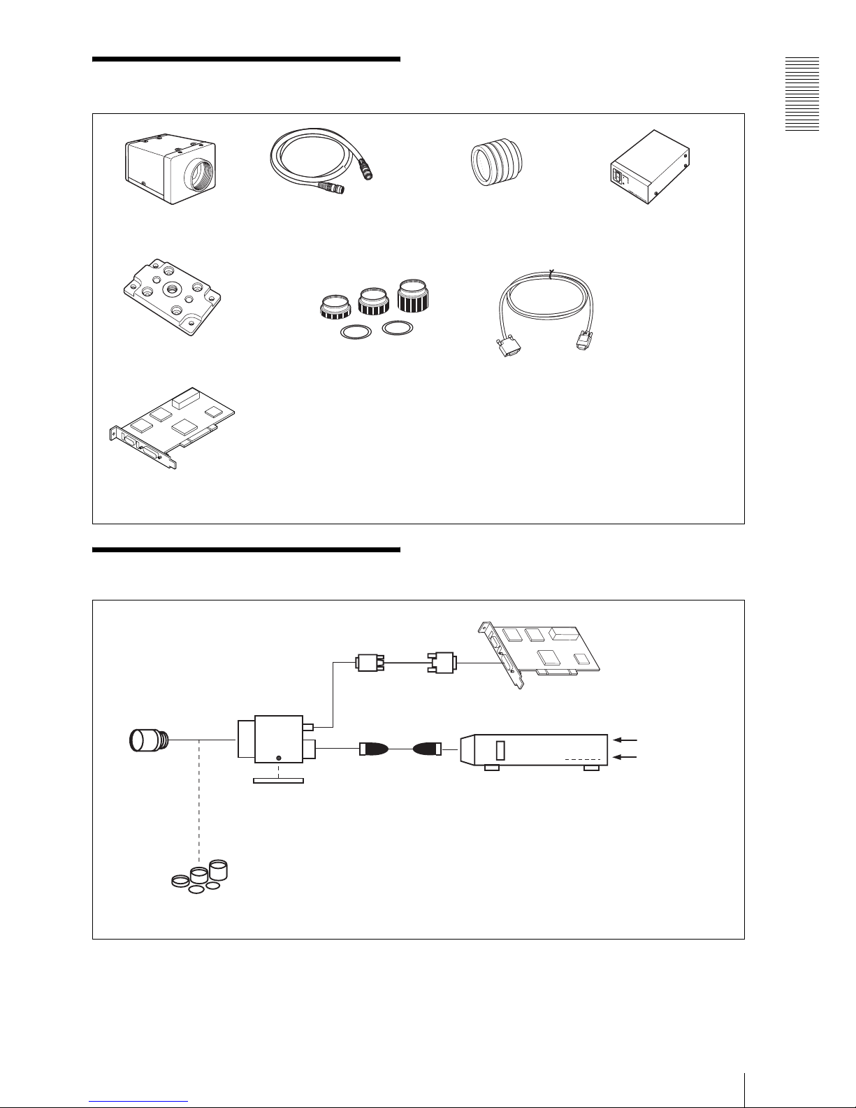
System Components
Connection
Video Camera Module
XCL-5000
Camera cable
CCXC-12P02N (2 m, 6.6 ft)
CCXC-12P05N (5 m, 16.4 ft)
CCXC-12P10N (10 m, 32.8 ft)
CCXC-12P25N (25 m, 82 ft)
C-mount lens
High-resolution lens
Camera adaptor
DC-700/700CE
Tripod adaptor
VCT-ST70I (Insulated type)
Close-up ring kit
Camera Link cable
(Sony Camera-compatible)
Camera module interface
board
Digital interface-compatible interface board
(commercially available)
Install the board in a PCI bus slot in devices such as
a PC. Select a commercially available interface
board compatible with the Camera Link feature.
In the board corresponding to PCI 32 bit, the frame
rate may become low according to lack of
processing capacity. When you want to make this
product output 15 frames per second, use a board
corresponding to more than PCI 64 bit (PCI-X).
You can use a cable of 5 meters, and you can
extend it up to 10 meter by using a repeater
(commercially available). Select a proper cable as
the maximum usable length of a cable differs due
to the attribute of each cable.
Spotted noise may appear in a specific brightness
in the window according to the attribute of the
cable. If this noise is an obstacle, shorten the
cable.
C-mount lens
Tripod adaptor
VCT-ST70I
Close-up ring kit
LO-77ERK
Camera cable
CCXC-12P02N
CCXC-12P05N
CCXC-12P10N
CCXC-12P25N
Camera adaptorDC-700/700CE
(Conforms to EIAJ 12-pin assignments)
AC
TRIG
Digital interface cable
Camera module interface board
XCL-5000
Page 6
Overview
Location and Function of Parts and Operation
6
Location and Function
of Parts and Operation
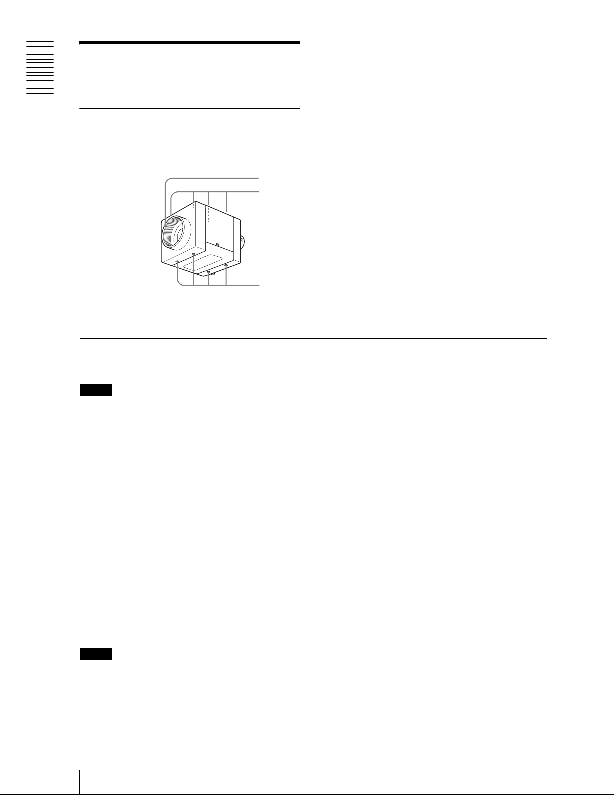
Front/Top/Bottom
1 Lens mount (C-mount)
Attach any C-mount lens or other optical equipment.
Note
The lens must not project more than 10 mm (13/32 inch)
from the lens mount.
When you use the camera with the lens attached, the
resolution of the image output from the camera may
differ according to the performance of the lens. Note it
when you select a lens.
The performance of a lens may change according to the
aperture level.
If the resolution is not enough, adjust the aperture level.
2 Guide holes (Top)
3 Reference holes (bottom)
These precision screw holes are for locking the camera
module. Locking the camera module into these holes
secures the optical axis alignment.
You can install the camera on a tripod. To install on
a tripod, you will need to install a tripod adaptor
VCT-ST70I to the camera on the reference holes
3.
Note
Refer to XCL-5000 Demensions in page 40 for about
the position/size of the Guide hole and the Reference
hole.
1
2
3
Lens mount (C-mount)
Guide holes (Top)
Reference holes (bottom)
Page 7
Overview
Location and Function of Parts and Operation
7
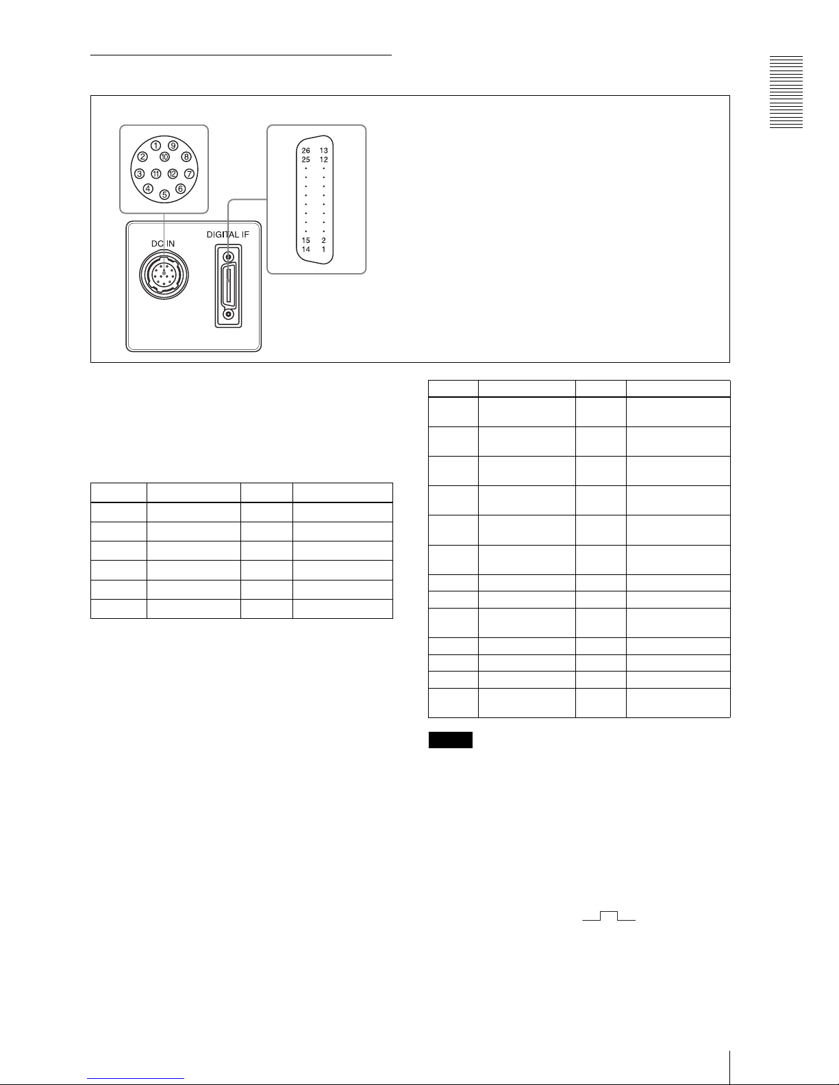
Rear
4 DC IN (DC power input) connector (12-pin)
You can connect a CCXC-12P05N camera cable to input
the +12 V DC power supply. The pin configuration of
this connector is as follows.
(For details on the pin arrangement, see the following
Figure.)
* Signal output from the Tenth pin of *12 pins
connector
You can select one of the following signals according
to the setting.
Ground / DVAL output / Exposure pules output
The default setting in the factory is Ground.
5 DIGITAL IF (Interface) connector (26-pin)
Camera Link Base Configuration: 1 tap
You can connect a Camera Link cable to this connector
to control a camera module from a host device utilizing
the serial communication protocol while outputting a
video signal from the camera module. You can input the
external trigger signal via the 26-pin connector and
operate a camera module in the external trigger mode.
The pin configuration of this connector is as follows.
(For details on the pin arrangement, see the following
Figure.)
Note
When you operate a camera module by inputting an
external trigger signal via the 26-pin connector, make
sure to input external trigger signals that meet the
following specifications to both the two pins.
Specifications for the External Trigger Signal
Amplitude: LVDS using a 3.3 volt IC
Connections: Input a TRIG (–) signal to the 9th
pin.
Input a TRIG (+) signal to the 22nd
pin.
Polarity: positive
54
4 DC IN (DC power input) connector (12-pin)
5 DIGITAL IF (Interface) connector (26-pin)
Pin No. Signal Pin No. Signal
1Ground 7NC
2 +12 V DC 8 Ground
3Ground 9NC
4 NC 10 Signal* output
5 Ground 11 Triger pulse input
6NC 12Ground
Pin No. Signal Pin No. Signal
1 INNER_SHIELD
(Ground)
14 INNER_SHIELD
(Ground)
2 X0– output
(Signal)
15 X0+ output (Signal)
3 X1– output
(Signal)
16 X1+ output (Signal)
4 X2– output
(Signal)
17 X2+ output (Signal)
5XCLK– output
(Signal)
18 XCLK+ output
(Signal)
6 X3– output
(Signal)
19 X3+ output (Signal)
7 Ser TC+ (Signal) 20 Ser TC– (Signal)
8 Ser TFG– (Signal) 21 Ser TFG+ (Signal)
9 TRIG– input
(Signal)
22 TRIG+ input
(Signal)
10 NC 23 NC
11 NC 24 NC
12 NC 25 NC
13 INNER_SHIELD
(Ground)
26 INNER_SHIELD
(Ground)
Page 8
Overview
Location and Function of Parts and Operation
8
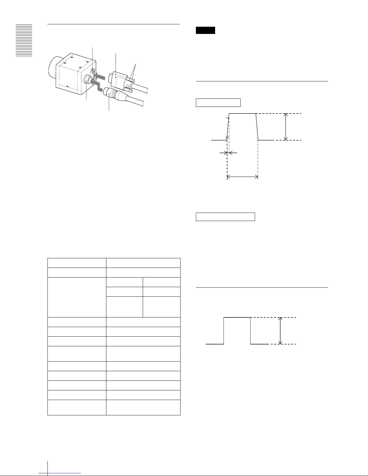
Connecting the cables
Connect the camera cable to the DC IN connector and
the Camera Link cable to the digital interface cable
respectively. When you connect the Camera Link cable,
turn the two fastening screws on the connector to secure
the cable tightly.
Connect the other end of the camera cable to the DC700/700CE and the other end of the Camera Link cable
to the camera module interface board.
Controlling the camera from the host
device
You can control the camera from host device such as a
PC. The following table shows the control functions.
You can send a command corresponding to the control
items, with parameters for the desired settings, if
necessary, from the host device to control the camera.
Refer to “Camera Control Commands” on page 29 for
details on how to send a command, the commands, and
their parameters.
Note
Make sure to supply power to the camera module and
confirm that the camera module is operating before
inputting a trigger signal. If you input trigger signal to a
camera module without the power supplied, this may
cause a mulfunction of the camera module.
Trigger signal specifications
Input impedance: Stated in the voltage determined at
more than 10 k ohms
Convert the signal which meets the specifications above
into LVDS format (3.3 V power drive IC output), and
inputs the converted signal.
Note that the signal level cannot be recognized correctly
by the camera if it does not meet the following
conditions.
H level: 1.5 V to 1.7 V
L level: 0.8 V to 1.0 V
DVAL/Exposure output specific
(only DC IN terminal)
Stated in the voltage of when terminating at more than
10 k ohms
Control functions Description
Operating mode Normal/Trigger
Shutter speed Normal 2 to 1/10000 s
Trigger edge 2 to 1/10000 s
Trigger pulse
width
Setting by
trigger pulse
width
Gain 0 to +18 dB
Binning OFF/ON
Partial Scan OFF/ON
Edge detection, Edge
emphasis
OFF/ON
Binarization OFF/ON
Gamma control OFF/MANUAL/DEFAULT
3 × 3 Image filtering OFF/ON
Video output switch 12 bits / 10 bits / 8 bits
External trigger input 26 pin connector / 12 pin
connector
2
1
3
4
5
Digital interface connector
Camera Link cable
Fastening screws
DC IN
connector Camera cable
DC IN terminal
DIGITAL IF terminal
90%
10%
2 - 5 V
10.0 μ - 2 sec
Width
0 - 0.6 V
Rising time
Less than
2.0 μsec
Amplitude
4 - 5 V
0 V
Page 9
Functions
CCD loaded on XCL-5000
9
Functions
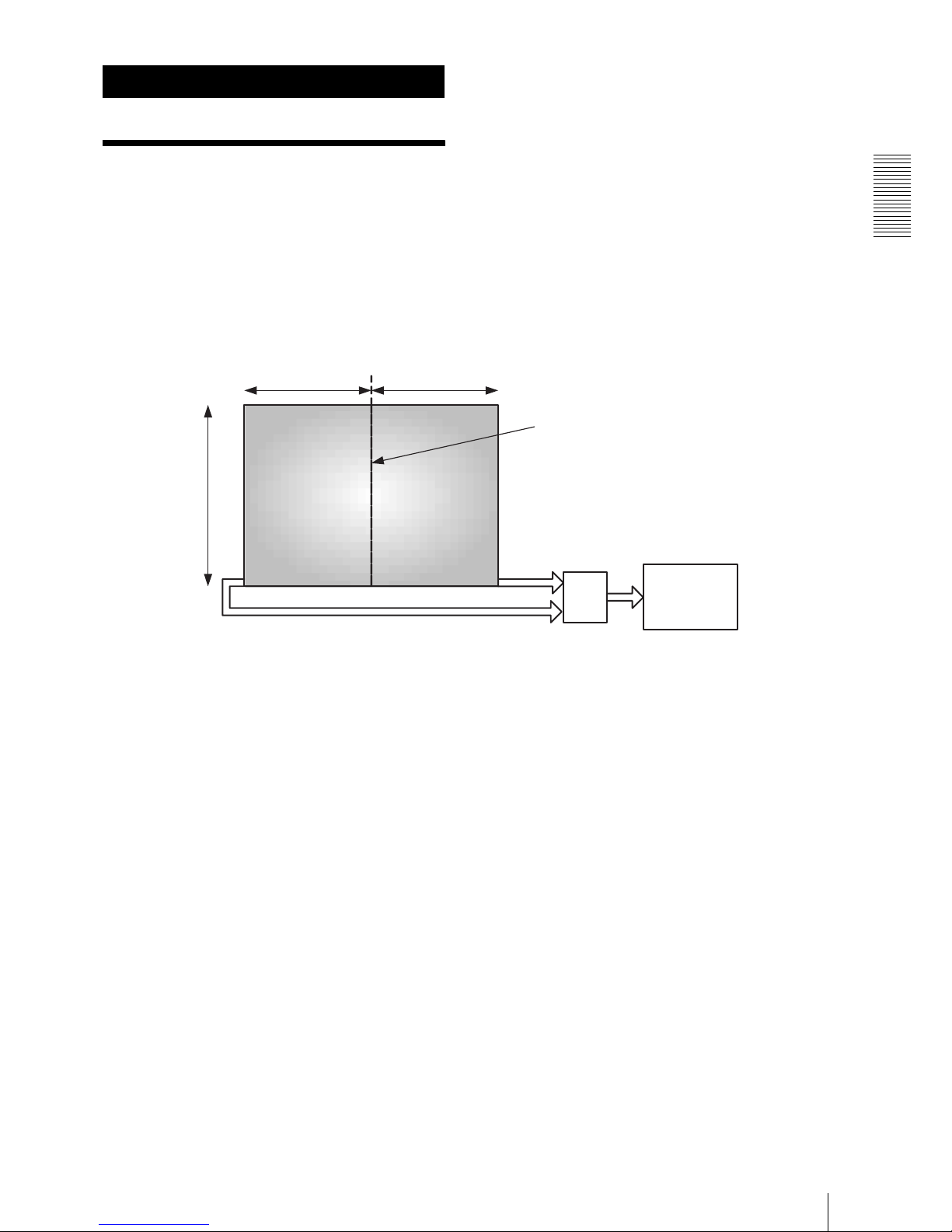
CCD loaded on XCL5000
The 500 million-pixel CCD loaded on XCL-5000 has
two signal outputs-left and right two channels output
system CCD-in order to improve the frame rate. There is
a boundary of two picking up areas in the center of the
window. The left and right signals of the boundary are
conflated into a picture by digital signal process.
Each area of the two channels output system CCD has its
output. Even so, the boundary does not appear in the
center of the window when the left and right signals are
conflated into a picture if the output characteristic
accord with each other. It is, however, very difficult for
the CCD producing technique to make two amplifier
characteristics accord completely, and the output levels
of left and right may differ. In this case, a boundary
appears in the center of the window due to the difference
of the left and right levels. XCL-5000 has an automatic
correction function that automatically detects and
corrects the difference between the levels in order to
make it indistinguishable. The automatic correction
function is set to on in the factory setting. Otherwise you
can cancel the automatic correction function and set the
correction of left and right levels manually.
A step or a boundary may be seen in the center of the
window according to the camera setting mode. This is
not a malfunction. The boundary is especially easily
seen in the Gainup.
MUX
1224 1224
2050
2448(H) × 2050(V)
Output
Boundary of picking up areas
Left Right
Left
Right
Page 10
Functions
Camera mode
10
Camera mode
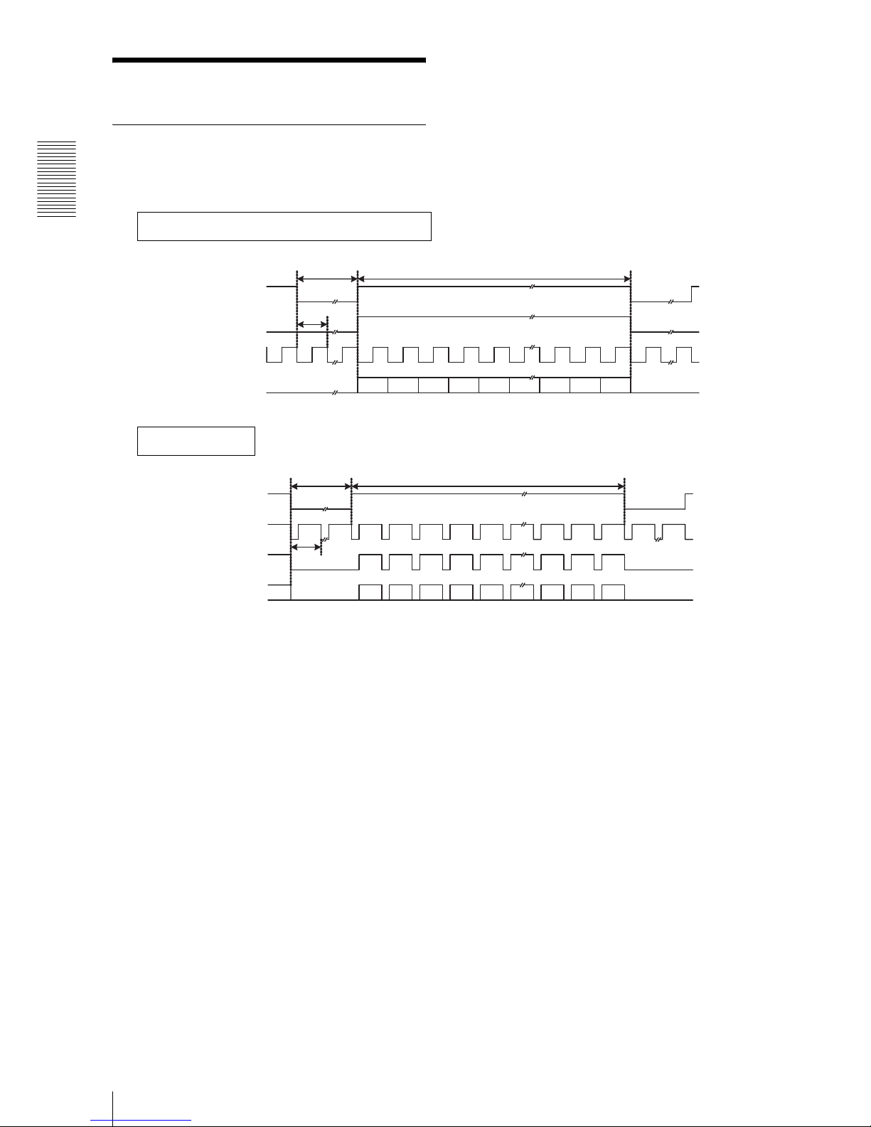
Normal mode
The output of all individual video signals is at 15 frames
per second as continuous video.
1 2 3 4 5 2446 2447 2448
72CLK
1CLK
2448CLK
1H
66H
2050H
1 2 3 4 5 2048 2049 2050
Horizontal timing: Common in each mode
1CLK=1/80MHz=12.5ns 1H=2520CLK
LVA L
DVAL
STROBE
Image output
Vertical timin g
1V=2116H
FVAL
LVA L
DVAL
Image output
Page 11

Functions
Camera mode
11
Binning mode
In this mode the frame rate almost doubles through the
addition of two vertical lines to read from the CCD.
Note
You cannot operate the camera with the binning mode
and the partial scan mode on at the same time.
1H
33H
1025H
1 2 3 4 5 1023 1024 1025
Vertical timing
1V=1058H
FVAL
LVA L
DVAL
Image output
(The horizontal timing is the same as in the normal mode.)
Page 12
Functions
Camera mode
12
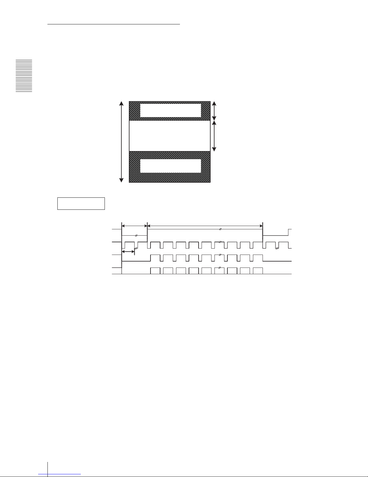
Partial scan mode
In this mode, the desired area is read out as the effective
image portion from the effective image area that is
vertically divided into approximately 16 areas, and the
redundant image area is transmitted at high speed to
increase the frame rate. Set the block numbers for highspeed transmission (Read beginning block point PSAH)
and for normal transmission (Read block number
PSAF).
Number of effective image lines
Effective image lines: 128 × (PSAF + 1) lines
PSAF: 0 to 15
When the bottom area of the window is included in the
selected area, the effective image lines decrease for the
lines of the invalid image area. The number of lines of
the invalid image is not steady. It differs according to the
value of PSAH or PSAF.
Starting/Ending point of effective image
The PSAH value of just before the effective image
starting point determines which line of the CCD
effective pixel will be the effective image starting point.
It involves fine adjustment of the timing inside the highspeed transmission length and the lines for 1 block are
not simply 128. It differs according to the PSAH value.
Also, after you have set an effective image ending point
of an area selection, if you specify this point as a starting
point of another setting, the two points may differ. This
is due to the operation principle stated above and is not
a malfunction.
Block numbers of high-speed transmission
(Read beginning block point PSAH)
Block numbers of normal transmission
(Read block number PSAF)
Whole area
1H
B
A
1 2 3 4 5 A
Vertical timing
FVAL
LVA L
DVAL
Image output
(The horizontal timing is the same as in the normal mode.)
Normal transmission length
High-speed transmission
length
High-speed transmission
length
In the Normal transmission block
1 block = 128 lines
Page 13
Functions
Camera mode
13
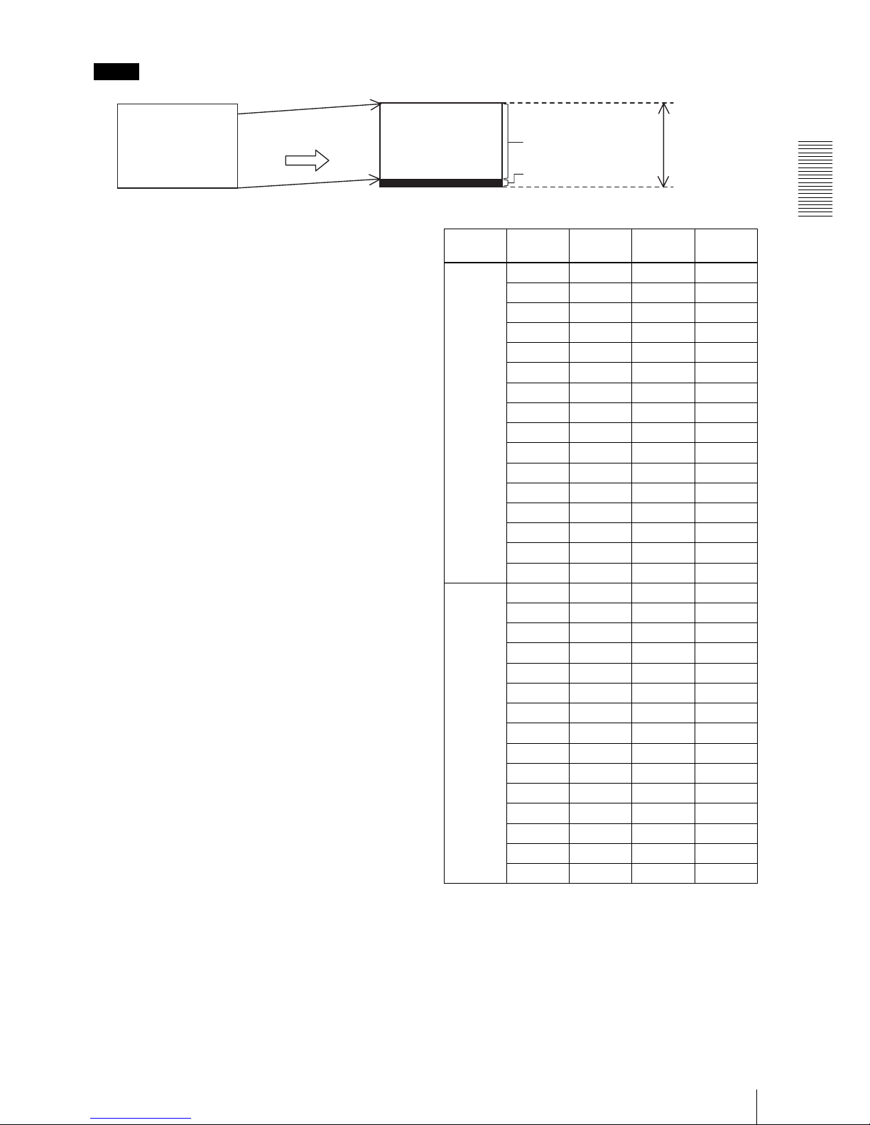
Note
In partial scan operation of this camera, the proper
image is not output for the beginning 38 lines in which
the standard black level is not steady because that CCD
is driving at high speed. For this reason, when the
normal scan mode is changed to the partial scan mode,
the effective image area is shifted up 38 lines.
Therefore in the partial scan mode, the image is
displayed 38 lines above in comparison with the normal
mode. As the result, the effective image area will be
changed and become 2016 lines. Also, when you select
the lowest area of the window in the partial scan mode,
an invalid image area (including the optical block) is
displayed in black. This is normal, not a malfunction.
When you switch the normal mode and the partial scan
mode repeatedly, if the 38-line shift described on the left
poses a problem, set to the partial scan mode instead of
the normal mode and select the whole window area in
order to use it without the image shift. In this case, the
effective image area will be 2016 lines.
Shifting up 38 lines
Effective image area
2016 lines
Invalid image area
Normal mode Partial scan mode
(When selecting the Whole area)
Normal
transmission
length
PSAH PSAF A
[LINE]B [LINE]
RATE
[fps]
0 0 128 447 55
1 256 422 47
2 384 396 41
3 512 370 36
4 640 345 32
5 768 319 29
6 896 294 27
7 1024 268 25
8 1152 242 23
9 1280 217 21
10 1408 191 20
11 1536 166 19
12 1664 140 18
13 1792 114 17
14 1920 89 16
15 2048 63 15
1 0 128 447 55
1 256 422 47
2 384 396 41
3 512 370 36
4 640 345 32
5 768 319 29
6 896 294 27
7 1024 268 25
8 1152 242 23
9 1280 217 21
10 1408 191 20
11 1536 166 19
12 1664 140 18
13 1792 114 17
14 1920 89 16
Page 14

Functions
Camera mode
14
PSAH PSAF A
[LINE]B [LINE]
RATE
[fps]
2 0 128 447 55
1 256 422 47
2 384 396 41
3 512 370 36
4 640 345 32
5 768 319 29
6 896 294 27
7 1024 268 25
8 1152 242 23
9 1280 217 21
10 1408 191 20
11 1536 166 19
12 1664 140 18
13 1792 114 17
3 0 128 447 55
1 256 422 47
2 384 396 41
3 512 370 36
4 640 345 32
5 768 319 29
6 896 294 27
7 1024 268 25
8 1152 242 23
9 1280 217 21
10 1408 191 20
11 1536 166 19
12 1664 140 18
4 0 128 447 55
1 256 422 47
2 384 396 41
3 512 370 36
4 640 345 32
5 768 319 29
6 896 294 27
7 1024 268 25
8 1152 242 23
9 1280 217 21
10 1408 191 20
11 1536 166 19
PSAH PSAF A
[LINE]B [LINE]
RATE
[fps]
5 0 128 447 55
1 256 422 47
2 384 396 41
3 512 370 36
4 640 345 32
5 768 319 29
6 896 294 27
7 1024 268 25
8 1152 242 23
9 1280 217 21
10 1408 191 20
6 0 128 447 55
1 256 422 47
2 384 396 41
3 512 370 36
4 640 345 32
5 768 319 29
6 896 294 27
7 1024 268 25
8 1152 242 23
9 1280 217 21
7 0 128 447 55
1 256 422 47
2 384 396 41
3 512 370 36
4 640 345 32
5 768 319 29
6 896 294 27
7 1024 268 25
8 1152 242 23
8 0 128 447 55
1 256 422 47
2 384 396 41
3 512 370 36
4 640 345 32
5 768 319 29
6 896 294 27
7 1024 268 25
Page 15

Functions
Camera mode
15
PSAH PSAF A
[LINE]B [LINE]
RATE
[fps]
9 0 128 447 55
1 256 422 47
2 384 396 41
3 512 370 36
4 640 345 32
5 768 319 29
6 896 294 27
10 0 128 447 55
1 256 422 47
2 384 396 41
3 512 370 36
4 640 345 32
5 768 319 29
11 0 128 447 55
1 256 422 47
2 384 396 41
3 512 370 36
4 640 345 32
12 0 128 447 55
1 256 422 47
2 384 396 41
3 512 370 36
13 0 128 447 55
1 256 422 47
2 384 396 41
14 0 128 447 55
1 256 422 47
15 0 128 447 55
Page 16

Functions
Camera mode
16
Trigger mode
In this mode video signals begin to accumulate through
synchronization with the external trigger input (12-pin
or 26-pin). The video signals are output after the
specified time has passed. Two modes are usable-the
edge detection mode, which detects the rise edge of the
external trigger signal, and the width detection mode,
which detects the effective length of the trigger. The
period of the external trigger signal cannot be set shorter
than the shutter speed. When Shutter OFF is selected,
the shutter speed is automatically set to 1/15s.
1
T1
T2
T3
2050H
2448CLK
72CLK
2050 1 2050
* T4
Vertical timing
Example of positive electrode (The horizontal timing is the same as in the normal mode.)
FVAL
LVA L
DVAL
Image output
TRG
* Only one LVAL is less than 2448CLK during T4 length in order
to adjust the timing. T4 changes by depending on T1.
Trigger mode T1 T2 Shutter T3 [ms]
Edge detection mode More than 67 msec More than 10 usec
OFF 68.16
1/15s 68.16
1/30s 34.82
1/100s 11.5
1/120s 9.82
1/250s 5.5
1/500s 3.5
1/1000s 2.5
1/2000s 2
1/5000s 1.7
1/10000s 1.6
1/7.5s 134.8
1/2s 501.5
1s 1000
2s 2000
Width detection mode More than 67 msec More than 10 usec and
less than 2 sec
– T2 + 0.52
Page 17

Functions
Camera mode
17
Trigger binning mode
In this mode the binning action begins through
synchronization with the external trigger input.
1
T1
T2
T3
1025H
2448CLK
72CLK
1025 1 1025
* T4
Vertical timing
FVAL
LVA L
DVAL
Image output
(The horizontal timing is the same as in the normal mode.)
TRG
* Only one LVAL is less than 2448CLK during T4 length in order
to adjust the timing. T4 changes by depending on T1.
Trigger mode T1 T2 Shutter T3 [ms]
Edge detection mode More than 34 msec More than 10 usec
OFF 67
1/30s 33.66
1/100s 10.32
1/120s 8.64
1/250s 4.32
1/500s 2.32
1/1000s 1.32
1/2000s 0.82
1/5000s 0.52
1/10000s 0.42
1/15s 67
1/7.5s 135.1
1/2s 509.2
1s 1000
2s 2000
Width detection mode More than 34 msec More than 10 usec
and less than 2 sec
– T2 + 0.33
Page 18

Functions
Camera mode
18
Trigger partial scan mode
In this mode the partial scan action begins through
synchronization with the external trigger input.
Set T1 in order to comply with the following formula. Refer to the partial mode regarding A and B.
T1 > 0.0315 × (A+B) [msec]
1
T1
T2
T3
A
A 1 A
* T4
2448CLK
72CLK
Vertical timing
Example of positive electrode (The horizontal timing is the same as in the normal mode.)
FVAL
LVA L
DVAL
Image output
TRG
* Only one LVAL is less than 2448CLK during T4 length in order
to adjust the timing. T4 changes by depending on T1.
Trigger mode T1 T2 Shutter T3 [ms]
Edge detection mode
See the formula under
this table.
More than 10 usec
OFF 66.86
1/15s 66.86
1/30s 33.52
1/100s 10.18
1/120s 8.52
1/250s 4.18
1/500s 2.18
1/1000s 1.2
1/2000s 0.7
1/5000s 0.4
1/10000s 0.3
1/7.5s Impossible
setting
1/2s
1s
2s
Page 19

Functions
Camera mode
19
Set T1 in order to comply with the following formula. Refer to the partial mode regarding A and B.
T1 > 0.0315 × (A+B) [msec]
Trigger mode T1 T2 Shutter T3 [ms]
Width detection mode
See the formula under
this table.
More than 10 usec and
less than 2 sec
0 T2 + 1.72
1 T2 + 2.47
2 T2 + 3.26
3 T2 + 4.36
4 T2 + 5.15
5 T2 + 5.94
6 T2 + 6.72
7 T2 + 7.51
8 T2 + 8.30
9 T2 + 9.09
10 T2 + 9.88
11 T2 + 10.66
12 T2 + 11.45
13 T2 + 12.24
14 T2 + 13.02
15 T2 + 13.81
Page 20

Functions
Shutter Setting
20
Shutter Setting
You can set the exposure time by using the electronic
shutter.
When EXPOSURE is selected for the signal output
terminal of the 12-pin connector tenth pin, Hi is output
for the exposure period.
The selectable shutter value differs according to the
mode. Refer to the following list.
a: Possible setting
–: Impossible setting
f: Possible setting according to the condition
*1 Does not use the electronic shutter. In this case, when
EXPOSURE is selected for the signal output terminal of
the tenth pin of the DC IN connector, Hi is always output.
*2 When the lines for normal transmission (PSAF) are 0 to 5,
it is Possible setting. When the lines are 6 to 15, it is
Impossible setting.
*3 The trigger signal period must be longer than the shutter
speed.
Shutter OFF is the same as 1/15s.
Normal Binning Partial Trigger (Edge detection)
*3
OFF
*1
aaa a
1/15s aa
*1
– a
1/30s aaf
*2
a
1/100s aaa a
1/120s aaa a
1/250s aaa a
1/500s aaa a
1/1000s aaa a
1/2000s aaa a
1/5000s aaa a
1/10000s aaa a
1/7.5s
*1
aa– a
1/2s aa– a
1s aa– a
2s aa– a
Page 21

Functions
DSP Operation
21
DSP Operation
Signal process block chart
As each DSP function is composed of an independent
module, DSP functions can be used in combination. For
example, you can extract the outline by using the edge
detection from an image which is processed by the
gamma correction, and then you can binarize the image.
The DSP function can be used for all camera modes.
SELSEL
Right/Left
Digital clamp
DSP input
Digital gain
Gamma
correction
3 × 3 filter
Edge detection
Edge emphasis
Binarization
Digital pedestal
Bit width
selection
Grayscale
chart
DSP output
Page 22

Functions
DSP Operation
22
Right/Left digital clamp
From –255 to +255 steps can be added to each image of
right and left area individually. The boundary in the
center of the window is due to the difference of the left
and right levels. It can be made indistinguishable by fine
adjustment of either level. This product is also equipped
with an automatic correction function (automatic clamp
control), which detects and corrects the difference
between the levels of right and left.
When the automatic correction function (automatic
clamp control) is ON, the right and left digital clamp
control cannot be used. The function is set to ON in the
factory setting.
Digital gain
In this block ×1 to ×2 (twice) (+6 dB) is processed in 128
steps,
You t = Yi n
*
factor is processed.
You can use it when the image is dark only with AFE
gain, for example.
Reference
When only the digital gain is controlled, the black level
is also changed, as the digital gain effects the whole
display level. But the black level can be retained by
subtracting in advance in the digital clamp described
previously and then adding in the digital pedestal to be
described. The output power of the digital gain is as
follows.
Yout = K × (Yin + A) + B
Input Yin
Amount of Digital
clamp subtraction
A (–255 to +255)
Digital gain factor K
Amount of digital
pedestal addition
B
Output Yout
Page 23

Functions
DSP Operation
23
Gamma correction
Set LUT discretionally, or set in the proximity line a
form supplement. Regarding the discretional setting,
enter LUT value for a discretional value from 0 to 4095.
Regarding 5 points proximity line form supplement,
select a degree from among 1 to 5 for each point (256,
512, 1024, 2048, 3072) in order to set a gamma curve
easily.
In both cases, the setting values can be saved, and can be
read in when restarting.
In the gamma mode, there are 5 modes (MODE 1 to
MODE 5) other than MODE 0. MODE 1 to MODE 4 are
MANUAL modes, MODE 5 is DEFAULT mode. When
a MANUAL mode (MODE 1 to MODE 4) is selected,
the LUT value previously saved is loaded and GAMMA
command can be accepted. When the DEFAULT mode
(MODE 5) is selected, in LUT value returns to the
factory setting and GAMMA command cannot be used.
The DEFAULT mode (MODE 5) is a gamma curve to
which the output values for 5 points (256, 512, 1024,
2048 and 3072) are set to 1, 2, 3, 3 and 3 by the 5 points
proximity line form supplement.
In MODE 2 and MODE 4 (5 points proximity line form
supplement) the gamma curve may not be in sequence.
In this case, it may seem that data lacking in a point there
is no output level after the gamma process when the
video signal is displayed in the waveform or the
histogram. This is because there is actually no signal
output corresponding to the output step value. This is not
a problem.
0
256 512 20481024 3072
OUT
IN
4095
4095
Gamma OFF
(γ = 1)
γ processed by the
line form
supplement
MODE Action immediately after
setting
ROM save LUT GAMMA
command
0OFF (γ = 1) Not saved Through (γ = 1) Impossible
1 Loads previously set value Saved Discretional setting Possible
2 Loads previously set value Saved 5 points proximity line form
supplement
Possible
3 Loads previously set value Not saved Discretional setting Possible
4 Loads previously set value Not saved 5 points proximity line form
supplement
Possible
5 Resets to initial value Saved Factory setting Impossible
Note
Page 24

Functions
DSP Operation
24
x Example of gamma command
Set the gamma mode to 1, and set level 500 to 300 and
save it.
> GAMMA-MODE 1
OK
> GAMMA 500 300
OK
Set the gamma mode to 4, then set the point “512” to
level 3 and check the picture. The setting is not saved
here. After that, set the gamma mode to 2, and save it.
> GAMMA-MODE 4
OK
> GAMMA 512 3 (Check the picture. The setting is
not saved.)
OK
> GAMMA-MODE 2
OK
> GAMMA 512 3 (The setting is saved.)
OK
Set the gamma mode to 2. You cannot set a value other
than 5 points (“256”, “512”, “1024”, “2048”, “3072”).
500 is not correct in the following.
> GAMMA-MODE 2
OK
> GAMMA 500 300
ERROR SYNTAX
OK
Turn off the gamma mode. You cannot input the
GAMMA command here.
> GAMMA-MODE 0 (Gamma mode off)
OK
> GAMMA 512 1
ERROR STATUS
Page 25

Functions
DSP Operation
25
Filter
Executes matrix operation of 3x3 pixels to add various
processes to the picture. In MODE 1, 9 filter factors can
be set to the range from –10.000 to +10.000 in 0.001
interval. In MODE 2, the regulation filter like Laplacian
can be set easily.
When MODE 1 is selected, the automatic correction
function (automatic clamp control) cannot be set to On.
x Setting example
(a) Secondary differentiation (Laplacian) filter
of 8 proximity
This filter detects an edge-a point where the contrast is
changed like the outline of the object in the picture.
(b) Picture acumination filter
A point where the contrast is changed, like an edge, is
emphasized by subtracting the secondary
differentiation. In the following filter, the Laplacian
filter of 8 proximity is multiplied by weighting factor
0.111, and then subtracting from the original image. It
emphasizes the edge by controlling the acumination
level.
12
12
FILT 11
FILT 12
FILT 13
FILT 21
FILT 22
FILT 23
FILT 31
FILT 32
FILT 33
Input Output
111
1–81
111
–0.111 –0.111 –0.111
–0.111 1.888 –0.111
–0.111 –0.111 –0.111
Page 26

Functions
DSP Operation
26
Edge detection/Emphasizing
process
Edge detection is the filter that detects an edge with
controlling noise by taking the difference of contracting
level of both sides of the original image in 4 directionsleft, right, top and bottom individually. This features
output of the clearer edge detected image.
Edge emphasis is the acumination filter which enables
adjustment of the acuminating level by setting a desired
weighting factor for the outline image made by edge
detection. An acuminated image can be displayed with
controlling noises. This is difficult only with the filter
process.
Note
In edge detection mode, the boundary of the CCD right
and left areas is rarely detected as the edge. This case
may be solved by changing the adjustment of the
automatic clamp control or turning off the automatic
clamp control temporarily.
Page 27

Functions
DSP Operation
27
Binarization
Executes the binarizion process. The threshold value can
be set in the range from 240 to 3900 (in 12 bits). When
the image output bit is changed, the range of the
threshold value setting will be 60 to 975 (in 10 bits) and
15 to 243 (in 8 bits).
Note that the threshold value setting must be converted
into a value of 12 bits even if you use the camera in 8 bits
or 10 bits.
Reference
The edge detected image can be accentuated by
combining the edge detection and the binarizion
process.
Page 28

Functions
DSP Operation
28
Digital pedestal
It can be adjusted from +1 to +255. It works to raise
whole level.
Switching image output: 8/10/12 bit
width selection
12 bits output, 10 bits output and 8 bits output can be
selected.
The factory setting is 12 bits output.
Grayscale chart
Outputs the grayscale chart instead of the video signal.
It can be used for condition setting or level check in the
current usage environment.
Y
Page 29

Camera Control Commands
General
29
Camera Control Commands
General
The XCL-5000 can be controlled externally via a serial
communication using such communication software as
“HyperTerminal” or “Tera Term”.
Serial Communication
Specifications
The serial communication system is an asynchronous
method compliant with RS-232C. The following table
shows the transmission control specifications.
Command inputs are echoed back.
Command system
Command format
To input or send a command, input a command name
and concomitant parameters setting off with spaces, and
press [Enter] (Carriage Return) key.
The following are input format and input examples.
<Input format>
command param1 param2 param3 [enter]
<Input example>
PARTIAL 1 0 15 <CR>
Notes
• Do not omit a command and parameters before the last
one. But the parameter stated inside the double
brackets like ([Parameter]) can be omitted.
Regarding the parameter without setting value, it will
be processed in the present value.
• Input alphabets are not case-sensitive.
• Input parameters of decimal number.
Command input and response
The camera returns an echo to valid inputs: letters of the
alphabet, numbers, “+”, “-”, “.”, spaces, backspaces and
[Enter] (Carriage Return).
Input of letters and symbols other than those above are
ignored.
• When command execution is completed normally,
“OK” is displayed.
<Input> PARTIAL 1 0 15 <CR>
<Window display> OK <CRLF>
• When command execution is not completed normally,
“ERROR STATUS” is displayed. Also, details of the
execution are displayed for some commands (saying
later for each command).
• If a value out of the range is input as a parameter, the
input command is invalidated and “ERROR
SYNTAX” is displayed.
<Input> PARTIAL 1 0 20 <CR>
<Window display> ERROR SYNTAX <CRLF>
• If an invalid command is input, “ERROR SYNTAX”
is displayed.
<Input> PART 1 0 20 <CR>
<Window display> ERROR SYNTAX <CRLF>
• When [Enter] key is pressed with no command input,
only the carriage return is carried out.
When an invalid letter or symbol is input, it is ignored.
Baud rate 57600 / 38400 / 19200 / 9600 [bps]
Default setting: 38400 [bps]
Data bit 8
Parity None
Stop bit 1
Flow control None
Command
category
Explanation
Camera control
command
Controls the camera.
Setting value
control command
Controls setting data saved inside
the camera.
Page 30

Camera Control Commands
Command Specification
30
Command Specification
This section describes the details of control commands
available for the XCL-5000, classified by category.
Camera control commands
The camera control commands are classified in 8
categories.
All concomitant parameter values of the camera control
commands are saved in the Flash ROM inside the
camera.
AFE Setting Command
x Gain-Step Setting
[Command] GAIN-STEP
[Parameter 1] <Gain (0 - 18)> [dB]
[Process] Sets VGA Gain of AFE.
x Gain-Step Setting (Left side of the window)
[Command] GAIN-STEP-L
[Parameter 1] <Gain (0 - 18)> [dB]
[Process] Sets VGA Gain of AFE on the left side of the
window.
x Gain-Step Setting (Right side of the window)
[Command] GAIN-STEP-R
[Parameter 1] <Gain (0 - 18)> [dB]
[Process] Sets VGA Gain of AFE on the right side of the
window.
x Gain-Fine Setting
[Command] GAIN-FINE
[Parameter 1] <Gain (0 - 502)>
[Process] Divides the range from 0 to 18 dB of “Gain-
Step setting” into 502 parts, and fine adjusts VGA
Gain of AFE and sets them.
x Gain-Fine Setting (Left side of the window)
[Command] GAIN-FINE-L
[Parameter 1] <Gain (0 - 502)>
[Process] Divides the range from 0 to 18 dB of “Gain-
Step setting” into 502 parts, and fine adjusts VGA
Gain of AFE on the left side of the window and sets
them.
x Gain-Fine Setting (Right side of the window)
[Command] GAIN-FINE-R
[Parameter 1] <Gain (0 - 502)>
[Process] Divides the range from 0 to 18 dB of “Gain-
Step setting” into 502 parts, and fine adjusts VGA
Gain of AFE on the right side of the window and sets
them.
x Pedestal Setting
[Command] PEDESTAL
[Parameter 1] <Pedestal level (0 - 1023)>
[Process] Sets AFE pedestal level.
x Pedestal Setting (Left side of the window)
[Command] PEDESTAL-L
[Parameter 1] <Pedestal level (0 - 1023)>
[Process] Sets AFE pedestal level on the left side of the
window.
x Pedestal Setting (Right side of the window)
[Command] PEDESTAL-R
[Parameter 1] <Pedestal level (0 - 1023)>
[Process] Sets AFE pedestal level on the right side of the
window.
x Shutter Speed Setting
[Command] SHUTTER
[Parameter] <Shutter setting (0 - 14)>
0: OFF 5: 1/250s 10: 1/10000s
1: 1/15s 6: 1/500s 11: 1/7.5s
2: 1/30s 7: 1/1000s 12: 1/2s
3: 1/100s 8: 1/2000s 13: 1s
4: 1/120s 9: 1/5000s 14: 2s
[Process] Sets the shutter speed.
x Trigger Mode Setting
[Command] TRG-MODE
[Parameter 1] <Mode (0 - 2)>
0: OFF
t Normal output of moving picture
1: External trigger/Edge detection
t Controls the shutter speed beginning
exposure from the valid edge of the external
trigger.
2: External trigger/Pulse width detection
t Controls the shutter speed with the valid
pulse width of the external trigger.
[Process] Sets the trigger operation mode.
Category Explanation
AFE Executes setting of AFE.
Shutter / Trigger Executes settings connected to
Shutter/Trigger function.
DTL /
Binarization
Executes setting of DTL/
Binarization.
Digital Executes setting connected to digital
processes.
Gamma Executes setting of Gamma
correction curve.
Filter Executes setting of Filter.
Binning / Partial Executes settings of Binning/Partial.
IN / OUT Executes settings connected to
input/output of the camera.
Page 31

Camera Control Commands
Command Specification
31
x External Trigger Pulse Polarity Setting
[Command] TRG-POL
[Parameter 1] <Mode (0 - 1)>
0: Negative
1: Positive
[Process] Specifies the polarity of the external trigger
pulse.
DTL/Binarization Setting Command
x Edge Emphasis Filter Factor Setting
[Command] DTL-COEF
[Parameter 1] <Mode (0 - 15)>
[Process] Sets the edge emphasis filter factor.
x DTL Mode Setting
[Command] DTL-MODE
[Parameter 1] <Mode (0 - 2)>
0: OFF
1: Edge detection filter
2: Edge emphasis filter
[Process] Sets the DTL mode. Regarding the edge
emphasis filter, the edge emphasis filter factor is
reflected.
Note
While setting the DTL 1 and DTL 2, the Clamp
convergence threshold value (Parameter 2) of the Auto
clamp control setting (Automatic correction function)
cannot be changed.
x Binarization Threshold Value Setting
[Command] BINARIZE
[Parameter 1] <Mode (0 - 1)>
0: OFF
1: ON
([Parameter 2])<Binarization threshold value (240 -
3900)>
[Process] Sets the binarization mode and the
binarization threshold value.
Digital Setting Command
x Digital/Y gain Setting
[Command] DGAIN
[Parameter 1] <Mode (0 - 1)>
0: OFF
1: ON
[Process] Sets the DSP digital and Y gain.
x Digital/Y gain-Step Setting
[Command] DGAIN-STEP
[Parameter 1] <Gain (0 - 128)>
[Process] Sets and fine adjusts the DSP digital and Y
gain.
x Digital/Pedestal Setting
[Command] DPEDESTAL
[Parameter 1] <Mode (0 - 1)>
0: OFF
1: ON
([Parameter 2])<Pedestal level (0 - 255)>
[Process] Sets the digital/pedestal level.
x Automatic Clamp Control Setting (Automatic
Correction Function)
[Command] AUTO-DCLAMP
[Parameter 1] <Mode (0 - 1)>
0: OFF
1: ON
([Parameter 2])<Clamp convergence threshold value (0
- 65535)>
[Process] Sets the automatic clamp control and the
clamp convergence threshold value.
x Digital Clamp Setting
[Command] DCLAMP
[Parameter 1] <Mode (0 - 1)>
0: OFF
1: ON
([Parameter 2])<Clamp adjusting value (± 255)>
[Process] Sets the digital clamp and the clamp adjusting
value.
x Digital Clamp Setting (Right side of the
window)
[Command] DCLAMP-R
[Parameter 1] <Mode (0 - 1)>
0: OFF
1: ON
([Parameter 2])<Clamp adjusting value (± 255)>
[Process] Sets the digital clamp and the clamp adjusting
value on the right side of the window.
x Digital Clamp Setting (Left side of the
window)
[Command] DCLAMP-L
[Parameter 1] <Mode (0 - 1)>
0: OFF
1: ON
([Parameter 2])<Clamp adjusting value (± 255)>
[Process] Sets the digital clamp and the clamp adjusting
value on the left side of the window.
Page 32

Camera Control Commands
Command Specification
32
Gamma Setting Command
x γ Mode Setting
[Command] GAMMA-MODE
[Parameter 1] <Mode (0 - 5)>
0: OFF
1: Optional setting
2: 5 points approximation
3: Optional setting (Setting value is not saved.)
4: 5 approximation points (Setting value is not
saved.)
5: Default setting
[Process] Sets the γ mode.
Setting γ mode 5 sets the default value.
x γ Table Setting (the case of γ mode 1 and 3)
[Command] GAMMA
[Parameter 1] <IN data (0 - 4095)>
[Parameter 2] <OUT data (0 - 4095)>
[Process] Sets the γ table optionally.
x γ Table Setting (the case of γ mode 2 and 4)
[Command] GAMMA
[Parameter 1] <Changing point (256 / 512 / 1024 / 2048
/ 3072)>
[Parameter 2] <Strong and weak (1 - 5)>
[Process] Sets the γ table at the 5 approximation points.
Filter Setting Command
x Filter Mode Setting
[Command] FILTER-MODE
[Parameter 1] <Mode (0 - 2)>
0: OFF
1: Optional setting
2: Table setting
[Process] Sets the filter mode.
x Filter Setting (the case of filter mode 1)
[Command] FILTER
[Parameter 1] <Address (11 / 12 / 13 / 21 / 22 / 23 / 31 /
32 / 33)>
[Parameter 2] <Filter factor (± 0.000 – ±10.000)>
[Process] Sets the filter optionally.
x Filter Setting (the case of filter mode 2)
[Command] FILTER
[Parameter 1] <Table (1 - 6)>
[Process] Sets the filter table.
Binning / Partial Setting Command
x Binning Mode Setting
[Command] BINNING
[Parameter 1] <Mode (0 - 1)>
0: OFF
1: ON
[Process] Sets the binning mode.
x Partial Scan Setting
[Command] PARTIAL
[Parameter 1] <Mode (0 - 1)>
0: OFF
1: ON
([Parameter 2])<Read beginning block point (0 - 15)>
([Parameter 3])<Read block number>
[Process] Sets the mode of Partial scan in parameter 1,
and specifies the read area of the partial scan
operation in parameter 2 and 3.
The range of setting values is as follows. Any other
value is invalid.
⏐Read beginning block point + Read block number⏐
<=15
IN/OUT Setting Command
x External Trigger Signal Input Selection
[Command] EXTTRG
[Parameter 1] <Input specification (0 - 1)>
0: Camera Link
t Camera Link via connector
1: DC
t DC via connector
[Process] Selects an input route of the external trigger
signal.
x Built-in Grayscale Output Setting
[Command] GRAYSCALE
[Parameter 1] <Mode (0 - 1)>
0: OFF
1: ON
[Process] Sets ON/OFF of the built-in grayscale mode.
x DC12Pin Signal Output Setting
[Command] WEN-STRB
[Parameter 1] <Specification for 12 pin output (0 - 2)>
0: GND output
1: DVAL output
2: EXPOSURE output
[Process] Sets the DC 12 Pin signal output specification.
x Image Output Data Width
[Command] IMG-WIZE
[Parameter 1] <Image output data width (0 - 2)>
0: 12bit output
1: 10bit output
2: 8bit output
[Process] Sets the image output data width.
Page 33

Camera Control Commands
Command Specification
33
x Serial Transmission Speed Setting
[Command] BRATE
[Parameter 1] <Baud rate (0 - 3)>
0: 9600bps
1: 19200bps
2: 38400bps
3: 57600bps
[Process] Sets the serial transmission speed.
Setting Value Control Command
The setting value control command controls camera
setting data saved in the Flash ROM inside the camera.
The following list shows the contents.
Setting Initialization Command
Note
Some data are not initialized by executing the following
commands. For details, refer to “Parameter List” on
page 37.
x Initialization of Setting
[Command] INIT
[Process] Initializes the data corresponding to the
camera control command to the factory setting value.
Save Setting Command
x Save Setting
[Command] SAVE
[Process] Writes the data corresponding to the camera
control command in the Flash ROM.
Another command is not accepted during execution of
the process. After completion of execution, the
following message is displayed.
“OK”: Normal completion
Note
If the completion is not normal, the saved data may be
damaged.
Read Setting Command
x Read Setting
[Command] LOAD
[Process] Reads the data corresponding to the camera
control command in the Flash ROM.
Command Explanation
Initialization
of setting
value
Initializes the data corresponding to the
camera control command to the factory
setting value.
Save setting Writes the data corresponding to the camera
control command in the Flash ROM.
Read setting Reads the data corresponding to the camera
control command in the Flash ROM.
Setting value
accession
Sends the necessary data to the camera
control application.
Page 34

Camera Control Commands
Command Specification
34
Setting Value Accession Command
x Setting Value Accession
[Command] RMEM
[Parameter 1] <Setting value selection (None, 1 - 2)>
None: Camera setting value accession
1: Filter factor accession
2: γ table value accession
[Process] Sends the data which can be set by Serial
communication and the camera information
(version) to the camera control application.
Another command is not accepted during
transmission of data.
[Data transmission] Transmits data continuously in each
category.
The transmitting data are shown in decimal number.
The followings are transmission format and the
transmission examples.
<Transmission format>
<Category>: <Data 1>, <Data 2>, <Data 3>, ...,
<CRLF>
<Transmission example>
CA: 1.00 <CRLF>
AF: 0, 0, 1023, 1023, ..., <CRLF>
SH: 0 <CRLF>
.
.
.
OK <CRLF>
Gamma setting can get a setting value only when it is set
by the 5 points proximity (γ mode 2 and 4).
Category
name
Content Data
numbers
Data
CA Camera
information
1<Version>
AF AFE 4 <AFE Gain-left>, <AFE Gain-right>, <Clamp level-left>, <Clamp level-right>
SH Shutter 1 <Shutter speed>
TR Trigger 2 <Trigger mode>, <External trigger pulse polarity>
DT DTL 2 <DTL mode>, <Edge emphasis filter factor>
BR Binarization 2 <Binarization mode>, <Binarization threshold value>
DG Digital 10 <Digital/Y Gain mode>, <Digital/Y Gain step>, <Digital/Pedestal mode>,
<Digital/Pedestal>, <Automatic clamp control setting>, <Automatic clamp
control threshold value>, <Digital/Clamp mode-left>, <Digital/Clamp-left>,
<Digital/Clamp mode-right>, <Digital/Clamp-right>
GM Gamma 6 <γ mode>, <Change point (256)>, <Change point (512)>, <5 Change point
(1024)>, <Change point (2048)>, <Change point (3072)>
FL Filter 1 <Filter mode>
BN Binning 1 <Binning mode>
PT Partial 3 <Partial scan mode>, <Partial scan read beginning block point>, <Partial scan read
block number>
IO IN / OUT 5 <Trigger signal input selection>, <Built-in grayscale output mode>, <Image
output data width>, <DC12Pin signal output setting>, <Serial communication
speed setting>
Page 35

Camera Control Commands
Command Specification
35
Others
x Version Indication
[Command] VERSION
[Process] The camera model name and the camera
version are displayed
<Input> VERSION<CR>
<Window display> XCL-5000 Ver.
*.**
<CRLF>
OK<CRLF>
x Help Indication
[Command] HELP
[Process] The list of camera control commands is
displayed.
Command Limitation
Even a valid parameter can be invalid in combination
with some settings. In this case, the command is invalid
and “ERROR STATUS” is displayed.
Shutter speed condition
Filter mode (Mode 1 only)
Partial scan mode
Partial scan read block
numbers
Shutter speed setting
0 - 5 1/100 to 1/10000
6 - 15 1/30 to 1/10000
Automatic Clamp
Control Setting
(Automatic Correction
Function)
Filter mode 1
OFF Setting is possible.
ON Setting is not possible.
Binning mode Partial scan mode
OFF Setting is possible.
ON Setting is not possible.
Page 36

Camera Control Commands
Command List
36
Command List
The following is the list of camera control commands.
Command Parameter 1 Parameter 2 Parameter 3 Explanation
GAIN-STEP Gain – – Gain-step setting
GAIN-STEP-L Gain – – Gain-step setting
GAIN-STEP-R Gain – – Gain-step setting
GAIN-FINE Gain – – Gain-fine setting
GAIN-FINE-L Gain – – Gain-fine setting
GAIN-FINE-R Gain – – Gain-fine setting
PEDESTAL Clamp level – – Clamp level setting
PEDESTAL-L Clamp level – – Clamp level setting
PEDESTAL-R Clamp level – – Clamp level setting
DGAIN Mode – – Digital/Y gain mode setting
DGAIN-STEP Y gain – – Digital/Y gain-step setting
DPEDESTAL Mode Pedestal level – Digital/pedestal setting
AUTO-DCLAMP Mode Clamp convergence
threshold value
– Automatic clamp control setting
DCLAMP Mode Clamp level – Digital/clamp level setting
DCLAMP-L Mode Clamp level – Digital/clamp level setting
DCLAMP-R Mode Clamp level – Digital/clamp level setting
SHUTTER Shutter setting – – Shutter speed setting
TRG-MODE Mode – – Trigger mode setting
TRG-POL Pulse polarity – – External trigger polarity setting
DTL-MODE Mode – – DTL mode setting
DTL-COEF Filter factor – – Edge emphasis filter factor setting
IMG-WIZE Data width – – Image data width setting
GAMMA-MODE Mode – – γ mode setting
GAMMA
(MODE1, 3)
(MODE2, 4)
IN data
Changing point
OUT data
Strong and weak
–
–
γ table setting
γ table setting
FILTER-MODE Mode – – Filter mode setting
FILTER
(MODE1)
(MODE2)
Address
Tab le
Filter factor
–
–
–
Filter table setting
Filter table setting
BINARIZE Mode Binarization
threshold value
– Binarization mode, Binarization
threshold value setting
BINNING Mode – – Binning mode setting
PARTIAL Mode Read beginning
block point
Read block numbers Partial scan setting
EXTTRG Trigger selection – – External trigger signal input selection
GRAYSCALE Mode – – Grayscale output setting
WEN-STRB Signal output
selection
– – DC 12 Pin signal output setting
BRATE Baud rate – – Serial communication speed setting
INIT – – – Initialization of setting
SAVE – – – Save setting
LOAD–––Read setting
RMEM – – – Setting value accession
VERSION – – – Version indication
HELP – – – Help indication
Page 37

Camera Control Commands
Parameter List
37
Parameter List
The following is the camera initial value parameter list.
*1 PEDESTAL is initialized to the factory setting value by
the setting initialization command INIT. The factory
setting value cannot be given because it differs for each
camera.
*2 Parameters included in ( ) are not be initialized by the
setting initialization command INIT.
Command Parameter 1 Parameter 2 Parameter 3 Explanation
GAIN-STEP 0 – – Gain-step setting
GAIN-FINE 0 – – Gain-fine setting
PEDESTAL [Peculiar value of
the camera]
*1
– – Clamp level setting
DGAIN OFF – – Digital/Y gain mode setting
DGAIN-STEP 0 – – Digital/Y gain-step setting
DPEDESTAL OFF 32 – Digital/pedestal setting
AUTO-DCLAMP ON (8192)
*2
– Automatic clamp control setting
DCLAMP OFF – – Digital/clamp level setting
SHUTTER 0 – – Shutter speed setting
TRG-MODE OFF – – Trigger mode setting
TRG-POL 1: Straight polarity – – External trigger polarity setting
DTL-MODE OFF – – DTL mode setting
DTL-COEF (8)
*2
– – Outline emphasis filter factor setting
IMG-WIZE 0: 12 bit – – Image data width setting
GAMMA-MODE OFF – – γ mode setting
FILTER-MODE OFF – – Filter mode setting
BINARIZE OFF (1911)
*2
– Binarization mode, Binarization
threshold value setting
BINNING OFF – – Binning mode setting
PARTIAL OFF 0 0 Partial scan setting
EXTTRG 0: CameraLink – – External trigger signal input selection
GRAYSCALE OFF – – Grayscale output setting
WEN-STRB 0: GND output – – DC12Pin signal output setting
BRATE 2: 38400 bps – – Serial communication speed setting
Page 38

Specifications
Specifications
38
Specifications
Specifications
Imaging system
Pickup device Progressive scan 2/3 type CCD
Effective picture elements (horizontal/vertical)
2456 × 2058
Optical blank 40 elements on each horizontal line
Cell size (horizontal/vertical)
3.45 × 3.45 µm
Chip size (horizontal/vertical)
9.93 × 8.70 mm
Optical system and others
Lens mount C-mount
Flange focal length
17.526 mm
Synchronization
Internal
Video output 12 bits/10 bits/8 bits LVDS switching
Reference video output level:
3760 steps (12 bits)
Reference pedestal level:240 steps (12 bits)
Range of guarantee video output:
240 to 3900 steps (12 bits)
Output signal frequency
15 Hz (normal mode)
Effective lines 2448 × 2050 (horizontal/vertical)
Horizontal resolution
Equivalent to 1800 TV lines or more
Sensitivity 400 lx, F5.6 (0 dB)
Minimum illumination
1 lx (with the gain control at +18 dB,
F1.4)
Gain 0 to +18 dB
Gamma OFF/MANUAL/DEFAULT
Read mode normal/binning
Shutter External trigger shutter
Shutter speed External trigger shutter: 2 to 1/10000
sec.
Power +12 V DC (Range: +10.5 to 15 V)
Power consumption
3.6 W
Operating temperature:
–5 to +45 °C (23 to 113 °F)
Storage temperature:
–30 to +60 °C (–22 to +140 °F)
Operating relative humidity:
20 to 80 % (no condensation)
Storage relative humidity:
20 to 95 % (no condensation)
Vibration resistance
10 G (20 Hz to 200 Hz)
Shock resistance
70 G
External dimension (w/h/d)
44 × 44 × 57.5 mm
(1
3
/4 × 1 3/4 × 2 3/8 inches)
Mass Approx. 135 g (Approx. 4.8 oz)
MTBF 67,900 hours (Approx. 7.75 years)
Accessories Lens mount cap (1)
Operating Instructions (1)
Design and specifications are subject to change without
notice.
IMPORTANT
The nameplate is located on the bottom.
Page 39

Specifications
Spectral Sensitivity Characteristics (Typical Values)
39
Spectral Sensitivity
Characteristics (Typical
Values)
0.0
400
500 600
700
800 900 1000
0.1
0.2
0.3
0.4
0.5
0.6
0.7
0.8
0.9
1.0
Relative
Response
Wave Length [nm]
(Lens characteristics included, and light source
characteristics excluded.)
Page 40

Specifications
XCL-5000 Dimensions
40
XCL-5000 Dimensions
DC IN
DIGITAL IF
5Mega
CCD
XCL-5000
Unit: mm (inches)
4-M3
50 (2)13
(
17
/32)
57.5 (2
3
/8)
8
(
11
/32)
50 (2)13
(
17
/32)
4-M3
44 (1
3
/4)
44 (1
3
/4)
φ28.5 (1
1
/8)
26 (1
1
/16)
26 (1
1
/16)
Page 41

Sony reserves the right to change specifications of the products and discontinue products without notice.
Technical information contained herein is for reference only and does not convey any license by any implication or
otherwise under any intellectual property right or other right of Sony or third parties.
Sony cannot assume responsibility for any right infringements arising out of the use of this information.
Sony Corporation
 Loading...