

Page 1
A-CKD-100-11(1)
CCD Black-and-White
Video Camera Module
Technical Manual
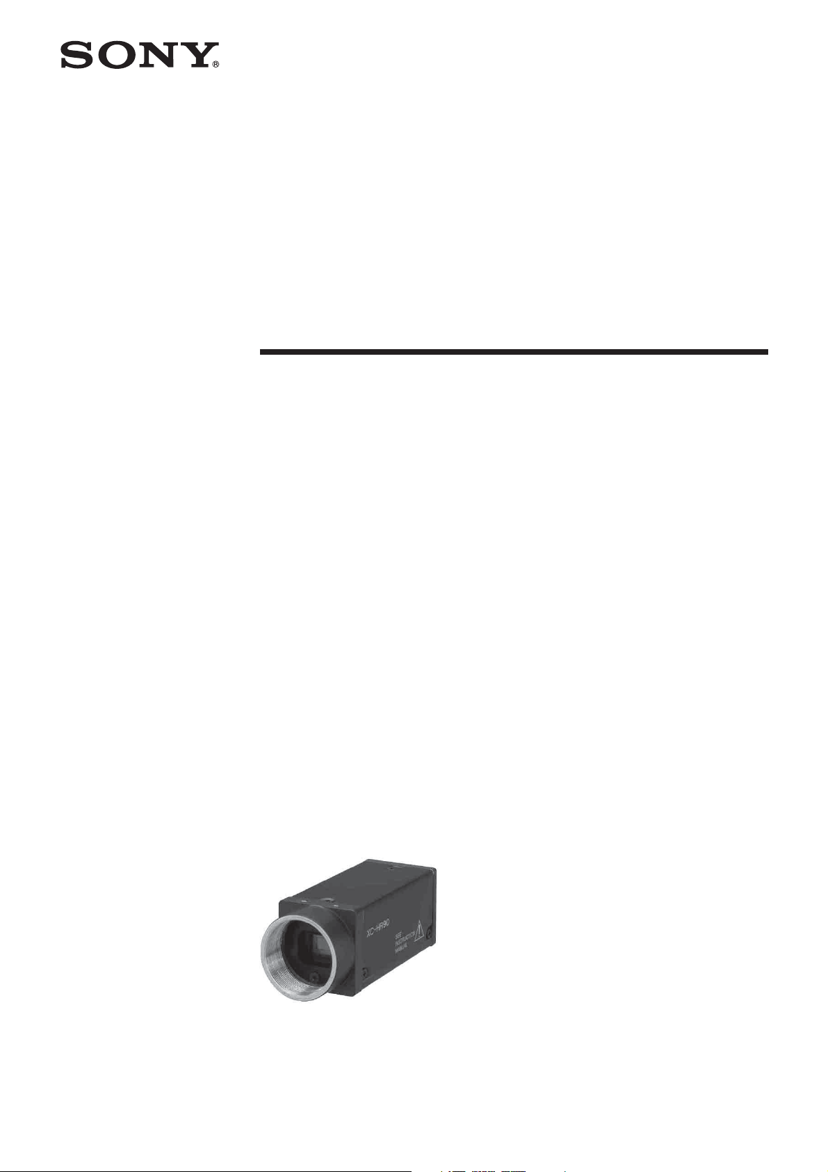
XC-HR90
2006 Sony Corporation
Page 2

Table of Contents
Overview
Mode Settings
Features ..................................................................... 3
System Components ................................................. 4
Connection Diagram ................................................. 4
Location and Function of Parts and Controls ........ 5
Front/Top/Bottom ........................................................ 5
Rear Panel ................................................................. 6
Input/Output Specifications ................................... 10
External HD/VD Input Specifications ........................ 10
External HD/VD Output Specifications ..................... 10
WEN Output Specifications ...................................... 10
VD Input Specifications ............................................ 11
HD Input Specifications ............................................ 11
Tr igger Pulse Specifications ..................................... 11
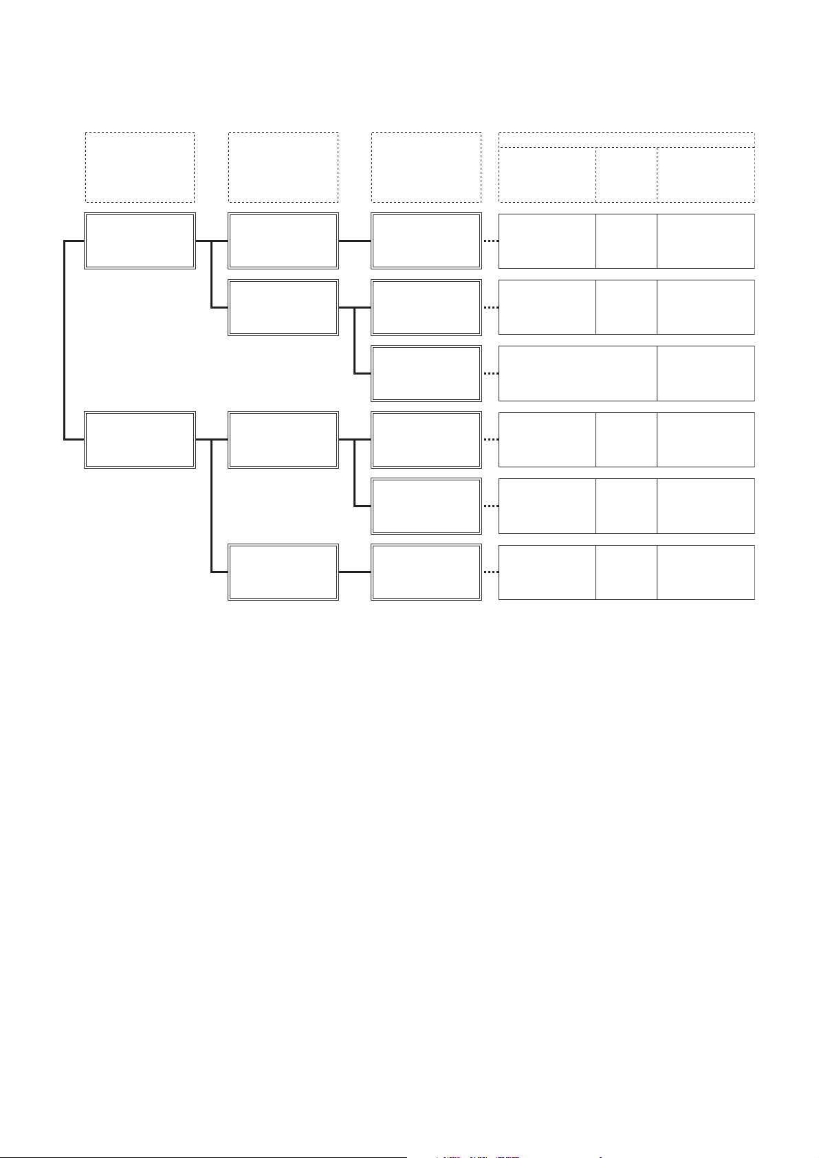
Mode System Diagram ............................................. 12
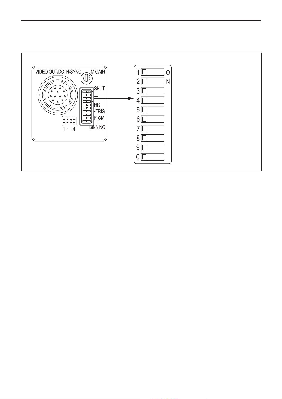
Mode Setting DIP Switches .................................... 13
Video Output Modes ............................................... 14
Binning OFF ............................................................. 14
Binning ON ............................................................... 14
About the Electronic Shutter .................................. 15
Normal Shutter ........................................................ 16
30 fps Mode.............................................................. 17
15 fps Mode.............................................................. 18
Restart/Reset ........................................................... 19
Setting Restart/Reset Mode ..................................... 19
Partial Scan Mode ................................................... 20
Timing Chart for Partial Scan Mode (Internal Synchro-
nization) ................................................................. 21
External Trigger Shutter .......................................... 22
Setting the External Trigger Shutter ......................... 23
Timing Chart ............................................................. 25
Camera Control Command
Specifications
Overview .................................................................. 32
Serial Communication Specifications ....................... 32
Command Format .................................................... 32
Command Input and Response................................ 32
Command Specifications ....................................... 33
Main Specifications ................................................. 35
Spectral Sensitivity Characteristics
(Typical Values) ..................................................... 36
Horizontal Output Waveform Timing Chart ........... 37
Vertical Output Waveform Timing Chart ................ 39
Dimensions .............................................................. 41
2
Page 3

Overview
Overview
The XC-HR90 is a black-and-white video camera
module using a CCD (Charge Coupled Device) image
sensor.
Features
High image quality
The 1,300,000-pixel SXGA-compatible CCD image
sensor delivers detailed images with the equivalent of
SXGA resolution (1280 × 960 pixels). The CCD has
square pixels, eliminating the need for aspect ratio
conversion.
Various mode settings
Rear panel switches, or sending a command from the
host device (e.g., PC) allow the following mode
settings.
•Gain: Fixed/Manual
•Read mode (30 fps): Normal (30 fps)/Binning
(54.1fps)
•Read mode (15 fps): Normal (15 fps)/Binning (30fps)
• Partial scan
• Synchronized input/output
•75Ω termination
• Shutter modes: Normal/Trigger shutter
• Shutter speed
Electronic shutter
You can choose a shutter speed from a wide range of
image speeds (1/100 to 1/100,000 s) for the best match
to shooting conditions.
External trigger shutter function (1/4 to
1/100,000 s)
You can obtain a freeze picture by inputting an
external trigger. This function is useful for shooting a
fast-moving object at a precise moment.
Partial scan
By limiting the number of effective image output lines,
you can obtain image output at high frame rates,
suitable for high-speed image processing.
Binning function
Video signals combining vertically adjacent lines can
be obtained at following frame rate.
In read mode (30 fps): 54.1 fps
In read mode (15 fps): 30 fps
Mounting holes
External synchronization
The camera module automatically detects HD
(horizontal drive) and VD (vertical drive) signals input
for external synchronization.
External sync signal output
You can output HD and VD signals from a 12-pin
connector by changing the setting of a rear panel
switch.
Mounting screw holes are provided on the reference
plane on the lower surface of the body, allowing
mounting for minimum deviation in the optical axis.
Compliant with EIAJ 12-pin connector pin
assignments
The pin arrangement adds pin assignments for trigger
pulses and WEN signals.
3
Page 4
System Components
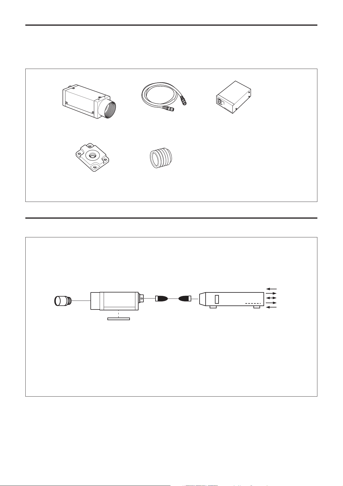
The XC-HR90 Video Camera Module system is
comprised of the following components.
Overview
Camera cables (not supplied)
Video camera module
XC-HR90
Tripod adaptor (not supplied)
VCT-55I
(Insulated type)
CCXC-12P02N(2 m)
CCXC-12P05N(5 m)
CCXC-12P10N(10 m)
CCXC-12P25N(25 m)
Connection Diagram
Camera adaptor (not supplied)
DC-700/700CE
C-mount lens (not supplied)
(Our company does not handle the
C-mount lens for this camera.)
C-mount lens
XC-HR90
Tripod adaptor
VCT-55I
Camera cables
CCXC-12P02N
CCXC-12P05N
CCXC-12P10N
CCXC-12P25N
AC
VIDEO OUT
HD/VD
WEN
TRIG
Camera adaptor
DC-700/700CE
(Conforms to EIAJ 12-pin
assignments)
4
Page 5
Location and Function of Parts and Controls
Front/Top/Bottom
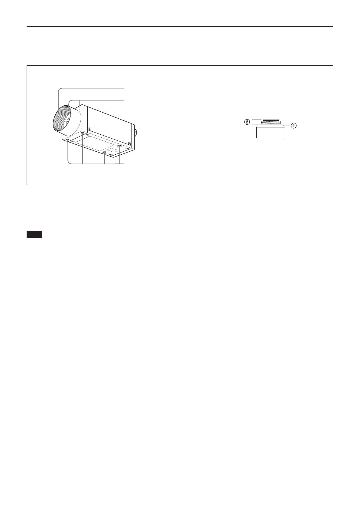
1 Lens mount (C-mount)
2 Auxiliary screw holes (at the top)
3 Reference screw holes/Tripod adaptor screw holes (at the
bottom)
Overview
1 Lens mount (C-mount)
Attach any C-mount lens, which is suitable for SXGA
for high resolution, or other optical equipment.
Note
The lens must not project more than 10 mm (13/32
inch) from the lens mount.
1 Lens mount face
2 10 mm (13/32 inches) or less
2 Auxiliary screw holes (at the top)
3 Reference screw holes/Tripod adaptor screw
holes (at the bottom)
These precision screw holes are for locking the camera
module. Locking the camera module using these holes
secures the optical axis alignment.
You can install the camera on a tripod. To install on a
tripod, you will need to install the VCT-55I tripod
adaptor using the reference holes on the bottom of the
camera.
5
Page 6
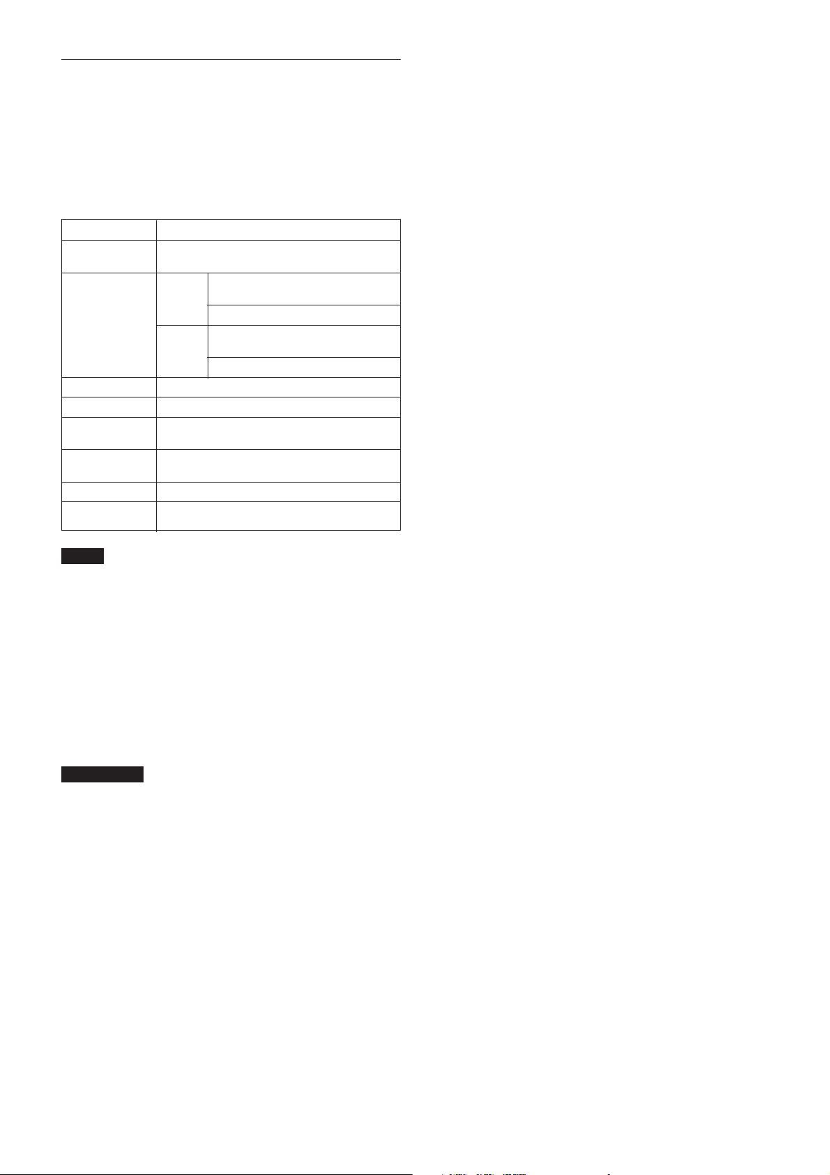
Rear Panel
Overview
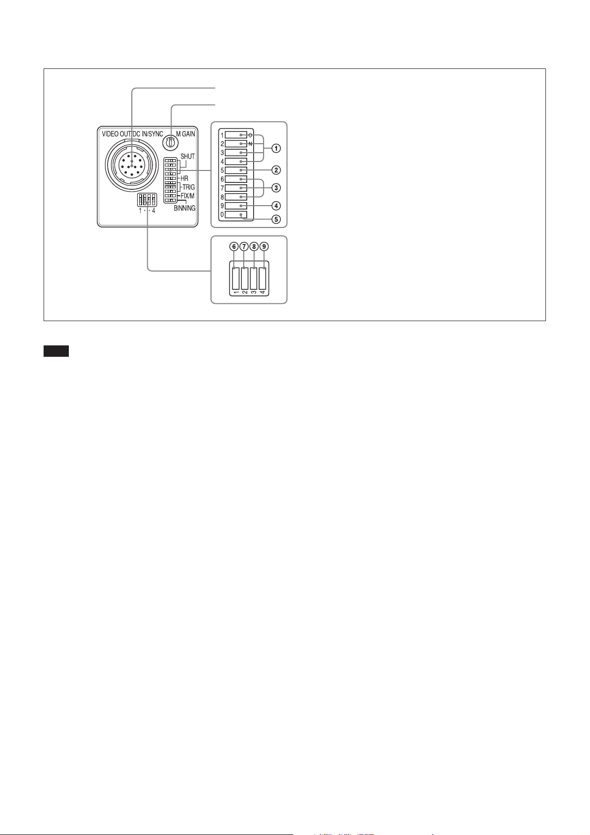
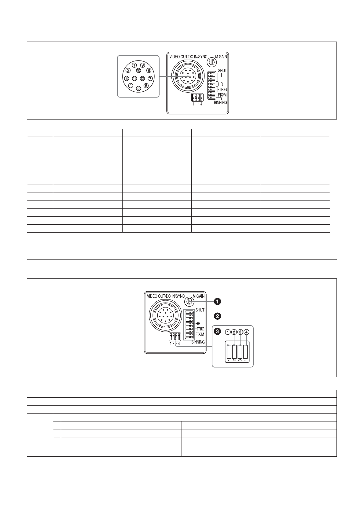
1 VIDEO OUT/DC IN/SYNC connector
2 M Gain control knob
3 Shutter speed / mode setting DIP switches
4 Mode setting DIP switches
Note
Be sure to turn the power off before making switch
settings.
1 VIDEO OUT/DC IN/SYNC (video output/DC
power/sync input signal) connector (12-pin
connector)
Connect a CCXC-12P05N camera cable to this
connector to obtain power from the +12V DC power
supply and also to enable video signal output from the
camera module. When a sync signal generator is
connected to this connector, the camera module is
synchronized with the external sync signals (HD/VD
signals).
2 M GAIN (Manual Gain) control knob
If you have selected MANUAL (manual adjustment)
with DIP switch 4, this knob adjusts the gain.
3 Shutter speed/Mode setting DIP switches
1 Shutter speed (Switches 1 to 4)
Set an appropriate shutter speed (factory setting:
OFF).
3 Restart reset/External trigger shutter mode
switches (Switches 6 to 8)
By inputting an external restart/reset signal, you
can capture the information of single screens at
arbitrary timing. By inputting an external trigger
signal, you can capture imaging information on
fast-moving objects at a precise moment in
time. The factory settings for these switches are
for normal operation.
For more information, see “Restart/Reset” (page 19)
and “External Trigger Shutter” (page 22).
4 Gain switch (Switch 9)
This switch selects FIX (fixed) or MANUAL
(manual adjustment) (factory setting: FIX (left
side)).
5 Binning mode switch (Switch 0)
Switches the video signal output mode between
binning OFF and binning ON (factory setting:
OFF).
For more information, see “Video Output Modes”
(page 14).
2 Partial scan mode switch (Switch 5)
The factory setting of this switch is partial scan
OFF.
For more information, see “Partial Scan Mode”
(page 20).
4 Mode setting DIP switches
6 75Ω termination switch
Set this switch to the down position (OFF) when
not terminating the external sync signal. Set this
switch to the up position (ON) when
terminating the external sync signal (factory
setting).
6
Page 7

2 HD/VD signal input/output switch
Set this switch to the down position when an
HD/VD signal is output from the camera
module. Set this switch to the up position when
an HD/VD signal is input from an external unit
(factory setting).
Note
Even when the switch is set to the up position,
the camera module operates in internal
synchronization mode when no external HD
signal is input. In this case, however, the camera
module will not output internal sync signals.
8 30 fps/15 fps switch
This switch selects the frame rate.
30 fps: Set this switch to the down position
(factory setting).
15 fps: Set this switch to the up position.
9 RS-232C ON/OFF switch
This switch selects whether or not you control
the camera module via the RS-232C serial
interface.
RS-232C ON: Set this switch to the up
position.
RS-232C OFF: Set this switch to the down
position (factory setting).
Overview
7
Page 8
Overview
VIDEO OUT/DC IN/SYNC connector pin assignments
Rear panel
Pin No. Camera sync output External mode (HD/VD) Restart/Reset External trigger shutter
1 Ground Ground Ground Ground
2 +12V DC +12V DC +12V DC +12V DC
3 Video output (Ground) Video output (Ground) Video output (Ground) Video output (Ground)
4 Video output (Signal) Video output (Signal) Video output (Signal) Video output (Signal)
5 HD output (Ground) HD input (Ground) HD input (Ground) HD input (Ground)
6 HD output (Signal) HD input (Signal) HD input (Signal) HD input (Signal)
7 VD output (Signal) VD input (Signal) Reset (Signal) VD input (Signal)
8 (RS-232C (Rx) )*1 (RS-232C (Rx)) *1 (RS-232C (Rx)) *1 (RS-232C (Rx)) *1
9 (RS-232C (Tx) )*1 (RS-232C (Tx)) *1 (RS-232C (Tx) )*1 (RS-232C (Tx)) *1
10 — — — WEN output (Signal)
11 — — — Trigger pulse input (Signal)
12 VD output (Ground) VD input (Ground) Reset (Ground) VD input (Ground)*2
*1 Controlling via the RS-232C interface
*2 Common ground for pins 7, 10, and 11
Factory mode settings of rear panel
Number Switch name Factory mode setting
1 M GAIN control knob – *
2 Shutter speed/mode setting DIP switches All bits are OFF (left).
3 Mode setting DIP switches
1 75Ω termination switch ON (switch position: up)
2 HD/VD signal input/output switch HD/VD signal input (switch position: up)
3 30 fps/15 fps switch 30 fps (switch position: down)
4 RS-232C ON/OFF switch OFF (switch position: down)
* This unit is shipped from the factory with the gain switch (DIP switch 9)
being set to “FIX,” so the M GAIN control knob is not operative unless
the switch setting is changed. When the gain switch (DIP switch 9) is set
to MANUAL, you can rotate this knob to adjust gain over the range 0 to
18 dB.
8
Page 9
Camera Control Method
You can control the camera module from host device
such as a PC. The following table shows the control
functions. You can send a command corresponding to
the control items, with parameters for the desired
setting, if necessary, from the host device to control
the camera.
Control function Description
Operating mode Normal/Restart reset/trigger mode 1/ trigger
mode 2
Shutter speed Normal 30 fps mode: OFF (1/30) to 1/
100000
15 fps: OFF (1/15) to 1/50000
Trigger Internal setting: OFF (the same as
above) to 1/100000
Setting by trigger pulse width
Gain 0 to +18 dB
Binning function OFF/ON
Partial Scan OFF/ON The area can be divided into 16
function segments.
HD/VD signal External sync signal input/Internal sync
I/O signal input
75Ω termination ON/OFF
Frame rate 30 fps/15 fps
Overview
Notes
•Make sure to supply power to the camera module and
confirm that the camera module is operating before
inputting a sync or trigger signal. If you input
external signals to a camera module without the
power supplied, this may cause malfunction of the
camera module.
•Be sure to turn off the power of the camera before
changing the settings of the RS-232C ON/OFF switch
and the 30 fps/15 fps switch.
IMPORTANT
When you control the camera using both an external
synchronous signal and the host device (e.g., a PC), be
sure to use the camera within the specified frequency
range. If the camera receives signals in frequencies
other than the specified one, the camera cannot be
controlled.
9
Page 10
Mode Settings
Mode Settings
It is recommended that you make a test under the
conditions you will operate the camera before actually
using it.
Input/Output Specifications
External HD/VD Input Specifications
Note that input outside the specified ranges can lead to
internal reset instability and malfunction of the RS232C communication.
However, when you input an external HD/VD phase
signal in all modes, the video out signals are output
about 1 H later than the external VD.
During normal operation (30 fps mode)
HD phase: 33.67 µ sec/37.32 µ sec (binning OFF/ON)
VD phase: 33.33 m sec/18.47 m sec (binning OFF/
ON)
During normal operation (15 fps mode)
HD phase: 67.34 µ sec
VD phase: 66.66 m sec/33.33 m sec (binning OFF/
ON) continuous
During restart/reset or external trigger shutter
mode operation
HD phase: 33.67 µ sec (30 fps normal), 37.32 µ sec
(30 fps binning), 67.34 µ sec (15 fps normal/
binning) continuous
VD phase: VD (reset) only timing where the HD
phase is within range shown above.
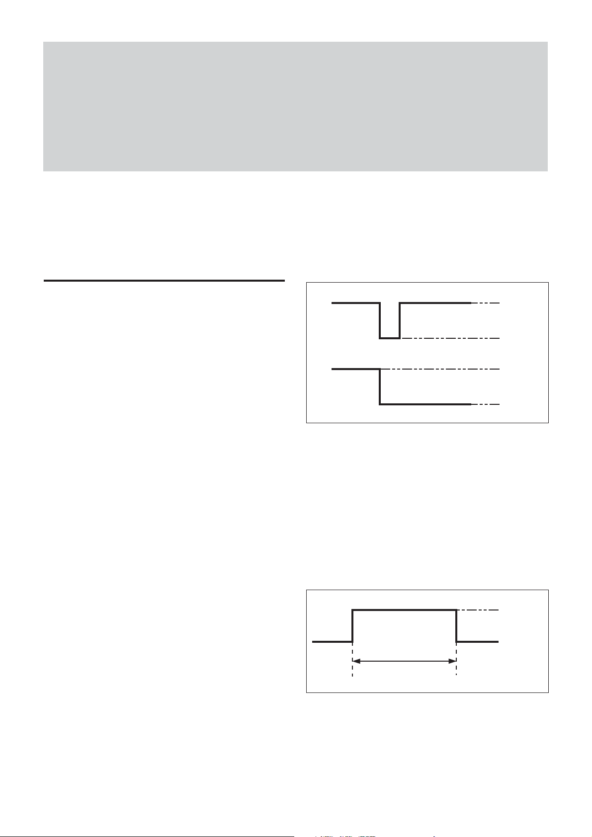
External HD/VD Output Specifications
HD
VD 4.0V
• The amplitude level is the typical value when
terminated with 10 kΩ. External HD and VD can be
output when you set the HD/VD signal input/output
switch of the Mode setting DIP switches to INT
(down position).
• The voltage and pulse width used are as measured at
pin 6 (HD) and pin 7 (VD) of the 12-pin multiconnector on the rear panel.
4.0V
0 – 0.6V
0 – 0.6V
WEN Output Specifications
4.0V
0 – 0.6V
990 H (Binning OFF)
495 H (Binning ON)
• The amplitude level is the typical value when
terminated with 10 kΩ. The pulse width is undefined
during partial scan mode, but WEN rising edge is
always synchronized with internal VD at the start of
image output.
10
Page 11
• The voltage and pulse width used are as measured at
pin 10 of the 12-pin multi-connector on the rear
panel.
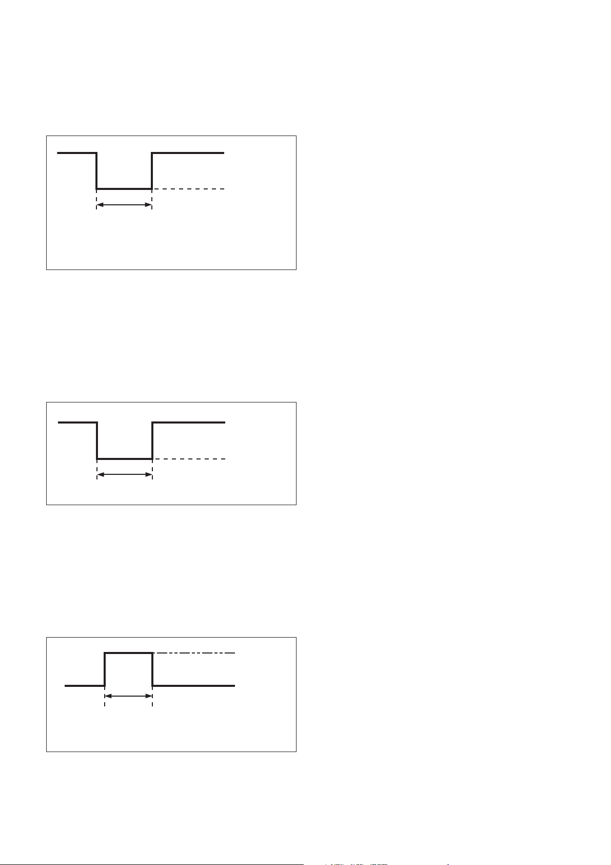
VD Input Specifications
2.5 – 5.0 Vp-p
0 – 0.6V
7 H – 33 H
• Input impedance: 75 Ω or 10 kΩ or more.
• Input amplitude 2.5 to 5.0 Vp-p (for both 75 Ω
termination ON and OFF).
• The voltage and pulse width used are as measured at
pin 7 of the 12-pin multi-connector on the rear panel.
Mode Settings
HD Input Specifications
2.5 – 5.0Vp-p
0 – 0.6V
2.0µs – 5.0µs
• Input impedance: 75 Ω or 10 kΩ or more.
• Input amplitude 2.5 to 5.0 Vp-p (for both 75 Ω
termination ON and OFF)
• The voltage and pulse width used are as measured at
pin 6 of the 12-pin multi-connector on the rear panel.
Trigger Pulse Specifications
2.5 – 5.0V
0 – 0.6V
2µs – 1/4s
• Input impedance: 10 kΩ or more.
• The voltage and pulse width used are measured at pin
11 of the 12-pin multi-connector on the rear panel.
11
Page 12
Mode System Diagram
Trigger Input
HD/VD
Sync System
Mode
Shutter
Function
Vertical
Binning
Mode Settings
Vertical
Partial Scan
No trigger input
Trigger input
Internal
synchronization
External
synchronization
Internal
synchronization
External
synchronization
Normal (INT)
Normal (EXT)
Restart/Reset Not operable
Mode 1
(Trigger non reset)
Mode 2
(Trigger reset)
Mode 1
(Trigger non reset)
Normal Shutter
Normal Shutter
Trigger shutter
Trigger shutter
Trigger shutter
Operable
Operable
Operable
Operable
Operable
Operable
(Internal HD/VD)
Operable
(External HD/VD)
Operable
(External HD/VD)
Operable
(Internal HD/VD)
Operable
(Internal HD/VD)
Operable
(External HD/VD)
12
Page 13
Mode Setting DIP Switches
You can set the mode using the DIP switches located
on the rear of the camera.
Rear panel DIP switches
Mode Settings
Switches 1 to 4: Selecting the shutter
speed * (page 16)
Switches 5 and 0: Select the partial scan
mode * (page 20)
Switches 6 to 8: Selecting the trigger
shutter mode (page 22)
Switch 0: Selecting the binning mode
(OFF/ON) (page 14)
* The normal shutter cannot be used in partial scan mode. To control the
exposure time in partial scan mode, set the mode to restart/reset mode or
external trigger shutter mode (controlling the trigger pulse width).
13
Page 14
Video Output Modes
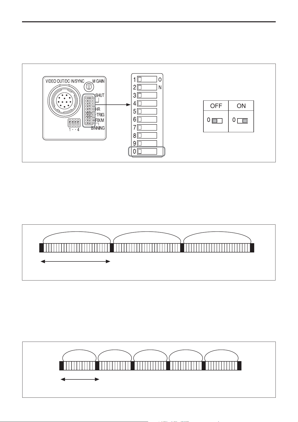
This unit has two video signal output modes. Select the
mode with the binning mode switch (DIP switch 0) on
the rear panel.
Mode Settings
Rear panel
Binning OFF
30 fps mode: Signals for each independent pixel are
output from the VIDEO OUT connector every 1/30 s
(line sequential output).
External synchronization is possible by external HD/
VD
DIP switches
Binning mode
15 fps mode: Signal for each independent pixel are
output from the VIDEO OUT connector every 1/15 s
(line sequential output).
Frame image Frame image Frame image
1/30 s (990 H)
1/15 s (990 H)
Binning ON
30 fps mode: Mixed signals for vertically adjacent
pixels are output from the VIDEO OUT connector
every 1/54.1 s.
External synchronization is possible by external HD/
VD.
Binning image Binning image Binning image Binning image Binning image
15 fps mode: Mixed signals for vertically adjacent
pixels are output from the VIDEO OUT connector
every 1/30 s.
1/54.1 s (495 H)
1/30 s (495 H)
14
Page 15
About the Electronic Shutter
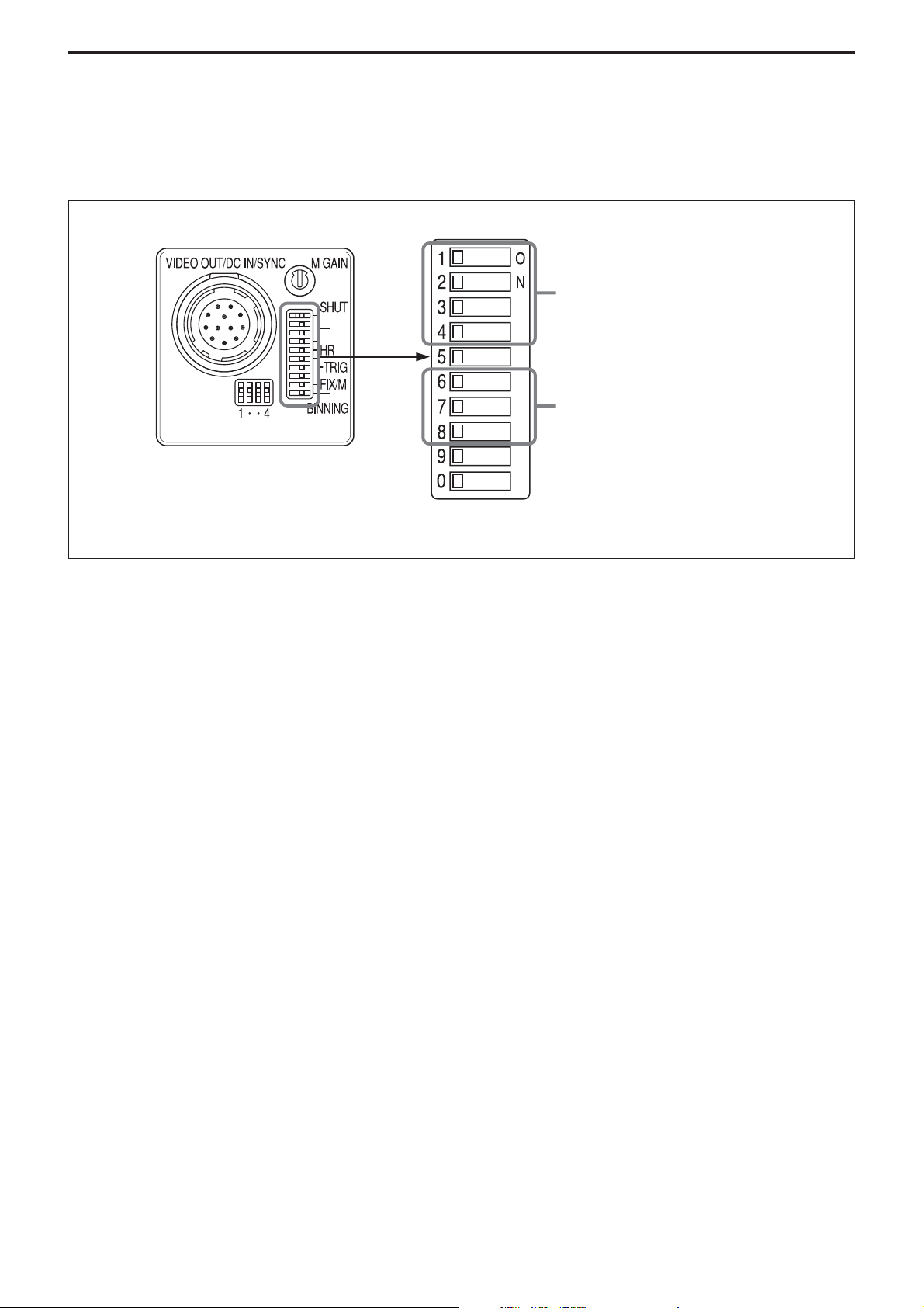
There are two shutter types: normal shutter and
external trigger shutter. Select them with the DIP
switches on the rear panel.
Mode Settings
Rear panel
For detailed information on the normal shutter, see “Normal
Shutter” on page 16, and for detailed information on the
trigger shutter, see “External Trigger Shutter” on page 22.
DIP switches
Switches 1 to 4: Selecting the shutter
speed
Switches 6 to 8: Selecting the trigger
shutter mode
15
Page 16
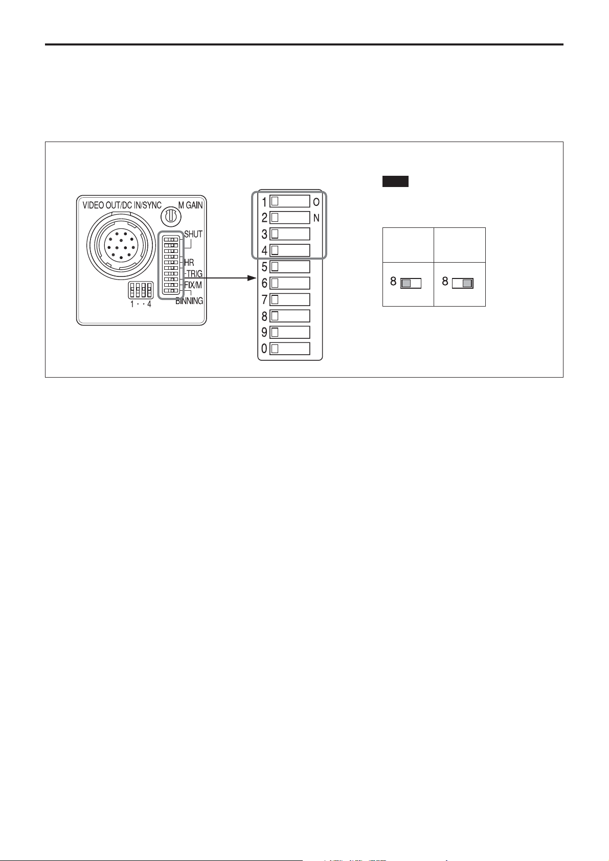
Normal Shutter
This mode provides continuous video output with the
electronic shutter selected by switches to capture a
high-speed moving object clearly.
Mode Settings
Rear panel
DIP switches
Note
Be sure to set the switch 8 to OFF (left
side) as shown below when using the
normal shutter.
Normal
shutter
* “Other modes” refers to restart/reset
mode and external trigger shutter
mode.
Other
mode*
16
Page 17
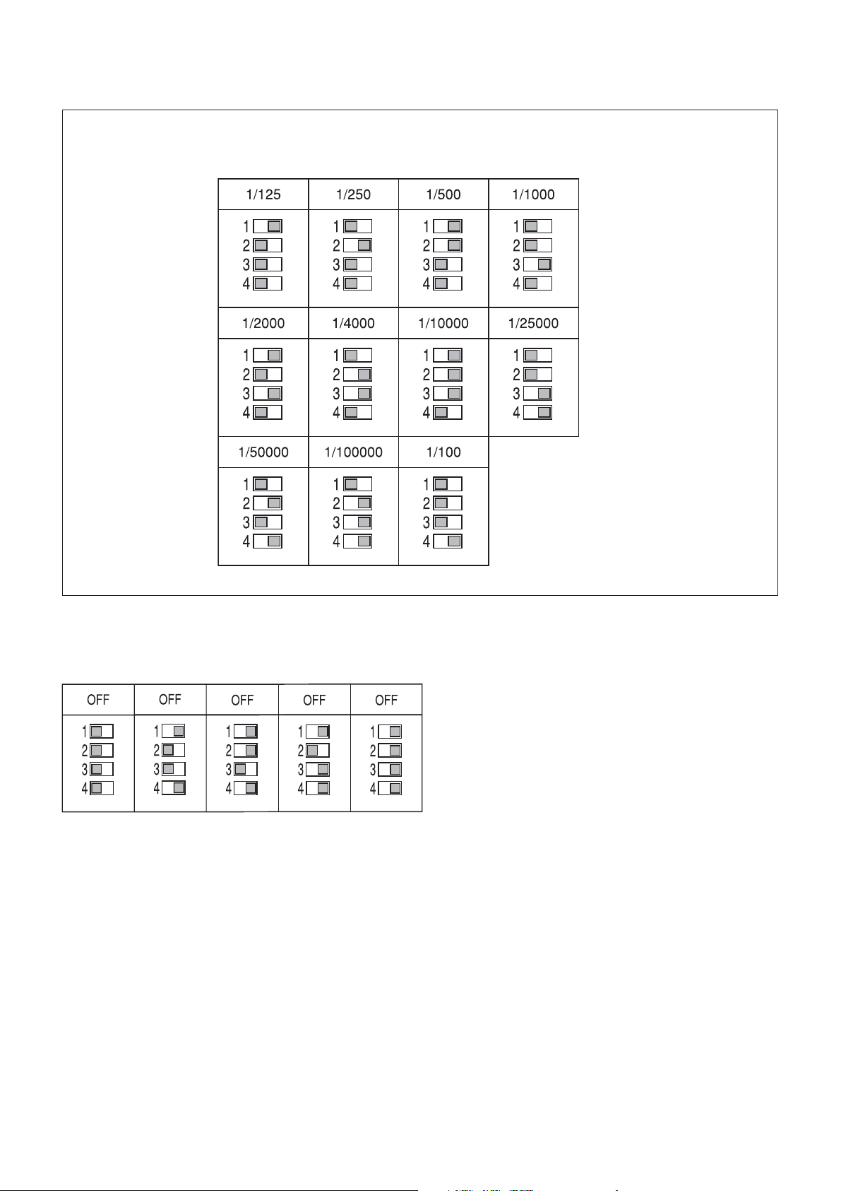
30 fps Mode
Mode Settings
Normal shutter speed settings
The shutter will be OFF when the dip switches are set
to each combination which mentioned below.
(Unit: seconds)
17
Page 18
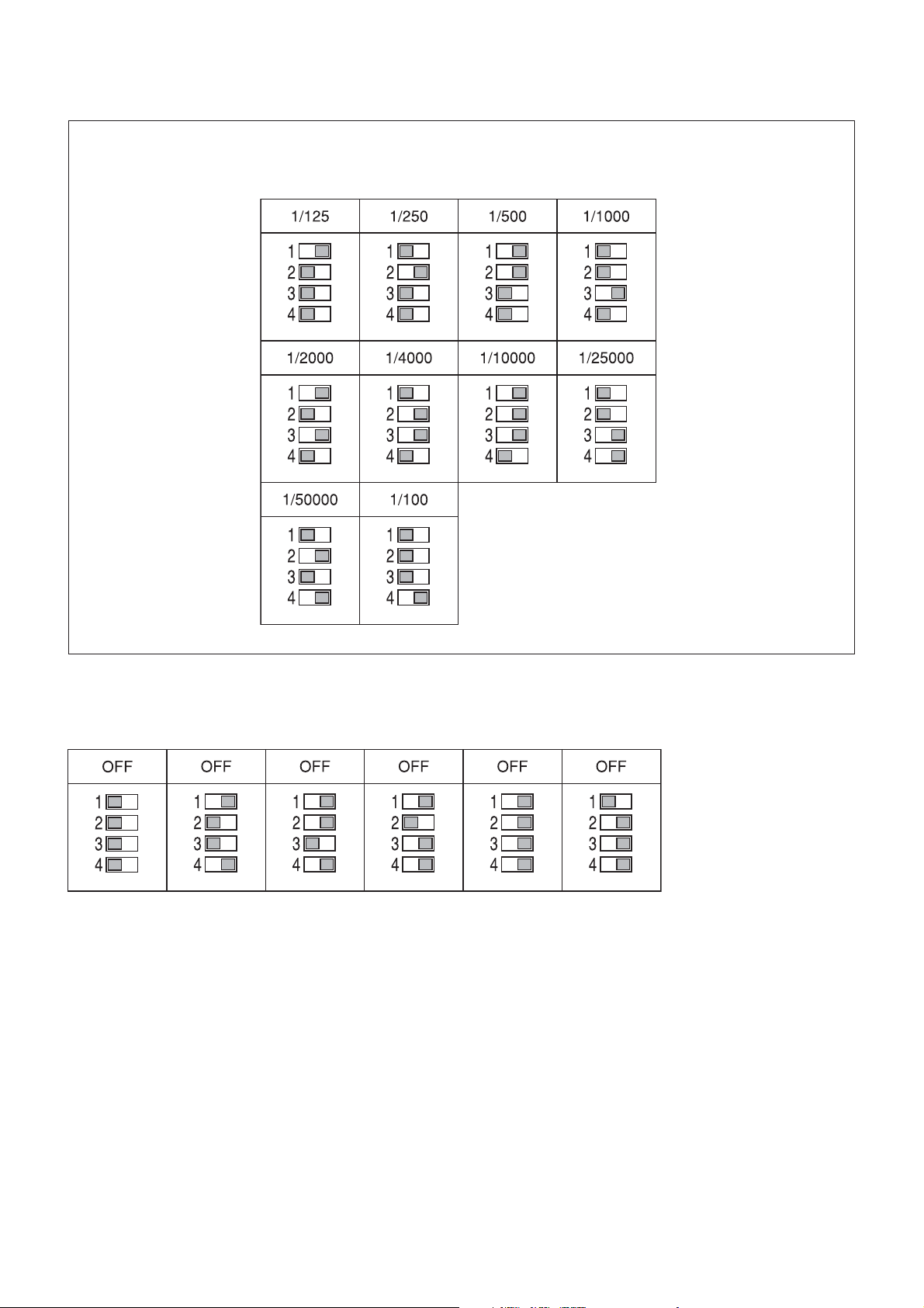
15 fps Mode
Mode Settings
Normal shutter speed settings
The shutter will be OFF when the dip switches are set
to each combination which mentioned below.
(Unit: seconds)
18
Page 19
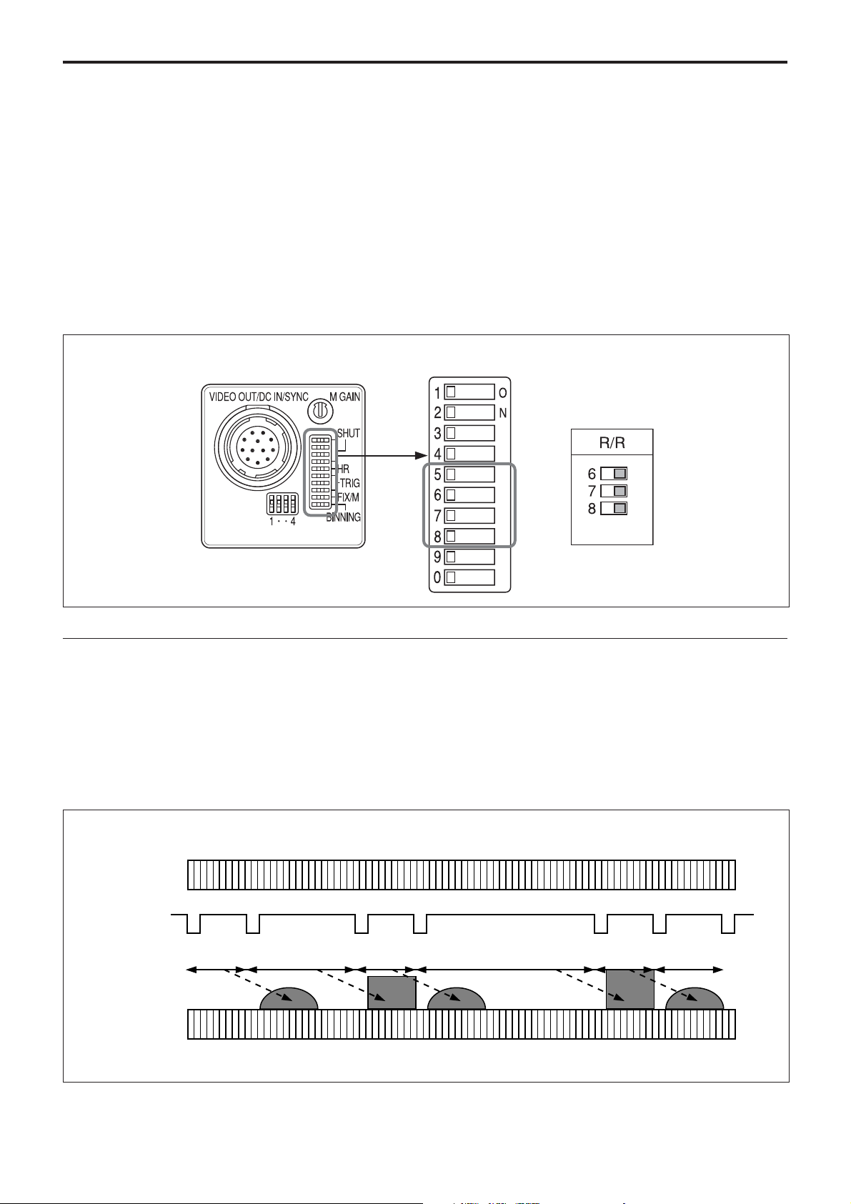
Restart/Reset
Setting Restart/Reset Mode
The information on one screen can be extracted at
any time by externally inputting restart/reset signals
(HD/VD). To enter this mode, set the trigger shutter
switches (6 to 8) on the rear panel of the camera as
shown in the figure below.
To use restart/reset mode and partial scan mode
simultaneously, set the partial scan mode switch (5)
to ON (right side).
Mode Settings
Rear panel
Long exposure
The Restart/Reset function extends the CCD
accumulation time, resulting in highly sensitive
image capture. This function is effective when you
cannot gain satisfactory sensitivity under normal
operating conditions, or when you want to observe
the trail of a moving object. Extend the VD interval
(T) between external VD pulses.
DIP switches
Example of input timing chart
EXT-HD
EXT-VD
Charge
accumulation
on CCD
VIDEO OUT
T
19
Page 20
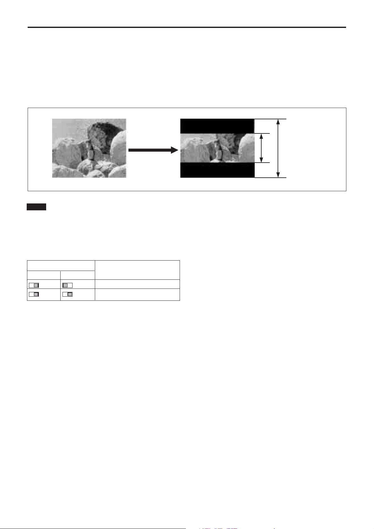
Partial Scan Mode
Mode Settings
You can increase the frame rate by setting the upper
high-speed transfer (FPS) and the lower high-speed
transfer (RPS) via the RS-232C interface. When the
RS-232C ON/OFF switch is set to OFF, you can set
Notes
• In trigger shutter mode, video out signals are output
about 1 H later than the external VD.
• In partial scan mode, image output and the WEN
rising edge are always synchronized, but the WEN
width becomes undefined.
the 1/2 partial scan mode or 1/4 partial scan mode by a
combination of switch 5 and switch 10 located on the
rear panel.
The image is centered as shown below.
X lines 960 lines
Dip switch setting Operating mode
Switch 5 Switch 10
1/2 V partial scan
1/4 V partial scan
20
Page 21
Mode Settings
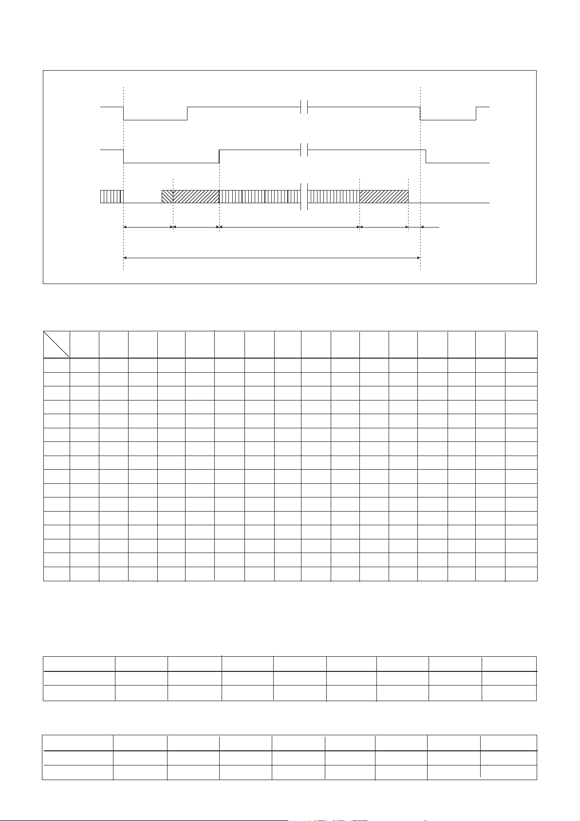
Timing Chart for Partial Scan Mode (Internal Synchronization)
VD
VBLK
Video Out
BLKG
interval
Upper
high-speed
transfer
Effective lines
VD interval
Lower highspeed transfer
Setting of FPS and RPS, the number of output lines
RPS
0123456789ABCDEF
FPS
0 960 900 840 780 720 660 600 540 480 420 360 300 240 180 120 60
1 900 840 780 720 660 600 540 480 420 360 300 240 180 120 60 —
2 840 780 720 660 600 540 480 420 360 300 240 180 120 60 — —
3 780 720 660 600 540 480 420 360 300 240 180 120 60 — — —
4 720 660 600 540 480 420 360 300 240 180 120 60 ————
5 660 600 540 480 420 360 300 240 180 120 60 —————
6 600 540 480 420 360 300 240 180 120 60 ——————
7 540 480 420 360 300 240 180 120 60 ———————
8 480 420 360 300 240 180 120 60 ————————
9 420 360 300 240 180 120 60 —————————
A 360 300 240 180 120 60 ——————————
B 300 240 180 120 60 ———————————
C 240 180 120 60 ————————————
D 180 120 60 —————————————
E 120 60 ——————————————
FPS: Upper high-speed transfer.
RPS: Lower high-speed transfer
Number of lines and frame rate
Number of lines 60 120 180 240 300 360 420 480
30 fps 204.83 148.5 116.47 95.81 81.37 70.72 62.53 56.04
15 fps 102.42 74.25 58.24 47.90 40.69 35.36 31.26 28.02
Number of lines and frame rate
Number of lines 540 600 660 720 780 840 900 960
30 fps 50.77 46.41 42.73 39.60 36.9 34.54 32.46 30.62
15 fps 25.39 23.20 21.37 19.80 18.45 17.27 16.23 15.31
21
Page 22
External Trigger Shutter
Mode Settings
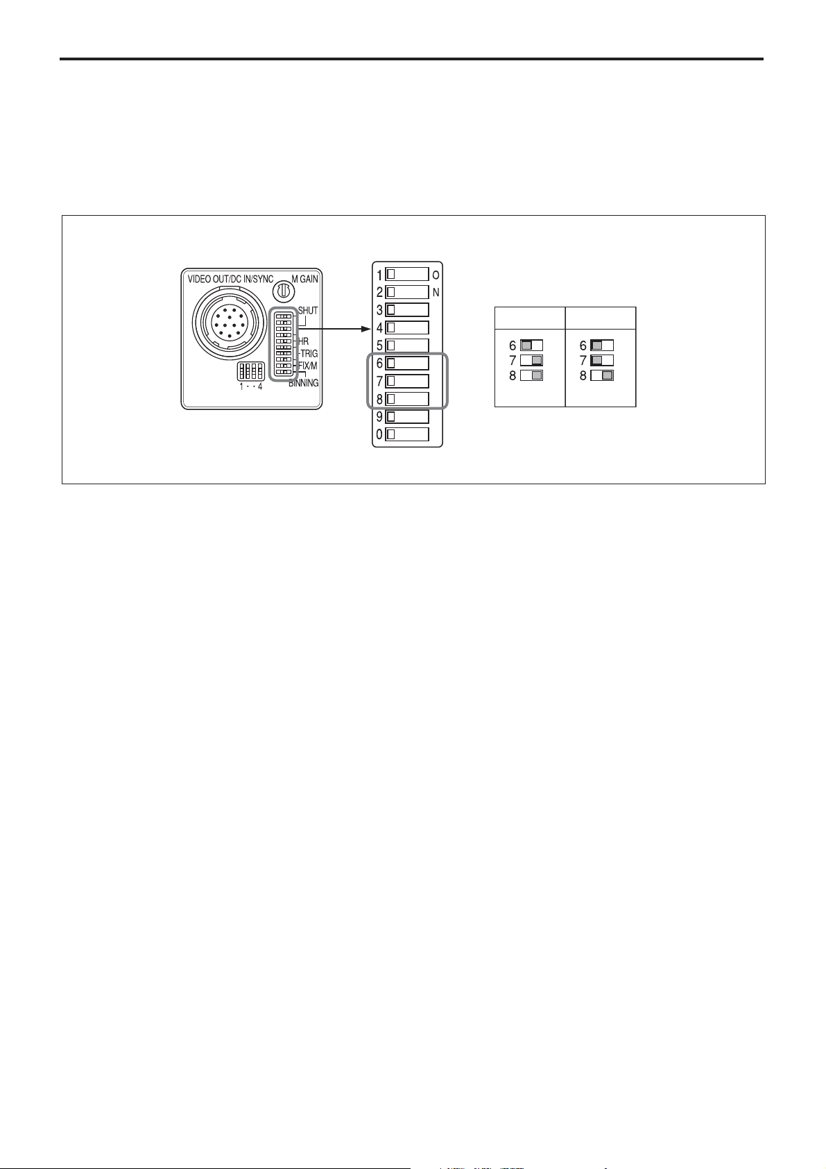
Inputting an external trigger pulse enables the camera
to capture fast-moving objects clearly with precise
timing.
Set DIP switches 6, 7, and 8 on the rear panel to Mode
1 or Mode 2.
Rear panel
DIP switches
When you set the trigger pulse width to 1/4 of a
second or more, the output signal changes to the
normal VIDEO signal.
Mode 1 Mode 2
There are two modes for the timing in which video
signals are obtained.
• Mode 1 (Non-reset mode)
In this mode, a video signal synchronized with a VD
signal is output after a trigger pulse is input.
– The video signal is synchronized with the external
VD signal when an external HD*/VD signal is
input.
– The video signal is synchronized with an internal
VD signal when no external HD*/VD signal is
input.
* External or internal synchronization is selected
automatically depending on the presence or absence
of external HD input.
• Mode 2 (Reset mode)
In this mode, an internal VD is reset, then a video
signal is output a certain period of time after trigger
pulse input.
22
Page 23
Mode Settings
Setting the External Trigger Shutter
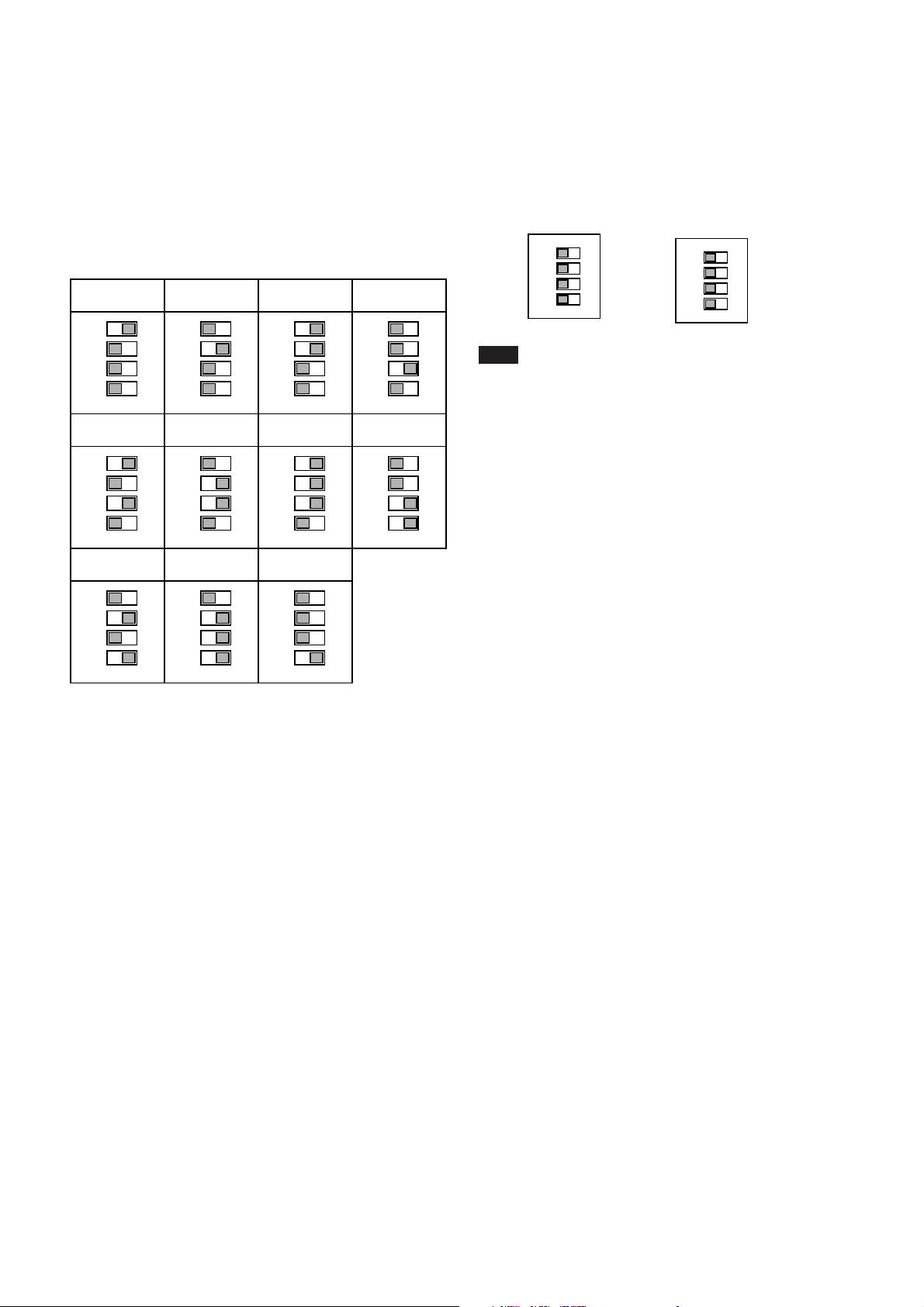
There are two ways to set the shutter speed.
Using the DIP switches on the rear panel
For shutter speeds, see the following table.
Mode 1 (Non-reset mode)/Mode 2 (Reset mode)
1/125
1
2
3
4
1/2000 1/4000 1/10000 1/25000
1
2
3
4
1/250 1/500 1/1000
1
2
3
4
1
2
3
4
1
2
3
4
1
2
3
4
Using trigger pulse width
Set all DIP switches (1 to 4 on the rear panel) to OFF.
You can obtain an arbitrary shutter speed by setting
µ
the trigger pulse width to the range of 2
sec to
250 msec.
Mode 1 (Non-reset mode) Mode 2 (Reset mode)
1
2
3
4
1
2
3
4
1
2
3
4
Note
An incorrect video signal will be output if you input a
new trigger pulse before the video signal output for the
previous trigger pulse is output completely.
1
2
3
4
1/50000 1/100000
1
2
3
4
1
2
3
4
1/100
1
2
3
4
(Unit: Second)
23
Page 24
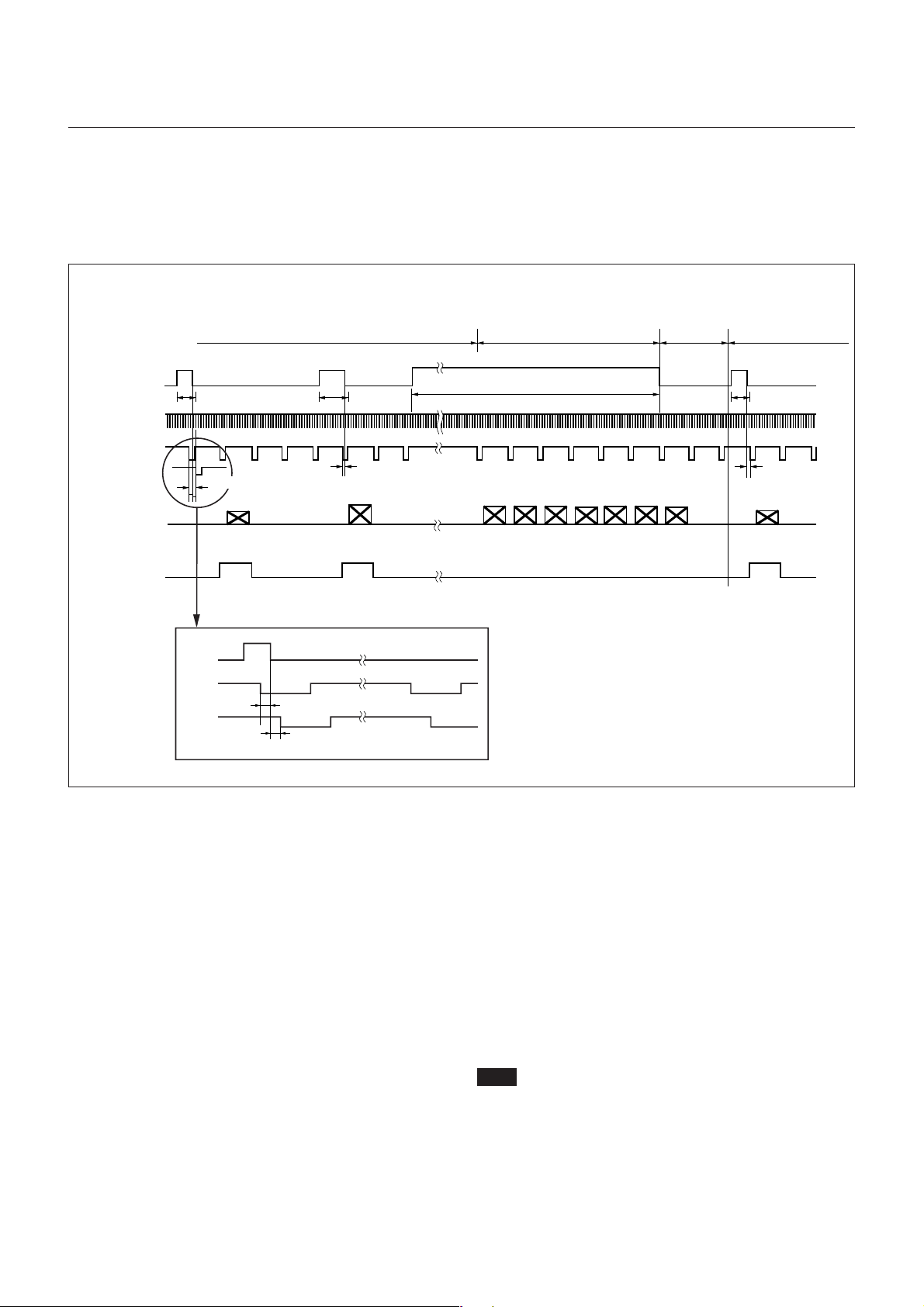
Timing Chart
When set to Mode 1 (Non-reset mode)
Setting the shutter speed using trigger pulse width
◆ HD/VD input
• Continuous VD input
External trigger shutter operation
Normal operation*
Mode transition state
External input
3
inhibition area
(50 ms)
Mode Settings
External trigger
shutter operation
1
Trigger*
External HD*
External VD*
(Continuous
VD)
EXT-VD
Video out
WEN
1
1
1
Shutter speed (Te)*
T: T=under 10 µs*
1
990 H (Binning OFF)
495 H (Binning ON)
TRG
EXT-VD
EXT-VD
2
4
32 µs
10 µs
2
Shutter speed
2
(Te)
*
T: T=under 10 µs*
2
Trigger pulse width*
4
3
3
Shutter speed (Te)
10 µs or more
3
2
*
*1 This is an external input signal. Make sure to input
both HD and VD signals.
*2 Shutter speed (Te)
µ
Te = Trigger pulse width + 5
sec
(The effective trigger pulse width for the external
µ
trigger shutter operation is between 2
s and 1/4 s.)
*3 Normal operation is resumed when the trigger
pulse width is 1/3 s or more. The trigger falling
edge restores external trigger shutter operation. At
this time, the 50 ms after the falling edge of the
trigger pulse is an external trigger input inhibition
area. There is no guarantee of operation for any
trigger input in this period.
*4 If there is a falling edge on the external VD within
µ
a period of +10
s from the falling trigger edge (1
and 2 in the figure), it is not defined whether the
image is output for the external VD falling edge or
the image is output for the next external VD falling
edge. (1 in the figure shows that the image is
output for the next external VD. 2 shows the
image for the external VD.) In this case, see WEN
since output of the image and WEN make up a
pair. In any other case, the image is output for the
external VD falling edge after the trigger falling
edge (3 in the figure).
Note
An image is not output correctly when the next trigger is
input before the image for the previous trigger has been
output.
24
Page 25
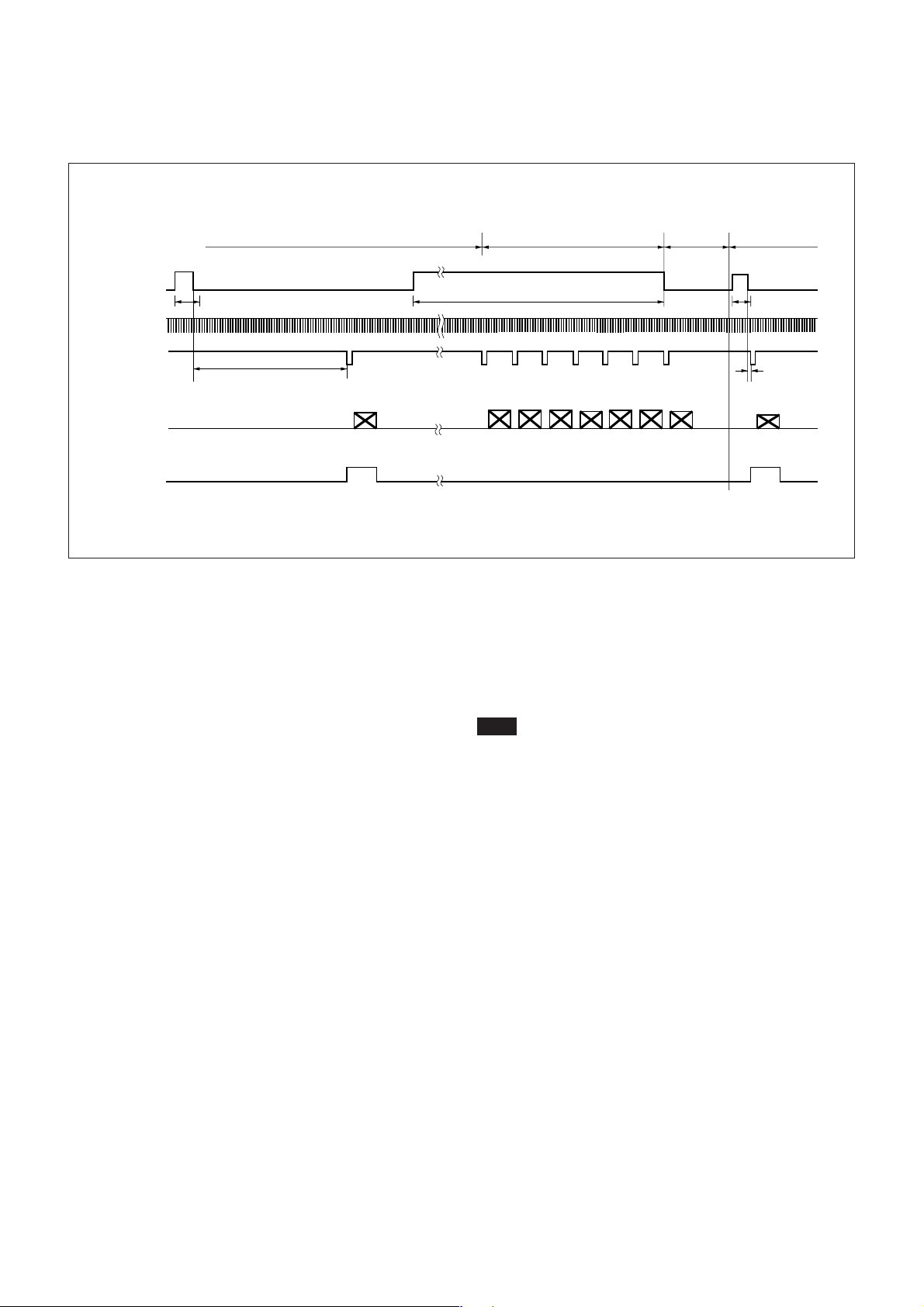
Setting the shutter speed using trigger pulse width
◆ HD/VD input
• Continuous HD input/Single VD input
External trigger shutter operation
Normal operation*
Mode transition state
External input
3
inhibition area
(50 ms)
Mode Settings
External trigger
shutter operation
1
Trigger*
External HD*
External VD*
(Single VD)
Video out
WEN
1
Shutter speed (Te)*
1
1
T: T=10 µs to 35 ms*
2
4
1
990 H (Binning OFF)
495H (Binning ON)
*1 This is an external input signal. Make sure to input
both HD and VD signals in this case.
*2 Shutter speed (Te)
µ
Te = Trigger pulse width + 5
sec
(The effective trigger pulse width for the external
µ
trigger shutter operation is between 2
s and 1/4 s.)
*3 Normal operation is resumed when the trigger
pulse width is 1/3 s or more. The trigger falling
edge restores external trigger shutter operation. At
this time, the 50 ms after the falling edge of the
trigger pulse is an external trigger input inhibition
area. There is no guarantee of operation for any
trigger input in this period.
2
Trigger pulse width*
*4 Input the external VD within the period of 10
3
Shutter speed
2
(Te)*
Min. 10 µs
2
µ
s to
35 ms after the trigger falling edge (1 and 2 in
the figure). There is no guarantee of operation for
any other input. If an invalid signal is input, the
input is changed to a valid signal and, after several
V signals, normal operation resumes.
Note
Make sure that the trigger signal and the VD signal
make up a pair.
An image is not output correctly when the next trigger
is input before the image for the previous trigger has
been output.
25
Page 26
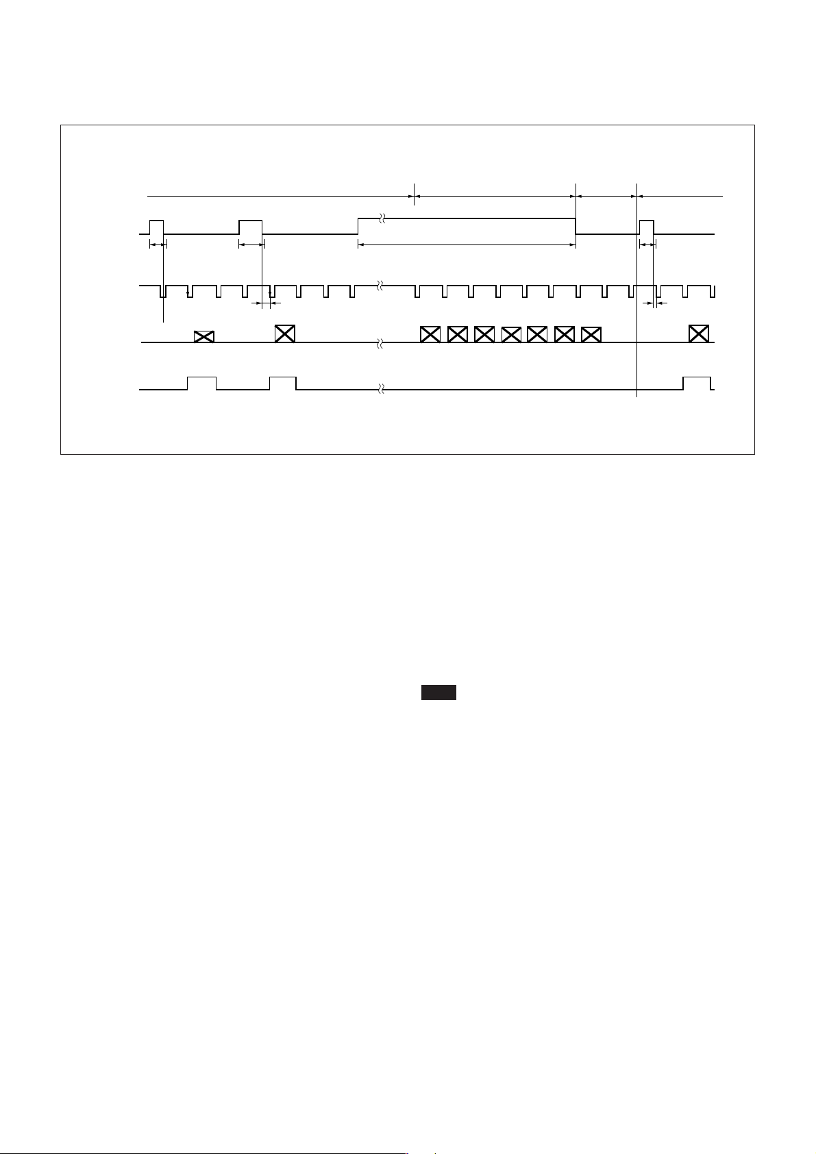
Setting the shutter speed using trigger pulse width
◆ No HD/VD input (Internal synchronization)
External trigger shutter operation
Normal operation*
Mode transition state
External input
inhibition area
3
(50 ms)
Mode Settings
External trigger
shutter operation
1
Trigger*
Internal VD*
Video out
WEN
1
Shutter
speed
2
(Te)*
4
1
990 H (Binning OFF)
495 H (Binning ON)
2
Shutter
speed
2
(Te)*
T: T=10 µs or more*
2
5
*1 This is an external input signal.
*2 Shutter speed (Te)
µ
Te = Trigger pulse width + 5
s
(The effective trigger pulse width for the external
µ
trigger shutter operation is between 2
s and 1/4 s.)
*3 Normal operation is resumed when the trigger
pulse width is 1/3 s or more. The trigger falling
edge restores external trigger shutter operation. At
this time, the 50 ms after the falling edge of the
trigger pulse is an external trigger input inhibition
area. There is no guarantee of operation for any
trigger input in this period.
*4 The internal VD signals are output as long as there is
no external input and the HD/VD signal input/output
switch of the mode setting DIP switch on the rear
panel is set to set to INT (down position).
3
Trigger pulse width*
3
Shutter speed
2
(Te)*
T: T=under 10 µs*
3
5
*5 In external trigger operation, the image is output
for the internal VD falling edge after the trigger
falling edge (1 and 2 in the figure). If the period
from the trigger falling edge to the internal VD
µ
falling edge (T in the figure) is under 10
s, it is
not defined whether the image is output for the
internal VD falling edge or the image is output for
the next internal VD falling edge. (3 in the figure
shows that the image is output for the next internal
VD). In this case, see WEN since the image and
WEN make up a pair.
Note
An image is not output correctly when the next trigger
is input before the image for the previous trigger has
been output.
26
Page 27
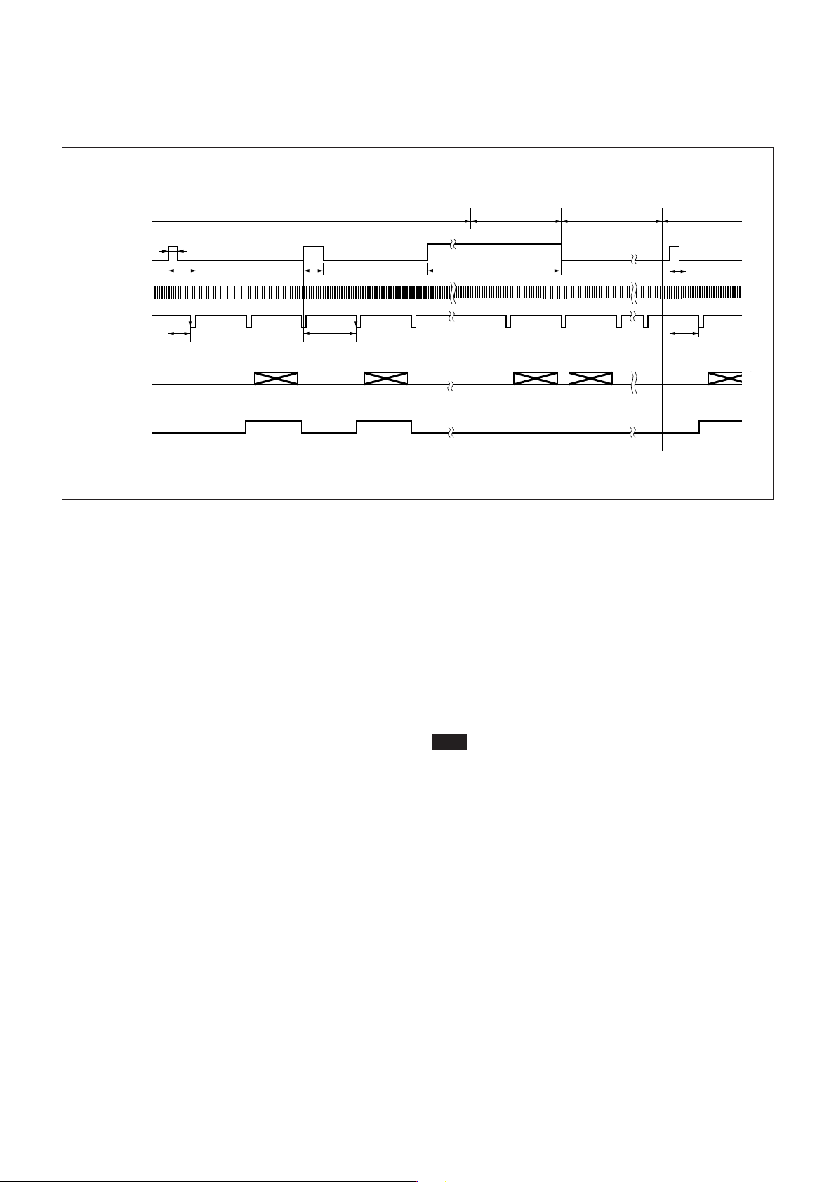
Setting the shutter speed using DIP switches
◆ HD/VD input
• Continuous VD input
External trigger shutter operation
Normal
operation*
Mode transition state
External input
3
inhibition area
(50 ms)
Mode Settings
External trigger
shutter operation
Trigger*
External HD*
External VD*
(Continuous
VD)
Video out
WEN
1
1
2 µs to 250 ms
1
1
Shutter speed (Te)*
T: T=under 10 ms*
4
990 H (Binning OFF)
495H (Binning ON)
2
2
Shutter speed (Te)*
T: T=10 ms or more*
1
2
*1 This is an external input signal. Make sure to input
both HD and VD signals.
*2 The shutter speed (Te) is determined by the setting
of DIP switches.
For details, see page 23.
*3 Normal operation is resumed when the trigger
pulse width is 1/3 s or more. The trigger falling
edge restores external trigger shutter operation. At
this time, the 50 ms after the falling edge of the
trigger pulse is an external trigger input inhibition
area. There is no guarantee of operation for any
trigger input in this period.
3
Trigger pulse width*
2
4
3
T: T=10 ms or
more*
*4 An image is output when an external VD signal
falls 10 ms or more after a trigger pulse rises (2
and 3 in the figure). If the period from the trigger
rising edge to the external VD falling edge (T in
the figure) is under 10 ms, it is not defined whether
the image is output for the external VD falling
edge or the image is output for the next external
VD falling edge. (1 in the figure shows that the
image is output for the next external VD). In this
case, see WEN since the image and WEN make up
a pair.
Note
An image is not output correctly when the next trigger
is input before the image for the previous trigger has
been output.
Shutter speed
2
(Te)*
4
3
27
Page 28
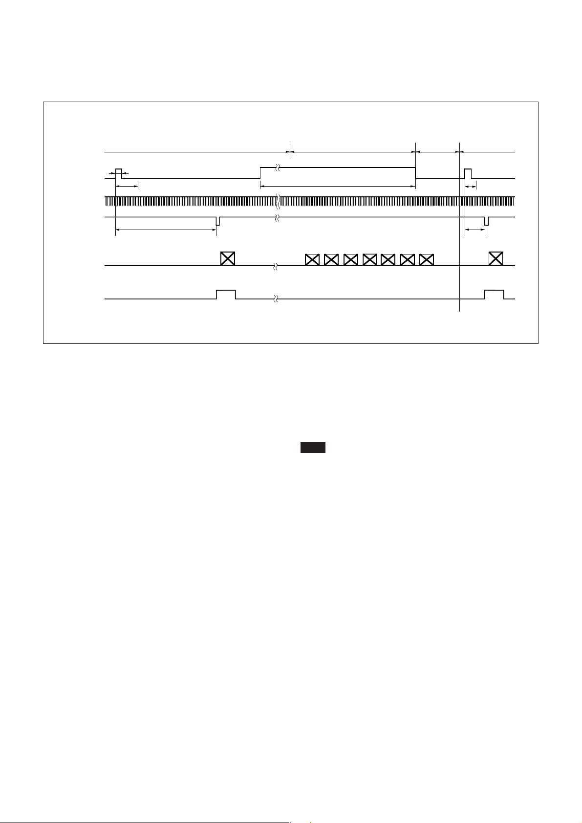
Setting the shutter speed using DIP switches
◆ HD/VD input
• Continuous HD input/Single VD input
External trigger shutter operation Normal operation*
Mode transition state
External input
3
inhibition area
(50 ms)
Mode Settings
External trigger
shutter operation
1
Trigger*
External HD*
External VD*
(Single VD)
Video out
WEN
1
2 µs to 250 ms
Shutter speed (Te)*
1
1
T: T=10 ms to 45 ms*
2
4
1
990 H (Binning OFF)
495 H (Binning ON)
*1 This is an external input signal. Make sure to input
both HD and VD signals in this case. Input the
signal so that the VD phase aligns with the HD
falling edge.
*2 The shutter speed (Te) is determined by the setting
of the DIP switches.
For details, see page 23.
*3 Normal operation is resumed when the trigger
pulse width is 1/3 s or more. The trigger falling
edge restores external trigger shutter operation. At
this time, the 50 ms after the falling edge of the
trigger pulse is an external trigger input inhibition
area. There is no guarantee of operation for any
trigger input in this period.
2
Trigger pulse width*
*4 Input the external VD within the period of 10
3
Shutter speed
2
(Te)*
Min.10 ms
2
ms to
45 ms after the trigger rising edge (1 and 2 in
the figure). There is no guarantee of operation for
any other input. If an invalid signal is input, the
input is changed to a valid signal, and after several
V signals, normal operation resumes.
Note
Make sure that the trigger signal and the VD signal
make up a pair.
An image is not output correctly when the next trigger
is input before the image for the previous trigger has
been output.
28
Page 29
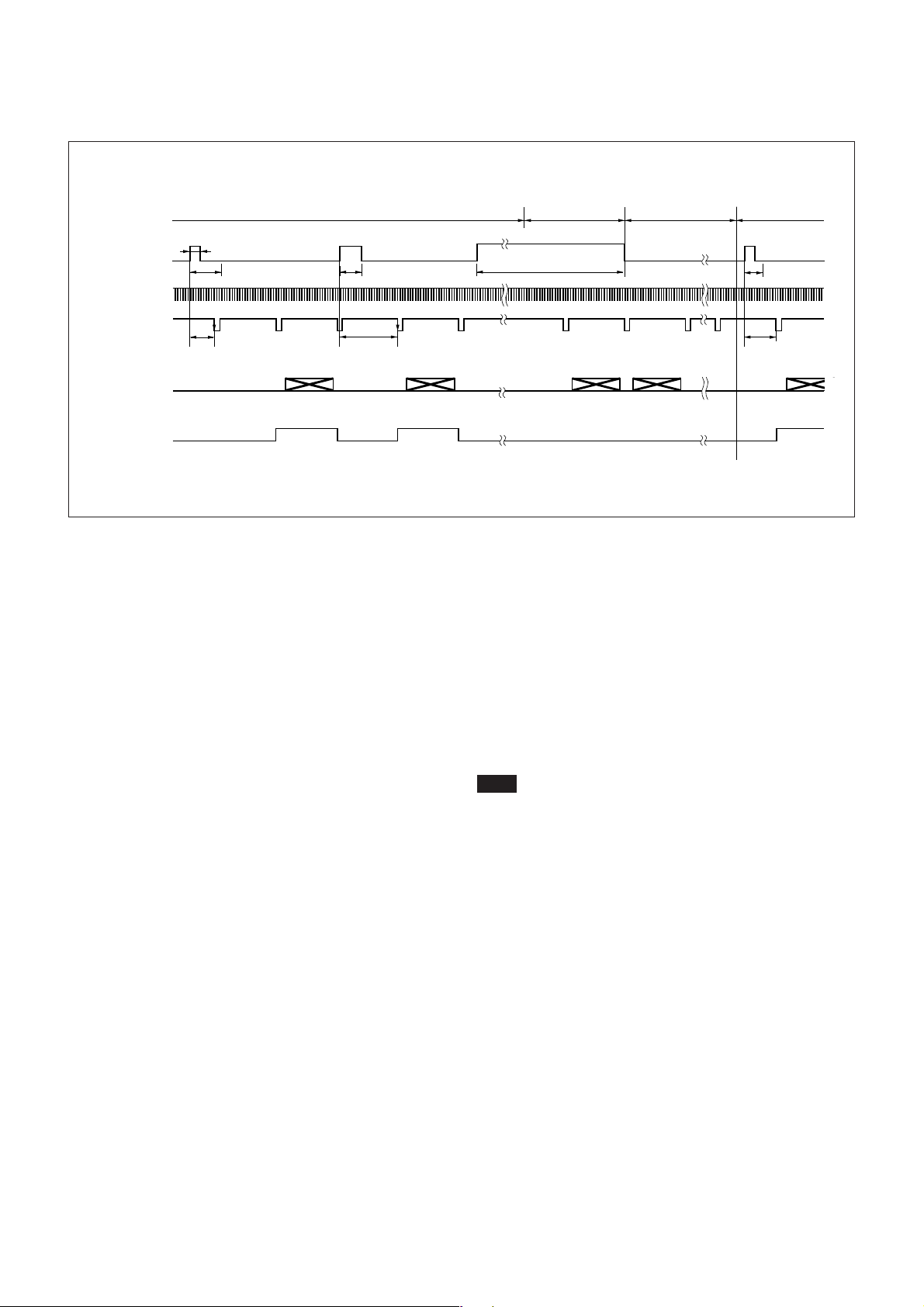
Setting the shutter speed using DIP switches
◆ No HD/VD input (Internal synchronization)
External trigger shutter operation
Normal
operation*
Mode transition state
External input
3
inhibition area
(50 ms)
Mode Settings
External trigger
shutter operation
Trigger*
Internal VD*
Video out*
WEN
1
1
4
T: T=under 10 ms*
6
2 µs to 250 ms
Shutter speed (Te)*
5
990 H (Binning OFF)
495 H (Binning ON)
2
2
Shutter speed (Te)*
T: T=10 ms or more*
1
2
*1 This is an external input signal.
*2 The shutter speed (Te) is determined by the setting
of the DIP switches.
For details, see page 23.
*3 Normal operation is resumed when the trigger
pulse width is 1/3 s or more. The trigger falling
edge restores external trigger shutter operation. At
this time, the 50 ms after the falling edge of the
trigger pulse is an external trigger input inhibition
area. There is no guarantee of operation for any
trigger input in this period.
*4 The internal VD signals are output as long as there
is no external input and the HD/VD signal
input/output switch of the mode setting DIP switch
on the rear panel is set to the down position (INT).
3
Trigger pulse width*
2
5
3
Shutter speed
(Te)*
T: T=10 ms or
5
more*
*5 An image is output when an internal VD signal
falls 10 ms or more after a trigger pulse rises (2
and 3 in the figure). If the period from the
trigger rising edge to the internal VD falling edge
(T in the figure) is under 10 ms, it is not defined
whether the image is output for the external VD
falling edge or the image is output for the next
external VD falling edge. (1 in the figure shows
that the image is output for the next internal VD).
In this case, see WEN since the image and WEN
make up a pair.
Note
An image is not output correctly when the next
trigger is input before the image for the previous
trigger has been output.
2
3
29
Page 30
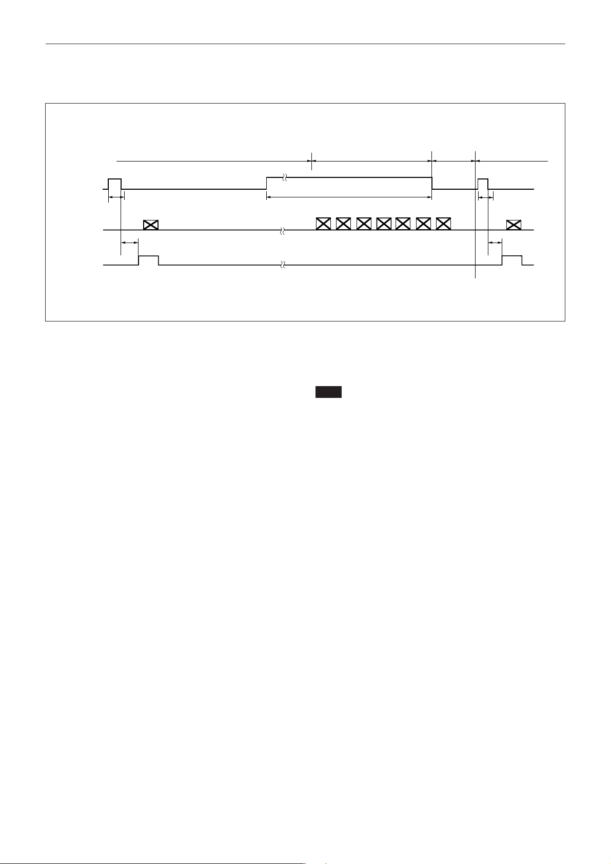
When set to Mode 2 (Reset mode)
Setting the shutter speed using trigger pulse width
External trigger shutter operation
Normal operation*
Mode transition state
External input
3
inhibition area
(50 ms)
Mode Settings
External trigger
shutter operation
Trigger*
Video out
WEN
1
1 H to 2 H*
Shutter speed (Te)*
4
990 H (Binning OFF)
495 H (Binning ON)
2
*1 This is an external input signal.
*2 Shutter speed (Te)
µ
Te = Trigger pulse width + 5
sec
(The effective trigger pulse width for the external
µ
trigger shutter operation is between 2
s and 1/4 s.)
*3 Normal operation is resumed when the trigger
pulse width is 1/3 s or more. The trigger falling
edge restores external trigger shutter operation. At
this time, the 50 ms after the falling edge of the
trigger pulse is an external trigger input inhibition
area. There is no guarantee of operation for any
trigger input in this period.
Trigger pulse width*
3
Shutter speed
2
(Te)*
1 H to 2 H*
*4 The video out is started after 1 H to 2 H from the
trigger falling edge, then the image is output
synchronized with the WEN pulse rising edge.
Note
An image is not output correctly when the next trigger
is input before the image for the previous trigger has
been output.
4
30
Page 31
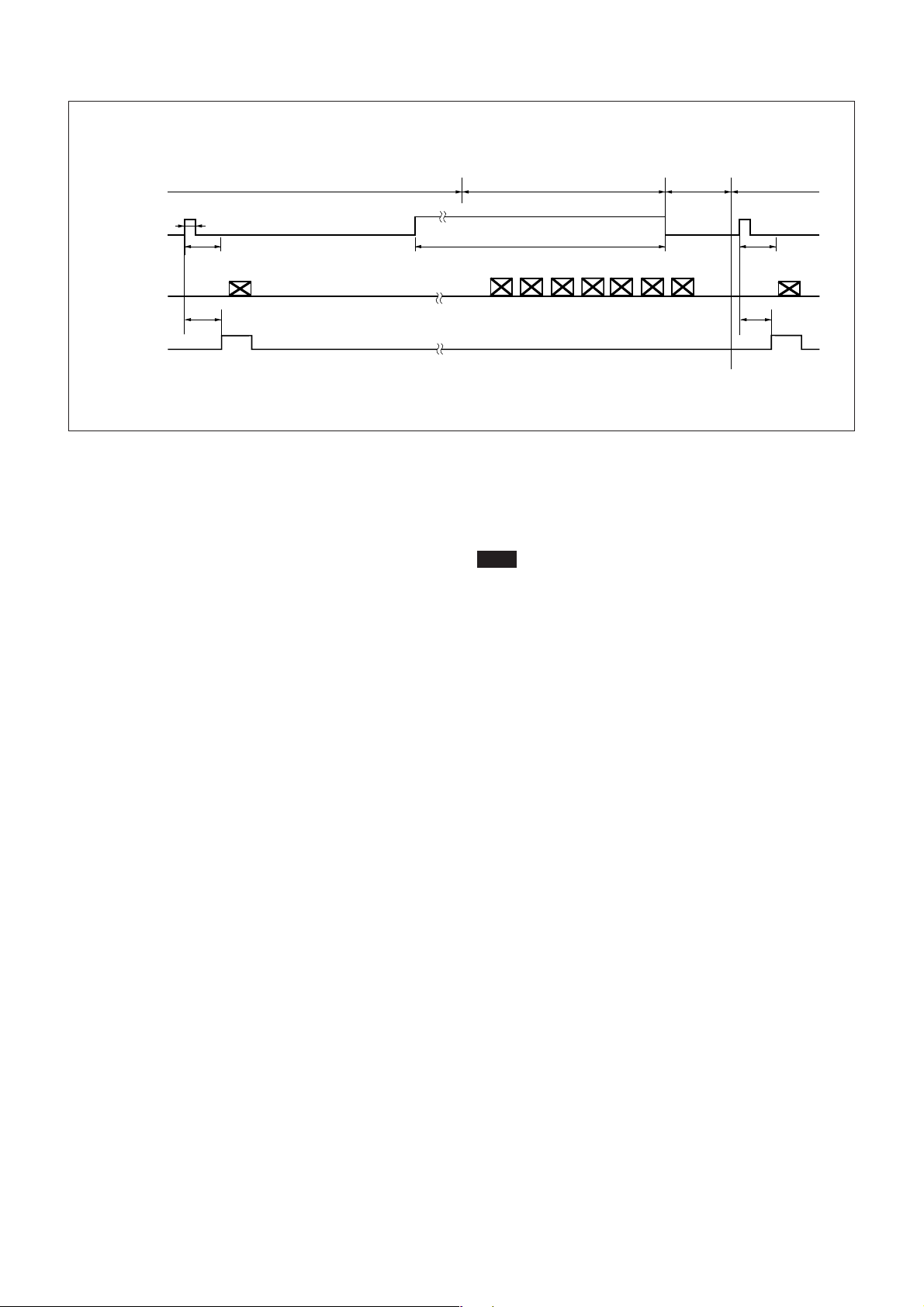
Setting the shutter speed using the DIP switches
External trigger shutter operation
1
Trigger*
Video out
2 µs to 250 ms
Shutter speed (Te)*
2
Normal operation*
Trigger pulse width*
Mode Settings
Mode transition state
External input
3
3
inhibition area
(50 ms)
External trigger
shutter operation
Shutter speed
2
(Te)*
4
WEN
T*
990 H (Binning OFF)
495 H (Binning ON)
*1 This is an external input signal.
*2 The shutter speed (Te) is determined by the setting
of the DIP switches.
For details, see page 17.
*3 Normal operation is resumed when the trigger
pulse width is 1/3 s or more. The trigger falling
edge restores external trigger shutter operation. At
this time, the 50 ms after the falling edge of the
trigger pulse is an external trigger input inhibition
area. There is no guarantee of operation for any
trigger input in this period.
4
T*
*4 The image is output at the shortest timing from the
trigger rising edge according to the DIP switch
setting. The image is output synchronized with the
WEN pulse rising edge.
Note
An image is not output correctly when the next trigger
is input before the image for the previous trigger has
been output.
31
Page 32
Camera Control Command
Camera Control Command
It is recommended that you make a test under the
condition you will operate the camera before using the
camera actually.
Overview
The XC-HR90 (Black and White Video
Camera Module) can be controlled externally using
serial communication.
Serial Communication Specifications
The serial communication system for the camera is an
asynchronous method compliant with the RS-232C
standard. The following table shows the transmission
control specifications.
Command inputs are echoed back.
Baud rate 115200/4800 [bps]
Default setting: 38400[bps]
Data bits 8
Parity None
Stop bit 1
Flow control None
Command Input and Response
When the camera receives commands from the host, it
returns a response after each command is processed.
Input commands are echoed back.
Note
To input multiple commands in sequence, input a
command after the previous command returns its
response.
Command response messages are as follows:
OK : normal
Error : syntax error
Error : status error
■When command execution is completed normally,
“OK[CR]” is returned.
Example:
<Input> PARTIAL 1 <CR>
<Output on screen> OK[CR]
■ If command execution is terminated abnormally,
“Error[CR]” is returned.
■ When no parameter is input for a command
requiring parameters, the current parameters of the
command are returned.
Command Format
To input (send) a command, delimit a command name
and parameters with spaces, and press the Carriage
Return (CR) key.
The following shows the input format and an example:
<Input format> command param1 param2 [CR]
<Input example> PARTIAL 1 <CR>
Input characters are case-insensitive.
Use hexadecimal numbers for parameters.
Example:
<Input> PARTIAL<CR>
<Output on screen> 1[CR]
■ If an input value is out of parameter range or an
invalid command name is input, the command is
invalid and “Error[CR]” is returned.
<Input> PARTIAL 5<CR>
<Output on screen> Error [CR]
32
Page 33
Camera Control Command
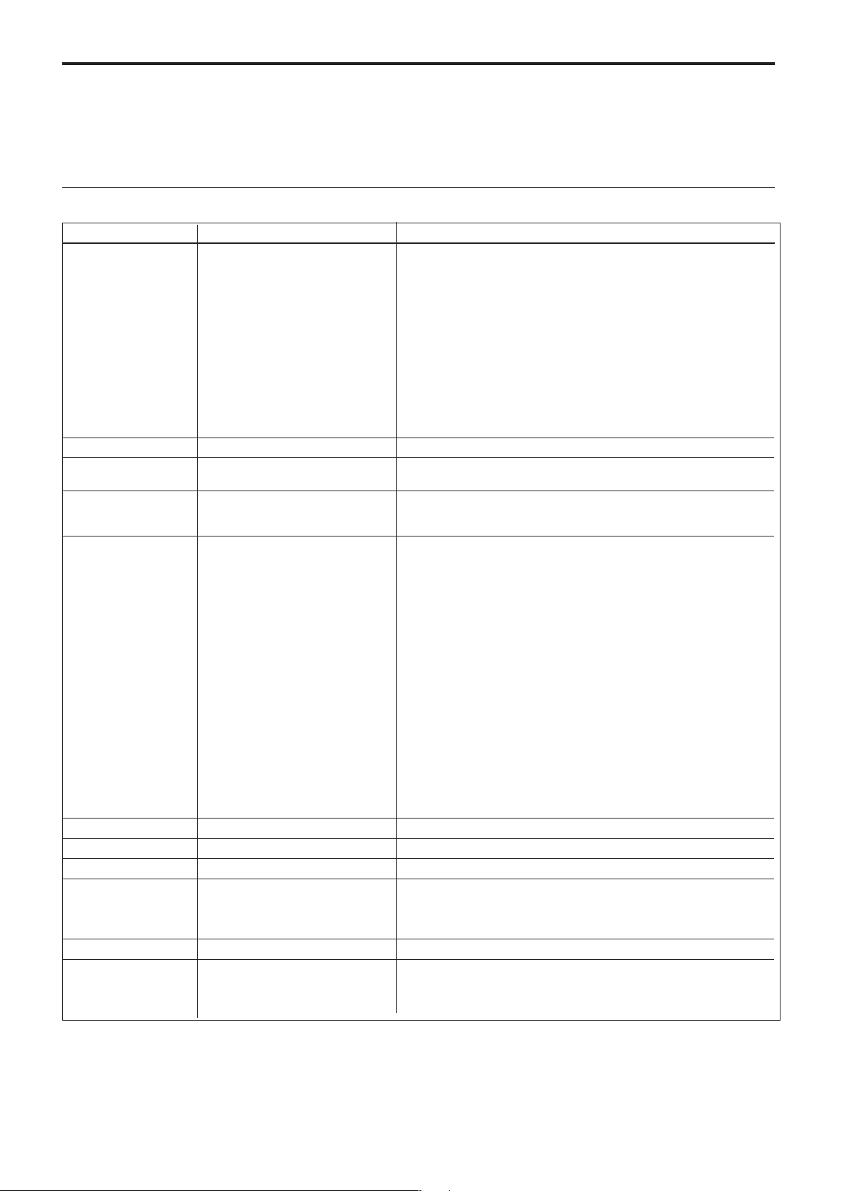
Command Specifications
This section describes the details of control
commands available for the XC-HR90.
User control commands
Command Parameter range Description
BRATE P[CR] P: 0 to 6 Baud rate setting
0: 115200
1: 57600
2: 38400
3: 19200
4: 14400
5: 9600
6: 4800
The newly input baud rate is displayed and OK is displayed, and then the
baud rate is changed to the newly set one.
BRATE[CR] None Displays the baud rate currently set
INIT[CR] None Resets the functions of the camera ( shutter, gain, scan mode
INITIAL[CR] None Resets the functions of the camera to the factory settings. Functions to
SHUTTER P[CR] P: 0 to C (hexadecimal numbers) Shutter setting
SHUTTER[CR] None Reads the shutter setting
GAIN PP[CR] PP: 00 to FF (hexadecimal numbers) Sets the gain
GAIN[CR] None Reads the gain setting
BINNING P[CR] P: 0/1 Sets the binning mode
BINNING[CR] None Reads the binning mode setting
PARTIAL P[CR] P: 0/1 Sets the partial scan mode
and trigger mode) to the factory settings
be reset are those stored in the user memory in addition to the
functions described above.
0: OFF
1: 1/100s
2: 1/125s
3: 1/250s
4: 1/500s
5: 1/1000s
6: 1/2000s
7: 1/4000s
8: 1/10000s
9: 1/25000s
A: 1/50000s
B: 1/100000s
C: Trigger pulse width control
0: Binning OFF
1: Binning ON
0: Partial scan OFF
1: Partial scan ON
33
Page 34
Camera Control Command
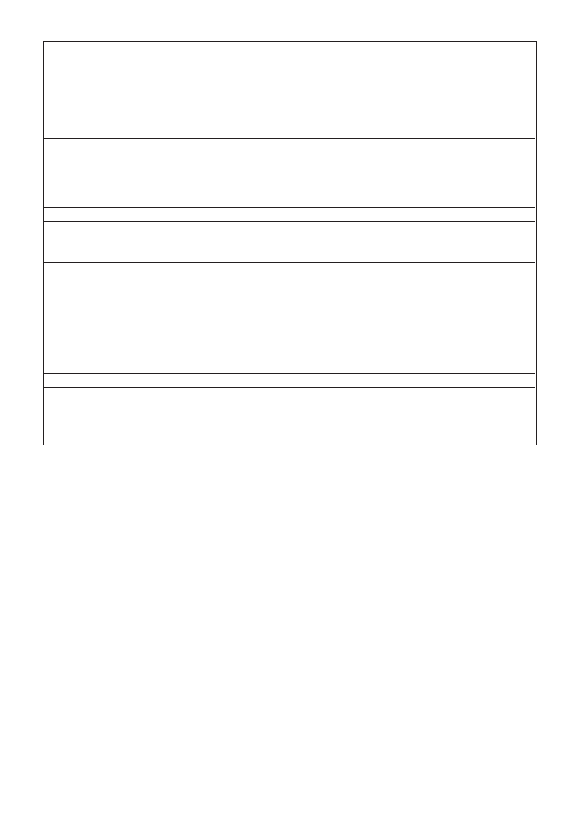
Command Parameter range Description
PARTIAL[CR] None Reads the partial scan mode setting
AREA FR[CR] F: 0 to F (Hexadecimal numbers) Sets the partial scan area
R: 0 to F (Hexadecimal numbers) The parameters are indicated by hexadecimal numbers. The number of
AREA[CR] None Reads the partial scan area
MODE P[CR] P: 0 to 3 Sets the trigger mode.
MODE[CR] None Reads the trigger mode
VERSION[CR] None Reads the version of the firmware of the camera
Maa,dd[CR] aa: 00 to FF (Hexadecimal numbers) Writes the data indicated by the parameter in the user memory
dd: 00 to FF (hexadecimal numbers)
Maa[CR] aa:00 to FF (hexadecimal numbers) Reads the user memory
FRATE P[CR] P: 0 to 1 Sets the frame rate
FRATE[CR] None Reads the frame rate
INTEXT P[CR] P: 0 to 1 Sets the synchronous mode
INTEXT[CR] None Reads the synchronous mode
TERM P[CR] P: 0 to 1 Sets the 75-ohm termination of the VD/HD input
TERM[CR] None Reads the setting of the 75-ohm termination of the VD/HD input
blocks transferred at the upper high-speed is indicated by the first digit,
and the number of blocks transferred at the lower high-speed is indicated
by the second digit. Set the area within the range of F + R < 16.
0: OFF
1: Restart/Reset
2: Trigger Mode 1
3: Trigger Mode 2
0: 30 fps
1: 15 fps
0: INT
1: EXT
0: 75-ohm termination OFF
1: 75-ohm termination ON
34
Page 35

Main Specifications
Items without specific conditions indicated are the
values set at the factory.
Image pickup system
Image pickup device
Number of effective pixels
Optical black 52 pixels per horizontal scan line
CCD vertical driving frequency
CCD horizontal driving frequency
Cell size 3.75 × 3.75 µm (H/V)
Chip size 6.26 × 5.01 mm (H/V)
Optical and other systems
Lens mount C-mount
Flange back 17.526 mm
Synchronization system
External synchronization input/output
Allowable frequency deviation of external
H Jitter Less than 20 ns
1
/3 type interline transfer PS CCD
1296 × 966 (H/V)
At 30 fps: 29.7 kHz ±1%
At 15 fps: 14.85 kHz ±1%
At 30 fps: 49.302 MHz
At 15 fps: 24.651 MHz
Internal/External (automatically
switched according to input
signal)
HD/VD (HD/VD level: 2.5 to 5
Vp-p)
synchronization
±1% (in horizontal synchronous
frequency)
Specifications
Specifications
Minimum illumination
1 lx (with gain manually adjusted to
maximum, F1.4)
Video S/N ratio 56 dB (reference value)
Gain Fixed/Manually adjustable
Gamma compensation
1 (fixed)
White clip 820 mV ±70 mV
Read mode Normal mode/Binning mode
Shutter External trigger shutter
Shutter speed External trigger shutter: 1/4 to
1/100,000 s
Power requirements
+12 V DC (range: +10.5 to +15 V)
Power consumption
2.8 W
Operating temperature
–5 to +45 ˚C (23 to 113 ˚F)
Storage temperature
–30 to +60 ˚C (–22 to +140 ˚F)
Operating humidity
20 to 80% (no condensation)
Storage humidity 20 to 95% (no condensation)
Vibration resistance
10 G (20 to 200 Hz)
Shock resistance 70 G
External dimensions (w/h/d)
29 × 29 × 63.5 mm (1
1
/2 inches)
2
Mass 80 g (2.8 oz)
MTBF 73880 hours (about 8.4 years)
Accessories Lens mount cap (1)
Operating Instructions (1)
Design and specifications are subject to change
without notice.
3
/16 × 1 3/16 ×
Scan lines 990-line/495-line (Normal mode/
Binning mode)
Scanning system Non-interlace
Video output 1.0 Vp-p, sync negative, 75Ω,
unbalanced
Output signal frequency
At 30 fps: 30 Hz/54.1 Hz (Normal
mode/Binning mode)
At 15 fps: 15 Hz/30 Hz (Normal
mode/Binning mode)
Effective lines 1280 × 960 (H/V)
Horizontal resolution
960 TV lines
Sensitivity F5.6 (400 lx with FIX Gain)
IMPORTANT
The nameplate is located on the bottom.
35
Page 36
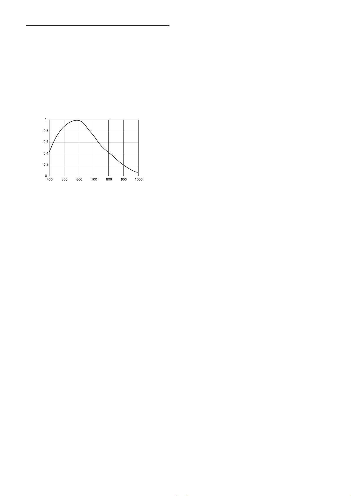
Spectral Sensitivity Characteristics (Typical Values)
An example of spectral sensitivity
characteristics (without taking the characteristics of
the lens and the characteristics of the light source into
consideration):
Specifications
36
Page 37
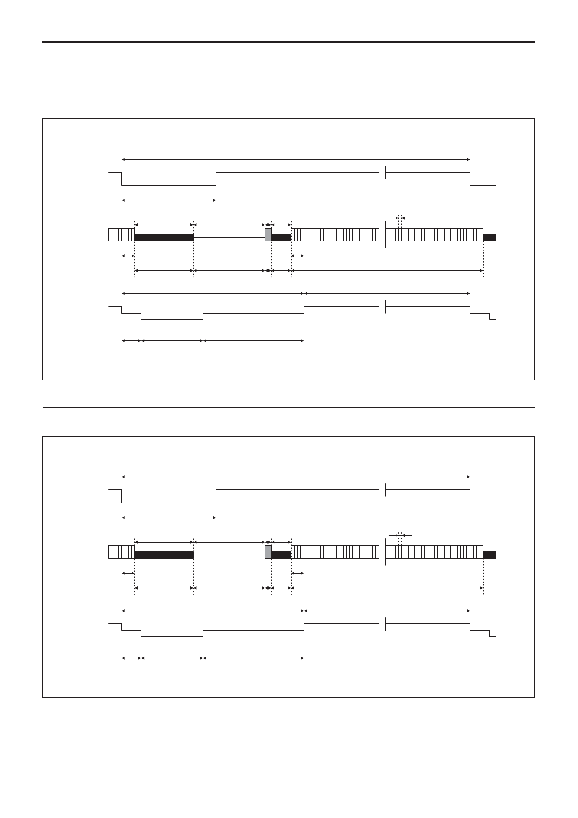
Horizontal Output Waveform Timing Chart
30 fps mode (Normal)
1 horizontal scan period 1660 (33.67 µs)
HD0
166 (3.36 µs)
20.28 ns
CCD
output signal
Camera video
output signal
(Typical value)
40
8
Optical
black
Horizontal blanking period 380
(7.70 µs)
HSYNC 235
76
(1.54 µs)
(4.76 µs)
308
Horizontal
transfer stop
period
Dummy
bits
69
(1.4 µs)
4
12
Optical
black
8
Effective total pixels 1296
Output video period 1280 (25.96 µs)
Specifications
30 fps mode (Binning)
HD0
166 (3.36 µs)
CCD
output signal
Camera video
output signal
(Typical value)
8
Optical
black
Horizontal blanking period 560
HSYNC 235
76
(1.54 µs)
40
(11.35µs)
(4.76 µs)
Values without units indicate the clock counts.
1 horizontal scan period 1840 (37.32 µs)
12
Dummy
bits
249
(5.05 µs)
4
8
Optical
black
488
Horizontal
transfer stop
period
20.28 ns
Effective total pixels 1296
Output video period 1280 (25.96 µs)
Values without units indicate the clock counts.
37
Page 38
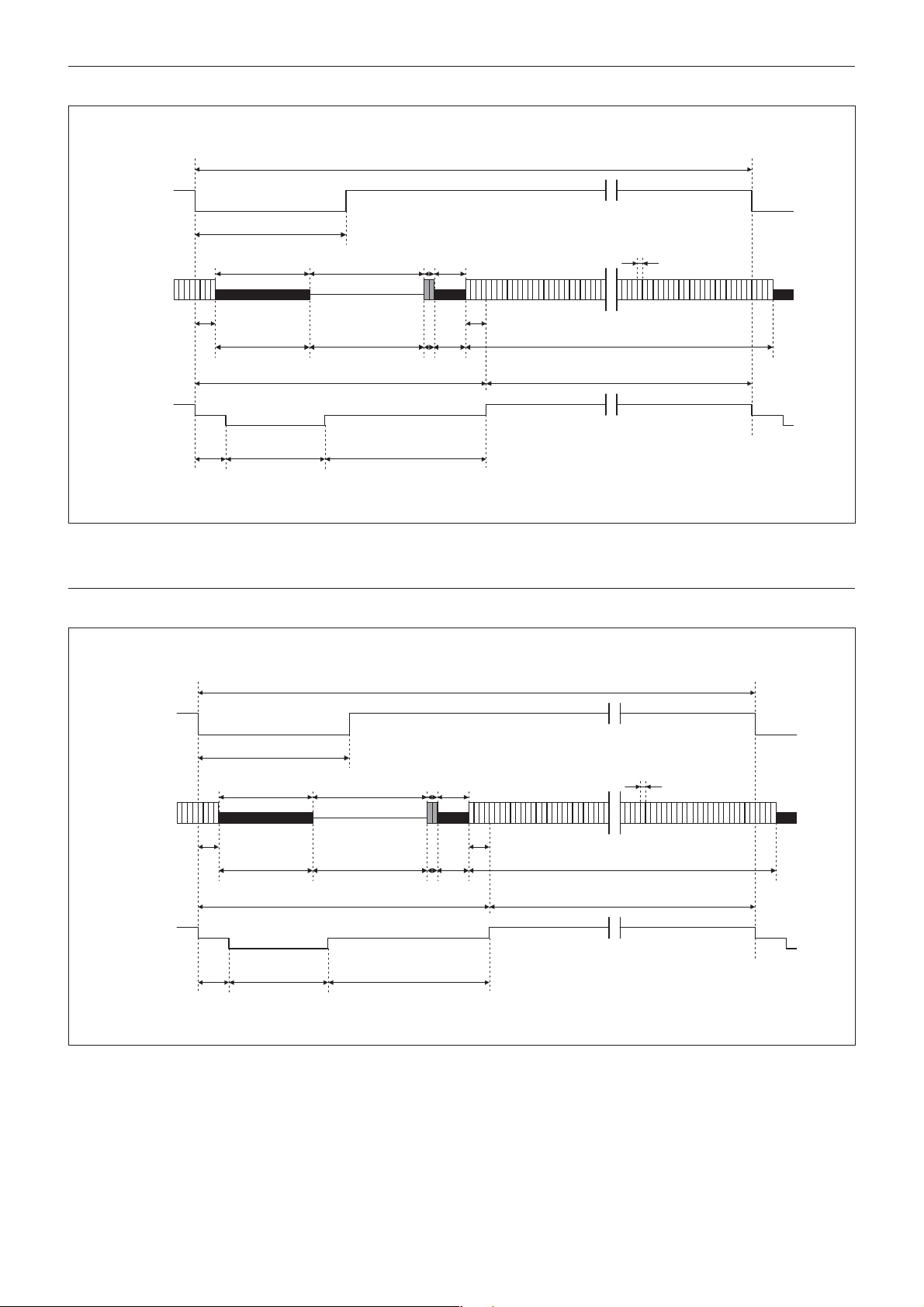
15 fps mode (Normal)
HD0
166 (6.73 µs)
CCD
output signal
Camera video
output signal
(Typical value)
8
Optical
black
Horizontal blanking period 380
HSYNC 235
76
(3.08 µs)
40
(15.41 µs)
(9.53 µs)
1 horizontal scan period 1660 (67.34 µs)
12
Dummy
bits
69
(2.8 µs)
4
8
Optical
black
308
Horizontal
transfer stop
period
Specifications
40.56 ns
Effective total pixels 1296
Output video period 1280 (51.92 µs)
15 fps mode (Binning)
HD0
166 (6.73 µs)
CCD
output signal
Camera video
output signal
(Typical value)
8
Optical
black
Horizontal blanking period 380
HSYNC 235
76
(3.08 µs)
40
(15.41 µs)
(9.53 µs)
Values without units indicate the clock counts.
1 horizontal scan period 1660 (67.34 µs)
12
Dummy
bits
69
(2.8 µs)
4
8
Optical
black
308
Horizontal
transfer stop
period
40.56 ns
Effective total pixels 1296
Output video period 1280 (51.92 µs)
Values without units indicate the clock counts.
38
Page 39
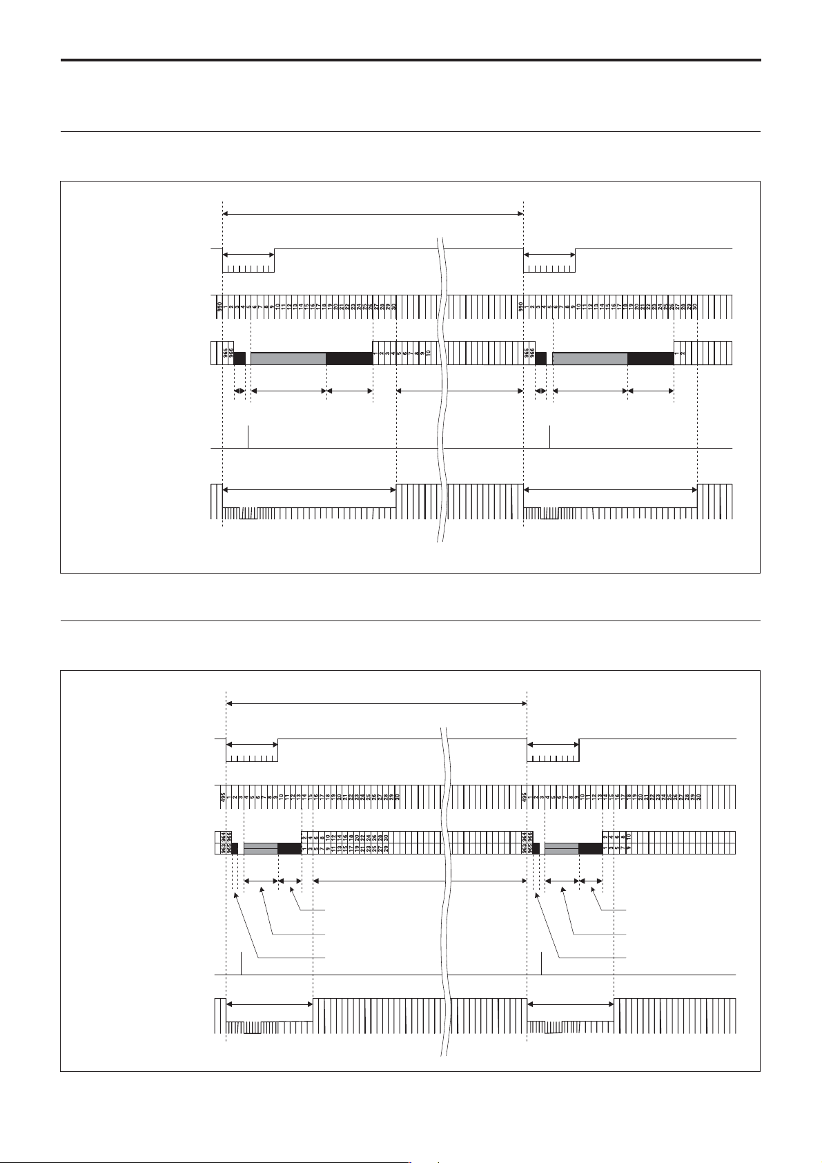
Vertical Output Waveform Timing Chart
30 fps mode (Normal)
990 H
Specifications
VD0
HD0
CCD output signal
SG
Camera video
output signal
(Typical value)
9 H
(303 µs)
2
Optical
black
13
Dummy
bits
Vertical blanking period (30 H)
(1010 µs)
8
Optical
*
black
*: The transfer stop period is included in the dummy bits.
960
(303 µs)
Optical
black
9 H
2
13 8
Dummy
bits*
Vertical blanking period (30 H)
(1010 µs)
Optical
black
30 fps mode (Binning)
VD0
HD0
CCD output signal
SG
Camera video
output signal
(Typical value)
9 H
(335.89 µs
Vertical blanking period (15 H)
)
6
46
(559.81 µs)
Optical black
Dummy bits
1 Optical black
495 H
9 H
(335.89 µs)
480
*
Vertical blanking period (15 H)
(559.81 µs)
4
Optical black
Dummy bits*
1 Optical black
*: The transfer stop period is included in the dummy bits.
39
Page 40
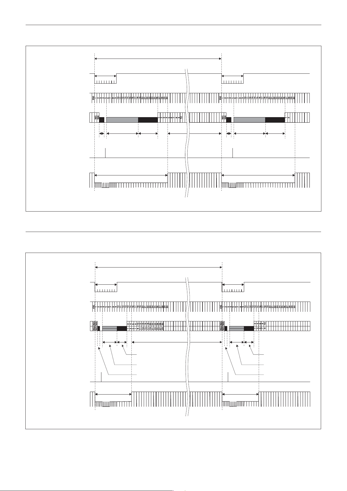
15 fps mode (Normal)
Specifications
990 H
VD0
HD0
CCD output signal
SG
Camera video
output signal
(Typical value)
9 H
(606 µs)
2
Optical
black
13
Dummy
bits
Vertical blanking period (30 H)
(2020 µs)
8
Optical
*
black
*: The transfer stop period is included in the dummy bits.
960
9 H
µ
s)
(606
2
Optical
black
13 8
Dummy
bits*
Vertical blanking period (30 H)
(2020µs)
Optical
black
15 fps mode (Binning)
VD0
HD0
CCD output signal
SG
Camera video
output signal
(Typical value)
9 H
(606 µs
)
6
46
Optical black
Dummy bits
1 Optical black
Vertical blanking period (15 H)
(1010 µs)
495 H
9 H
(606 µs)
480
*
Vertical blanking period (15 H)
(1010 µs)
4
Optical black
Dummy bits*
1 Optical black
*: The transfer stop period is included in the dummy bits.
40
Page 41
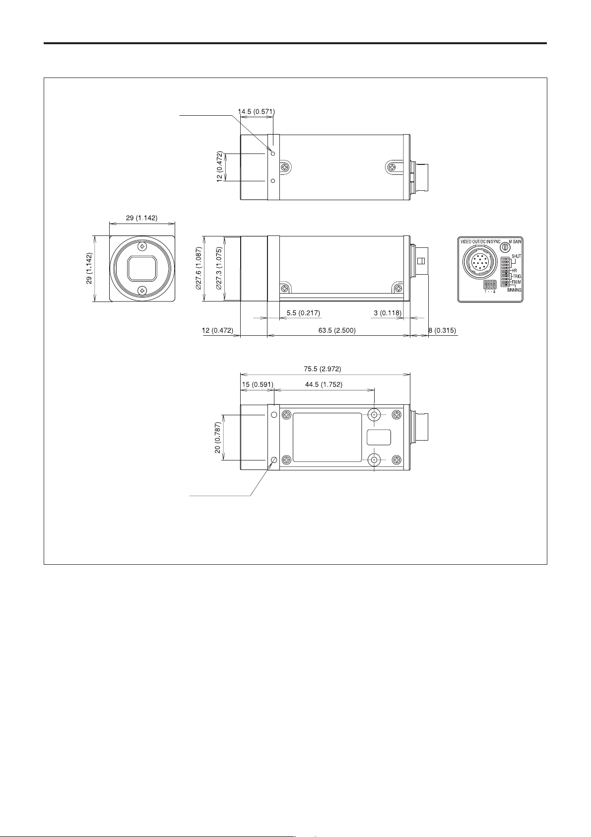
Dimensions
2-M2 depth 3 (0.118)
Specifications
4-M3 depth 4 (0.157)
Sony reserves the right to change specifications of the
products and discontinue products without notice.
Technical information contained herein is for reference
only and does not convey any license by any
implication or otherwise under any intellectual
property right or other right of Sony or third parties.
Sony cannot assume responsibility for any right
infringements arising out of the use of this
information.
Unit: mm (inches)
41
 Loading...