

Page 1
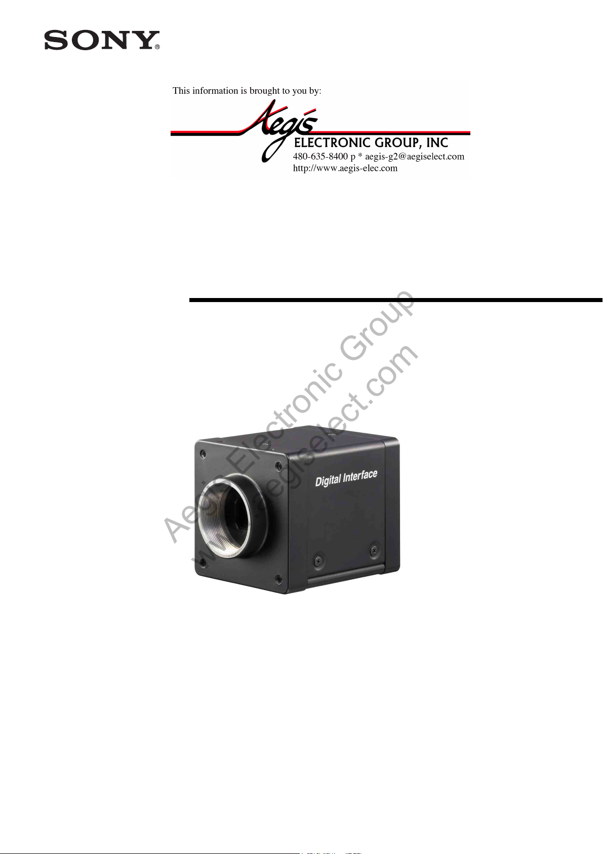
Digital Video
Aegis Electronic Group
www.aegiselect.com
Camera Module
A-E7D-100-11 (1)
Technical Manual
XCG-H280E
XCG-H280CR
© 2012 Sony Corporation
Page 2
Table of Contents
Aegis Electronic Group
www.aegiselect.com
For More Information Please Call Aegis Electronic Group, Inc. * (888) 687-6877 Phone * [email protected] * http://www.aegis-elec.com
Overview
Features .................................................................. 3
Notes on Operation ................................................ 4
Typical CCD Phenomena ..................................... 4
System Components .............................................. 5
Connection ............................................................. 6
Location and Function of Parts and
Operation ............................................................... 7
Front/Top/Bottom ............................................... 7
Rear .................................................................... 7
Using a Tripod .................................................... 8
Connecting the Cables ....................................... 8
GPO Output Specifications ................................ 8
GPI Input Specifications .................................... 8
Trigger Input Specifications ............................... 8
Network
Network Settings ................................................. 10
Using Persistent IP ........................................... 10
Using DHCP .................................................... 10
Using LLA ....................................................... 10
Packet Size ....................................................... 10
Packet Delay ..................................................... 10
Chunk Data ..........................................................23
Control Operations
Camera Control Registers ...................................24
User Set Registers ................................................33
Default Value List ................................................36
Max/Min Value List .............................................40
Specifications
Specifications ........................................................42
Appendix
Spectral Sensitivity (Relative Response)
Parameters ............................................................44
Dimensions ............................................................45
Functions
Reset Functions .................................................... 11
Camera Reset ................................................... 11
Camera Setting Reset (Initializing) .................. 11
Triggering ............................................................. 11
Trigger Operations ........................................... 11
Trigger Edges and Width ................................. 12
Special Trigger Modes ..................................... 12
External Trigger Signals and Timing of
Shooting ......................................................... 13
Trigger Shift ..................................................... 14
Trigger Inhibit .................................................. 14
Vertical Binning (XCG-H280E) ......................... 15
Horizontal Binning (XCG-H280E) .................... 15
Partial Scan .......................................................... 16
Gain ...................................................................... 17
White Balance/Pixel Gain (XCG-H280CR) ...... 17
Exposure Time ..................................................... 18
Frame Rate Control ............................................ 19
Look-Up Table (LUT) ......................................... 19
GPIO ..................................................................... 20
Line Inverter ..................................................... 21
Line Sources ..................................................... 21
Line Status ........................................................ 21
Memory Shot ....................................................... 22
User Set/User Memories ..................................... 22
2
Page 3
Overview
Aegis Electronic Group
www.aegiselect.com
For More Information Please Call Aegis Electronic Group, Inc. * (888) 687-6877 Phone * [email protected] * http://www.aegis-elec.com
The XCG-H280E/H280CR is a digital video camera
module that uses a 2/3-inch 2,830,000-pixel (effective)
progressive scan CCD and supports 1000BASE-T
interface.
Conforming to GigE Vision standards (Ver. 1.2), the unit
is capable of transmitting uncompressed images via a
LAN cable at high efficiency.
Furthermore, the“EXview HAD CCD II” that has
sensitivity in near-infrared domains and supports Full
HD is employed, permitting image acquisition at 32 fps
and shooting of fast-moving objects.
Features
High-quality and high-speed image
capturing
XCG-H280E: video camera module incorporated with
2/3-inch 2,830,000-pixel progressive scan CCD
XCG-H280CR: color video camera module
incorporated with 2/3-inch 2,830,000-pixel progressive
scan CCD
Image Buffer (Memory Shot) function
Images exposed from the sensor can be stored in built-in
memory of the unit. and read using the host PC when
required.
Overview
High-precision and high-speed image
acquisition
32 fps (1,920×1,080 (with default setting))
26 fps (1,920×1,440 (with full resolution))
“EXview HAD CCD II” that has sensitivity in
near-infrared domains
Readout modes
Normal/Binning functions (XCG-H280E)/Partial Scan
Trigger functions
Bulk Trigger/Sequential Trigger/Trigger Delay
Switching an Output Bit Length
You can select 8 bit output (default setting), 10 bit
output, or 12 bit output.
Binarization
Outputs a binarized image. The threshold can be
changed.
Frame rate control
You can change the frame rate while maintaining the
shutter setting. This is useful when you want to reduce
packet sizes per time by lowering the frame rate and
reduce network traffic.
3
Page 4
Notes on Operation
Aegis Electronic Group
www.aegiselect.com
For More Information Please Call Aegis Electronic Group, Inc. * (888) 687-6877 Phone * [email protected] * http://www.aegis-elec.com
Typical CCD Phenomena
Overview
Power supply
Use a stable power source free from ripple or noise.
Locations for operation and storage
Avoid operation or storage in the following places.
• Extremely hot or cold locations. Recommended
temperature range for operation is 0 °C to 40 °C
(32 °F to 104 °F).
• Locations subject to strong vibration or shock.
• Near generators of strong electromagnetic radiation
such as TV or radio transmitters.
Care
Use a blower to remove dust from the surface of the lens
or optical filter. Clean the exterior with a soft, dry cloth.
If the camera is very grimy, apply a cloth soaked in a
mild detergent then wipe with a dry cloth. Do not apply
organic solvents such as alcohol or benzine which may
damage the finish.
Note on laser beams
Laser beams may damage a CCD. You are cautioned
that the surface of a CCD should not be exposed to
laser beam radiation in an environment where a laser
beam device is used.
The following effects on the monitor screen are
characteristic of CCD cameras.
They do not indicate any fault with the camera module.
Smear
This occurs when shooting a very bright object such as
electric lighting, the sun, or a strong reflection.
This phenomenon is caused by an electric charge
induced by infrared radiation deep in the photosensor. It
appears as a vertical smear, since the CCD imaging
element uses an interline transfer system.
Vertical aliasing
When you shoot vertical stripes or lines, they may
appear jagged.
Blemishes
A CCD image sensor consists of an array of individual
sensor elements (pixels). A malfunctioning sensor
element will cause a single pixel blemish in the picture.
(This is generally not a problem.)
White speckles
While CCD image pickup device is made by an accurate
technique, imperceptible speckless may rarely come up
on the screen due to cosmic rays and so on. This is
connected to the principle of CCD image pickup device,
not a malfunction. And the white speckless are easy to
come up in the following conditions.
• Using the camera in high temperature
• When turning up the gain
• With slow-shutter settings
Blooming
This is a phenomenon in which the light from very
bright objects appears to overflow into neighboring
areas in an image.
Level differences between left and right
as well as top and bottom
As the CCD used in the camera adopts a 4-channel
output system, the image area is divided into quarters to
be output individually. Sometimes level differences
among these four sections may occur or border lines
may be seen vertically or horizontally at the center of the
screen, depending on the setting mode of the camera.
This is not a malfunction.
Note
If strong light enters a wide area of the screen, the screen
may become dark.
This is not a malfunction. If this occurs, avoid strong
light or adjust the lens iris to reduce the light amount.
4
Page 5
System Components
Aegis Electronic Group
www.aegiselect.com
For More Information Please Call Aegis Electronic Group, Inc. * (888) 687-6877 Phone * [email protected] * http://www.aegis-elec.com
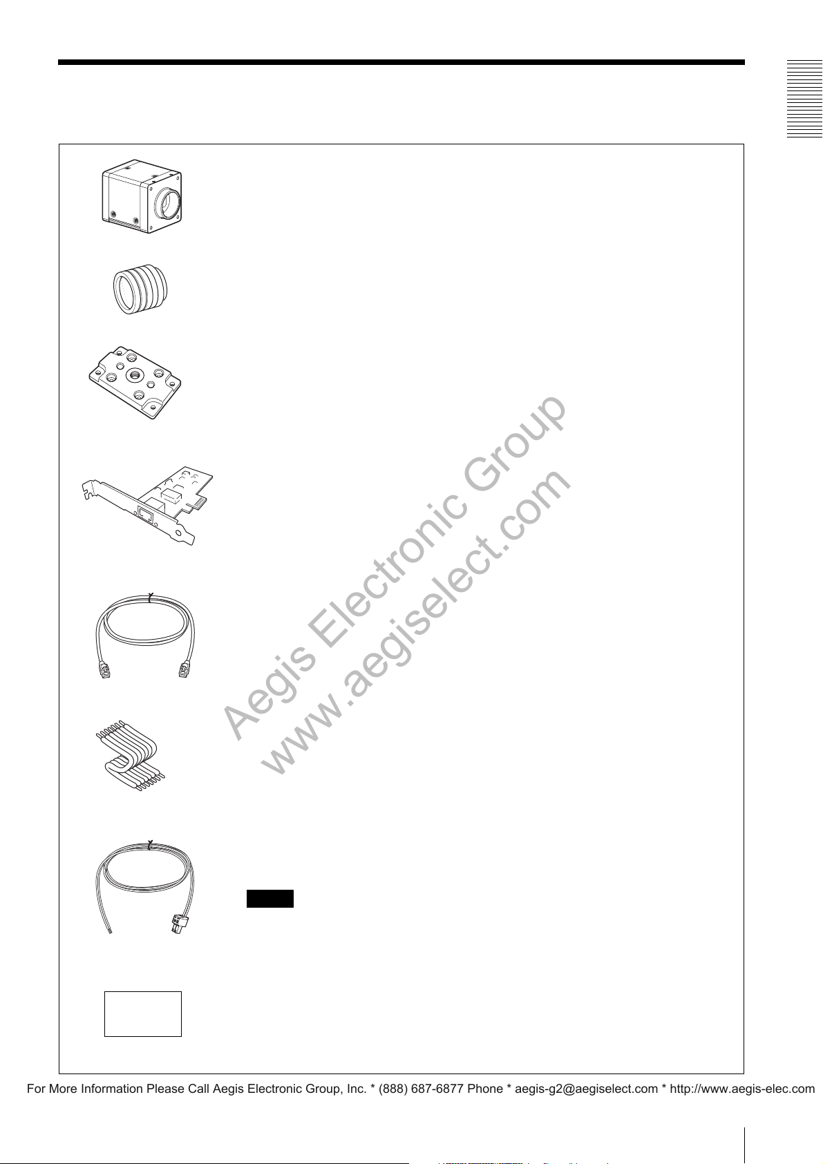
The Camera Module system comprises the following optional products.
This is a small-size, high-resolution, video camera module using a progressive scan CCD image
sensor.
Camera Module
Use a high-resolution lens.
C-mount lens
This attaches to the bottom of the camera module to fix the camera module to a tripod.
VCT-ST70I
tripod adaptor
Install the board in the expansion slot of the host device (ex: computer). Select a card that is
appropriate for your system and that supports 1000BASE-T and jumbo packets.
Overview
Network card
(commercially available)
LAN cable
(commercially available)
Electric wires for signal inputs
(commercially available)
Power supply cable (The 2-pin
connector is supplied as an
accessory.)
This cable connects to the RJ45 connector on the rear panel of the camera module. Image/control
signals are transmitted via this cable. Select a LAN cable that supports 1000BASE-T (CAT5e or
higher cable standard).
Depending on the attributes of the LAN cable, images may become less clear and the camera
module may become unstable. Be sure to use a LAN cable that has sufficient noise reduction.
To be connected to the 7-pin GPIO
Attach commercially available electric wires to the connector to be connected to the power
receptacle.
Note
Use electric wires allowed for DC 20 V or higher and 0.5 A or higher.
Use a power supply allowed for DC 10.5 V to DC 15 V or higher and 1 A or higher.
DC power supply
(commercially available)
5
Page 6
Connection
Aegis Electronic Group
www.aegiselect.com
For More Information Please Call Aegis Electronic Group, Inc. * (888) 687-6877 Phone * [email protected] * http://www.aegis-elec.com
Overview
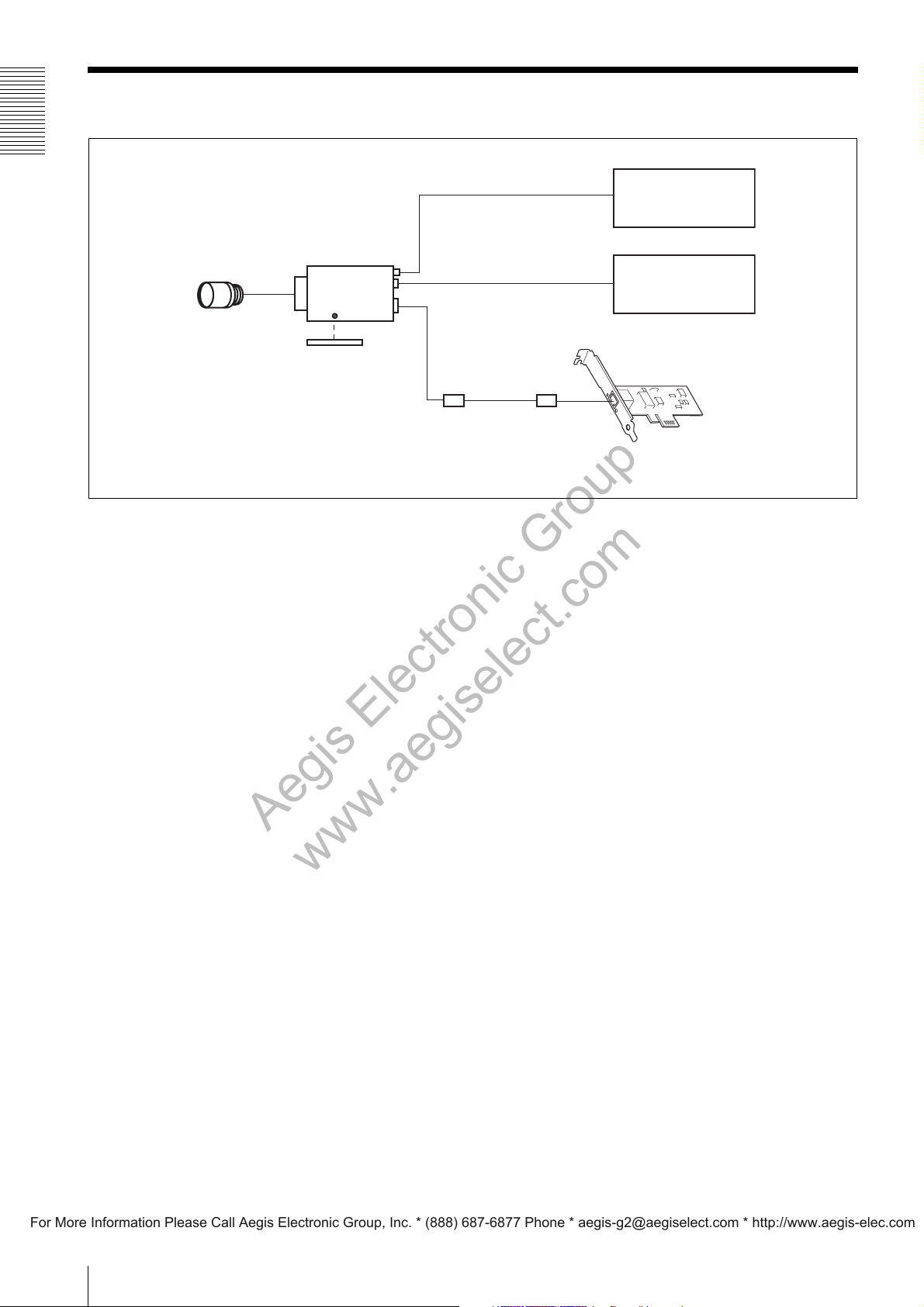
C-mount lens*
XCG-H280E/
XCG-H280CR
Tripod adaptor
VCT-ST70I
Power supply cable (The 2-pin connector
is supplied as an accessory.)
Electric wires for signal inputs
(commercially available)
LAN cable
DC power supply
(commercially available)
Signal generator
or
Converter box
Network card
* Use a high-resolution lens.
6
Page 7
Location and Function of Parts and Operation
Aegis Electronic Group
www.aegiselect.com
For More Information Please Call Aegis Electronic Group, Inc. * (888) 687-6877 Phone * [email protected] * http://www.aegis-elec.com
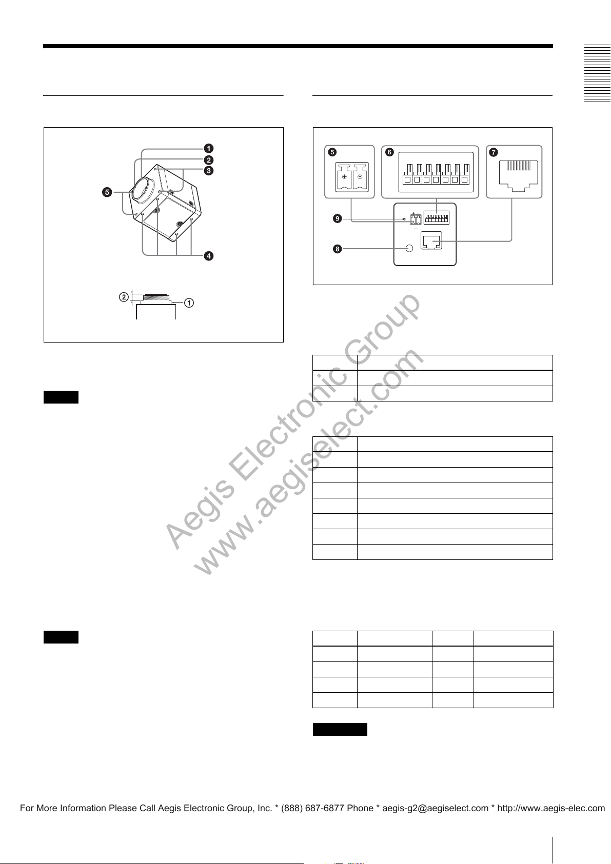
Front/Top/Bottom
a Lens mount (C-mount)
Attach any C-mount lens or other optical equipment.
Note
Rear
2341
567
WIRING
1234567
I/O
CLASS
1000BASE-T
2
DC 12V
e DC 12V (DC power input) connector
Connect the DC power cord to input the +12 V DC
power supply.
The pin configuration of this connector is as follows.
Pin No. Signal
++12V
– GND
12345678
Overview
The lens must not project more than 10 mm (13/32 inch)
from the lens mount.
1 Lens mount face 2 10 mm (13/32 inch) or less
b Guide screw holes (Top)
c LED light screw holes
Use these screw holes to attach the LED light to the
camera module.
Use an adapter appropriate for the LED light as required.
d Guide screw holes/Tripod screw holes (bottom)
These precision screw holes are for locking the camera
module. Locking the camera module into these holes
secures the optical axis alignment.
When using a tripod, use these four screw holes to attach
a VCT-ST70I tripod adaptor.
Note
Use the screws (M3 × 8 (4)) supplied with the tripod
adaptor when installing it on the camera module.
f I/O (Input/Output) connector
Pin No. Signal
1GPO[1]
2GPO[2]
3 TRIGGER IN[1]
4 TRIGGER IN[2]
5 GPI[1]
6 GPI[2]
7 GND
g RJ45 connector
You can connect a LAN cable to this connector to
control the camera module from a host device to output
image to a host device.
Pin No. Signal Pin No. Signal
1TP1 + 5TP3 –
2TP1 – 6TP2 –
3TP2 + 7TP4 +
4TP3 + 8TP4 –
CAUTION
For safety, do not connect the connector for peripheral
device wiring that might have excessive voltage to this
port. Follow the instructions for this port.
7
Page 8
Overview
CLASS
2
WIRING
I/O
1234567
DC
12V
1000BASE-T
Aegis Electronic Group
www.aegiselect.com
For More Information Please Call Aegis Electronic Group, Inc. * (888) 687-6877 Phone * [email protected] * http://www.aegis-elec.com
h Status LED (Green)
When power is on, this LED lights up.
i Reset switch
This reformats the network settings.
Using a Tripod
To use the tripod, install the tripod adaptor VCT-ST70I
(not supplied) on the camera module.
Use a tripod screw with a protrusion (4) extending from
the installation surface, as follows, and tighten it, using
a screwdriver.
4.5 mm to 5.5 mm
0.18 inches to 0.22 inches
Note
If you install a tripod adapter (not supplied), use the
screws provided.
Connecting the Cables
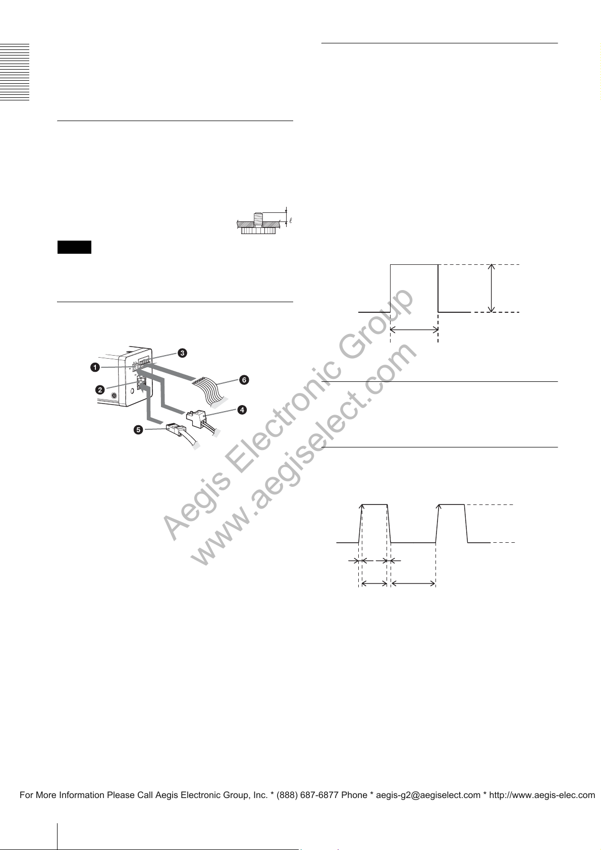
GPO Output Specifications
When exposure output is selected, signal output is valid
during image sensor exposure. When strobe control
output is selected, output signal timing and pulse width
can be precisely set to control external devices such as
strobes connected to the camera. The sensor readout
signal indicates that the imager is outputting images. If
you select user output, the High/Low-fixed output is
obtained according to the register set value. The polarity
of the GPO output signal can be changed, using the line
selector. When connecting the GPO output signal,
terminate the connection with 10 kΩ
impedance.
The figure shows an example in which the polarity of
GPO output is positive.
or higher
4.8 to 5.2 V
Connect the DC power cord to the DC 12V connector
and the LAN cable to the RJ45 connector respectively.
Connect the I/O cable to the I/O connector.
a DC 12V connector
b RJ45 connector
c I/O connector
d DC power cord
e LAN cable
Exposure Time
GPI Input Specifications
Be sure to use an external power supply between +5 and
+24 V DC in combination with resistance.
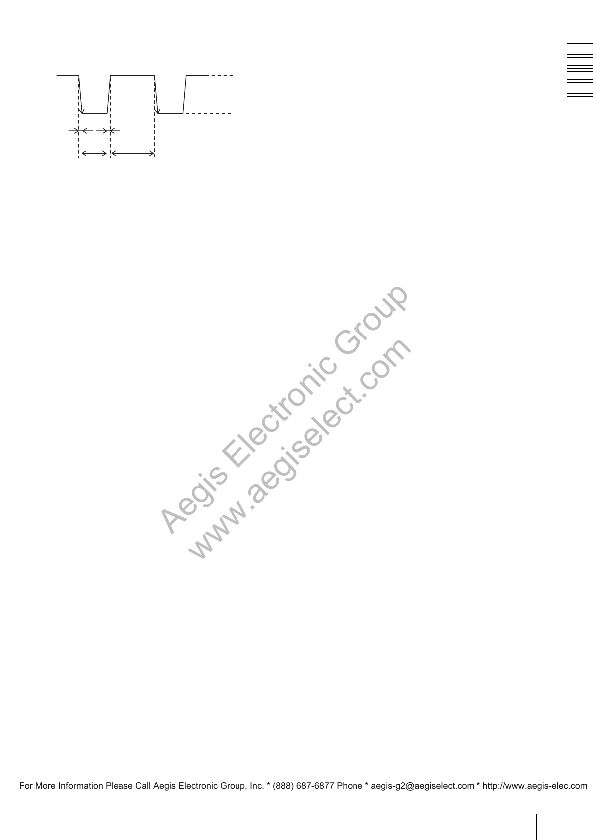
Trigger Input Specifications
When trigger input polarity is positive
2 to 24 V
0 to 0.4 V
2.0 µs
max.
10 µs
to 2 s
2.0 µs
max.
100 µs or
more
f I/O cable
Connect the DC power cord to the DC power supply
source, and the LAN cable to the camera module
interface board of the host device. Connect the I/O cable
to the I/O device.
8
Page 9
When trigger input polarity is negative
Aegis Electronic Group
www.aegiselect.com
For More Information Please Call Aegis Electronic Group, Inc. * (888) 687-6877 Phone * [email protected] * http://www.aegis-elec.com
2 to 24 V
0 to 0.4 V
2.0 µs
max.
10 µs
to 2 s
The voltage values described in the above diagram are
the values when the terminating impedance is 10 kΩ or
more.
2.0 µs
max.
100 µs
or more
Overview
9
Page 10
Network
Aegis Electronic Group
www.aegiselect.com
For More Information Please Call Aegis Electronic Group, Inc. * (888) 687-6877 Phone * [email protected] * http://www.aegis-elec.com
Network
Network Settings
For the camera to be connected to a network, the
following address data must be properly specified:
• IP address
• Subnet mask
• Default gateway
The camera provides the following three methods for the
address data setting:
• Using Persistent IP
• Using DHCP
• Using Link Local Address (LLA)
Using Persistent IP
Use this method when the IP address to be assigned to
the camera has been specified in advance. When using
the persistent IP, subnet mask and default gateway
settings are also required.
Using DHCP
The camera is equipped with a function to automatically
obtain an IP address by communicating with a DHCP
server on a network. When using the DHCP method for
IP address setting, the subnet mask and default gateway
values automatically obtained from the DHCP server are
also used.
Packet Delay
The delay amount to be inserted between packets can be
set when sending them to a network. By increasing the
packet delay, you can reduce the network bandwidth that
the camera uses for sending packets. However, as the
amount of data sent in a certain time is decreased with
increased delay, the frame rate of output images of the
camera may be consequently decreased.
Notes
• Any persistent IP address can be entered, but the
camera may become unable to be detected, depending
on the IP address setting. If this occurs, use a tool for
issuing ForceIP and set a persistent IP address again.
• The packet size and payload size (amount of data per
frame) settings that conform to the forbidden
condition described below are invalid. If such invalid
setting is made, an error occurs. In such a case, change
the packet size or payload size to an appropriate value.
Forbidden condition: The remainder is 4 or 8 when the
payload size is divided by (packet size – 36).
The payload size (in bytes) is calculated from the
image size (Width × Height) and pixel format as
follows:
Mono8: Width × Height
Mono10Packed/Mono12Packed: Width × Height ×
1.5
• When setting the parameters (Width, Height, and
PixelFormat) for calculating the payload size, stop
camera image output beforehand.
Using LLA
If neither Persistent IP nor DHCP is used, or if an IP
address cannot be obtained from the DHCP server, the
IP address is determined by LLA. The IP address
determined by LLA will be 169.254.XXX.YYY, with
XXX and YYY automatically specified.
In addition, the following network settings can be
changed.
• Packet size
• Packet delay
Packet Size
The amount of image data per packet can be set in bytes.
To permit the camera to operate properly, set the packet
size to a value less than the MTU of the network device
connected to the camera.
10
Page 11
Functions
Aegis Electronic Group
www.aegiselect.com
For More Information Please Call Aegis Electronic Group, Inc. * (888) 687-6877 Phone * [email protected] * http://www.aegis-elec.com
Reset Functions
This camera has the following reset functions for
returning operations to the initial conditions:
• Camera reset
• Camera setting reset
Camera Reset
Reset is executed by accessing the DeviceReset register.
The camera is restarted. This is the same operation as
that when you turn the power off then back on again.
Camera Setting Reset (Initializing)
This reset is executed by holding the reset button on the
rear panel pressed for more than three seconds. Then the
camera is restarted.
The following network settings are returned to their
default values with this reset operation:
Packet size, packet delay, use/nonuse setting of the
persistent IP address and the set values (IP address,
subnet mask, default gateway), use/nonuse setting of
DHCP
In addition, the camera settings are changed as follows:
“UserSetDefaultSelector” is set to “Default.”
Triggering
Trigger Operations
The camera can shoot images according to trigger
signals supplied from external devices. If no operation
with a trigger signal is selected, the camera performs
free-run image output according to the exposure time
and frame rate settings. In Free-Run mode, the frame
rate is automatically adjusted to the maximum value
according to the exposure time setting. The frame rate
can also be fixed when required. The sensor output
shown in the figures below is a signal (SensorReadOut)
which indicates that the imager output is valid. The
signal can be fed out from the GPIO-OUT connector.
External trigger enabled
Setting parameter: TriggerMode = On
Trigger signal
Exposure
Sensor output
External Trigger disabled/Free Run mode
(Frame Rate Auto adjustment)
Setting parameters: TriggerMode = Off
AcquisitionFrameRateAuto = On
Functions
Trigger signal
Exposure
Sensor output
Automatically adjusted to
minimize the image interval
External Trigger disabled/Free Run mode
(Frame Rate fixed)
Setting parameters: TriggerMode = Off
AcquisitionFrameRateAuto = Off
AcquisitionFrameRate = T
Trigger signal
Exposure
Sensor output
1/T
11
Page 12

Trigger Edges and Width
Aegis Electronic Group
www.aegiselect.com
For More Information Please Call Aegis Electronic Group, Inc. * (888) 687-6877 Phone * [email protected] * http://www.aegis-elec.com
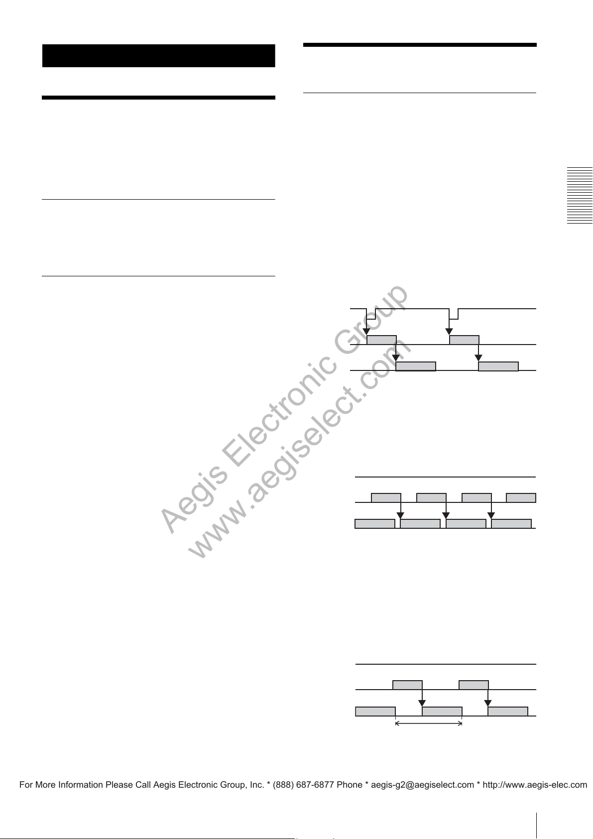
When the camera is in Trigger Edge mode, it starts
shooting by detecting the rising or falling edge of a
trigger signal and performs shooting for the exposure
time specified in advance.
In Trigger Width mode, shooting is performed by
detecting the effective period of the trigger signal as the
exposure time.
Line5_GPI1/Line6_GPI2/
Line3orLine4/Line3andLine4
SpecialTriggerActivation =
RisingEdge/FallingEdge
(“FallingEdge” selected in the
figure below)
NumberOfMemoryForSpecialTrig
gerMode = 1 to 16 (“3” selected
in the figure below)
Functions
Trigger Edge
Setting parameters: ExposureMode = Timed
TriggerActivation = RisingEdge/
FallingEdge (“FallingEdge”
selected in the figure below)
Trigger signal
Exposure
Sensor output
Trigger Width
Setting parameter: ExposureMode = TriggerWidth
a
Trigger signal
a
Exposure
Sensor output
b
b
Trigger signal
Exposure
Sensor output
Setting 1
Setting 2 Setting 3
Sequential mode
Setting parameters: TriggerMode = Off
SpecialTriggerMode = Sequential
SpecialTriggerSource = Software/
Line3_TRIG1/Line4_TRIG2/
Line5_GPI1/Line6_GPI2/
Line3orLine4/Line3andLine4
SpecialTriggerActivation =
RisingEdge/FallingEdge
(“FallingEdge” selected in the
figure below)
NumberOfMemoryForSpecialTrig
gerMode = 1 to 16 (“3” selected
in the figure below)
Trigger signal
Special Trigger Modes
In a normal trigger operation, the settings, such as
exposure time, gain and imaging region, must be
changed in advance for each trigger input when shooting
under different conditions. Such setting changes can be
eliminated by activating a special trigger mode which
makes shooting under different conditions easier. Up to
16 configurations of camera settings can be used. There
are two types of special trigger modes: Bulk mode, in
which shooting continues after being started by a trigger
signal, and Sequential mode, in which shooting is
performed each time a trigger signal is detected. The
next exposure will start after the current image output is
completed. Therefore, the second and subsequent
trigger signal inputs in Sequential mode must be more
than 3 msec. after the end of the preceding image output.
Bulk mode
Setting parameters: TriggerMode = Off
SpecialTriggerMode = Bulk
SpecialTriggerSource = Software/
Line3_TRIG1/Line4_TRIG2/
Exposure
Sensor output
For Bulk and Sequential trigger modes, the following
function settings are read from the User Set memory and
reflected:
Image Format Control
•OffsetX
•OffsetY
Acquisition Control
• ExposureTime
Digital I/O Control
• LineInverter
• LineSource
•UserOutputValue
• StrobeActiveTime
• StrobeActiveDelay
Setting 1 Setting 2 Setting 3
12
Page 13
Analog Control
Aegis Electronic Group
www.aegiselect.com
For More Information Please Call Aegis Electronic Group, Inc. * (888) 687-6877 Phone * [email protected] * http://www.aegis-elec.com
•Gain
•BlackLevel
• BlackLevelAdjust
LUT Control
• LUTEnable
•LUTFormat
• BinarizationThreshold
UserSet Control
• UserMemoryValue
Trigger
mode
Trigger Edge Minimum
Trigger Width Minimum
Trigger
Control
Delay
Delay
Exact
Exposure
Time
Time till
starting
exposure
1.5 usec Exposure
1.5 usec Valid period
35 usec Valid period
Duration of
exposure
Time
of Trigger
Width+33
usec
of Trigger
Width
When using Bulk or Sequential trigger mode, note that
the following settings are ignored and have no effect:
Image Format Control
• SensorTaps
• Width
• Height
• BinningHorizontal
• BinningVertical
• PixelFormat
• TestImageSelector
• GainAutoAreaHighlight
• BalanceWhiteAutoHighlight
Acquisition Control
• AcquisitionFrameRate
• AcquisitionFrameRateAuto
• TriggerMode
•TriggerSource
• TriggerInhibit
• TriggerActivation
•TriggerShift
• TriggerControl
•TriggerDelay
• ExposureMode
• ExposureAuto
Trigger Edge
1.5usec
Trigger signal
Exposure
Sensor output
Trigger Width/Minimum Delay mode
Setting parameter: TriggerControl = MinimumDelay
a
Trigger signal
Exposure
Sensor output
1.5
usec
a+33usec
Trigger Width/Exact Exposure Time mode
Setting parameter:TriggerControl =ExactExposureTime
Functions
Analog Control
a
• GainAuto
• BlackLevelAutoBalance
Trigger signal
Exposure
35usec
a
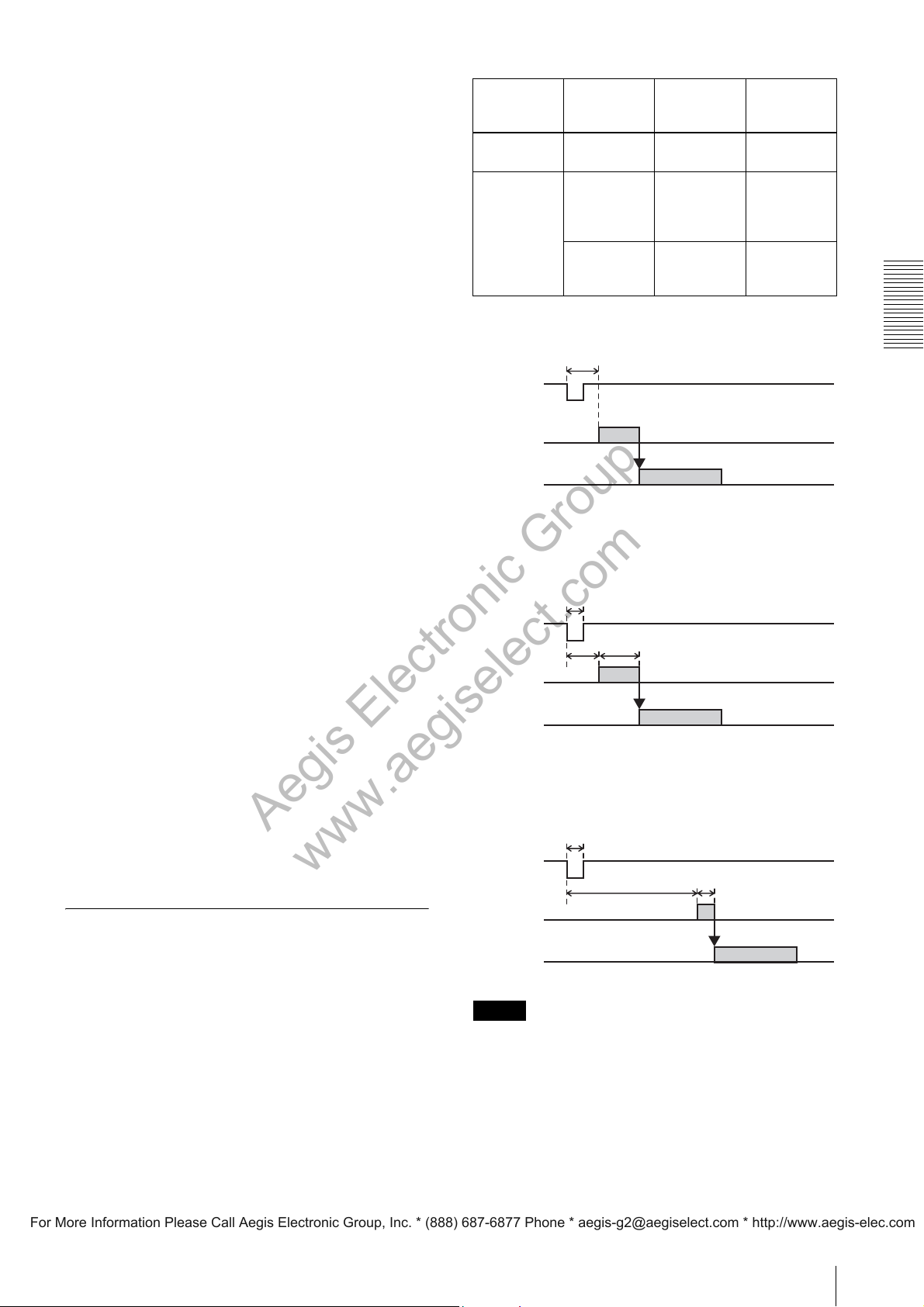
External Trigger Signals and Timing of Shooting
In Trigger Edge mode, the time from when detecting a
trigger signal to when starting exposure is 1.5 usec.
Shooting is performed according to the “Exposure
Time” specified in advance.
In Trigger Width mode, “Minimum Delay” operation or
“Exact Exposure Time” operation can be selected. The
relationship between the time till starting exposure and
the exposure time are shown in the table below.
Sensor output
Note
When Trigger Shift is active, Trigger Width/Exact Time
Exposure mode cannot be selected.
13
Page 14
Functions
Aegis Electronic Group
www.aegiselect.com
For More Information Please Call Aegis Electronic Group, Inc. * (888) 687-6877 Phone * [email protected] * http://www.aegis-elec.com
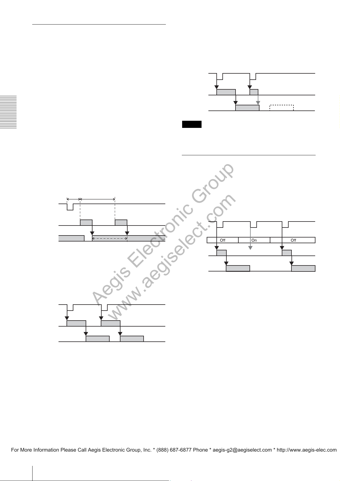
Trigg er Shif t
The camera can perform exposure by the next trigger
even during image transmission (except in Special
Trigger mode). In such case, as the trigger signal can be
a noise source, use the camera with Trigger Shift
activated. When Trigger Shift is active, the time between
trigger input and start of exposure is automatically
adjusted to avoid noise generation, causing a delay of
one line at maximum in starting exposure. When Trigger
Shift is deactivated, the delay adjustment is not made
and exposure always starts with the same timing, but
noise may be mixed into images. Even if Trigger Shift is
active, triggering may be disabled, or exposure may be
defective while an image transmission is in progress and
the next transmission cannot be started. Select a
sufficient trigger interval (see “Trigger Input
Specifications” (page 8)).
Setting parameter: TriggerShift = On
Example of next image transmission
disabled
As image transmission is not completed when the
exposure ends, transmission of the next image cannot be
started. The trigger becomes invalid.
Trigger signal
Exposure
Image output
Note
Trigger Shift cannot be enabled in Trigger Width/Exact
Time Exposure mode.
Next image transmission
starts before transmission of
the previous image is
completed.
x
No image output
Trigger Shift operation (The figure below
shows Trigger Edge mode.)
1.5usec
Trigger signal
Exposure
Image output
To be shifted in this period
1H (26usec)
min 1.5usec
max 27.5usec
Example of next image transmission
enabled
Transmission of the next image can be started as the
previous image transmission is already completed when
the exposure ends.
Trigger signal
Exposure
Next image
transmission starts
after transmission of th e
previous image is
completed.
Trigger Inhibit
This function disables the camera’s trigger input. When
multiple cameras are connected, use this to disable
triggering for only specified cameras or to eliminate
malfunction due to noise mixed in the trigger signal line
from the setup environment.
Setting parameter: TriggerInhibit = On
Trigger signal
Trigger
Inhibit
Exposure
Image output
x
Trigger disabled
Image output
14
Page 15
Vertical Binning (XCG-
Aegis Electronic Group
www.aegiselect.com
For More Information Please Call Aegis Electronic Group, Inc. * (888) 687-6877 Phone * [email protected] * http://www.aegis-elec.com
H280E)
Vertical Binning increases sensitivity and doubles frame
rate by adding vertically adjacent pixel data.
When Vertical Binning is activated, the maximum
vertical image size is halved.
Setting parameter: BinningVertical = 1 (Vertical
Binning Off) / 2 (Vertical Binning On)
Horizontal Binning (XCG-H280E)
Horizontal Binning increases sensitivity by adding
horizontally adjacent pixel data.
When Horizontal Binning mode is activated, the
maximum horizontal image size is halved.
Setting parameter: BinningHorizontal= 1 (Horizontal
Binning Off) / 2 (Horizontal Binning On)
Note
Frame rate is not doubled by activating Horizontal
Binning mode.
Functions
15
Page 16
Partial Scan
Aegis Electronic Group
www.aegiselect.com
For More Information Please Call Aegis Electronic Group, Inc. * (888) 687-6877 Phone * [email protected] * http://www.aegis-elec.com
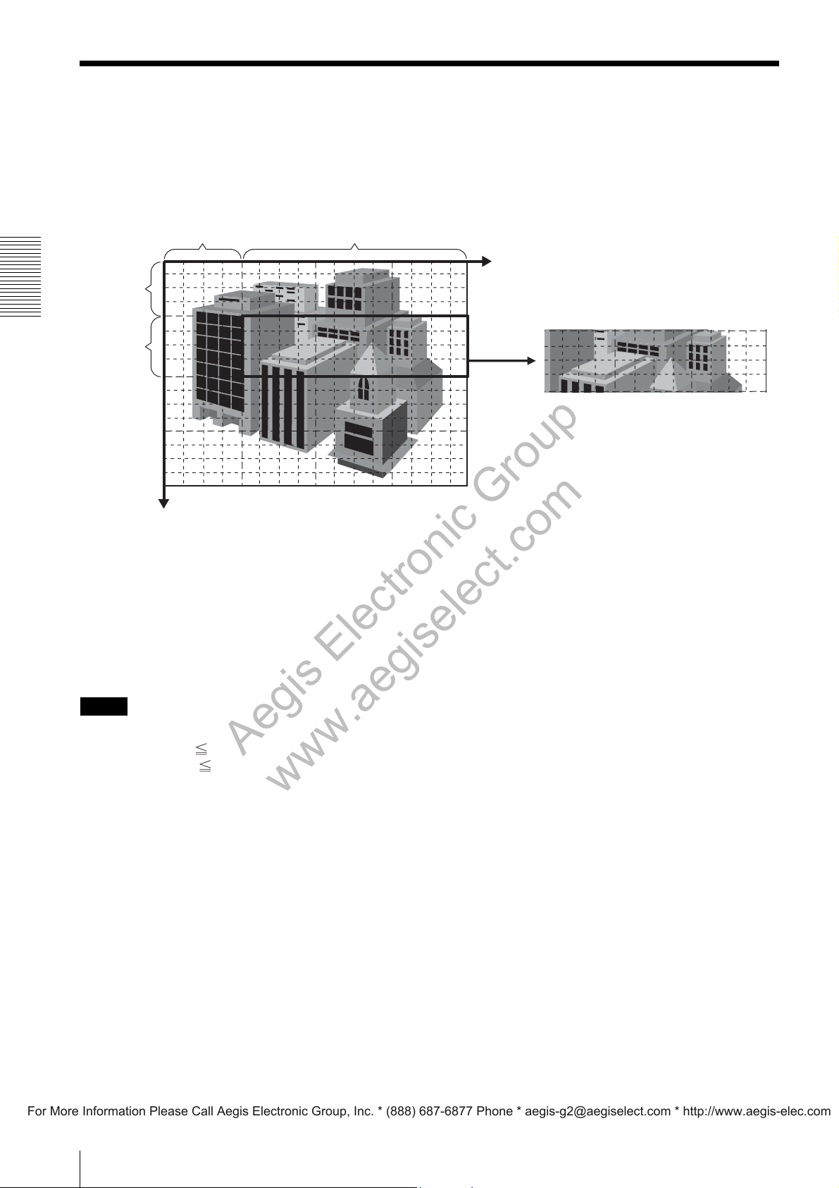
Partial Scan is a function for outputting a user-defined region within the overall image area. The cut-out region for
partial scan is defined by Offset X and Offset Y (which indicate the start point for cutting) as well as Width and Height
(which indicate the area). Contiguous blocks of minimum areas can be selected to define regions. However, the defined
region must be a rectangle. T- and L-shaped regions are invalid. When Vertical Binning or/and Horizontal Binning are
active, the pixels defined by Width, Height, OffsetX, and OffsetY are those after pixel binning.
Functions
OFFSET X
OFFSET Y
HEIGHT
Y (vertical direction)
Setting parameters: Width = 640 to 1920, by 8 pixels (Horizontal Binning Off)
320 to 960, by 4 pixels (Horizontal Binning On)
OffsetX = 0 to 1280, by 2 pixels (Horizontal Binning Off)
0 to 640, by 1 pixel (Horizontal Binning On)
Height = 480 to 1440, by 2 pixels (Vertical Binning Off)
240 to 720, by 1 pixel (Vertical Binning On)
OffsetY = 0 to 720, by 2 pixels (Vertical Binning Off)
0 to 480, by 1 pixel (Vertical Binning On)
WIDTH
X (horizontal direction)
Cutting by Partial Scan
Notes
• When setting Partial Scan mode, observe the following conditions.
Width + OffsetX MaxWidth (1920 with Horizontal Binning Off, 960 with it On)
Height + OffsetY MaxHeight (1440 with Vertical Binning Off, 720 with it On)
• Be aware that the frame rate increases for vertical cut-outs, while the frame rate remains unchanged for horizontal
cut-outs.
• In 4-channel sensor reading, the closer to the center the reading position, the more the frame rate will be improved.
While keeping Height unchanged, OffsetY that provides the maximum frame rate can be obtained with the formula
below:
OffsetY = (MaxHeight – Height)/2
Be sure that MaxHeight is 1440 with Vertical Binning Off and 720 with it On.
16
Page 17
Gain
Aegis Electronic Group
www.aegiselect.com
For More Information Please Call Aegis Electronic Group, Inc. * (888) 687-6877 Phone * [email protected] * http://www.aegis-elec.com
White Balance/Pixel
The camera provides both manual and automatic gaincontrol capabilities.
Manual gain control
For the Tap selected with “GainSelector,” gain can be set
from 0 to 18 dB in increments of 0.0359 dB.
When setting gain for all Taps, select “AnalogAll.”
Setting parameters:GainSelector =AnalogAll/
AnalogTap1/AnalogTap2/
AnalogTap3/ AnalogTap4
Gain[GainSelector] = 0 to 18(dB)
Auto gain control
The camera provides the auto gain control function to
automatically control image brightness according to a
user-specified detection frame and image average level
(variable from 0 to 16383 by 14 bits). The upper and
lower limits of the variable range are adjustable.
If auto gain control is set to “Once,” it automatically
changes to “Off” when the gain reaches the image
average level or the upper or lower limit of the variable
range. With the “Continuous” setting, auto gain control
constantly operates.
Also, the auto gain control detection frame which shows
each area’s image average level can be displayed and
adjusted. The detection frame is defined by Offset X and
Y, Width and Height percentage values (relative to the
[100%] width and height of the output video image).
Gain (XCG-H280CR)
The camera provides the pixel gain control function and
one push white balance function using the pixel gain
control.
Pixel gain control
For the R/G/B Tap selected with “GainSelector,” gain
can be set from 0 to 24 dB.
When setting gain for all Taps, select “DigitalRedAll,”
“DigitalGreenAll,” or “DigitalBlueAll.”
Setting parameters:GainSelector = DigitalRedAll/
DigitalRedTap1/
DigitalRedTap2/
DigitalRedTap3/
DigitalRedTap4/
DigitalGreenAll/
DigitalGreenTap1/
DigitalGreenTap2/
DigitalGreenTap3/
DigitalGreenTap4/
DigitalBlueAll/
DigitalBlueTap1/
DigitalBlueTap2/
DigitalBlueTap3/
DigitalBlueTap4
Gain[GainSelector] = 0 to 24 (dB)
Functions
Setting parameters:GainAuto = Off/Once/Continuous
GainAutoLevel = 0 to 16383
GainAutoSpeed = 1 to 256
GainAutoLowerLimit = 0 to 18(dB)
GainAutoUpperLimit = 0 to 18(dB)
The detection frame is specified using the following
parameters.
Setting parameters:GainAutoAreaHighlight = On/Off
GainAutoAreaWidth = 1 to 100 (%)
GainAutoAreaHeight = 1 to 100 (%)
GainAutoAreaOffsetX = 0 to 99 (%)
GainAutoAreaOffsetY = 0 to 99 (%)
Note
When specifying the detection frame, be sure to observe
the following requirements.
GainAutoAreaWidth + GainAutoAreaOffsetX 100
GainAutoAreaHeight + GainAutoAreaOffsetY 100
One push white balance
For the G level of the user-specified detection frame, the
camera adjusts R level and B level with executing one
command. The white balance detection frame which
detects G level can be displayed and adjusted. The
detection frame is defined by Offset X and Y, Width and
Height percentage values (relative to the [100%] width
and height of the output video image).
Setting parameters:BalanceWhiteAuto = Once
The detection frame is specified using the following
parameters.
Setting parameters: BalanceWhiteAuto AreaHighlight =
On/Off
BalanceWhiteAutoAreaWidth = 1
to 100 (%)
BalanceWhiteAutoAreaHeight = 1
to 100 (%)
BalanceWhiteAutoAreaOffsetX = 0
to 99 (%)
BalanceWhiteAutoAreaOffsetY = 0
to 99 (%)
Even if the above one push white balance is used, the
level may not be specified optimally when color
temperature is low. Use the one push white balance after
the G level is specified using the following.
17
Page 18
Functions
Aegis Electronic Group
www.aegiselect.com
For More Information Please Call Aegis Electronic Group, Inc. * (888) 687-6877 Phone * [email protected] * http://www.aegis-elec.com
Setting parameters:GainSelector = DigitalGreenAll
Gain[DigitalGreenAll] = 3 (dB)
BalanceWhiteAuto = Once
Notes
• When using pixel gain, the output level interval may
not be continuous. This phenomenon occurs when
there is not video output signal that corresponds to the
output step. This is not a malfunction.
• If pixel gain is set to high, noise may be apparent. This
is not a malfunction.
• When specifying the upper or lower limit of the
exposure time, be sure to observe the following
requirements.
BalanceWhiteAutoAreaWidth +
BalanceWhiteAutoAreaOffsetX 100
BalanceWhiteAutoAreaHeight +
BalanceWhiteAutoAreaOffsetY 100
Exposure Time
The camera provides both manual and automatic
exposure control capabilities.
Manual exposure control
Exposure for the specified time is achieved by internal
continuous driving or Trigger Edge operation.
Setting parameter: ExposureTime = 10 to 2,000,000 (us)
Auto exposure control
The camera provides the auto exposure control function
to automatically control exposure time according to a
common user-specified detection frame and image
average level sharing with auto gain control function.
The upper and lower limits of the variable range are
adjustable.
If the auto exposure control is set to “Once,” it
automatically changes to “Off” when the exposure time
reaches the image average level or the upper or lower
limit of the variable range. With the “Continuous”
setting, auto exposure control constantly operates.
When both auto exposure control and auto gain control
are activated, gain is lowered and exposure time is
extended within the variable range.
Setting parameters:ExposureAuto = Off/Once/
Continuous
ExposureAutoSpeed = 1 to 256
ExposureAutoLowerLimit = 10 to
2,000,000 (us)
ExposureAutoUpperLimit = 10 to
2,000,000 (us)
Note
Neither the upper nor lower limits of the exposure time
variable range affect the configurable range of exposure
time setting by manual exposure control.
When specifying the upper or lower limit of the
exposure time, be sure to observe the following
requirements.
ExposureAutoLowerLimit < ExposureAutoUpperLimit
18
Page 19
Frame Rate Control
Aegis Electronic Group
www.aegiselect.com
For More Information Please Call Aegis Electronic Group, Inc. * (888) 687-6877 Phone * [email protected] * http://www.aegis-elec.com
Look-Up Table (LUT)
The camera provides the following two methods for
frame rate control during internal continuous drive
operation.
Auto Frame Rate setting
The fastest frame rate is configured automatically based
on the current Exposure Time and Partial Scan settings.
This is the default frame rate control setting for the
camera.
To increase the frame rate, activate Partial Scan mode.
Depending on whether the exposure time is longer than
the frame period, the frame rate will be reduced
proportionally. Therefore shorten the exposure time as
necessary.
Setting parameter: AcquisitionFrameRateAuto = On
Frame Rate setting
The frame rate can be set manually. However, you
cannot increase the frame rate beyond the fastest setting.
In addition, if the exposure time is longer than the
configured frame period, the frame rate will be reduced
in proportion to the exposure time.
When you want to reduce network traffic, use this
setting to lower the frame rate while maintaining the
same Exposure Time setting.
Setting parameters: AcquisitionFrameRateAuto = Off
AcquisitionFrameRate = 0.0625
to180 (fps)
Frame rate indication
The camera has a frame rate display function for
verifying the frame rate obtained using the above
settings. By using this function, you can confirm that an
anticipated frame rate has been obtained.
Observation parameter: AcquisitionFrameRateActual
The look-up table of the camera consists of 4,096 values,
with 12-bit input and 12-bit output. The look-up table
allows setting an arbitrary gamma curve or binarization.
Selectable from 0: Linear 1: Reverse 2: Binarization 3:
5-Point Linear Interpolated LUT 4: User Setting.
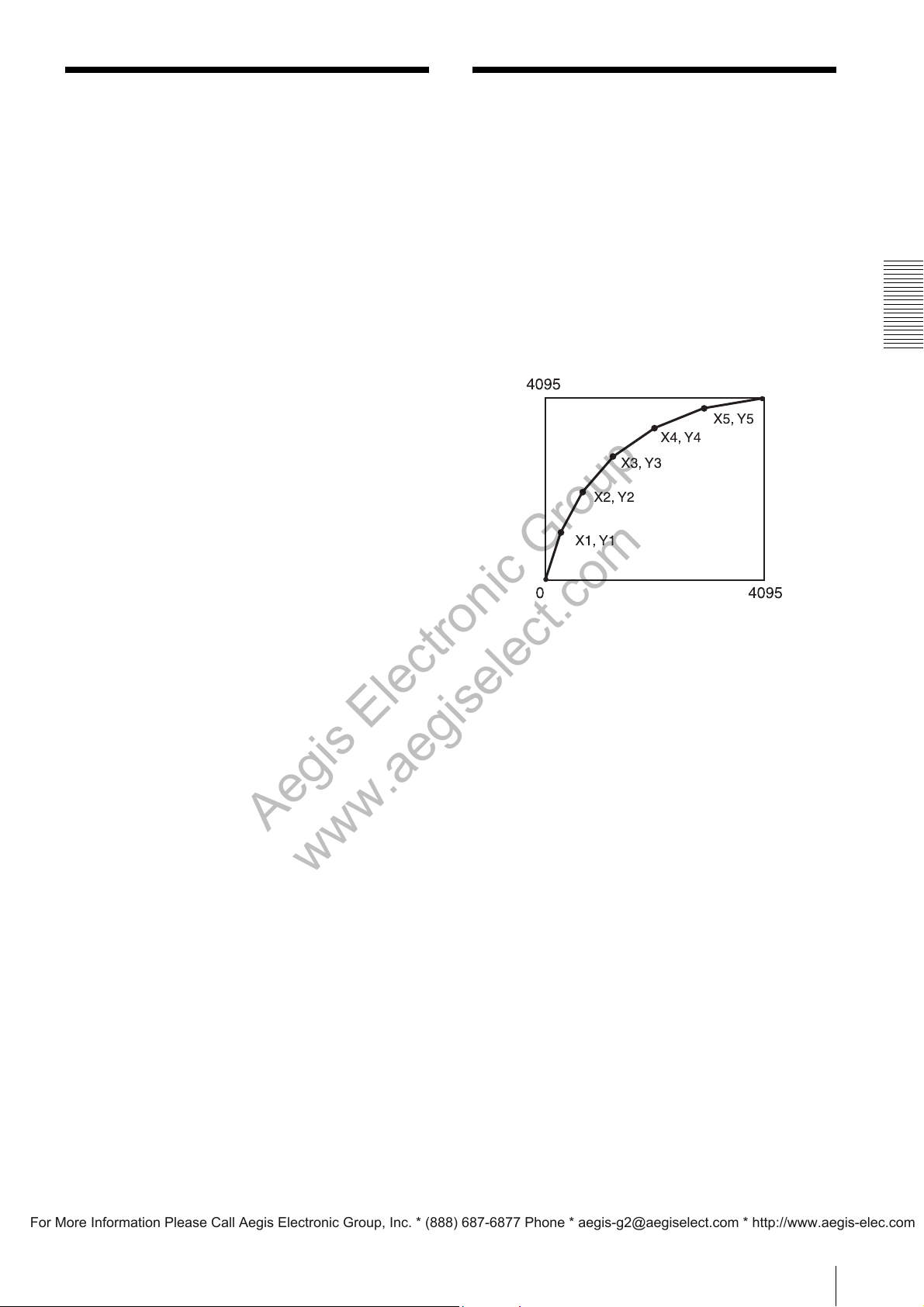
5-Point Linear Interpolated LUT
By specifying the input (X) and output (Y) each for 5
points as desired, you can create an LUT through linear
interpolation between the specified points.
The specified points are sorted by inputs (X), then an
LUT is created by linearly interpolating between (0,0)
and (X1,Y1), ..., then (X5,Y5) and (4095,4095).
Setting parameters:LinearInterpolationIndex = 1
LinearInterpolationInValue = X1
LinearInterpolationOutValue = Y1
:
LinearInterpolationIndex = 5
LinearInterpolationInValue = X5
LinearInterpolationOutValue = Y5
LinearInterpolationBuild = Execute
Functions
19
Page 20
GPIO
Aegis Electronic Group
www.aegiselect.com
For More Information Please Call Aegis Electronic Group, Inc. * (888) 687-6877 Phone * [email protected] * http://www.aegis-elec.com
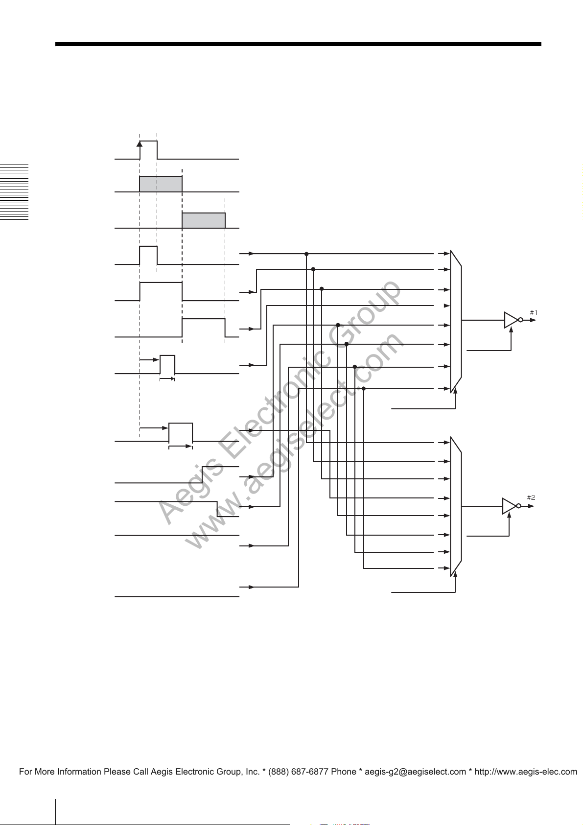
The camera has two GPO ports for outputting various signals, as well as two GPI ports for observing signal levels.
For setting the output signal and polarity for GPO or checking via GPI, first select the port using the Line Selector.
Setting parameter: LineSelector = Line1/Line2/Line5/Line6
Trigger
Exposure
Functions
Sensor ReadOut
Trigger Through
output
Exposure output
Sensor ReadOut
output
Strobe control
output [Line 1]
Strobe control
output [Line 2]
User output [1]
Strobe delay [Line 1]
Strobe width [Line 1]
Strobe delay [Line 2]
Strobe width [Line 2]
Trigger Through output
Exposure output
Sensor ReadOut output
Strobe control output [Line 1]
User output [1]
User output [2]
Tr u e
False
LineSource [Line 1]
Trigger Through output
Exposure output
Sensor Readout output
Strobe control output [Line 2]
Terminal Block
Line Inverter
[Line 1]
Terminal Block
User output [2]
Tr u e
False
User output [1]
User output [2]
Tr u e
False
LineSource [Line 2]
Line Inverter
[Line 2]
20
Page 21
Line Inverter
Aegis Electronic Group
www.aegiselect.com
For More Information Please Call Aegis Electronic Group, Inc. * (888) 687-6877 Phone * [email protected] * http://www.aegis-elec.com
You can inverse the signal to be output to GPO.
Setting parameter: LineInverter[LineSelector] = True/
False
Line Sources
The signals mentioned below can be selected for the
output from the GPO ports.
If the line inverter is set to “False,” all signals are High
Active.
Trigger Through output
The signal supplied to the trigger input connector
selected with “TriggerSource” is output as-is.
Setting parameter: LineSource[LineSelector] =
TriggerSignalThroughOut
Exposure output
For outputting the exposure time of the image sensor.
Setting parameter: LineSource[LineSelector] =
ExposureActive
UserOutputSelector =
UserOutput1/UserOutput2
UserOutputValue[UserOutputSelec
tor] = True/False
True /False
For outputting the True/False setting.
Settting parameter: LineSource = True/False
Line Status
“True” is returned if the input to the selected GPI port is
High, and “False” is returned if it is Low.
Observation parameter: LineStatus[LineSelector] =
True/False
Functions
Sensor ReadOut output
For outputting the status of reading from the image
sensor.
Setting parameter: LineSource[LineSelector] =
SensorReadOutActive
Strobe control outputs
For fine adjustment of strobe control for external devices
connected to the camera by controlling the timing and
width of signal generation.
The strobe delay and width can be set each for the GPO1
and GPO2 ports.
Setting parameters: LineSource[LineSelector] =
StrobeActive
StrobeActiveTime[LineSelector] =
1 to 4000 (us)
StrobeActiveDelay[LineSelector] =
0 to 4000 (us)
Note
When using strobe control output, if the strobe delay or
strobe width exceeds the exposure interval, proper
strobe signals cannot be output. Set the strobe control
output so that the delay and width are within the
exposure time.
User outputs
For outputting the user-specified True/False setting.
The camera provides two user output settings (User
Output 1 and User Output 2) which can be selected each
for GPO1 and GPO2 port.
Setting parameters: LineSource[LineSelector] =
UserOutput1/UserOutput2
21
Page 22
Memory Shot
Aegis Electronic Group
www.aegiselect.com
For More Information Please Call Aegis Electronic Group, Inc. * (888) 687-6877 Phone * [email protected] * http://www.aegis-elec.com
User Set/User Memories
Functions
The camera has the Memory Shot function to store
images in internal frame memory and read them when
required.
When multiple cameras are connected to the host
computer via a single hub, the Memory Shot function
may be useful in cases where simultaneous image
outputs are disabled because of the band restriction of 1
Gbps.
Up to 16 frames can be stored in memory.
Memory Shot mode can be used regardless of the trigger
mode and special trigger mode settings.
Activating Memory Shot mode
Memory Shot mode can be activated.
Captured images are stored in frame memory until a
ReadOut command is issued.
Setting parameter: MemoryShotMode = On
Confirming the number of images stored
in frame memory
You can confirm how many images have been stored.
Observation parameter: MemoryShotNumberOfImages
InMemory
Reading an image
You can send an image stored in the frame memory to
the host PC.
Setting parameter: MemoryShotSingleRead = Execute
Reading multiple images
You can send the specified number of images stored in
frame memory to the host PC.
Setting parameters: MemoryShotNumberOfImages
ToRead= 1 to 16
MemoryShotMultiFrameRead =
Execute
User Set
The camera has the User Set function for storing the
camera settings and loading them when required to
change the camera status accordingly. Up to 16
configurations of settings can be stored. This function
also enables shooting frame by frame with different
configurations of the camera settings by loading the
User Set data in sequence in Bulk Trigger or Sequential
Trigger mode.
When storing data in a User Set, first specify the
destination User Set then execute storage.
Setting parameters: UserSetSelector = UserSet0 to
UserSet15
UserSetSave = Execute
When loading data from a User Set, first specify the
source User Set then execute loading.
Setting parameters: UserSetSelector = UserSet0 to
UserSet15 / Default
UserSetSave = Execute
When you select “Default” for the source, the following
items will return to the factory-set conditions, in
addition to the items stored in the User Set:
• TestImageSelector
• GainAutoAreaWidth
• GainAutoAreaHeight
• GainAutoAreaOffsetX
• GainAutoAreaOffsetY
• AcquisitionMode
• SpecialTriggerMode
• NumberOfMemoryForSpecialTriggerMode
• SpecialTriggerSource
• SpecialTriggerActivation
User Memories
Each User Set provides 64 bytes of nonvolatile readwrite storage for users to store data freely. Stored data
are retained even when the power is turned off.
Note
Frame memory can store 16 images at maximum,
regardless of image size.
Any image captured under the condition that there are
already 16 images in frame memory will be discarded,
and not stored in frame memory.
22
Page 23
Chunk Data
Aegis Electronic Group
www.aegiselect.com
For More Information Please Call Aegis Electronic Group, Inc. * (888) 687-6877 Phone * [email protected] * http://www.aegis-elec.com
The camera supports the chunk data format transferring
images and various types of information on shot images.
The following items are transferred as chunk data:
Essential item
•Image
•OffsetX
•OffsetY
• Width
• Height
• PixelFormat
Optional item
• TriggerCounter
• Temperature
• LineStatusAll
• ExposureTime
• GainAnalog
•UserMemory
• LineOutputStatus
Setting parameters:ChunkModeActive = True/False
ChunkSelector = TriggerCounter/
Temperature/
LineStatusAll/
ExposureTime/
GainAnalog/
UserMemory/
LineOutputStatus
ChunkEnable[ChunkSelector] =
True/False
Note
When the chunk mode is activated, the format of
transferred packets differs from normal image transfer.
This will prevent applications that do not support the
chunk data format from obtaining images.
Functions
23
Page 24
Control Operations
Aegis Electronic Group
www.aegiselect.com
For More Information Please Call Aegis Electronic Group, Inc. * (888) 687-6877 Phone * [email protected] * http://www.aegis-elec.com
Camera Control Registers
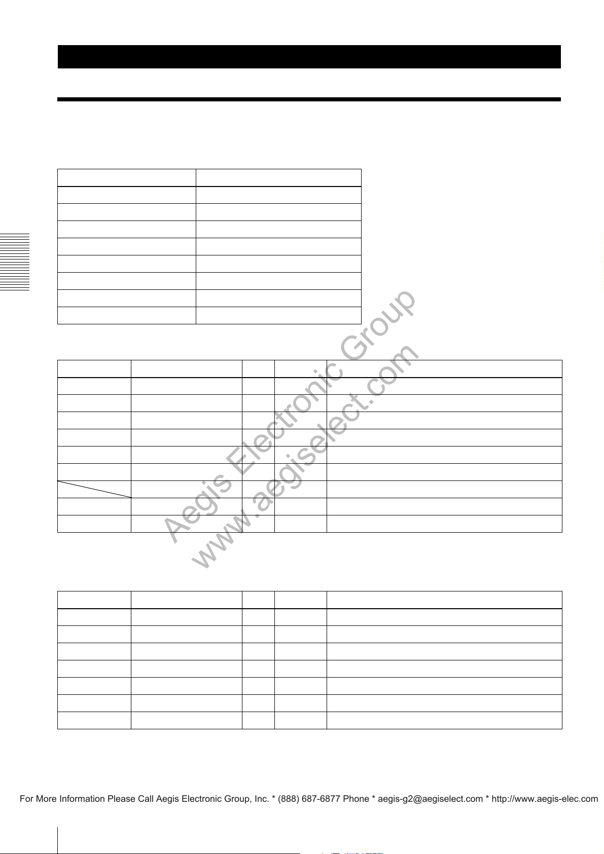
There is a diagonal line in the Address column of registers for which there is a definition for XML only and there is no
address definition.
Address Register
0x00000000 Base Address
0x00000000 - 0x00009FFC GigE Vision Bootstrap
0xA0000000 Camera Base Address
0xA0000000 - 0xA00020BC Camera Control
0xA00020C0 - 0xA00020FC User Memory
0xA0003000 - 0xA00030FC Camera Control
Control Operations
0xA0007000 - 0xA00070FC Camera Control Inq
0xA0010000 - 0xA0013FFC LUT Control
DeviceControl
Address Name Type Data Description
0x00000068 DeviceVendorName R/O
0x00000088 DeviceModelName R/O
0x000000A8 DeviceVersion R/O
0x000000D8 DeviceManufacturerInfo R/O
0x000000D8 DeviceID R/O
0x000000E8 DeviceUserID R/W
DeviceScanType R/O – Displays the scan type.
0xA0000010 DeviceReset W/O 1 Executes a device reset.
0xA0000014 DeviceTemperature R/O Displays the device temperature (°C).
1)
1)
1)
1)
1)
1)
Displays the vendor name.
Displays the model name.
Displays the version.
Displays the manufacturer information.
Displays the serial number.
Sets the user ID.
1) This value is unique to the model.
ImageFormatControl
Address Name Type Data Description
0xA0000124 SensorTaps R/W 2,4 Sets the number of Taps to be read from the image sensor.
0xA0000100 Width R/W
0xA0000104 Height R/W
0xA0000108 OffsetX R/W
0xA000010C OffsetY R/W
0xA0000118 BinningHorizontal
0xA0000114 BinningVertical
2)
2)
R/W 1,2 Sets Horizontal Binning.
R/W 1,2 Sets Vertical Binning.
1)
1)
1)
1)
Sets the number of horizontal pixels (H).
Sets the number of vertical lines (V).
Sets the offset of the number of horizontal pixels (H).
Sets the offset of the number of vertical lines (V).
24
Page 25
Address Name Type Data Description
Aegis Electronic Group
www.aegiselect.com
For More Information Please Call Aegis Electronic Group, Inc. * (888) 687-6877 Phone * [email protected] * http://www.aegis-elec.com
0xA0000110 PixelFormat R/W
PixelSize R/O 8 Configures with 8-bit pixels (Bpp8).
PixelColorFilter R/O 0 Displays the color filter (no).
0xA0000130 TestImageSelector R/W 0 Sets the test image to OFF.
0xA0000134 GainAutoAreaHighlight R/W 0 Sets the auto gain detection frame to OFF.
0xA0000138 GainAutoAreaWidth R/W 1 - 100 Sets the auto gain detection frame (H).
0x01080001
0x010C0004
0x010C0006
0x01080009
0x010C0027
0x010C002B
10 Configures with 10-bit pixels (Bpp10).
12 Configures with 12-bit pixels (Bpp12).
1 Displays the color filter (RG).
1 Sets the test image to gray scale chart.
2 Sets the test image to color chart.
1 Sets the auto gain detection frame to ON.
Sets to 8-bit black and white (Mono8).
Sets to 10-bit black and white (Mono10 Packed).
Sets to 12-bit black and white (Mono12 Packed).
Sets to bayer 8-bit (BayerRG8).
Sets to bayer 10-bit (BayerRG10Packed).
Sets to bayer 12-bit (BayerRG12Packed).
2)
3)
2)
3)
2)
2)
3)
3)
Control Operations
0xA000013C GainAutoAreaHeight R/W 1 - 100 Sets the auto gain detection frame (V).
0xA0000140 GainAutoAreaOffsetX R/W 0 - 99 Sets the offset of the auto gain detection frame (H).
0xA0000144 GainAutoAreaOffsetY R/W 0 - 99 Sets the offset of the auto gain detection frame (V).
0xA0000154 BalanceWhiteAutoAreaHi
0xA0000158 BalanceWhiteAutoAreaWi
0xA000015C BalanceWhiteAutoAreaHei
0xA0000160 BalanceWhiteAutoAreaOff
0xA0000164 BalanceWhiteAutoAreaOff
ghlight
3)
dth
3)
ght
3)
setX
3)
setY
3)
R/W 0 Sets the white balance detection frame to OFF.
1 Sets the white balance detection frame to ON.
R/W 0 - 100 Sets the white balance detection frame (H).
R/W 0 - 100 Sets the white balance detection frame (V).
R/W 0 - 100 Sets the offset of the white balance detection frame (H).
R/W 0 - 100 Sets the offset of the white balance detection frame (V).
1)This value is unique to the model.
2)XCG-H280E only
3)XCG-H280CR only
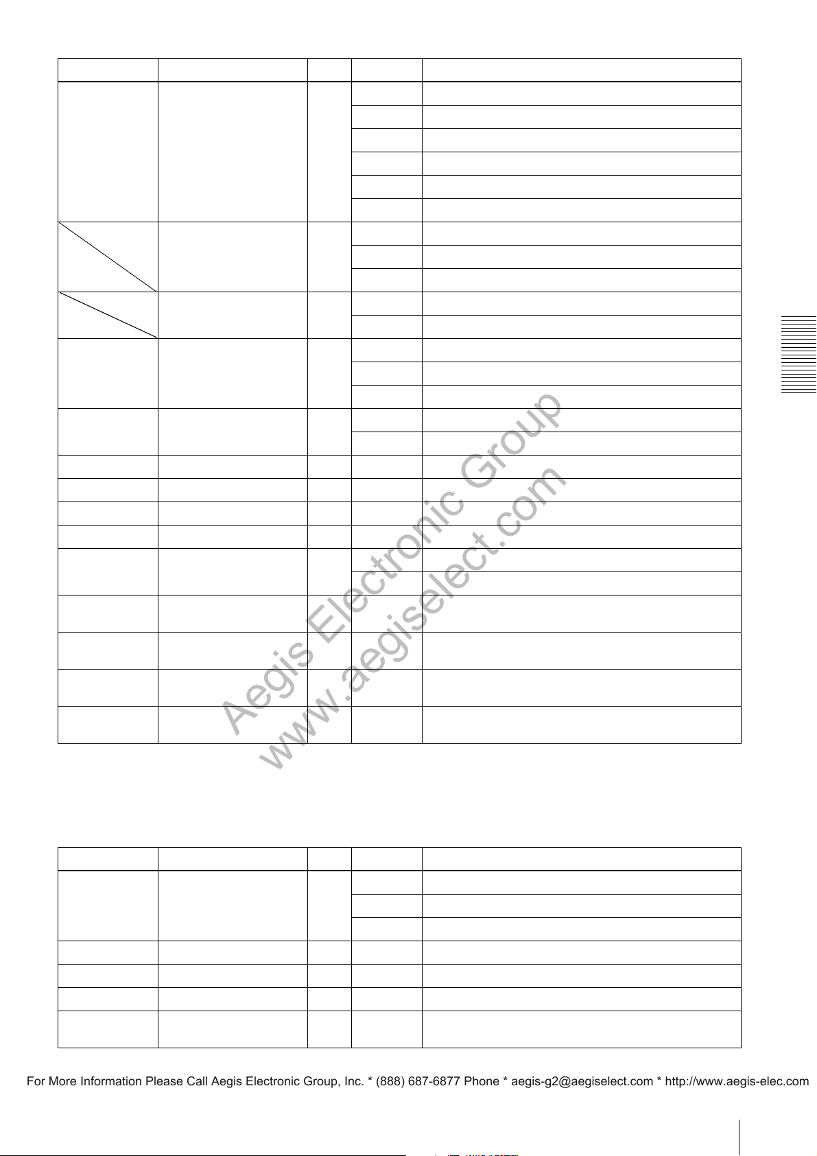
AcquisitionControl
Address Name Type Data Description
0xA0000200 AcquisitionMode R/W 1 Sets free run (Continuous).
2 Sets multi frames (MultiFrame).
3 Sets a single frame (SingleFrame).
0xA0000210 AcquisitionStart W/O 1 Executes start of image transfer.
0xA0000214 AcquisitionStop W/O 0 Executes stop of image transfer.
0xA0000204 AcquisitionFrameCount R/W 2 - 255 Sets the frame count of multi frames.
0xA0000220 AcquisitionFrameRate R/W 62500 -
180000000
Sets the frame rate. [fps]
1)
25
Page 26
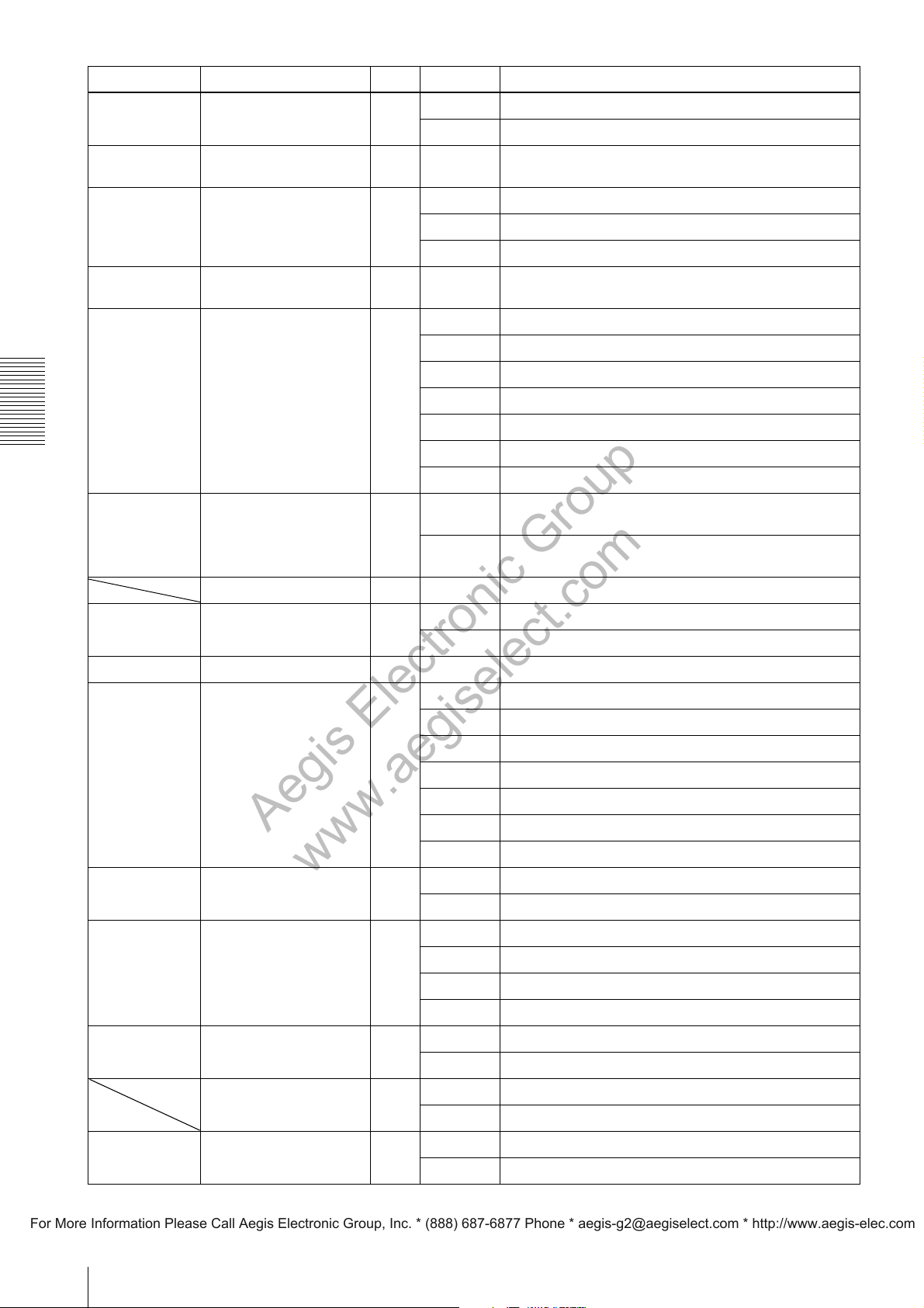
Address Name Type Data Description
Aegis Electronic Group
www.aegiselect.com
For More Information Please Call Aegis Electronic Group, Inc. * (888) 687-6877 Phone * [email protected] * http://www.aegis-elec.com
0xA0000224 AcquisitionFrameRateAuto R/W 0 Sets the auto frame rate to OFF.
1 Sets the auto frame rate to ON.
0xA0000228 AcquisitionFrameRateActualR/O – Displays the frame rate. [fps]
1)
0xA0000300 SpecialTriggerMode
0xA0000304 NumberOfMemoryForSpe
cialTriggerMode
0xA00002F0 SpecialTriggerSource R/W 0 Sets the trigger source for special trigger to Line3.
Control Operations
0xA00002F4 SpecialTriggerActivation R/W 0 Sets the trigger of the special trigger to the edge of negative
TriggerSelector R/O – Displays the trigger type.
0xA0002044 TriggerMode R/W 0 Sets the trigger to OFF.
0xA00002F8 TriggerSoftware W/O 1 Executes the software trigger.
2)
R/W 0 Sets the special trigger to OFF.
1 Sets the special trigger to bulk trigger mode.
2 Sets the special trigger to sequential trigger mode.
R/W 1 - 16 Sets the frame count of the special trigger.
1 Sets the trigger source for special trigger to Line4.
2 Sets the trigger source for special trigger to Line3 or Line4.
3 Sets the trigger sources for special trigger to Line3 and Line4.
4 Sets the trigger source for special trigger to the software.
5 Sets the trigger source for special trigger to Line5.
6 Sets the trigger source for special trigger to Line6.
polarity.
1 Sets the trigger of the special trigger to the edge of positive
polarity.
1 Sets the trigger to ON.
0xA0002098 TriggerSource R/W 0 Sets the trigger source to Line3.
1 Sets the trigger source to Line4.
2 Sets the trigger source to Line3 or Line4.
3 Sets the trigger sources to Line3 and Line4.
4 Sets the trigger source to the software.
5 Sets the trigger source to Line5.
6 Sets the trigger source to Line6.
0xA0002050 TriggerInhibit R/W 0 Sets trigger inhibit to OFF.
1 Sets trigger inhibit to ON.
0xA0002048 TriggerActivation R/W 6 Sets the trigger to the edge of positive polarity.
4 Sets the trigger to the edge of negative polarity.
7 Sets the trigger to the level of positive polarity.
5 Sets the trigger to the level of negative polarity.
0xA00020BC TriggerActivation R/W 0 Sets the trigger to negative polarity.
1 Sets the trigger to positive polarity.
TriggerOverlap R/O 0 Indicates that trigger overlap is not allowed.
1 Indicates that trigger overlap is allowed during sensor reading.
0xA0002054 TriggerShift R/W 0 Sets trigger shift to OFF.
1 Sets trigger shift to ON.
26
Page 27
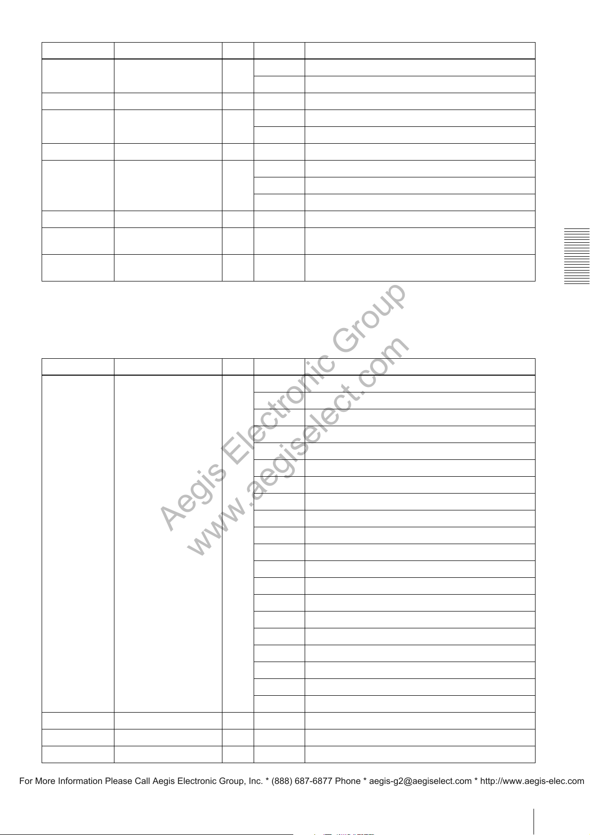
Address Name Type Data Description
Aegis Electronic Group
www.aegiselect.com
For More Information Please Call Aegis Electronic Group, Inc. * (888) 687-6877 Phone * [email protected] * http://www.aegis-elec.com
0xA00020B4 TriggerControl R/W 0 Sets trigger width mode to “Exact Exposure Time” operation.
1 Sets trigger width mode to “Minimum Delay” operation.
0xA0002058 TriggerDelay R/W
0xA00020B8 ExposureMode R/W 0 Sets the exposure time by ExposureTime.
0xA0002040 ExposureTime R/W
0xA0002140 ExposureAuto R/W 0 Sets the auto exposure to OFF.
0xA0002144 ExposureAutoSpeed R/W 1 - 256 Sets the response speed of the auto exposure.
0xA0002148 ExposureAutoLowerLimit R/W
0xA000214C ExposureAutoUpperLimit R/W
0 - 4000000
1 Sets the exposure time by the trigger signal width.
10 - 2000000
1 Sets the auto exposure to Once.
2 Sets the auto exposure to Continuous.
10 - 2000000
10 - 2000000
Sets the trigger delay. [us]
Sets the exposure time. [us]
Sets the lower limit of the exposure time controlled by the
auto exposure. [us]
Sets the upper limit of the exposure time controlled by the
auto exposure. [us]
1) For reading/writing data from/to the register, use integers of 1,000,000 times the fps value.
When fps is 32, use 32,000,000.
2) The settings of SpecialTriggerMode are deleted and unsaved when the power is turned OFF.
AnalogControl
Address Name Type Data Description
0xA00030B0 GainSelector
1)
R/W 16 Sets the gain selector to AnalogAll.
17 Sets the gain selector to AnalogTap1.
Control Operations
18 Sets the gain selector to AnalogTap2.
19 Sets the gain selector to AnalogTap3.
20 Sets the gain selector to AnalogTap4.
48 Sets the gain selector to DigitalRedAll.
49 Sets the gain selector to DigitalRedTap1.
50 Sets the gain selector to DigitalRedTap2.
51 Sets the gain selector to DigitalRedTap3.
52 Sets the gain selector to DigitalRedTap4.
64 Sets the gain selector to DigitalGreenAll.
65 Sets the gain selector to DigitalGreenTap1.
66 Sets the gain selector to DigitalGreenTap2.
67 Sets the gain selector to DigitalGreenTap3.
68 Sets the gain selector to DigitalGreenTap4.
96 Sets the gain selector to DigitalRedAll.
97 Sets the gain selector to DigitalBlueTap1.
98 Sets the gain selector to DigitalBlueTap2.
99 Sets the gain selector to DigitalBlueTap3.
100 Sets the gain selector to DigitalBlueTap4.
0xA00030A0 Gain[AnalogAll] R/W 0 - 502 Sets the gain (AnalogAll).
0xA0002010 Gain[AnalogTap1] R/W 0 - 502 Sets the gain (AnalogTap1).
0xA0002014 Gain[AnalogTap2] R/W 0 - 502 Sets the gain (AnalogTap2).
2)
2)
2)
2)
2)
2)
2)
2)
2)
2)
3)
3)
3)
27
Page 28
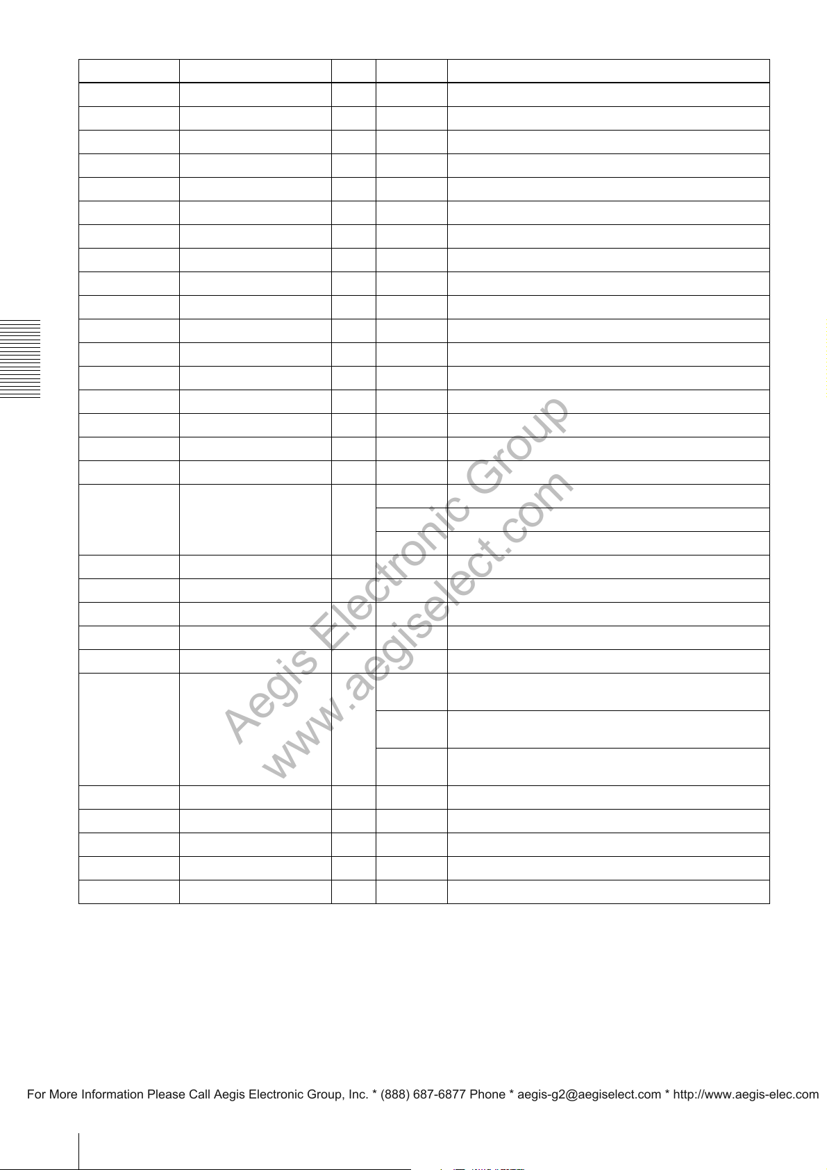
Address Name Type Data Description
Aegis Electronic Group
www.aegiselect.com
For More Information Please Call Aegis Electronic Group, Inc. * (888) 687-6877 Phone * [email protected] * http://www.aegis-elec.com
0xA0003088 Gain[AnalogTap3] R/W 0 - 502 Sets the gain (AnalogTap3).
0xA000308C Gain[AnalogTap4] R/W 0 - 502 Sets the gain (AnalogTap4).
0xA0003000 Gain[DigitalRedAll] R/W 128 - 2047 Sets the gain (DigitalRedAll).2)
0xA0003040 Gain[DigitalRedTap1] R/W 128 - 2047 Sets the gain (DigitalRedTap1).2)
0xA0003004 Gain[DigitalRedTap2] R/W 128 - 2047 Sets the gain (DigitalRedTap2).2)
0xA0003048 Gain[DigitalRedTap3] R/W 128 - 2047 Sets the gain (DigitalRedTap3).2)
0xA000304C Gain[DigitalRedTap4] R/W 128 - 2047 Sets the gain (DigitalRedTap4).2)
0xA0003008 Gain[DigitalGreenAll] R/W 128 - 2047 Sets the gain (DigitalGreenAll).2)
0xA0003050 Gain[DigitalGreenTap1] R/W 128 - 2047 Sets the gain (DigitalGreenTap1).2)
0xA000300C Gain[DigitalGreenTap2] R/W 128 - 2047 Sets the gain (DigitalGreenTap2).2)
0xA0003058 Gain[DigitalGreenTap3] R/W 128 - 2047 Sets the gain (DigitalGreenTap3).2)
0xA000305C Gain[DigitalGreenTap4] R/W 128 - 2047 Sets the gain (DigitalGreenTap4).2)
0xA0003018 Gain[DigitalBlueAll] R/W 128 - 2047 Sets the gain (DigitalBlueAll).2)
Control Operations
0xA0003070 Gain[DigitalBlueTap1] R/W 128 - 2047 Sets the gain (DigitalBlueTap1).2)
0xA000301C Gain[DigitalBlueTap2] R/W 128 - 2047 Sets the gain (DigitalBlueTap2).2)
0xA0003078 Gain[DigitalBlueTap3] R/W 128 - 2047 Sets the gain (DigitalBlueTap3).2)
0xA000307C Gain[DigitalBlueTap4] R/W 128 - 2047 Sets the gain (DigitalBlueTap4).2)
3)
3)
4)
4)
4)
4)
4)
4)
4)
4)
4)
4)
4)
4)
4)
4)
4)
0xA000201C GainAuto R/W 0 Sets the auto gain to OFF.
1 Sets the auto gain to Once.
2 Sets the auto gain to Continuous.
0xA0002020 GainAutoLevel R/W 0 - 16383 Sets the auto gain level.
0xA0002154 GainAutoSpeed R/W 1 - 256 Sets the response speed of auto gain.
0xA0002158 GainAutoLowerLimit R/W 0 - 502 Sets the lower limit of gain controlled by auto gain.
0xA000215C GainAutoUpperLimit R/W 0 - 502 Sets the upper limit of gain controlled by auto gain.
0xA0002038 BlackLevel R/W 0 - 2047 Sets the pedestal level.
0xA0002018 BlackLevelAutoBalance R/W 0 Set the automatic black level adjustment between Taps to
1 Set the automatic black level adjustment between Taps to
2 Set the automatic black level adjustment between Taps to
0xA00030B4 BlackLevelAdjustSelector R/W 1 - 4 Selects the Tap for black level adjustment.
0xA0003090 BlackLevelAdjust[Tap1] R/W -255 - 255 Sets the black level adjustment to Tap1.
0xA0003094 BlackLevelAdjust[Tap2] R/W -255 - 255 Sets the black level adjustment to Tap2.
0xA0003098 BlackLevelAdjust[Tap3] R/W -255 - 255 Sets the black level adjustment to Tap3.
0xA000309C BlackLevelAdjust[Tap4] R/W -255 - 255 Sets the black level adjustment to Tap4.
OFF.
Once.
Continuous.
1) The settings of GainSelector and BlackLevelSelector, are deleted and unsaved when the power is turned OFF.
2) XCG-H280CR only
3) The value of 0.0359×data will be set for the gain (dB).
4) 20×log10 (Data/256) will be set for the gain (dB).
28
Page 29
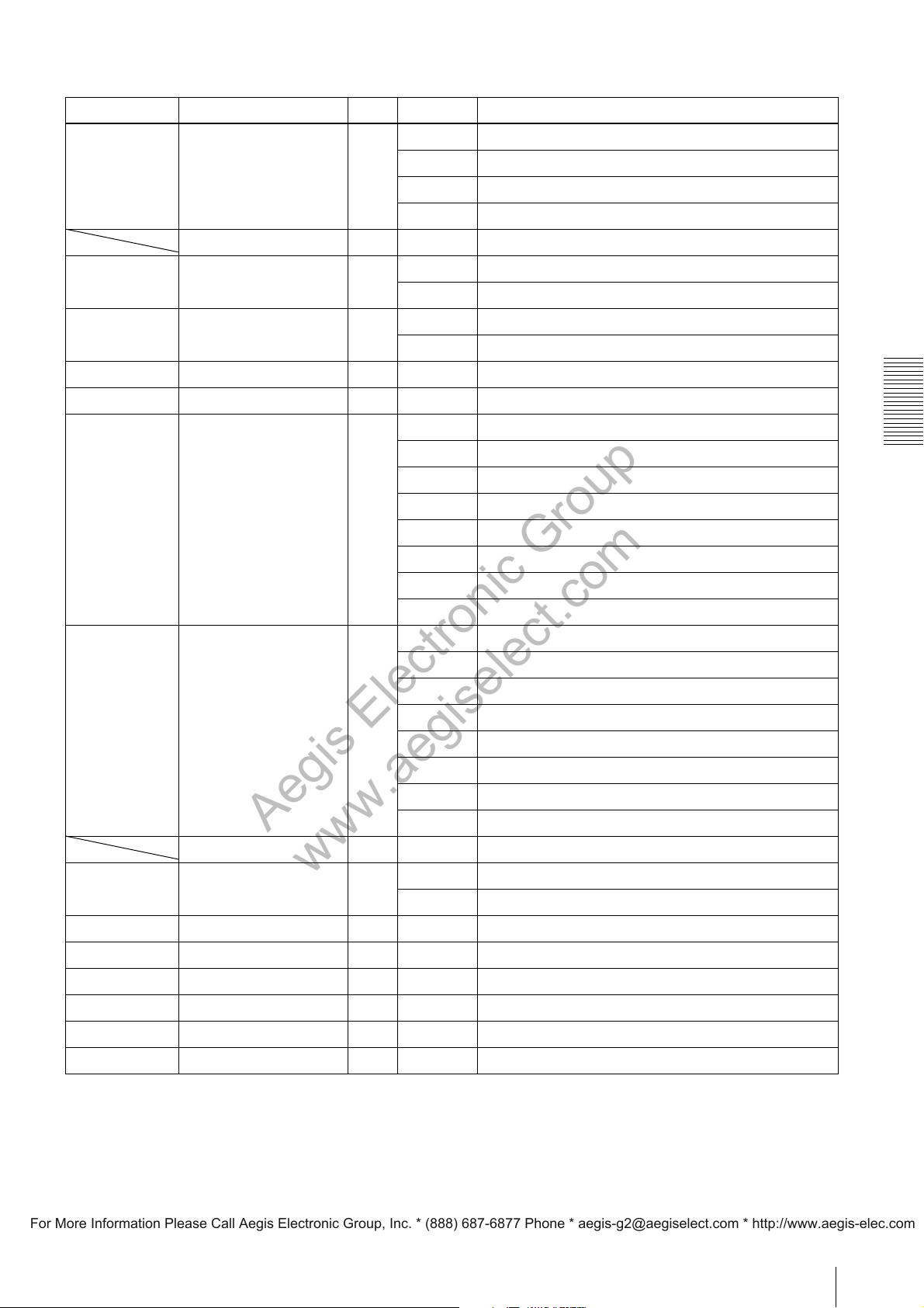
DigitallOControl
Aegis Electronic Group
www.aegiselect.com
For More Information Please Call Aegis Electronic Group, Inc. * (888) 687-6877 Phone * [email protected] * http://www.aegis-elec.com
Address Name Type Data Description
0xA0000354 LineSelector
LineMode R/O – Displays the input/output of GPI and GPO.
0xA00020A8 LineInverter[Line1] R/W 0 Sets GPO1 inversion to OFF.
0xA00020AC LineInverter[Line2] R/W 0 Sets GPO2 inversion to OFF.
0xA0000400 bit0 LineStatus[Line5] R/O – Displays the GPI1 signal.
0xA0000400 bit1 LineStatus[Line6] R/O – Displays the GPI2 signal.
0xA000206C LineSource[Line1] R/W 0 Selects the Exposure signal.
1)
R/W 0 Selects GPO1 (Line1).
1 Selects GPO2 (Line2).
2 Selects GPI1 (Line5).
3 Selects GPI2 (Line6).
1 Sets GPO1 inversion to ON.
1 Sets GPO2 inversion to ON.
1 Selects the Strobe1 signal.
2 Selects UserOutput[1].
3 Selects UserOutput[2].
4 Selects the SensorReadOut signal.
5 Selects the TriggerSignal.
6 Selects True.
7 Selects False.
0xA0002080 LineSource[Line2] R/W 0 Selects the Exposure signal.
1 Selects the Strobe2 signal.
2 Selects UserOutput[1].
3 Selects UserOutput[2].
4 Selects the SensorReadOut signal.
5 Selects the TriggerSignal.
6 Selects True.
7 Selects False.
LineFormat R/O – Displays the signal format of GPI and GPO.
0xA0000358 UserOutputSelector
0xA0002090 bit0 UserOutputValue[1] R/W 0 - 1 Specifies the User Output[1] signal.
1)
R/W 0 Selects UserOutput0.
1 Selects UserOutput1.
Control Operations
0xA0002090 bit1 UserOutputValue[2] R/W 0 - 1 Specifies the User Output[2] signal.
0xA0002078 StrobeActiveTime[Line1] R/W 1 - 4000 Specifies the pulse width of the Strobe1 signal. [us]
0xA000208C StrobeActiveTime[Line2] R/W 1 - 4000 Specifies the pulse width of the Strobe2 signal. [us]
0xA0002074 StrobeActiveDelay[Line1] R/W 0 - 4000 Specifies the delay of the Strobe1 signal. [us]
0xA0002088 StrobeActiveDelay[Line2] R/W 0 - 4000 Specifies the delay of the Strobe2 signal. [us]
1) The settings of LineSelector, and UserOutputSelector are deleted and unsaved when the power is turned OFF.
29
Page 30
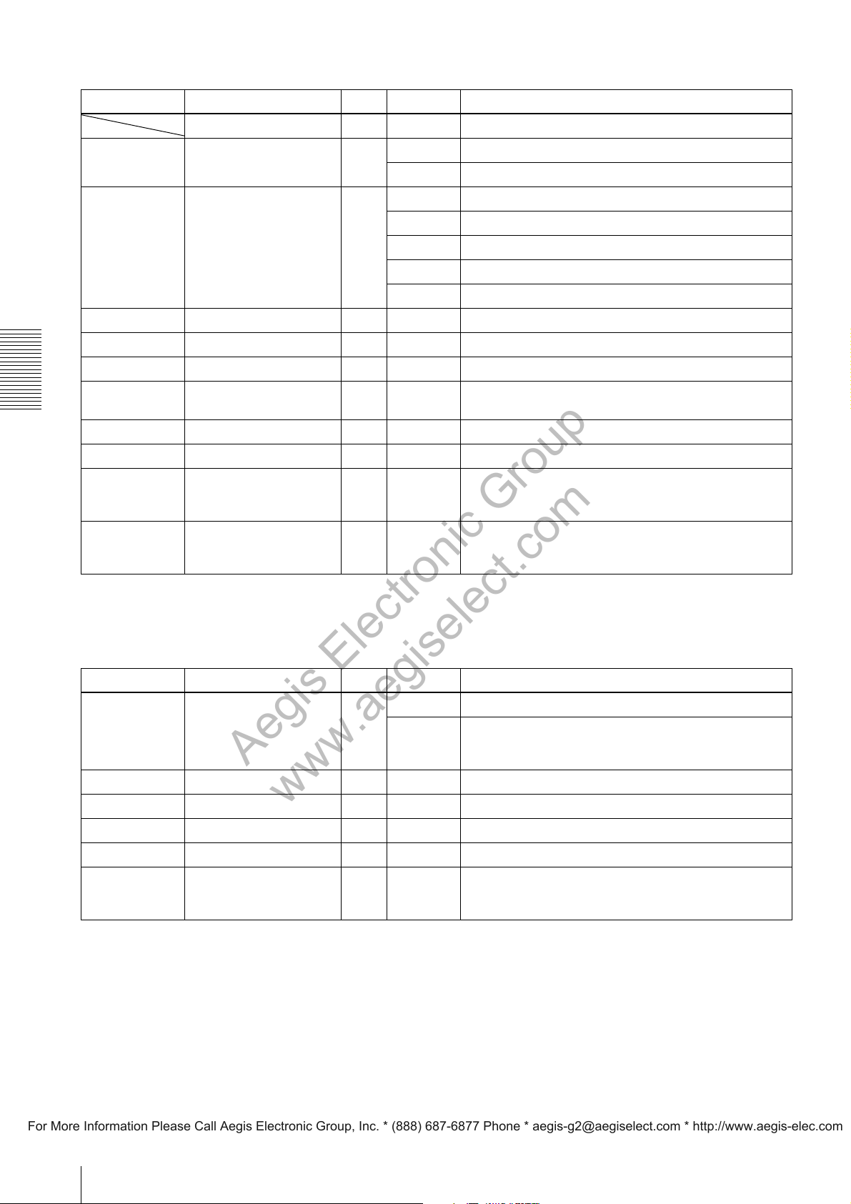
LUTControl
Aegis Electronic Group
www.aegiselect.com
For More Information Please Call Aegis Electronic Group, Inc. * (888) 687-6877 Phone * [email protected] * http://www.aegis-elec.com
Address Name Type Data Description
LUTSelector R/O – Displays the LUT control.
0xA0002060 LUTEnable R/W 0 Disables LUT.
1 Enables LUT.
0xA000205C LUTFormat R/W 0 Sets linear.
1 Sets reverse.
2 Sets binarization.
3 Sets the 5-point linear interpolation LUT.
4 Sets the user setting
0xA0002064 BinarizationThreshold R/W 0 - 4095 Sets the threshold value for binalization.
0xA0000340 LinearInterpolationIndex R/W 1 - 5 Selects the point for setting the linear interpolation LUT.
0xA0000344 LinearInterpolationInValue R/W 0 - 4095 Sets the input value of the linear interpolation LUT.
0xA0000348 LinearInterpolationOutValueR/W 0 - 4095 Sets the output value of the linear interpolation LUT.
1)
.
Control Operations
0xA000034C LinearInterpolationBuild R/W 1 Builds the table of the linear interpolation LUT.
0xA0000350 LUTIndex R/W 0 - 4095 Sets Index of LUT.
0xA0010000
–
0xA0013FFC
0xA0010000
–
0xA0013FFC
LUTValue R/W 0 - 4095 Sets Value of LUT.
LUTValueAll R/W 0 - 4095 Sets LUT with Streaming.
1) Set the user setting value with LUTIndex, LUTValue, and LUTValueAll.
2) The setting of LUTIndex is deleted and unsaved when the power is turned OFF.
UserSetControl
Address Name Type Data Description
0xA0001000 UserSetSelector R/W 16 Sets UserSet to the default value.
0
–
15
0xA0001008 UserSetLoad R/W 3 Loads the setting value of UserSet
0xA0001004 UserSetSave R/W 3 Saves the setting value of UserSet
0xA000100C UserSetDefaultSelector R/W 0 - 16 Selects UserSet to be applied upon startup.
0xA0000350 UserMemoryIndex
3)
R/W 0 - 15 Sets Index of UserMemory.
Sets UserSet0
–
Sets UserSet15
1)
.
1)
.
2)
.
2)
.
0xA00020C0
–
0xA00020FC
UserMemoryValue R/W – Sets Value of UserMemory.
1) UserSet0 - 15 can be directly set with a specific address. For details, see “User Set Registers” (page 33).
2) UserSet that was selected with UserSetSelector is applicable.
3) UserMemoryIndex is deleted and unsaved when the power is turned OFF.
30
Page 31
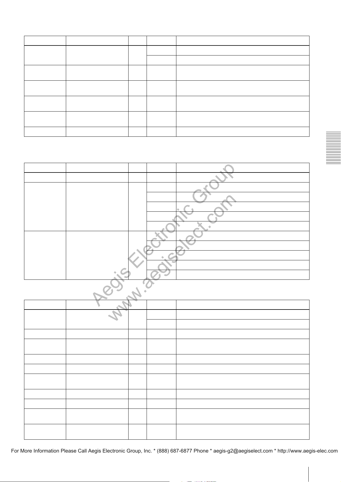
MemoryShotControl
Aegis Electronic Group
www.aegiselect.com
For More Information Please Call Aegis Electronic Group, Inc. * (888) 687-6877 Phone * [email protected] * http://www.aegis-elec.com
Address Name Type Data Description
0xA0002200 MemoryShotMode R/W 0 Sets Memory Shot mode to OFF.
1 Sets Memory Shot mode to ON.
0xA0002208 MemoryShotNumberOfMe
mory
0xA0002204 MemoryShotNumberOfIm
agesInMemory
0xA000220C MemoryShotNumberOfIm
agesToRead
0xA0002210 MemoryShotMultiFrameR
ead
0xA0002214 MemoryShotSingleRead W/O 1 Executes single-image reading.
R/O 16 Displays the number of memory channels used for Memory
Shot.
R/O – Displays the number of images stored in memory at present.
R/W 1 - 16 Specifies the number of images for multiple-image reading.
W/O 1 Executes multiple-image reading.
TransportLayerControl
The registers 0x00000000 to 0x00009FFF conform to the Bootstrap register of GigE Vision.
Address Name Type Data Description
0x0000A000 PayloadSize R/O – Displays the payload size.
0x0000A020 GevIPConfigurationStatus R/O 0 IPConfiguration is configured with None.
1 IPConfiguration is configured with PersistentIP.
2 IPConfiguration is configured with DHCP.
3 IPConfiguration is configured with LLA.
4 IPConfiguration is configured with ForceIP.
0x0000A030 GevTimestampResetSignal
Selector
R/W 0 Disables selection of the time stamp reset signal.
1 Resets the time stamp at the falling edge of GPI1.
2 Resets the time stamp at the falling edge of GPI2.
5 Resets the time stamp at the rising edge of GPI1.
10 Resets the time stamp at the rising edge of GPI2.
ChunkDataControl
Address Name Type Data Description
0x0000A100 ChunkModeActive R/W 0 Sets Chunk mode to OFF.
1 Sets Chunk mode to ON.
0x0000A104 ChunkSelector R/W Selects items to be added to the chunk data..
Control Operations
0x0000A108 bit0 ChunkTriggerCounterEnableR/W 0 - 1 Sets to add the trigger counter to the chunk data.
0x0000A108 bit1 ChunkTemperatureEnable R/W 0 - 1 Sets to add the temperature [°C] to the chunk data.
0x0000A108 bit2 ChunkLineStatusAllEnable R/W 0 - 1 Sets to add GPI signal to the chunk data.
0x0000A108 bit3 ChunkExposureTimeEnableR/W 0 - 1 Sets to add the exposure time to the chunk data.
0x0000A108 bit4 ChunkGainAnalogEnable R/W 0 - 1 Sets to add the gain to the chunk data.
0x0000A108 bit5 ChunkUserMemoryEnable R/W 0 - 1 Sets to add the user memory to the chunk data.
0x0000A108 bit6 ChunkLineOutputStatusEn
0x0000A108
bit31
able
ChunkImageEnable R/O 1 Indicates to add images to the chunk data.
R/W 0 - 1 Sets to add GPO signal to the chunk data.
31
Page 32
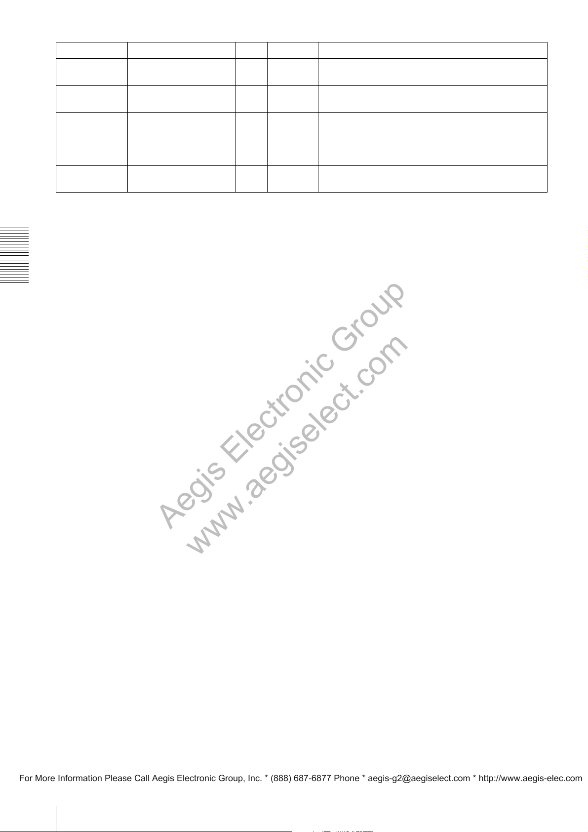
Address Name Type Data Description
Aegis Electronic Group
www.aegiselect.com
For More Information Please Call Aegis Electronic Group, Inc. * (888) 687-6877 Phone * [email protected] * http://www.aegis-elec.com
0x0000A108
bit30
0x0000A108
bit29
0x0000A108
bit28
0x0000A108
bit27
0x0000A108
bit26
Control Operations
ChunkOffsetXEnable R/O 1 Indicates to add the number of holizontal pixels to the chunk
data.
ChunkOffsetYEnable R/O 1 Indicates to add the number of vertical lines to the chunk data.
ChunkWidthEnable R/O 1 Indicates to add the offset of the number of holizontal pixels
to the chunk data.
ChunkHeightEnable R/O 1 Indicates to add the offset of the number of vertical lines to
the chunk data.
ChunkPixelFormatEnable R/O 1 Indicates to add the pixel format to the chunk data.
32
Page 33
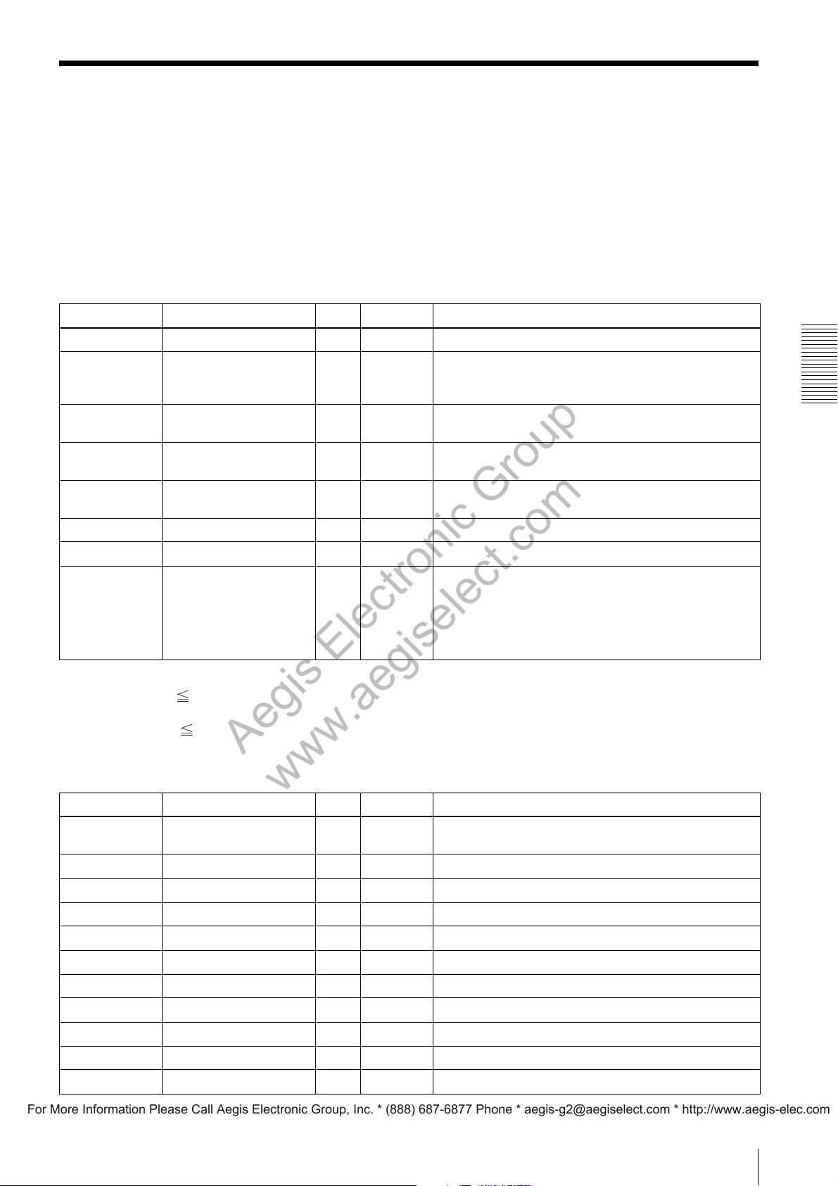
User Set Registers
Aegis Electronic Group
www.aegiselect.com
For More Information Please Call Aegis Electronic Group, Inc. * (888) 687-6877 Phone * [email protected] * http://www.aegis-elec.com
User Set registers enable storing and confirming of settings by directing at UserSet0 to UserSet15.
The addresses of the User Set registers are configured as follows:
0xA000XYZZ
X: Indicates the category.
Y: Indicates the User Set number.
Y=0 means User Set 0, Y=1 means User Set 1, Y=A means User Set 10, and Y=F means User Set 15.
ZZ: Indicates the setting item.
ImageFormatControl (UserSet0 to UserSet15)
Address Name Type Data Description
0xA0005Y24 SensorTaps R/W 2,4 Sets the number of Taps to be read from the image sensor.
0xA0005Y00 Width R/W WidthMin
0xA0005Y04 Height R/W
0xA0005Y08 OffsetX R/W
0xA0005Y0C OffsetY R/W
0xA0005Y18 BinningHorizontal R/W 1,2 Sets Horizontal Binning.
0xA0005Y14 BinningVertical R/W 1,2 Sets Vertical Binning.
0xA0005Y10 PixelFormat R/W
-
WidthMax
HeightMin HeightMax
0 -
WidthMax
0 -
HeightMax
0x01080001
0x010C0004
0x010C0006
0x01080009
0x010C0027
0x010C002B
Sets the number of horizontal pixels (H).
1)
Sets the number of vertical lines (V).
2)
Sets the offset of the number of horizontal pixels (H).
1)
Sets the offset of the number of vertical lines (V).
2)
Sets the pixel format.
1) Observe the following condition when setting:
Width + OffsetX WidthMax
2) Observe the following condition when setting:
Height + OffsetY HeightMax
AcquisitionControl (UserSet0 to UserSet15)
Control Operations
Address Name Type Data Description
0xA0006Y00 AcquisitionFrameRate R/W
0xA0006Y04 AcquisitionFrameRateAuto R/W 0, 1 Sets the auto frame rate.
0xA0008Y44 TriggerMode R/W 0, 1 Sets the trigger.
0xA0008Y98 TriggerSource R/W 0, 1 Sets the trigger source.
0xA0008Y50 TriggerInhibit R/W 0, 1 Sets the trigger inhibit.
0xA0008YBC TriggerActivation R/W 0, 1 Sets the trigger polarity.
0xA0008Y54 TriggerShift R/W 0, 1 Sets the trigger shift.
0xA0008Y58 TriggerDelay R/W
0xA0008YB8 ExposureMode R/W 0,1 Sets Exposure mode.
0xA0008Y40 ExposureTime R/W
0xA0009YB0 ExposureAuto R/W 0, 1, 2 Sets the auto exposure.
62500 -
180000000
0 - 4000000
10 - 2000000
Sets the frame rate. [fps]
Sets the trigger delay. [us]
Sets the exposure time. [us]
33
Page 34
Address Name Type Data Description
Aegis Electronic Group
www.aegiselect.com
For More Information Please Call Aegis Electronic Group, Inc. * (888) 687-6877 Phone * [email protected] * http://www.aegis-elec.com
0xA0009YB4 ExposureAutoSpeed R/W 1 - 256 Sets the response speed of auto exposure.
0xA0009YB8 ExposureAutoLowerLimit R/W
0xA0009YBC ExposureAutoUpperLimit R/W
10 - 2000000
10 - 2000000
Sets the lower limit of the exposure time controlled by auto
exposure. [us]
Sets the upper limit of the exposure time controlled by auto
exposure. [us]
AnalogControl (UserSet0 to UserSet15)
Address Name Type Data Description
0xA0008Y10 Gain[AnalogTap1] R/W 0 - 502 Sets the gain (AnalogTap1).
0xA0008Y14 Gain[AnalogTap2] R/W 0 - 502 Sets the gain (AnalogTap2).
0xA0009Y88 Gain[AnalogTap3] R/W 0 - 502 Sets the gain (AnalogTap3).
0xA0009Y8C Gain[AnalogTap4] R/W 0 - 502 Sets the gain (AnalogTap4).
0xA0009Y00 Gain[DigitalRedTap1] R/W 128 - 2047 Sets the gain (DigitalRedTap1).
0xA0009Y04 Gain[DigitalRedTap2] R/W 128 - 2047 Sets the gain (DigitalRedTap2).
Control Operations
0xA0009Y40 Gain[DigitalRedTap3] R/W 128 - 2047 Sets the gain (DigitalRedTap3).
0xA0009Y44 Gain[DigitalRedTap4] R/W 128 - 2047 Sets the gain (DigitalRedTap4).
0xA0009Y08 Gain[DigitalGreenTap1] R/W 128 - 2047 Sets the gain (DigitalGreenTap1).
0xA0009Y0C Gain[DigitalGreenTap2] R/W 128 - 2047 Sets the gain (DigitalGreenTap2).
0xA0009Y48 Gain[DigitalGreenTap3] R/W 128 - 2047 Sets the gain (DigitalGreenTap3).
0xA0009Y4C Gain[DigitalGreenTap4] R/W 128 - 2047 Sets the gain (DigitalGreenTap4).
0xA0009Y18 Gain[DigitalBlueTap1] R/W 128 - 2047 Sets the gain (DigitalBlueTap1).
0xA0009Y1C Gain[DigitalBlueTap2] R/W 128 - 2047 Sets the gain (DigitalBlueTap2).
0xA0009Y58 Gain[DigitalBlueTap3] R/W 128 - 2047 Sets the gain (DigitalBlueTap3).
0xA0009Y5C Gain[DigitalBlueTap4] R/W 128 - 2047 Sets the gain (DigitalBlueTap4).
0xA0008Y1C GainAuto R/W 0, 1, 2 Sets automatic gain.
0xA0008Y20 GainAutoLevel R/W 0 - 16383 Sets the automatic gain level.
0xA0009YA4 GainAutoSpeed R/W 1 - 256 Sets the response speed of auto gain.
0xA0009YA8 GainAutoLowerLimit R/W 0 - 502 Sets the lower limit of gain controlled by auto gain.
0xA0009YAC GainAutoUpperLimit R/W 0 - 502 Sets the upper limit of gain controlled by auto gain.
0xA0008Y18 BlackLevelAutoBalance R/W 0, 1, 2 Sets automatic balance of the black level.
0xA0008Y38 BlackLevel[DigitalAll] R/W 0 - 2047 Sets the pedestal level.
0xA0009Y90 BlackLevelAdjust[Tap1] R/W -255 - 255 Sets the black level adjustment to Tap1.
0xA0009Y94 BlackLevelAdjust[Tap2] R/W -255 - 255 Sets the black level adjustment to Tap2.
0xA0009Y98 BlackLevelAdjust[Tap3] R/W -255 - 255 Sets the black level adjustment to Tap3.
0xA0009Y9C BlackLevelAdjust[Tap4] R/W -255 - 255 Sets the black level adjustment to Tap4.
34
Page 35
DigitalIOControl (UserSet0 ~ UserSet15)
Aegis Electronic Group
www.aegiselect.com
For More Information Please Call Aegis Electronic Group, Inc. * (888) 687-6877 Phone * [email protected] * http://www.aegis-elec.com
Address Name Type Data Description
0xA0008YA8 LineInverter[Line1] R/W 0, 1 Sets GPO1 inversion.
0xA0008YAC LineInverter[Line2] R/W 0, 1 Sets GPO2 inversion.
0xA0008Y6C LineSource[Line1] R/W 0,1,2,3,4,5,
0xA0008Y80 LineSource[Line2] R/W 0,1,2,3,4,5,
0xA0008Y90
bit0
0xA0008Y90
bit1
0xA0008Y78 StrobeActiveTime[Line1] R/W 1 - 4000 Specifies the pulse width of the Strobe1 signal. [us]
0xA0008Y8C StrobeActiveTime[Line2] R/W 1 - 4000 Specifies the pulse width of the Strobe2 signal. [us]
0xA0008Y74 StrobeActiveDelay[Line1] R/W 0 - 4000 Specifies the delay of the Strobe1 signal. [us]
0xA0008Y88 StrobeActiveDelay[Line2] R/W 0 - 4000 Specifies the delay of the Strobe2 signal. [us]
UserOutputValue[1] R/W 0, 1 Specifies the UserOutput[1] signal.
UserOutputValue[2] R/W 0, 1 Specifies the UserOutput[2] signal.
6,7
6,7
Selects GPO1signal.
Selects GPO2 signal.
LUTControl (UserSet0 to UserSet15)
Address Name Type Data Description
0xA0008Y60 LUTEnable R/W 0, 1 Enables/disables the LUT.
0xA0008Y5C LUTFormat R/W 0 - 4 Sets LUTFormat.
0xA0008Y64 BinarizationThreshold R/W 0 - 4095 Sets the threshold value for binalization.
Control Operations
UserSetControl (UserSet0 to UserSet15)
Address Name Type Data Description
0xA0008YC0
–
0xA0008YFC
UserMemoryValue R/W – Sets Value of UserMemory.
35
Page 36
Default Value List
Aegis Electronic Group
www.aegiselect.com
For More Information Please Call Aegis Electronic Group, Inc. * (888) 687-6877 Phone * [email protected] * http://www.aegis-elec.com
ImageFormatControl - Default Value
Address Name Type
0xA0000124 SensorTaps R/W 2
0xA0000100 Width R/W 1920
0xA0000104 Height R/W 1080
0xA0000108 OffsetX R/W 0
0xA000010C OffsetY R/W 180
0xA0000110 PixelFormat R/W 0x01080001 0x01080009
0xA0000118 BinningHorizontal R/W 1
0xA0000114 BinningVertical R/W 1
Control Operations
0xA0000130 TestImageSelector R/W 0
0xA0000134 GainAutoAreaHighlight R/W 0
0xA0000138 GainAutoAreaWidth R/W 50
0xA000013C GainAutoAreaHeight R/W 50
0xA0000140 GainAutoAreaOffsetX R/W 25
0xA0000144 GainAutoAreaOffsetY R/W 25
0xA0000154 BalanceWhiteAutoHighlight R/W 0
PixelSize R/O 8
PixelColorFilter R/O none BayerRG
XCG-H280E XCG-H280CR
UserSet Default Value
0xA0000158 BalanceWhiteAutoAreaWidth R/W 50
0xA000015C BalanceWhiteAutoAreaHeight R/W 50
0xA0000160 BalanceWhiteAutoAreaOffsetX R/W 25
0xA0000164 BalanceWhiteAutoAreaOffsetY R/W 25
AcquisitionControl - Default Value
Address Name Type
0xA0000200 AcquisitionMode R/W 1
0xA0000210 AcquisitionStart W/O
0xA0000214 AcquisitionStop W/O
0xA0000204 AcquisitionFrameCount R/W 2
0xA0000220 AcquisitionFrameRate R/W 32
0xA0000224 AcquisitionFrameRateAuto R/W 1
0xA0000228 AcquisitionFrameRateActual R/O 32
0xA0000300 SpecialTriggerMode R/W 0
0xA0000304 NumberOfMemoryForSpecialTri
ggerMode
R/W 1
XCG-H280E XCG-H280CR
UserSet Default Value
0xA00002F0 SpecialTriggerSource R/W 0
0xA00002F4 SpecialTriggerActivation R/W 0
36
Page 37
Address Name Type
Aegis Electronic Group
www.aegiselect.com
For More Information Please Call Aegis Electronic Group, Inc. * (888) 687-6877 Phone * [email protected] * http://www.aegis-elec.com
XCG-H280E XCG-H280CR
TriggerSelector R/O FrameStart
0xA0002044 TriggerMode R/W 0
0xA00002F8 TriggerSoftware W/O
0xA0002098 TriggerSource R/W 0
0xA0002050 TriggerInhibit R/W 0
0xA0002048 TriggerActivation R/W 4
0xA00020BC TriggerActivation R/W 0
UserSet Default Value
0xA00020B0 TriggerActivationBackwardCom
patibleMode
TriggerOverlap R/O ReadOut
0xA0002054 TriggerShift R/W 0
0xA00020B4 TriggerControl R/W 1
0xA0002058 TriggerDelay R/W 0
0xA00020B8 ExposureMode R/W 0
0xA0002040 ExposureTime R/W 31146
0xA0002140 ExposureAuto R/W 0
0xA0002144 ExposureAutoSpeed R/W 192
0xA0002148 ExposureAutoLowerLimit R/W 10
0xA000214C ExposureAutoUpperLimit R/W 31146
R/W 0
AnalogControl - Default Value
Address Name Type
XCG-H280E XCG-H280CR
0xA0003080 GainSelector R/W 16
0xA00030A0 Gain[AnalogAll] R/W 0
0xA0002010 Gain[AnalogTap1] R/W 0
UserSet Default Value
Control Operations
0xA0002014 Gain[AnalogTap2] R/W 0
0xA0003088 Gain[AnalogTap3] R/W 0
0xA000308C Gain[AnalogTap4] R/W 0
0xA0003040 Gain[DigitalRedTap1] R/W
0xA0003004 Gain[DigitalRedTap2] R/W
0xA0003048 Gain[DigitalRedTap3] R/W
0xA000304C Gain[DigitalRedTap4] R/W
0xA0003050 Gain[DigitalGreenTap1] R/W 128
0xA000300C Gain[DigitalGreenTap2] R/W 128
0xA0003058 Gain[DigitalGreenTap3] R/W 128
0xA000305C Gain[DigitalGreenTap4] R/W 128
0xA0003070 Gain[DigitalBlueTap1] R/W
0xA000301C Gain[DigitalBlueTap2] R/W
0xA0003078 Gain[DigitalBlueTap3] R/W
0xA000307C Gain[DigitalBlueTap4] R/W
1)
1)
1)
1)
1)
1)
1)
1)
37
Page 38
Address Name Type
Aegis Electronic Group
www.aegiselect.com
For More Information Please Call Aegis Electronic Group, Inc. * (888) 687-6877 Phone * [email protected] * http://www.aegis-elec.com
XCG-H280E XCG-H280CR
0xA000201C GainAuto R/W 0
0xA0002020 GainAutoLevel R/W 11264
0xA0002154 GainAutoSpeed R/W 192
0xA0002158 GainAutoLowerLimit R/W 0
0xA000215C GainAutoUpperLimit R/W 502
0xA0002038 BlackLevel R/W 960
0xA0002018 BlackLevelAutoBalance R/W 0
0xA00030B4 BlackLevelAdjustSelector R/W 1
0xA0003090 BlackLevelAdjust[Tap1] R/W 0
0xA0003094 BlackLevelAdjust[Tap2] R/W 0
0xA0003098 BlackLevelAdjust[Tap3] R/W 0
0xA000309C BlackLevelAdjust[Tap4] R/W 0
UserSet Default Value
Control Operations
1) This value is unique to the model.
DigitalIOControl - Default Value
Address Name Type
XCG-H280E XCG-H280CR
0xA0000354 LineSelector R/W 1
LineMode R/O output
0xA00020A8 LineInverter[Line1] R/W 1
0xA00020AC LineInverter[Line2] R/W 1
0xA0000400 bit0 LineStatus[Line5] R/O –
0xA0000400 bit1 LineStatus[Line6] R/O –
0xA000206C LineSource[Line1] R/W 1
0xA0002080 LineSource[Line2] R/W 1
LineFormat R/O TTL
0xA0000358 UserOutputSelector R/W 0
0xA0002090 bit0 UserOutputValue[1] R/W 0
0xA0002090 bit1 UserOutputValue[2] R/W 0
0xA0002078 StrobeActiveTime[Line1] R/W 256
UserSet Default Value
0xA000208C StrobeActiveTime[Line2] R/W 256
0xA0002074 StrobeActiveDelay[Line1] R/W 100
0xA0002088 StrobeActiveDelay[Line2] R/W 100
38
Page 39
LUTControl - Default Value
Aegis Electronic Group
www.aegiselect.com
For More Information Please Call Aegis Electronic Group, Inc. * (888) 687-6877 Phone * [email protected] * http://www.aegis-elec.com
Address Name Type
LUTSelector R/O Luminance
0xA0002060 LUTEnable R/W 0
0xA000205C LUTFormat R/W 0
0xA0002064 BinarizationThreshold R/W 2047
0xA0000350 LUTIndex R/W 0
0xA0010000
–
0xA0013FFC
0xA0010000
–
0xA0013FFC
LUTValue R/W 0
LUTValueAll R/W 0
XCG-H280E XCG-H280CR
UserSet Default Value
ChunkDataControl - Default Value
Address Name Type
XCG-H280E XCG-H280CR
0x0000A100 ChunkModeActive R/W 0
0x0000A104 ChunkSelector R/W 0
UserSet Default Value
Control Operations
0x0000A108 ChunkEnable R/W 0xFC00007F
39
Page 40

Max/Min Value List
Aegis Electronic Group
www.aegiselect.com
For More Information Please Call Aegis Electronic Group, Inc. * (888) 687-6877 Phone * [email protected] * http://www.aegis-elec.com
ImageFormatControlInq
Address Name Type
XCG-H280E XCG-H280CR
0xA00070D0 SensorWidth R/O 1920
0xA00070D8 SensorHeight R/O 1440
0xA0007000 WidthMax R/O 1920, 960
0xA0007004 WidthMin R/O 640, 320
0xA0007008 HeightMax R/O 1440, 720
0xA000700C HeightMin R/O 480, 240
0xA0007090 UserMemorySize R/O 64
UserSet Default Value
1)
1)
2)
2)
1920
640
1440
480
1) With BinningHorizontal set to 1, 1920 is selected for WidthMax and 640 is selected for WidthMin.
Control Operations
With BinningHorizontal set to 2, 960 is selected for WidthMax and 320 is selected for WidthMin.
2) With BinningVertical set to 1, 1440 is selected for HeightMax and 480 is selected for HeightMin.
With BinningVertical set to 2, 720 is selected for HeightMax and 240 is selected for HeightMin.
AcquisitionControlInq
Address Name Type
XCG-H280E XCG-H280CR
0xA0007010 AcquisitionFrameRateMax R/O 180000000
0xA0007014 AcquisitionFrameRateMin R/O 62500
UserSet Default Value
1)
1)
0xA0007060 TriggerDelayMax R/O 4000000
0xA0007064 TriggerDelayMin R/O 0
0xA0007058 ExposureTimeMax R/O 2000000
0xA000705C ExposureTimeMin R/O 10
1) For reading data from the register, use integers of 1,000,000 times the fps value.
The maximum frame rate is 180 fps. The minimum frame rate is 0.0625 fps.
AnalogControlInq
Address Name Type
XCG-H280E XCG-H280CR
0xA0007020 GainRawMax R/O 502
0xA0007024 GainRawMin R/O 0
0xA00070C0 GainPixelMax R/O 2047
0xA00070CC GainPixelMin R/O 128
0xA0007030 GainAutoLevelMax R/O 16383
0xA0007034 GainAutoLevelMin R/O 0
0xA0007048 PedestalLevelMax R/O 2047
UserSet Default Value
0xA000704C PedestalLevelMin R/O 0
40
Page 41
DigitalIOControlInq
Aegis Electronic Group
www.aegiselect.com
For More Information Please Call Aegis Electronic Group, Inc. * (888) 687-6877 Phone * [email protected] * http://www.aegis-elec.com
Address Name Type
UserSet Default Value
XCG-H280E XCG-H280CR
0xA0007080 StrobeActiveTimeMax R/O 4000
0xA0007084 StrobeActiveTimeMin R/O 1
0xA0007078 StrobeActiveDelayMax R/O 4000
0xA000707C StrobeActiveDelayMin R/O 0
LUTControlInq
UserSet Default Value
Address Name Type
XCG-H280E XCG-H280CR
0xA0007070 BinarizationThresholdMax R/O 4095
0xA0007074 BinarizationThresholdMin R/O 0
0xA0007088 LUTMax R/O 4095
0xA000708C LUTMin R/O 0
Control Operations
41
Page 42
Specifications
Aegis Electronic Group
www.aegiselect.com
For More Information Please Call Aegis Electronic Group, Inc. * (888) 687-6877 Phone * [email protected] * http://www.aegis-elec.com
Specifications
XCG-H280E XCG-H280CR
Camera Image Sensor 2/3-type progressive scan IT CCD 2/3-type progressive scan IT CCD
Image Sensor (Number of
Effective Pixels, H
Cell Size (H
Output Pixels (H
Output Pixels (H
Resolution)
Color Filter Elementary color mosaic
Frame Rate 32 fps @ 1,920 (H) × 1,080 (V), 2ch 32 fps @ 1,920 (H) × 1,080 (V), 2ch
Minimum Illumination
(50%)
Sensitivity F8 (400 lx, Gain: 0 dB) F8 (2000 lx, Gain: 0 dB)
S/N Ratio 1 step (Lens close, Gain: 0 dB, 8 bits) 1 step (Lens close, Gain: 0 dB, 8 bits)
Specifications
Camera
Features
Interface Video Data Output 8, 10, 12-bit, digital 8, 10, 12-bit RAW, digital
Gain Auto, Manual : 0 dB to +18 dB Auto, Manual : 0 dB to +18 dB
Shutter Speed 2 s to 1/100,000 s, Auto 2 s to 1/100,000 s, Auto
White Balance One push WB, Manual
Readout Modes Normal, Binning (2 × 2, 1 × 2, 2 × 1), Partial
Readout Features Gamma (variable), Built-in test pattern Gamma (variable), Built-in test pattern
Synchronization Hardware trigger, Software trigger Hardware trigger, Software trigger
Trigger Modes Edge detection, Pulse width detection, Bulk
Memory Channel
(Usersets)
User Memory 64 bytes × 16 channels 64 bytes × 16 channels
Image Buffer 16 frames 16 frames
Other Features Internal temperature sensor Internal temperature sensor
Digital Interface Gigabit Ethernet (1000BASE-T) Gigabit Ethernet (1000BASE-T)
Camera Specification GigE Vision
Digital Input/Output TTL IN (×2), TTL OUT (×2) TTL IN (×2), TTL OUT (×2)
×
×
V) 4.54 µm × 4.54 µm 4.54 µm × 4.54 µm
×
V) 1,920 × 1,080 1,920 × 1,080
×
V, Full
1,940 × 1,460 1,940 × 1,460
V)
1,920 × 1,440 1,920 × 1,440
0.5 lx (Iris: F1.4, Gain: +18 dB, Shutter: 1/32 s)
scan
trigger, Sequential trigger
16 channels 16 channels
*
®
Version 1.2 GigE Vision
6 lx (Iris: F1.4, Gain: +18 dB, Shutter: 1/32 s)
Normal, Partial scan
Edge detection, Pulse width detection, Bulk
trigger, Sequential trigger
*
®
Version 1.2
42
Page 43
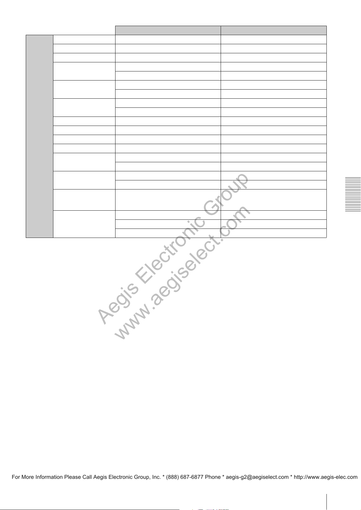
XCG-H280E XCG-H280CR
Aegis Electronic Group
www.aegiselect.com
For More Information Please Call Aegis Electronic Group, Inc. * (888) 687-6877 Phone * [email protected] * http://www.aegis-elec.com
General Lens Mount C mount C mount
Power Requirements DC +12 V (+10.5 V to +15.0 V) DC +12 V (+10.5 V to +15.0 V)
Power Consumption 5.8 W (max.) 5.8 W (max.)
Operating Temperature –10°C to +50°C –10°C to +50°C
14°F to + 122°F 14°F to + 122°F
Performance Quarantee
Tem pe ra tu re
Storage Temperature –30°C to +60°C –30°C to +60°C
Operating Humidity 20% to 80% (no condensation) 20% to 80% (no condensation)
Storage Humidity 20% to 95% (no condensation) 20% to 95% (no condensation)
Vibration Resistance
Shock Resistance 70 G 70 G
Dimensions (W × H ×
D)[[F_YS0001]]
Mass 200 g 200 g
Regulations UL2044, FCC Class A, CE: EN55022, AS/
Supplied Accessories Lens mount cap (1) Lens mount cap (1)
0°C to 40°C 0°C to 40°C
32°F to 104°F 32°F to 104°F
–22°F to +140°F –22°F to +140°F
50 × 50 × 57.5 mm (excluding protrusions) 50 × 50 × 57.5 mm (excluding protrusions)
2 × 2 × 2 3/8 inches (excluding protrusions) 2 × 2 × 2 3/8 inches (excluding protrusions)
7.1 oz 7.1 oz
NZ: EN55022, VCCI Class A, KC: KN22/
KN24 Class A
Connecter plug 2P (1) Connecter plug 2P (1)
Operating instructions (1) Operating instructions (1)
* “GigE Vision” is a registered trademark of the Automated Imaging Association (AIA).
UL2044, FCC Class A, CE: EN55022, AS/
NZ: EN55022, VCCI Class A, KC: KN22/
KN24 Class A
Specifications
43
Page 44
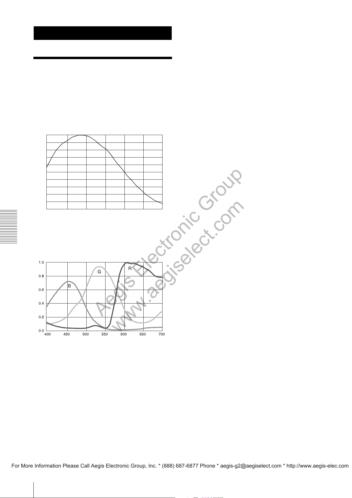
Appendix
Aegis Electronic Group
www.aegiselect.com
For More Information Please Call Aegis Electronic Group, Inc. * (888) 687-6877 Phone * [email protected] * http://www.aegis-elec.com
Spectral Sensitivity (Relative Response) Parameters
XCG-H280E
Camera Relative Response
1.0
0.9
0.8
0.7
0.6
0.5
0.4
0.3
0.2
0.1
0.0
400 500 600 700 800 900 1000
(Without lens and light source parameters.)
Wave Length [nm]
Appendix
XCG-H280CR
Camera Relative Response
Wave Length [nm]
(Without lens and light source parameters.)
44
Page 45
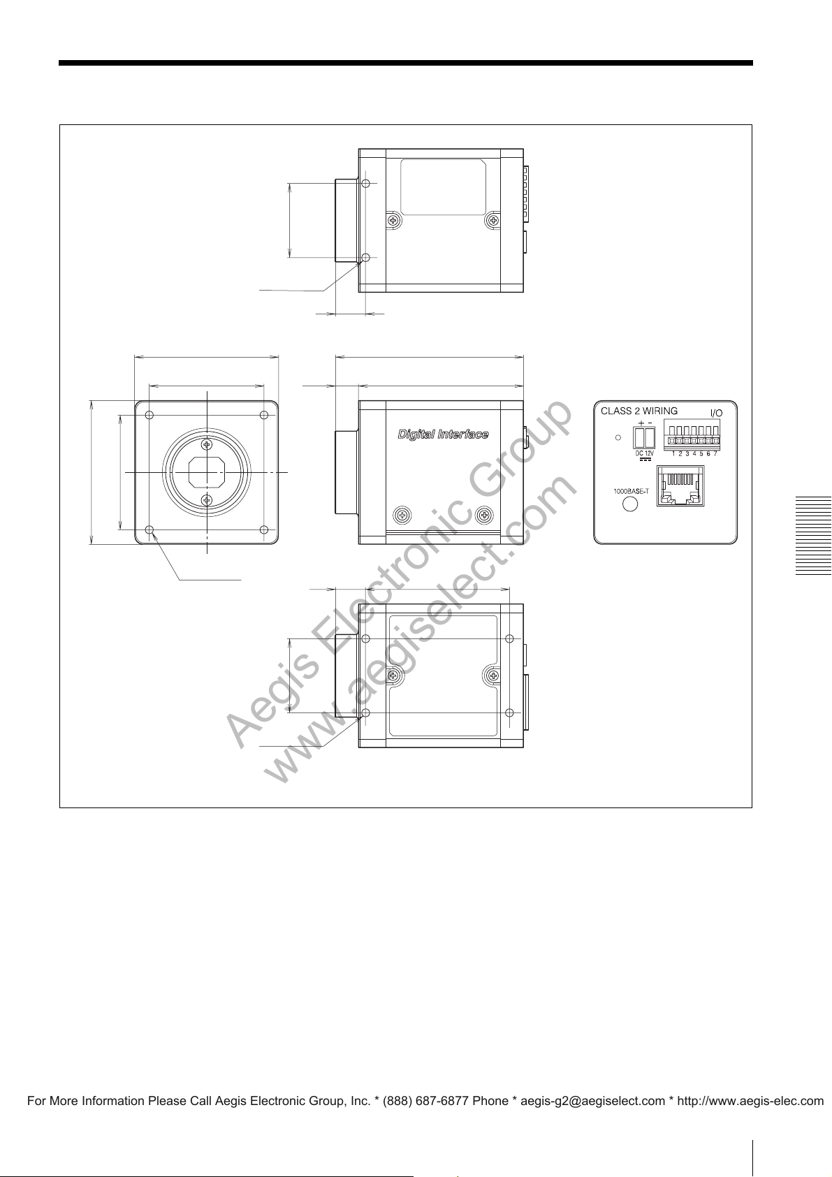
Dimensions
Aegis Electronic Group
www.aegiselect.com
For More Information Please Call Aegis Electronic Group, Inc. * (888) 687-6877 Phone * [email protected] * http://www.aegis-elec.com
)
16
/
1
26 (1
50 (2)
2-M3, depth 4
(2-M3, depth
50 (2)
5
40 (1
/8)
)
8
/
5
40 (1
4-M3, depth 4
(4-M3, depth
3
/16)
3
/16)
10.5
7
(
/16)
5
65.5 (2
(8)
11
(
/32)
10.5
(7/16)
)
16
/
1
57.5 (2
50 (2)
/8)
3
/8)
Appendix
26 (1
4-M3, depth 4
(4-M3, depth
3
/16)
Unit: mm (inches)
45
Page 46
Sony reserves the right to change specifications of the products and discontinue products without notice.
Aegis Electronic Group
www.aegiselect.com
For More Information Please Call Aegis Electronic Group, Inc. * (888) 687-6877 Phone * [email protected] * http://www.aegis-elec.com
Technical information contained herein is for reference only and does not convey any license by any implication or
otherwise under any intellectual property right or other right of Sony or third parties.
Sony cannot assume responsibility for any right infringements arising out of the use of this information.
Sony Corporation
 Loading...