

Page 1
Digital Video
Camera Module
C-189-100-11 (1)
Technical Manual
XCG-C30/C32/C130
XCG-C30C/C32C/C130C
© 2015 Sony Corporation
Page 2

Table of Contents
Overview
Features .................................................................. 3
Typical CCD Phenomena ...................................... 4
System Components .............................................. 5
Connection ............................................................. 6
Location and Function of Parts and
Operation ............................................................... 7
Front/Top/Bottom ............................................... 7
Using a tripod ..................................................... 7
Rear .................................................................... 8
Connecting the cables ........................................ 9
Controlling the camera from the host device ..... 9
When mounting the camera ............................. 10
Heat dissipation of the camera ......................... 11
The electrolytic capacitor during the PoE
operation ......................................................... 11
Connections
Network Settings ................................................. 12
Using Persistent IP ........................................... 12
Using DHCP .................................................... 12
Using LLA ....................................................... 12
Packet Size ....................................................... 12
Packet Delay ..................................................... 12
Network connection speed .................................. 13
Trigger Signal Input ............................................ 14
Trigger signal polarity ...................................... 14
GPIO Connector .................................................. 15
Frame Rate ...........................................................25
Auto frame rate .................................................25
Specifying frame rate ........................................25
Displaying frame rate .......................................25
Fastest frame rate for partial scanning ..............26
Timing Chart ........................................................28
Trigger latency ..................................................28
Sensor Readout (Sensor Output) ........................29
White Balance ......................................................30
LUT .......................................................................30
Binarization ......................................................30
5-point interpolation .........................................30
Arbitrary setting ................................................31
Save LUT ..........................................................31
Color Matrix Conversion ....................................31
3 × 3 filter ..............................................................32
Test Chart Output ................................................32
GPIO .....................................................................33
GPI ....................................................................33
GPO ..................................................................33
Pulse Train Generator .........................................35
Status LED ............................................................35
Temperature Readout Function .........................35
Sensitivity Control ...............................................35
User Set .................................................................35
User set memory ...............................................35
User ID ..................................................................36
Saving and Startup ..............................................36
Camera Information ............................................36
Restart ...................................................................36
Switching a CCD Driving Clock .........................36
Command List ......................................................37
Functions
Partial Scan .......................................................... 16
Binning ................................................................. 16
Output format ...................................................... 17
Gain ...................................................................... 17
Analog gain ...................................................... 17
Auto gain (AGC) .............................................. 17
Shutter (Exposure) .............................................. 18
Configuring the setting ..................................... 18
Auto exposure (AE) ......................................... 18
Combination of Continuous AGC and Continuous
AE ......................................................................... 18
Trigger Control .................................................... 19
Free run/trigger mode ....................................... 19
Special trigger .................................................. 20
Trigger source .................................................. 21
Trigger inhibition ............................................. 21
Trigger shift ...................................................... 22
Trigger delay .................................................... 23
Trigger counter ................................................. 23
Trigger range limit ........................................... 23
Trigger control .................................................. 24
Specifications
Specifications ........................................................45
Spectral Sensitivity Characteristics (Typical
Values) ...................................................................46
Dimensions ............................................................48
2
Table of Contents
Page 3
Overview
Before operating the unit, please read this manual
thoroughly and retain for future reference.
Partial scan (during DC IN power supply
only)
The camera module can limit the number of video
output lines to achieve high frame rates, enabling highspeed image processing.
Overview
This unit is a digital video camera module that adopts
the 1000BASE-T/100BASE-TX interface.
Features
GigE Vision compliant
This unit supports GigE Vision Ver.2.0/Ver.1.2, and the
versions are switchable by changing the settings.
High image quality
All cameras feature a progressive scan CCD for highresolution images. Both cameras produce stable output
images, by adopting the proven CCD.
By adopting square pixels, images can be processed
using the original aspect ratio without a converting
procedure.
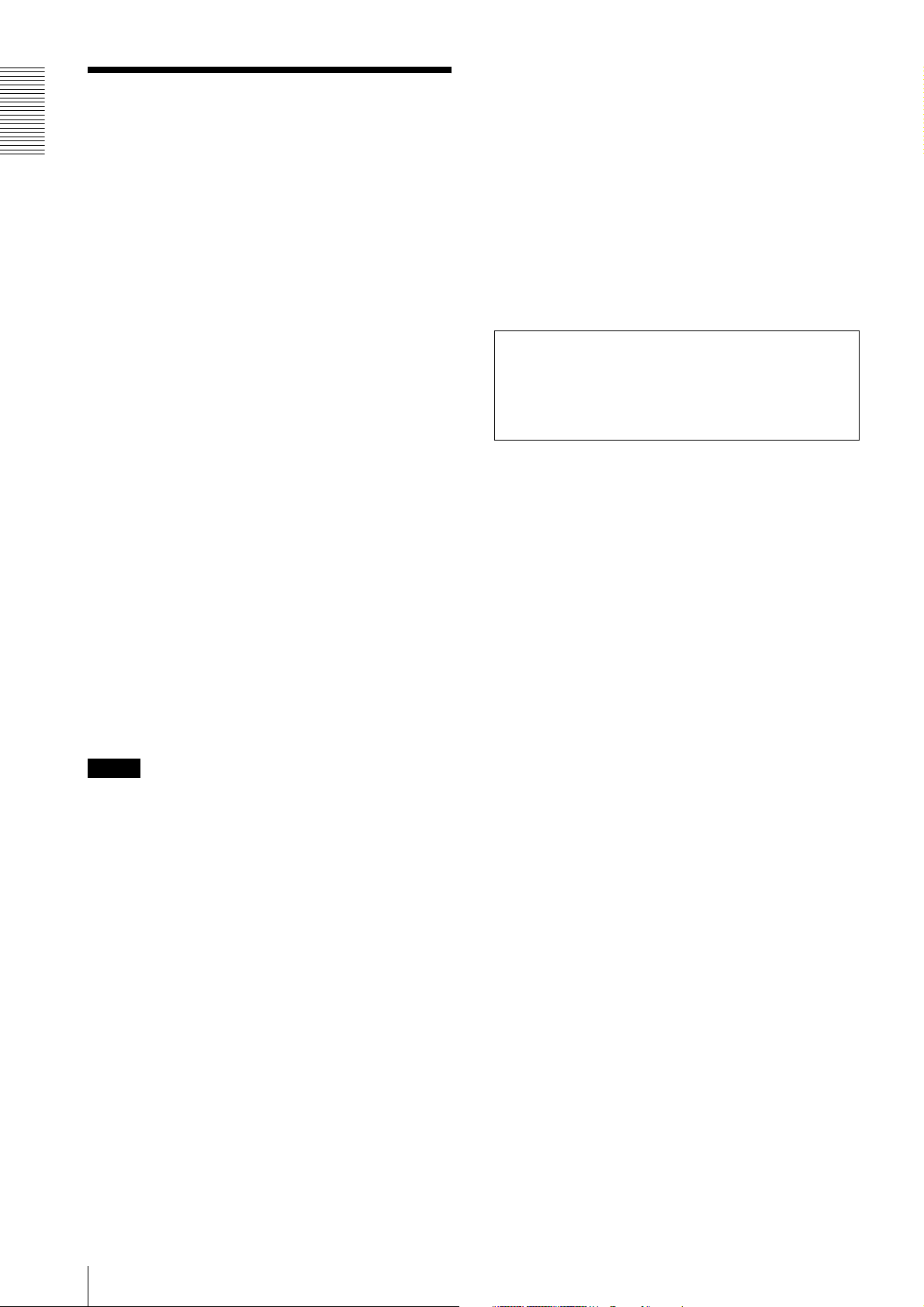
The following models and their CCDs are shown below.
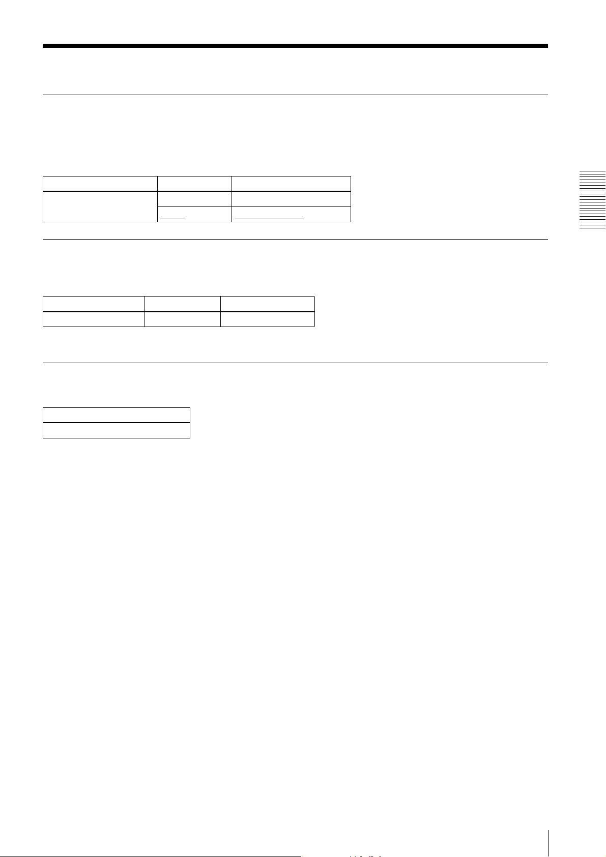
Model name Pixel count
XCG-C30/C32/C30C/
C32C
XCG-C130/C130C 1,300,000-pixel CCD,
330,000-pixel CCD, compatible
with VGA
compatible with SXGA
Body fixing
The screw holes to install the camera module are located
under the front panel (the CCD reference plane).
Installing the camera module on the front panel
minimizes deviation of the optical axis.
LUT (Look Up Table)
You can switch to OFF or ON. When set to ON, you can
select from five preset values, such as inversion,
binarization, settable five-point approximations, etc.
Switching an Output Bit Length
You can select 8-bit output, 10-bit output, or 12-bit
output.
For color models, you can also select an output of RGB
24-bit, YUV 24-bit, or YUV 16-bit.
Binning (during DC IN power supply/
black and white camera only)
Sensitivity can be doubled by combining two pixels
aligned vertically, you can achieve a standard output
frame rate between 1.8x and 2x. Sensitivity can be
doubled by combining two pixels align horizontally.
You can set horizontal and vertical binning at the same
time.
Various settings
Sending a command from the host device allows various
settings, including the following.
•Gain
•Shutter
• Partial scan (during DC IN power supply only)
• Trigger control
• LUT (Look Up Table)
• Output: 8/10/12-bit, RGB 24-bit, YUV 24-bit
(YUV444), or YUV 16-bit (YUV422)
Electronic shutter function
Set anywhere from 1/100,000 sec to 2 sec in 1 µs
increments. If you do not prioritize the image quality,
you can set it up to 60 sec during operation.
External trigger shutter function
By synchronizing with an external trigger signal, any
shutter timing can be used.
White balance control (color camera
only)
You can adjust the R and B level against G level to adjust
the white balance. This unit is also equipped with the
one-push white balance function, by which the camera
can automatically adjust the white balance.
Note
The CCD is driven at high speed during a Partial scan or
Binning operation. In this situation, if intense light is
input to the camera, the peripheral areas of the video
image may be affected. In such a situation, adjust the
amout of light using the iris.
Features
3
Page 4
CCD used in XCG-C130/C130C
Typical CCD Phenomena
The following effects on the monitor screen are
Overview
characteristic of CCD cameras. They do not indicate any
fault with the camera module.
Smear
This occurs when shooting a very bright object such as
electric lighting, the sun, or a strong reflection.
This phenomenon is caused by an electric charge
induced by infrared radiation deep in the photosensor. It
appears as a vertical smear, since the CCD imaging
element uses an interline transfer system.
Vertical aliasing
When you shoot vertical stripes or lines, they may
appear jagged.
Under the following operating conditions, because the
construction of the CCD of this camera is different from
the CCDs used in other cameras, the brightness level
near the pedestal may increase, or white dots described
above may become pronounced, degrading the image
quality.
• When used in a hot environment
• When the gain is increased
• When the exposure time is long (0.1 second or longer)
In these situations, decrease the environmental
temperature, or adjust the light source or lens aperture,
and change the camera gain or exposure time.
Note on laser beams
Laser beams may damage a CCD. You are cautioned
that the surface of a CCD should not be exposed to
laser beam radiation in an environment where a laser
beam device is used.
Blemishes
A CCD image sensor consists of an array of individual
sensor elements (pixels). A malfunctioning sensor
element will cause a single pixel blemish in the picture
(This is generally not a problem.).
White speckles
While CCD image pickup device is made by an accurate
technique, imperceptible speckless may rarely come up
on the screen due to cosmic rays and so on. This is
connected to the principle of CCD image pickup device,
not a malfunction. And the white speckless are easy to
come up in the following conditions.
• Using the camera in high temperature
• When turning up the gain
Note
If strong light enters a wide area of the screen, the screen
may become dark. This is not a malfunction.
If this occurs, avoid strong light or adjust the lens iris to
reduce the light amount.
4
Typical CCD Phenomena
Page 5
System Components
a
cd e
fg
b
g LAN cable
This cable connects to the RJ45 connector on the rear
panel of the camera module.
Image/control signals are transmitted via this cable. Use
a LAN cable (CAT5e or higher standard) that supports
1000BASE-T (or allows 100BASE-TX when it is used).
Depending on the attributes of the LAN cable, images
may become less clear and the camera module may
become unstable. Be sure to use a LAN cable that has
sufficient noise reduction.
Note
When you connect the LAN cable of the unit to
peripheral device, use a shielded-type cable to prevent
malfunction due to radiation noise.
Overview
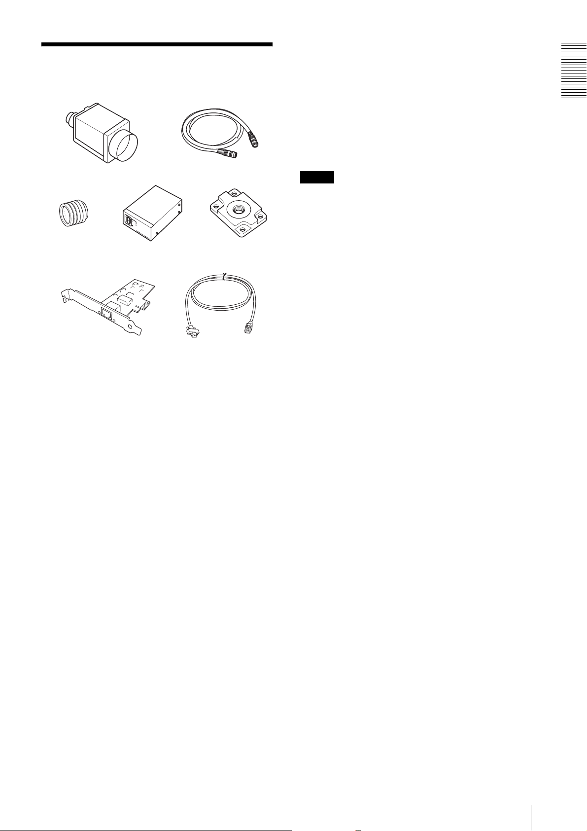
The video camera module system comprises the
following optional products (available separately).
a Video Camera Module
This is a small-size, high image-quality video camera
module that uses a progressive scan CCD image sensor.
b Camera cable
This is attached to the DC IN connector of the camera
module and is used for power supply and exchange of
trigger signals.
For purchasing the cable, consult the dealer.
c C-mount lens
Use a suitable lens to fit the camera pixel count.
d DC-700/700CE camera adaptor
This is connected to the camera module to enable power
supply from ordinary AC power source.
e VCT-333I tripod adaptor
This attaches to the bottom of the camera module to fix
the camera module to a tripod.
f Camera module interface board (Network
interface card)
Install the board in the expansion slot of the host device
(ex: computer). Use a board that is appropriate for your
system and that supports 1000BASE-T (or allows
100BASE-TX when it is used) and jumbo packets.
System Components
5
Page 6
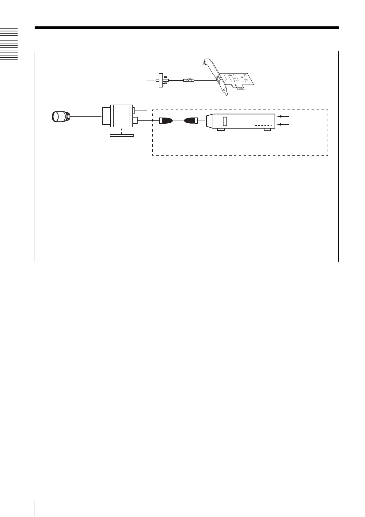
Connection
Overview
LAN cable
Camera module
C-mount lens
Camera cable
Tripod adaptor
VCT-333I
If the HUB supports PoE, the items within the dashed line are not necessary.
Power supply
You can supply power to the camera module using the following methods.
Using the RJ45 connector
This unit supports PoE (IEEE802.3af standard). By using a PoE-compatible LAN cable and camera module interface board or hub,
you can power, control, and output images from the camera using one LAN cable.
When you operate this unit using PoE, heat dissipation is required depending on the usage environment because the inside of the
camera becomes hot.
For heat dissipation, refer to the User's Guide.
Camera module interface board
AC
TRIG
Camera adaptor
DC-700/700CE
(adopt EIAJ compliant 12-pin
connector pin assignments)
Using the DC IN connector
You can supply power via the DC IN connector using the power adapter.
Use DC-700/700CE which is the stable power source free from ripple or noise.
6
Connection
Page 7
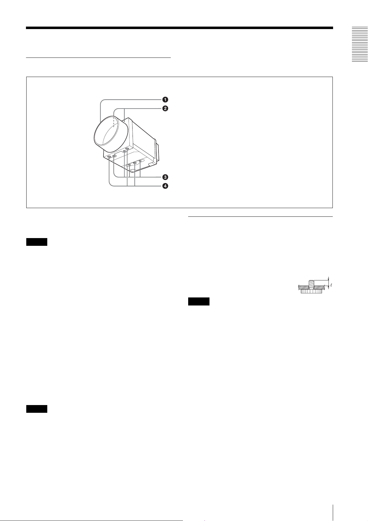
Location and Function of Parts and Operation
Front/Top/Bottom
a Lens mount (C-mount)
Attach any C-mount lens or other optical equipment.
Note
The lens must not project more than 10 mm (13/32 inch)
from the lens mount.
When you use the camera with the lens attached, the
resolution of the image output from the camera may
differ according to the performance of the lens. Note it
when you select a lens.
The performance of a lens may change according to the
aperture level.
If the resolution is not enough, adjust the aperture level.
b Guide screw holes (Top)
Overview
Lens mount (C-mount)
Guide screw holes (Top)
Guide screw holes/Tripod screw holes (bottom)
Reference screw holes (bottom)
Using a tripod
To use the tripod, install the tripod adaptor VCT-333I
(not supplied) on the camera module.
Use a tripod screw with a protrusion (4) extending from
the installation surface, as follows, and tighten it, using
a screwdriver. Be sure that the protrusion (4) does not
exceed 5.5 mm (0.2 in.) in length.
Length 4.5 to 5.5 mm
Length 0.18 to 0.22 inches
Note
If you install a tripod adapter (not supplied), use the
screws provided.
c Guide screw holes/Tripod screw holes (bottom)
When using a tripod, use these four screw holes to attach
a VCT-333I tripod adaptor.
d Reference screw holes (bottom)
These precision screw holes are for locking the camera
module. Locking the camera module into these holes
secures the optical axis alignment.
Note
Refer to XCG-C30 Demensions in page 48 for about the
position/size of the Guide hole and the Reference hole.
Location and Function of Parts and Operation
7
Page 8
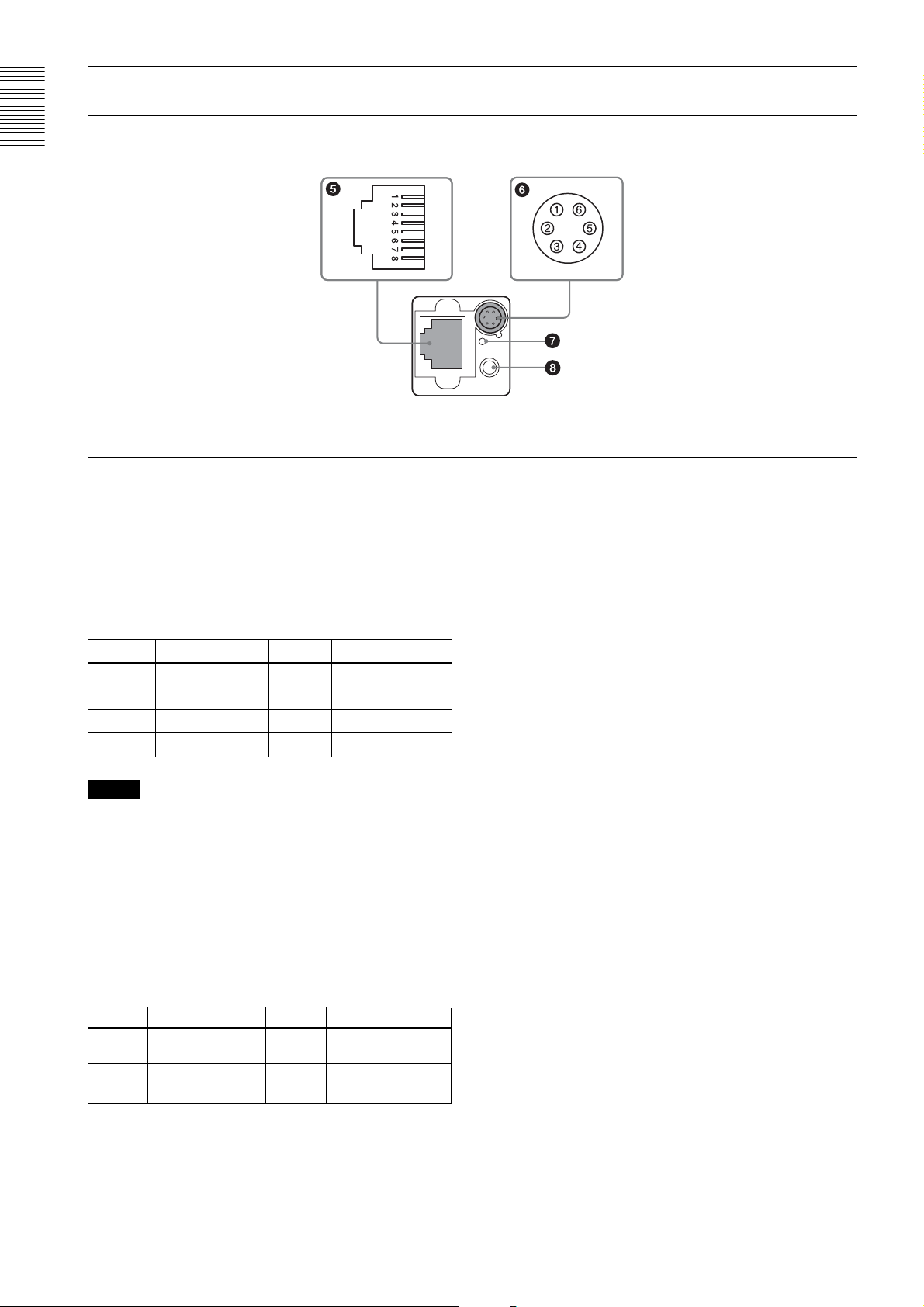
Rear
Overview
e RJ45 connector
You can connect a LAN cable to this connector to
control the camera module from a host device to output
image to a host device. By using a PoE-compatible LAN
cable and camera module interface board or hub, you
can supply power using the LAN cable.
(Refer to Fig.
5 above for the pin assignment of the
connector.)
Pin No. Signal Pin No. Signal
1TP3 + 5TP1 –
2TP3 – 6TP2 –
3TP2 + 7TP4 +
4TP1 + 8TP4 –
Note
For safety, do not connect the connector for peripheral
device wiring that might have excessive voltage to this
port. Follow the instructions for this port.
f DC IN (DC power input) connector (6-pin)
You can connect a camera cable to input the +12 V DC
power supply. The pin configuration of this connector is
as follows.
(Refer to Fig.
6 above for the pin assignment of the
connector.)
g Reset switch
This reformats the network settings.
h Status LED (Green)
When power is on, this LED lights up.
Pin No. Signal Pin No. Signal
1 DC input (10.5 V
to 15 V)
2 GPI1 (ISO +) 5 GPI1 (ISO –)
3 GPI2/GPO2 6 GND
8
Location and Function of Parts and Operation
4 GPI3/GPO3
Page 9
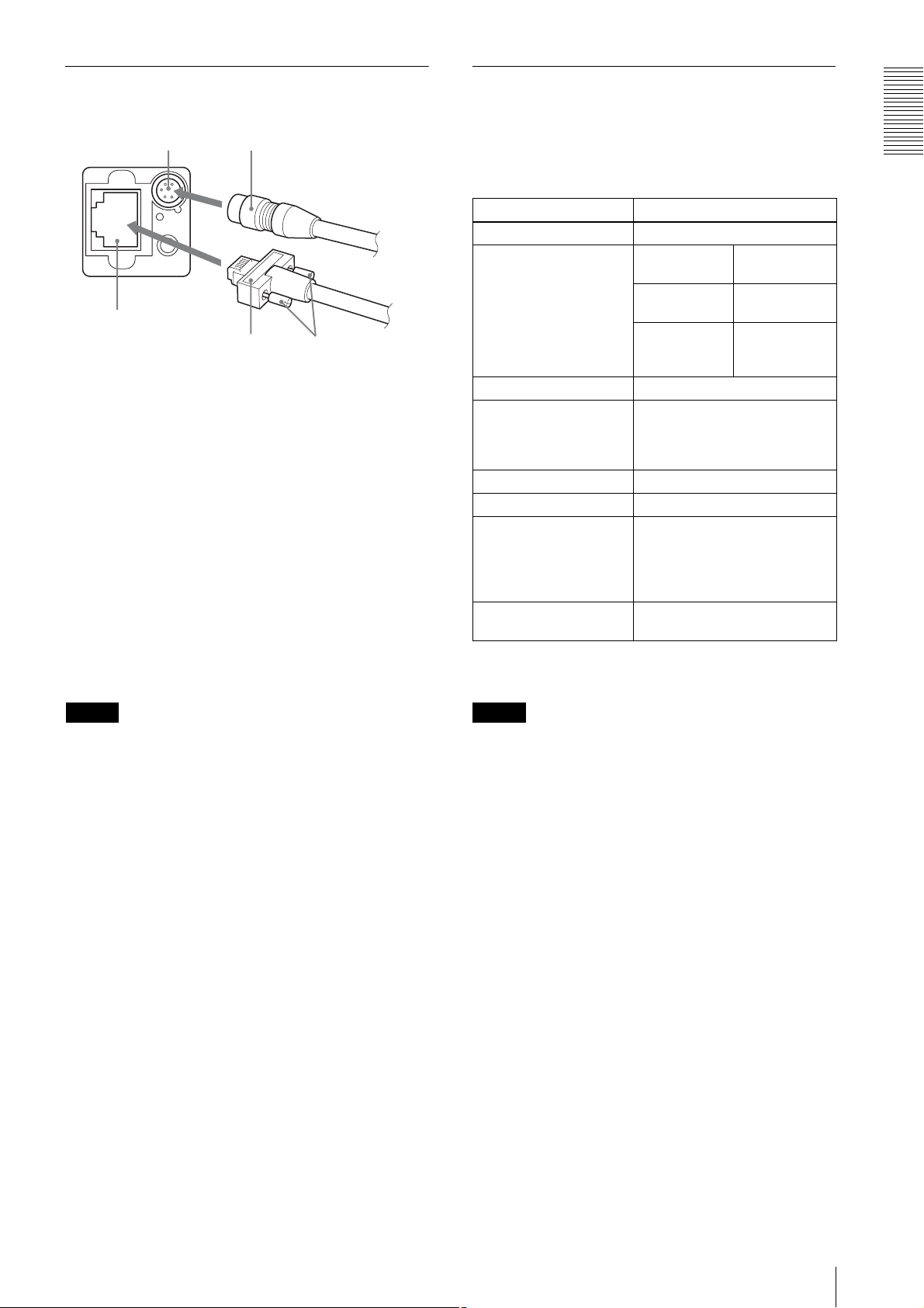
Connecting the cables
Controlling the camera from the host device
Connect the camera cable to the DC IN connector and
connect the LAN cable to the RJ45 connector
respectively. If you use a camera module interface board
or a hub with support for PoE, you can operate the
camera even if you do not connect the camera cable to
the DC IN connector. When you connect the LAN cable
with fastening screws, turn the two screws on the
connector to secure the cable tightly.
1 DC IN connector 2 RJ45 connector
3 Camera cable 4 LAN cable
5 Fastening screws
Connect the other end of the camera cable to the DC700/700CE and the other end of the LAN cable to the
camera module interface board or a hub.
You can control the camera from host devices such as a
computer. The following table shows the major control
functions.
Control functions Description
Operating mode Free run/Trigger
Shutter speed* Free run 1/100,000 sec to
2 sec
Trigger edge
detection
Trigger pulse
width detection
Gain 0 dB to 18 dB
Partial Scan (during DC
IN power supply only)
LUT (Look Up Table) OFF/ON (Mode: 5 types)
External trigger input DC IN connector
Video output switch Monochrome model: Mono 8/10/
Binning (during DC IN
power supply only)
Variable, 2-line increments (the
number of settable lines is 32 or
more/the recommended setting is
120 lines or more)
12-bit
Color model: Raw 8/10/12-bit,
RGB 24-bit, YUV 24-bit, YUV
16-bit
2×1, 1×2, 2×2
1/100,000 sec t o
2 sec
Setting by
trigger pulse
width
*If you do not prioritize the image quality, you can set
the shutter speed up to 60 sec during operation.
Overview
Note
Do not supply power to the camera cable and LAN cable
at the same time.
Note
Make sure to supply power to the camera module and
confirm that the camera module is operating before
inputting a trigger signal. If you input trigger signal to a
camera module without the power supplied, this may
cause a malfunction of the camera module.
Do not exit the application software of the host device
before completing the image transmission from the
camera. This may cause a malfunction on the camera.
Location and Function of Parts and Operation
9
Page 10
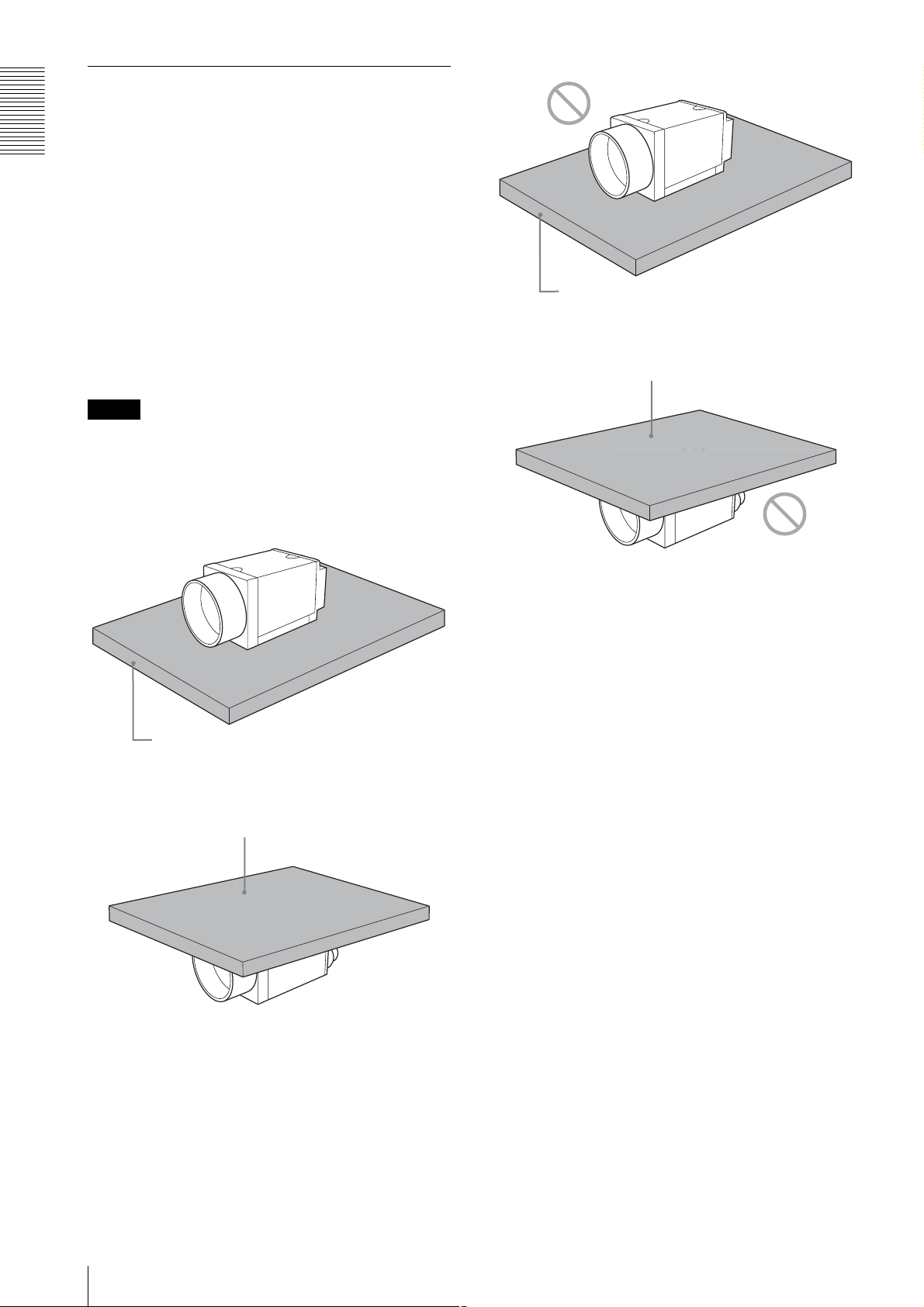
When mounting the camera
When you operate this unit in the following conditions,
heat dissipation is required depending on the usage
Overview
environment because the inside of the camera becomes
hot.
• when using PoE system
• when the partial scan is set to less than 120 lines
during the power is supplied through DC IN
To promote heat dissipation from the unit and maintain
performance, mount the camera to a metallic heat
dissipation plate.
Dimension of the heat dissipation plate: 180 mm ×
110 mm × 5 mm or more (Thermal conductivity:
16.3 W/m·K or more)
For heat dissipation, refer to the User's Guide.
Notes
• When mounting the camera to the heat dissipation
plate, secure the camera tightly by using the reference
screw holes (see page 7) and screws.
• Do not mount the camera to a plate made of a material
such as wood or resin that prevents heat dissipation.
Plate that prevents heat dissipation
(made of wood, resin, etc.)
Plate that prevents heat dissipation
(made of wood, resin, etc.)
Metallic heat dissipation plate
Metallic heat dissipation plate
10
Location and Function of Parts and Operation
Page 11
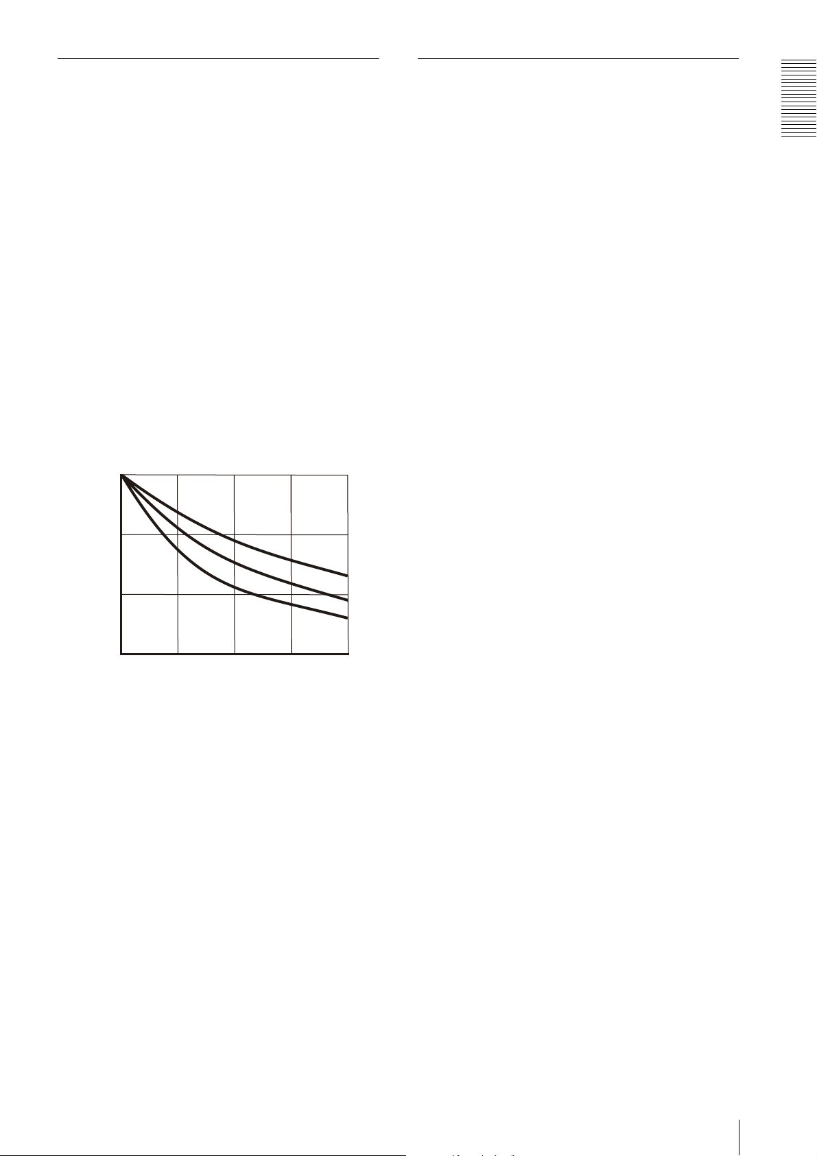
Heat dissipation of the camera
The electrolytic capacitor during
• Use this camera in an environment that the read value
of the temperature sensor is 68°C (154.4°F) or less
during PoE mode.
• The read value of the temperature sensor becomes
high if the temperature around the camera is high.
When the read value is higher than 68°C (154.4°F),
mount a heat dissipation plate to the camera.
• If you use a larger heat dissipation plate, it is possible
to lower the read value of the temperature sensor.
The read value of the temperature sensor can be
obtained by the following formula:
Read value of temperature sensor =
Temperature around the camera + Temperature inside
the camera
The relation between the heat dissipation plate area
and the temperature inside the camera is shown in the
following graph:
(The heat dissipation differs depending on the
material.)
35/95
the PoE operation
This unit has an electrolytic capacitor.
This electrolytic capacitor is not powered on during the
DC IN operation. It is powered on during the PoE
operation.
When the power is supplied by PoE, the electrolytic
capacitor is designed to work for more than 3 years
without any problems even if it is operated for 24 hours
under an environment at a temperature of 40°C (104°F).
Also, if the operating time is 8 hours per day, the life
expectancy is 3 times the above mentioned period.
Periodic inspections are recommended if it is used for a
long time.
◆ Contact a Sony sales representative for more
information about inspections.
Overview
30/86
SUS
25/77
Temperature inside the camera (˚C/˚F)
20/68
0
Heat dissipation plate area (cm2) *Thickness: 0.5 cm (7/32 inches)
50 100 150
Fe
Al
200
Location and Function of Parts and Operation
11
Page 12

Connections
Connections
Network Settings
For the camera to be connected to a network, the
following address data must be properly specified:
• IP address
• Subnet mask
• Default gateway
The camera provides the following three methods for the
address data setting:
• Using Persistent IP
• Using DHCP
• Using Link Local Address (LLA)
Using Persistent IP
Use this method when the IP address to be assigned to
the camera has been specified in advance. When using
the persistent IP, subnet mask and default gateway
settings are also required. When using persistent IP
forwarding on a router, default gateway settings are also
required.
Packet Delay
The delay amount to be inserted between packets can be
set when sending them to a network. By increasing the
packet delay, you can reduce the network bandwidth that
the camera uses for sending packets. However, as the
amount of data sent in a certain time is decreased with
increased delay, the frame rate of output images of the
camera may be consequently decreased.
Using DHCP
The camera is equipped with a function to automatically
obtain an IP address by communicating with a DHCP
server on a network. When using the DHCP method for
IP address setting, the subnet mask and default gateway
values automatically obtained from the DHCP server are
also used.
Using LLA
If neither Persistent IP nor DHCP is used, or if an IP
address cannot be obtained from the DHCP server, the
IP address is determined by LLA. The IP address
determined by LLA will be 169.254.XXX.YYY, with
XXX and YYY automatically specified.
In addition, the following network settings can be
changed.
• Packet size
• Packet delay
Packet Size
The amount of image data per packet can be set in bytes.
To permit the camera to operate properly, set the packet
size to a value less than the MTU of the network device
connected to the camera. Set the largest value in the
networks including the hub.
12
Network Settings
Page 13
Network connection speed
This unit supports the connection with 1000Base-T
(1 Gbps) or 100Base-TX (100 Mbps).
When you connect the unit to the network, negotiate the
communication speed with the connected equipment
and start communication at a higher speed of that both
equipment are compatible with.
When using the unit with 100Base-TX connection, the
frame rate to be output is limited, because the output
data band width from the camera becomes narrow
compared to the 1000Base-T connection.
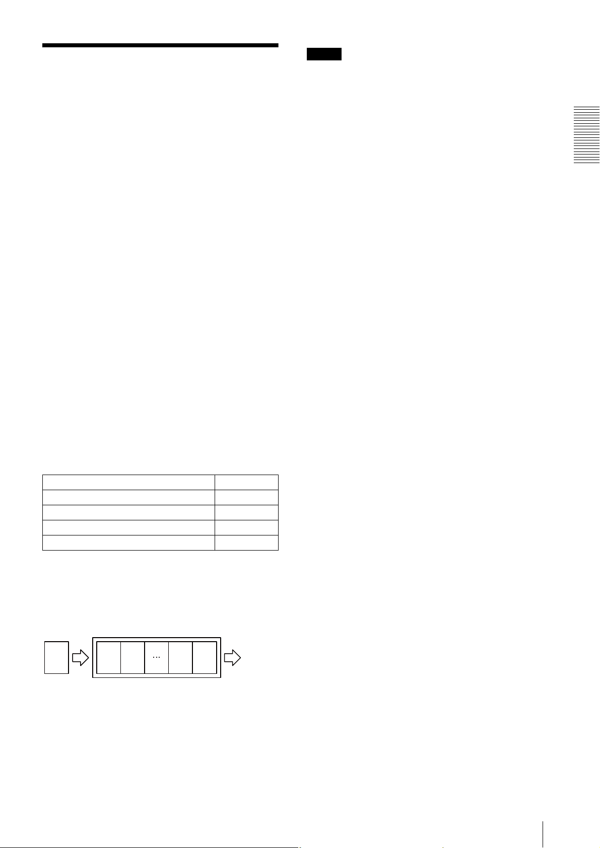
The camera has a buffer to store multiple images and all
of the shot images are stored once in the buffer.
The stored images are output from the camera in order
starting from the oldest image in the buffer.
Therefore, if the frame rate during shooting is faster than
the frame rate that can be output from the camera, the
image data will always be stored in the buffer, and the
time interval from shooting to image output becomes
large.
To avoid this situation, it is required to set the shooting
frame rate to the proper value when using 100Base-TX
connection.
The data rate of images is obtained by the following
formula:
Notes
• Any persistent IP address can be entered, but the
camera may become unable to be detected, depending
on the IP address setting. If this occurs, use a tool for
issuing ForceIP and set a persistent IP address again.
• When setting the parameters (Width, Height, and
PixelFormat) for calculating the payload size, stop
camera image output beforehand.
Connections
Data rate = Width
× Height × BPP × FPS
Width: Width of image
Height: Height of image
BPP: The number of bits per pixel depends on the
PixelFormat setting
Mono8/BayerRG8 8-bit
Mono10Packed/BayerRG10Packed 12-bit
Mono12Packed/BayerRG12Packed 12-bit
RGB8Packed/BRG8Packed/YUV8_UYV 24-bit
YUV422_8/YUV422_8_UYVY 16-bit
FPS: Frame rate [frame/sec]
It is possible to minimize delay by using the camera at a
frame rate where the data rate becomes low with a
margin against 100 Mbps.
Buffer
CCD
Image nImage
n
Image 2Image
1
Image
output
Network connection speed
13
Page 14

Connections
Trigger Signal Input
Trigger signals can be input via the 2nd, 3rd, 4th pins of the DC IN connector, or the software command. Switchover of
the trigger signal can be changed via the TriggerSource register.
Register Parameter Setting
TriggerSource Line1 (0)
Line2 (1) DC IN connector 3rd pin (GPI2) *
Line3 (2) DC IN connector 4th pin (GPI3) *
Software (4) Software (TriggerSoftware register)
* The 3rd and 4th pins of DC IN connector are available only when the input/output switching setting is set to input.
Trigger signal polarity
Positive refers to a trigger signal polarity activated while rising from Low to Hi, or during the Hi interval. Negative refers
to a trigger signal polarity activated while falling from Hi to Low, or during the Low interval.
Register Parameter Setting
TriggerActivation FallingEdge (0)
RisingEdge (1) Positive
DC IN connector specifications
DC IN connector 2nd pin (GPI1)
Negative
5 to 24 V (DC IN connector 2nd pin)
3.5 to 5.5 V (DC IN connector 3rd
and 4th pins)
0 to 0.4V
2.0µs or less
10µs to 2s
2.0µs or less
100µs or more
Trigger input polarity = Negative
5 to 24 V (DC IN connector 2nd pin)
3.5 to 5.5 V (DC IN connector 3rd
and 4th pins)
0 to 0.4V
2.0µs or less
10µs to 2s
2.0µs or less
100µs or more
Trigger input polarity = Positive
Note
When inputting a trigger signal to the camera using the DC-700/CE, use DC 5 V or less at the logical high level.
14
Trigger Signal Input
Page 15

GPIO Connector
The 2nd DC IN connector is the GPI connector and the 3rd and 4th are connectors that can set to either GPI or GPO.
The trigger reset pin is the DC IN connector 2nd pin (GPI1). If you are connecting an external device to the GPI or GPO
connector, refer to the circuit specifications below.
GPI circuit specifications
5V
HCPL-M611
GPIO circuit specifications
GPI2/GPO2
180
MMBF4393LT1G
DC IN connector
DA2710100L
DC IN connector
#3
Connections
#2
#5
GPI3/GPO3
As GPI2/GPO2
#4
GPIO Connector
15
Page 16
Functions
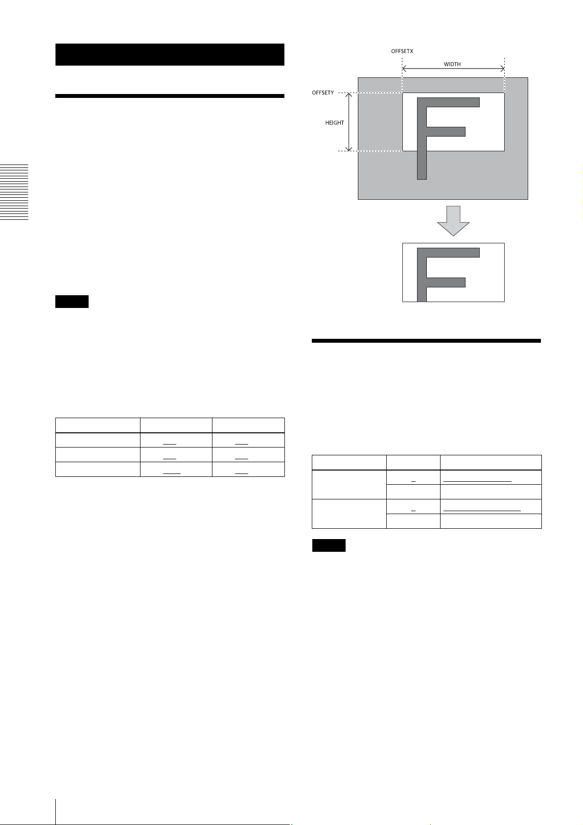
Partial Scan
Only the area selected from the effective pixel area can
be read out. Clearing unnecessary parts at high-speed
allows high-speed reading. The area size is selected by
the Height and Width registers, and the read beginning
point is selected by the OffsetX and OffsetY registers.
Reducing Height increases the frame rate, but changing
the Width register does not change the frame rate. Partial
Functions
scan can be set with or without a trigger. Binning can be
used at the same time.
OffsetX and OffsetY relate to Width and Height as
follows:
OffsetX + Width
OffsetY + Height
Notes
≤ Width (maximum value)
≤ Height (maximum value)
• Since the shutter setting has priority, use a shutter
speed high enough to enable partial scan at a higher
frame rate.
• When the power is supplied by PoE, you cannot set the
Height setting to a setting lower than the standard
setting.
Binning
By adding 2 vertical pixels or 2 horizontal pixels, the
frame rate in vertical binning is increased along with the
Configurable range
sensitivity. The color camera cannot set this. This can be
set with or without a trigger. Partial scan can be used
Width Height
XCG-C30/C 16 to 640
XCG-C32/C 16 to 640
XCG-C130/C 16 to 1280
to 658 32 to 480 to 494
to 658 32 to 480 to 494
to 1296 32 to 960 to 966
Configurable values
The values of OFFSETX, OFFSETY, WIDTH and
HEIGHT increase or decrease in steps of 2.
concurrently and horizontal and vertical can be set at the
same time.
Register Parameter Setting
BinningVertical 1
2 Vertical binning
BinningHorizontal 1
2 Horizontal binning
No vertical binning
No horizontal binning
Partial scan
16
Notes
• The binning function is disabled when the power is
supplied by PoE.
• Use a shutter speed high enough to enable binning at
a higher frame rate.
Partial Scan
Page 17
Output format
Monochrome cameras can switch between 8 bits, 10
bits, and 12 bits. Color cameras can switch between Raw
output 8 bits, 10 bits, 12 bits, RGB output 24 bits, and
YUV output 24 bits, 16 bits.
Register Parameter Setting
PixelFormat
(Monochrome
camera)
PixelFormat
(Color camera)
Mono8
Mono10Packed 10 bits
Mono12Packed 12 bits
BayerRG8
BayerRG10Packed 10 bits (color camera)
BayerRG12Packed 12 bits (color camera)
RGB8Packed RGB 24 bits (RGB)
BGR8Packed RGB 24 bits (BGR)
YUV8_UYV YUV 24 bits
YUV422_8_UYVY YUV 16 bits (UYVY)
YUV422_8 YUV 16 bits (VYUY)
8 bits
8 bits (color camera)
Gain
Register Parameter Setting
GainAutoMode Off (0)
Once (1) One-push AGC
Continuous (2) Continuous AGC
GainAutoLevel 0 to 11264
GainAutoSpeed
GainAutoUpperLimit
GainAutoLowerLimit
DetectAreaGainAuto
DetectAreaGainAutoWidth
DetectAreaWBAutoHeight
DetectAreaWBAutoOffsetX
DetectAreaWBAutoOffsetY
1 to 256
–27 or less ~ 502
752 or more
–27 or less ~ 0
752 or more
Off (0)
On (1) AGC detection frame is
to 100 Width size of AGC
0 to 50
to 100 Height size of AGC
0 to 50
to 100 Horizontal position of
0 to 25
to 100 Vertical position of
0 to 25
to 16383 AGC target level
Manual gain
(14 bits)
AGC convergence
speed
~
AGC upper limit
~
AGC lower limit
AGC detection frame is
hidden
displayed
detection frame
detection frame
AGC detection frame
AGC detection frame
OsetX
Functions
Analog gain
The analog gain can be finely set in 0.0359 dB units or
bit levels.
Although the settable lower/upper limit values of the
gain are slightly different in each camera, the gain
parameter value can be set from –1 dB or less to 27 dB
or more. Same as the gain, the parameter value of the
GainAnalogRaw can be set from –27 or less to 752 or
more. The setting rage of the gain that guarantees image
quality is from 0 dB to 18 dB.
Register Parameter Setting
Gain –1 or less ~ 0
more
GainAnalogRaw –27 or less ~ 0
more
~ 27 or
~ 752 or
Gain dB unit
Gain advanced
setting
Auto gain (AGC)
By setting AUTOGAIN, the gain is automatically
adjusted according to the image pickup environment.
AGC works so that the average level in a detection frame
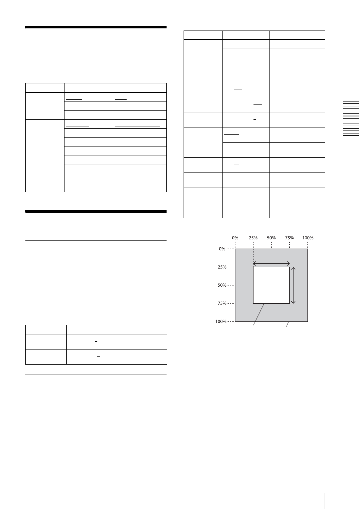
may reach AGC-LEVEL. The AGC detection frame is
set to the central region by default. The detection frame
can be displayed or the detection area changed.
OsetY
Detection frame area
Width
Height
Whole screen
Output format
17
Page 18
Shutter (Exposure)
Combination of
Continuous AGC and
Configuring the setting
Continuous AE
The setting is configured in µs unit. With the default
shutter value, the frame rate is maximized. During free
run operation, the frame rate is reduced by setting a
value bigger than the default shutter value. If you do not
prioritize the image quality, you can set it up to 60 sec
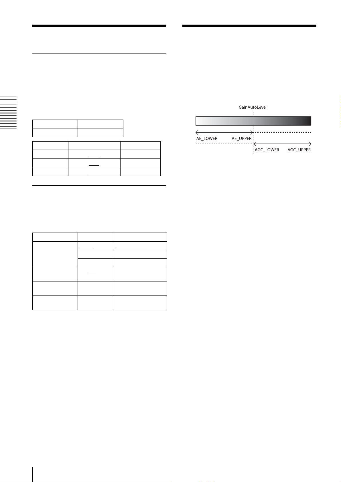
AGC and AE coordinate with each other to adjust the
level automatically with GainAutoLevel as the target
level. When the environment starts getting dark and AE
reaches the upper limit, AGC starts to work.
during operation. The exposure time that guarantees
image quality is up to two seconds.
Register Parameter
Functions
ExposureTime 10 to 60000000
Exposure Time [us] Rate [fps]
XCG-C30/C 7674
XCG-C32/C 9593
XCG-C130C 32169
130
104
31
Bright Dark
AE
AGC
Auto exposure (AE)
The shutter is set automatically by detecting the output
level. The target level is the same as the value of
GainAutoLevel. This can be performed along with auto
gain.
Register Parameter Setting
ExposureAutoMode Off (0)
Once (1) One-push AE
Continuous (2) Continuous AE
ExposureAutoSpeed
ExposureAutoUpperLimit
ExposureAutoLowerLimit
1 to 192
10 to 2000000 AE upper limit
10 to 2000000 AE lower limit
to 256 AE convergence speed
Manual shutter
18
Shutter (Exposure)
Page 19
Trigger Control
Free run/trigger mode
Free run
The camera operates without a trigger signal and performs the video output operation continuously after the shutter
(exposure) is finished. The horizontal and vertical timing signals are generated within the camera. During the free-run
operation, image pickup timing cannot be controlled. In the free-run operation, the adjustment is made automatically to
achieve the maximum frame rate according to the shutter setting.
Trigger mode
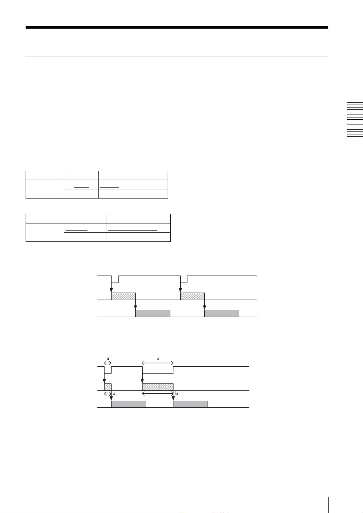
Exposure is started by detecting the externally input trigger signal. When ExposureMode is 0, exposure is started by
detecting the rising or falling edge of the trigger signal and the trigger edge detection (exposure is performed based on
the set shutter value) is performed. When ExposureMode is 1, the trigger width detection (exposed for the period of the
trigger signal width) is performed.
Register Parameter Setting
TriggerMode Off (0)
On (1) Trigger mode
For trigger mode (TriggerMode=On)
Register Parameter Setting
ExposureMode Timed (0)
TriggerWidth (1) Trigger width detection
Free run
Trigger edge detection
Functions
Trigger edge detection
The figure shows the trigger signal negative polarity (detecting the drop edge).
Trigger signal
Exposure
Sensor output
Trigger width detection
The figure shows the trigger signal negative polarity (detecting Low level width).
Trigger signal
Exposure
Sensor output
Trigger Control
19
Page 20
Special trigger
When operating in trigger mode and performing image pickup in different conditions (such as the shutter, gain, and
image pickup area), the setting has to be changed in advance for each trigger input. However, if the special trigger
operation is enabled, the setting does not have to be changed and continuous image pick up in different conditions is
facilitated. Up to 16 settings can be configured. There are the bulk operations in which images are taken consecutively
by inputting the trigger signal once and the sequential operation in which images are taken each time the trigger signal
is detected. The next exposure is started after the end of video output. In the sequential operation, the second and
subsequent trigger signals should be input 5 ms or more after the end of video output. The special trigger operation and
trigger mode operation cannot be enabled at the same time. The source and polarity of the special trigger signal should
be defined separately from the trigger mode. Each setting should be saved in the user set. For the items reflected, refer
to “Command List” (page 37).
Register Parameter Setting
SpecialTriggerMode Off (0)
Functions
Register Parameter Setting
SpecialTriggerSource Line1 (0)
Bulk (1) Bulk trigger
Sequential (2) Sequential trigger
Line2 (1) DC IN connector 3rd pin
Line3 (2) DC IN connector 4th pin
Software (4) Software command
Special trigger off
DC IN connector 2nd pin
Register Parameter Setting
SpecialTriggerActivation FallingEdge (0)
RisingEdge (1) Positive
NumberOfMemoryForSpecialTriggerMode 1 to 2
to 16 Number of shot images during the bulk operation
Negative
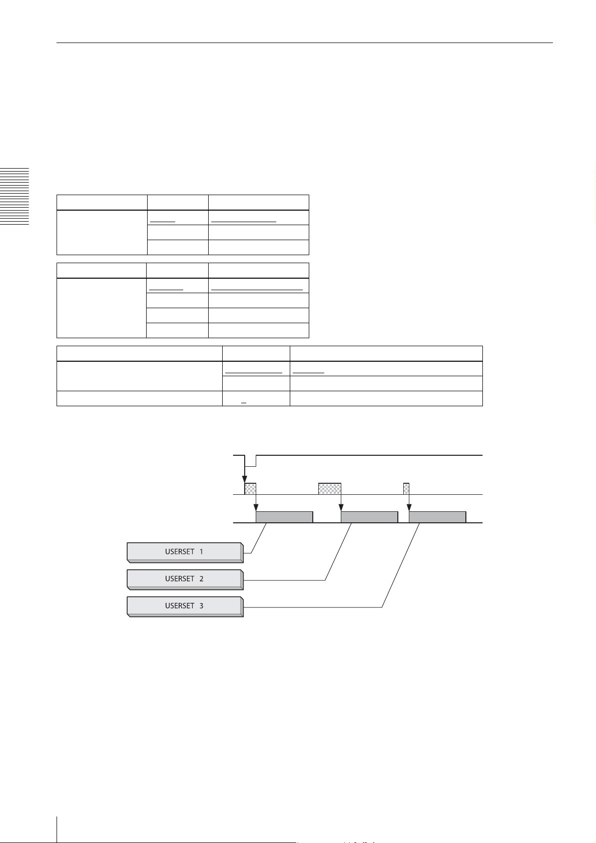
Bulk
SpecialTriggerSource=1, SpecialTriggerActivation=0, NumberOfMemoryForSpecialTriggerMode=3 in the figure.
Trigger signal
Exposure
Sensor output
Setting 1 Setting 2 Setting 3
20
Trigger Control
Page 21
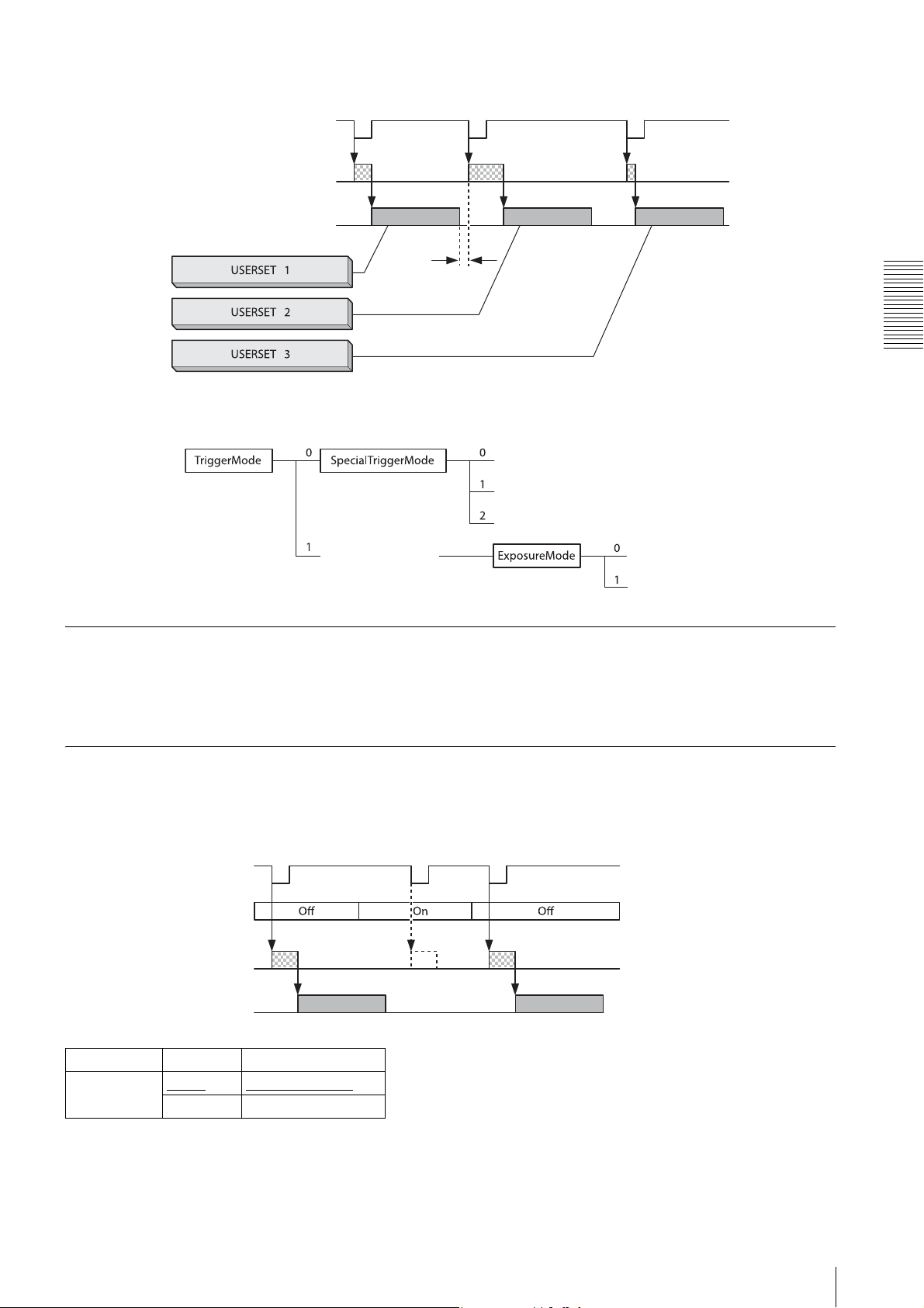
Sequential
SpecialTriggerMode=2, SpecialTriggerActivation=0 in the figure.
Trigger signal
Exposure
Trigger states
Trigger source
Sensor output
Setting 1 Setting 2 Setting 3
Trigger mode
5ms or
longer
Functions
Free run
Bulk
Sequential
Trigger edge detection
Trigger width detection
This can be input via the DC IN connector or software command (TriggerSoftware). Refer to “Trigger Signal Input”
(page 14) for details. Note that the trigger sources for the special trigger operation and the trigger mode operation are
defined separately.
Trigger inhibition
Trigger input can be disabled. This function is effective when disabling the trigger signal to a specific camera in the
environment where multiple cameras are connected by the same trigger signal and when preventing false operations
caused by noise contamination to the trigger signal line (due to the installed environment).
Trigger signal
Trigger inhibition
Trigger
Exposure
Sensor output
Register Parameter Setting
TriggerInhibit Off (0)
On (1) Trigger is not accepted
Trigger is accepted
disabled
Trigger Control
21
Page 22
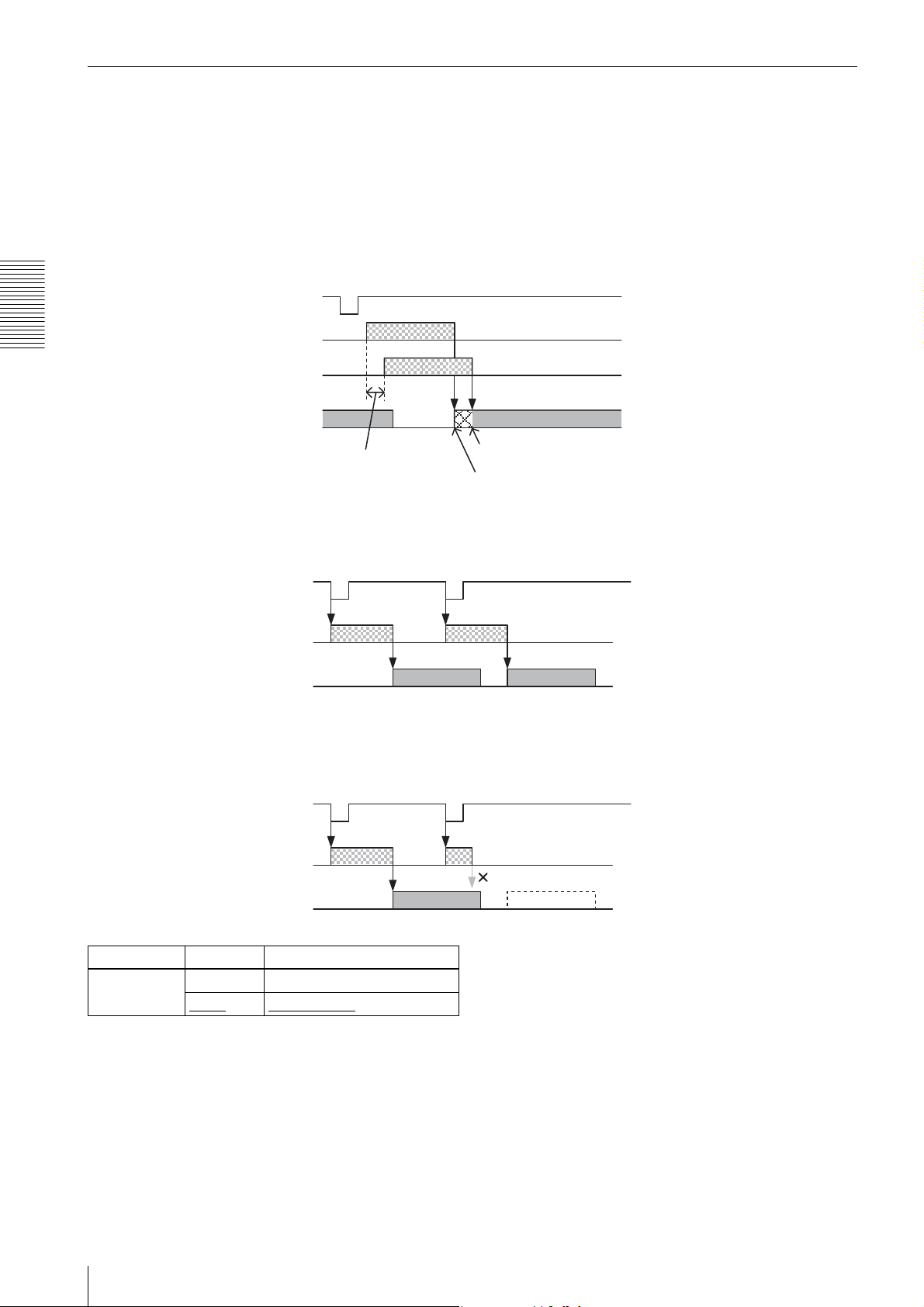
Trigger shift
This device can accept exposure by the next trigger even while a video is output (except for the special trigger
operation). In this case, trigger shift should be enabled since the trigger signal can become a noise source. When trigger
shift is enabled, adjustment is made automatically for operations from trigger input to exposure to prevent noise
contamination. Therefore, the time from trigger input to exposure start will be delayed up to 1 line. When disabling
trigger shift, this delay adjustment is not made and exposure is started consistently at the constant timing but noise may
occur in the image. Even when the trigger shift is enabled, the next video cannot be output before completing video
output and the trigger is disabled. Therefore, the exposure time setting (in the trigger edge operation), the effective
period of the trigger signal width to be input (in the trigger width operation), or the trigger interval should be sufficiently
long.
Trigger signal
Exposure
(Trigger shift off)
Functions
Exposure
(Trigger shift on)
Sensor output
Trigger shift max 1H
in this interval
Timing of trigger shift on
when delay is maximum
Timing of trigger shift off
When the next image can be output
Since video output is completed after the exposure is finished, the next video output can be started.
Trigger signal
The next image output is started after
Exposure
Sensor output
completing the previous image output.
When the next image cannot be output (double exposure)
Since video output is not completed after the exposure is finished, the next video output cannot be started. The input
trigger becomes invalid.
Trigger signal
The next image output is started before
Exposure
completing the previous image output.
Sensor output
Register Parameter Setting
TriggerShift Off (0) Trigger shift off
Trigger shift on
22
On (1)
Trigger Control
No image output
Page 23
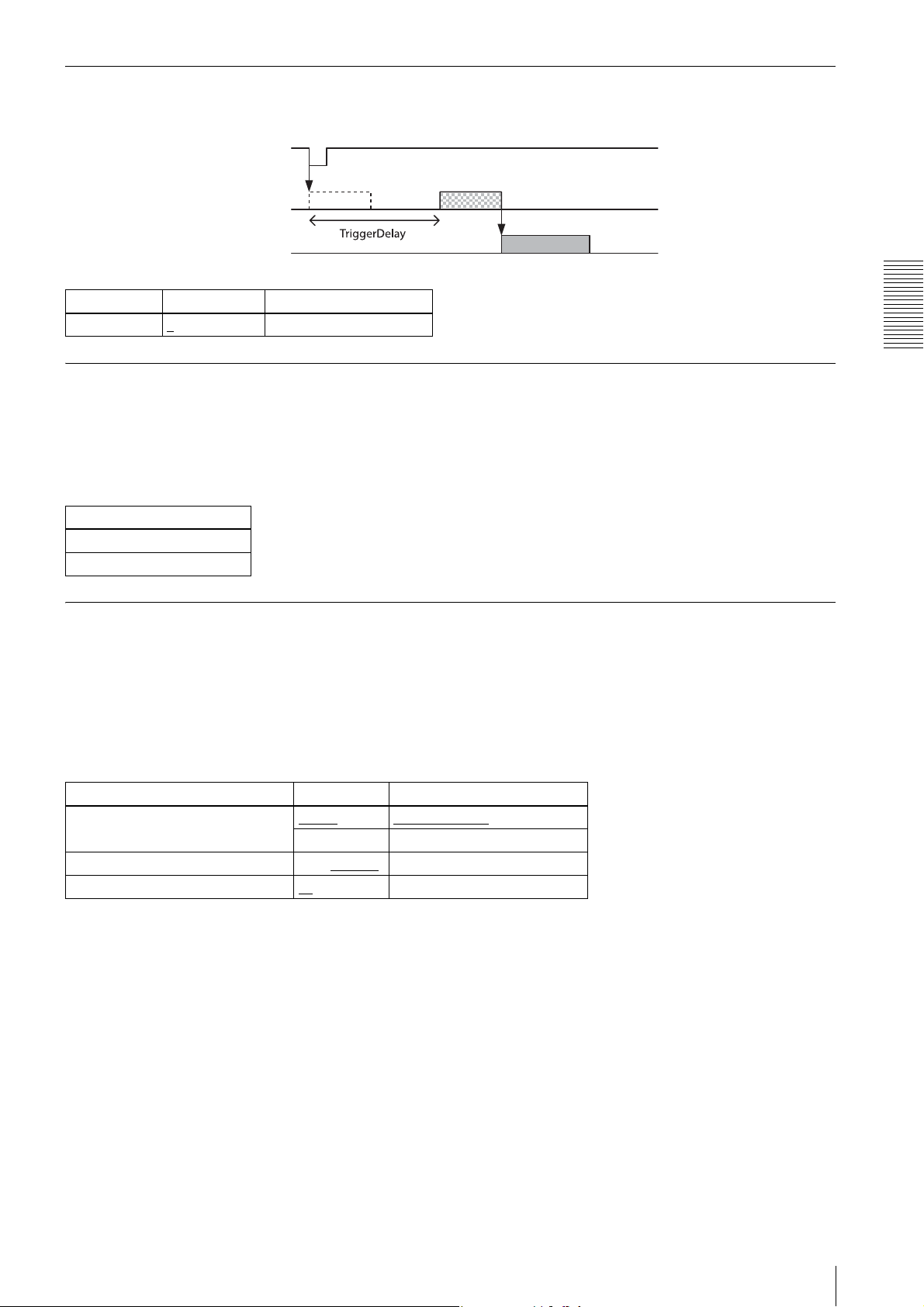
Trigg er delay
The camera can delay the trigger signal.
Trigger signal
Exposure
Sensor output
Register Parameter Setting
TriggerDelay 0
to 4000000 Trigger delay [µs]
Trigger counter
Accepted triggers by which video output is performed are counted. Triggers are counted up by the internal counter even
in the free-run operation. Setting 0 resets the counter. Video output is not performed for triggers that coincide with the
double exposure timing, but triggers are counted up. Triggers that have been removed by trigger range limit are not
counted. The trigger counter returns to 0 when the upper limit (2147483647) is reached. The trigger counter can return
to 0 by writing 1 to the TriggerCounterReset register.
Register
TriggerCounter
TriggerCounterReset
Functions
Trigger range limit
Only signals in the set trigger width can be accepted as the trigger signal. This functions as a noise filter, which removes
chattering or disturbance noise in the trigger signal line. This also functions as a trigger selector, whereby only a specific
camera can be operated by the trigger when multiple cameras share one trigger signal line. When the trigger signal is
input, exposure is started immediately to increment the trigger counter; however, when trigger width is out of the range,
video is not output and the trigger counter is decremented. If the shutter time is set shorter than the upper limit, triggers
will be received and video is output even if the trigger signal is wider than the trigger range limit. If the trigger source
is soft trigger, trigger range is not enabled.
Register Parameter Setting
TriggerAcceptanceRangeEnabled Off (0)
On (1) Trigger range on
TriggerAcceptanceRangeUpperLimit 10 to 2000000
TriggerAcceptanceRangeLowerLimit 10
to 2000000 Trigger range lower limit [µs]
Trigger range off
Trigger range upper limit [µs]
Trigger Control
23
Page 24
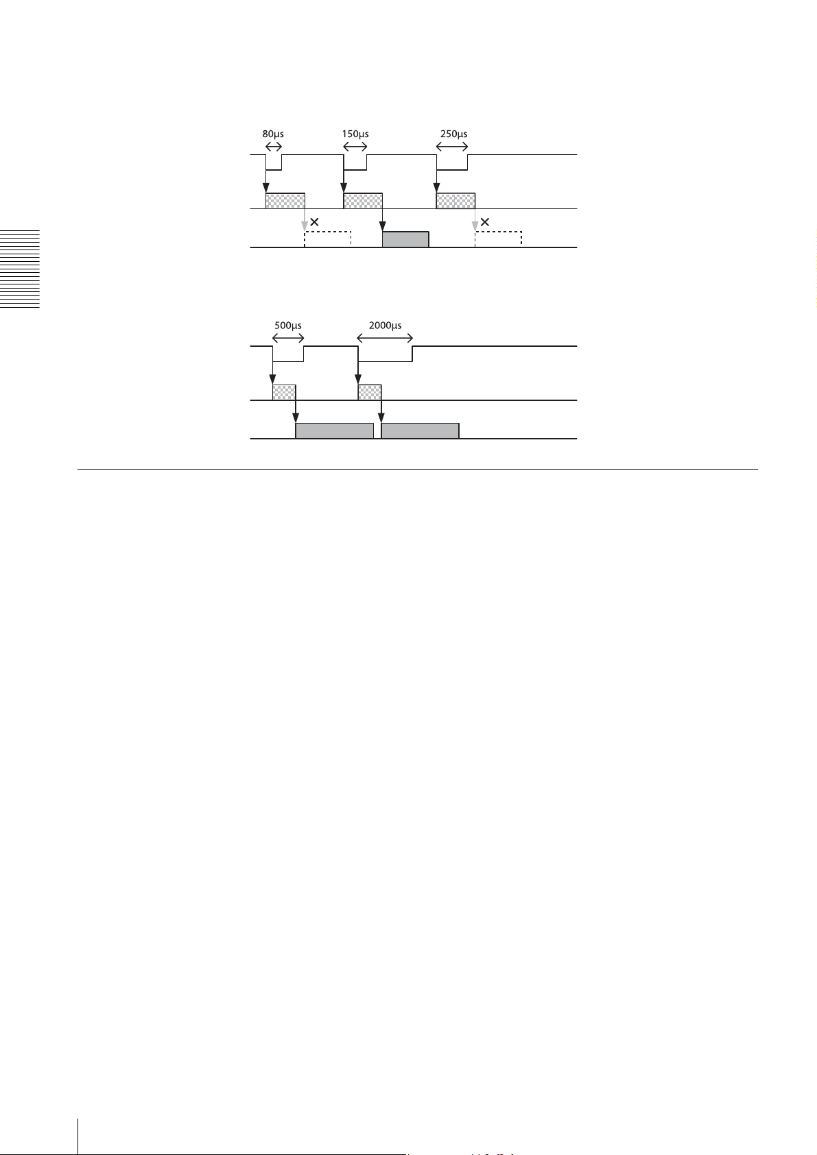
Trigger range operation example
ExposureTime=300, TriggerAcceptanceRangeLowerLimit=100, TriggerAcceptanceRangeUpperLimit=200 in the
figure.
Trigger signal
Exposure
Sensor output
ExposureTime=300, TriggerAcceptanceRangeLowerLimit=100, TriggerAcceptanceRangeUpperLimit=1000 in the
figure.
Functions
Trigger signal
Trigger not disabled
Exposure
Sensor output
Trigger control
Since detection of the trigger width time requires a certain time during the trigger width detection operation, the
exposure time will be slightly longer than the input trigger width time. To perfectly match with the trigger signal width
period, TriggerControl should be set to 0. TriggerShift=1 and TriggerControl=0 cannot be set at the same time. Refer
to “Trigger latency” (page 28) for details.
24
Trigger Control
Page 25
Frame Rate
Auto frame rate
The reading cycle is set to allow the frame rate to be the maximum value automatically according to the current shutter
setting and the partial scan setting in the free-run operation (Shutter has priority). The next exposure is performed while
outputting a video and the next video output is started immediately after finishing all video outputs. The frame rate is
lowered when setting the shutter time longer than the video output time.
Register Parameter Setting
AcquisitionFrameRateAuto Off (0) Auto frame rate off
On (1)
Specifying frame rate
The frame rate of the video output can be specified in the free-run operation. The value of the frame rate [fps] should
be entered. The frame rate faster than the fastest frame rate cannot be set.
Register Parameter Setting
AcquisitionFrameRate 0.0625 to 2000 Frame rate [fps]
* The upper limit varies depending on the partial scan setting.
Auto frame rate on
Functions
Displaying frame rate
The current frame rate during the auto frame rate operation is displayed.
Register
AcquisitionFrameRateActual
Frame Ra te
25
Page 26
Fastest frame rate for partial scanning
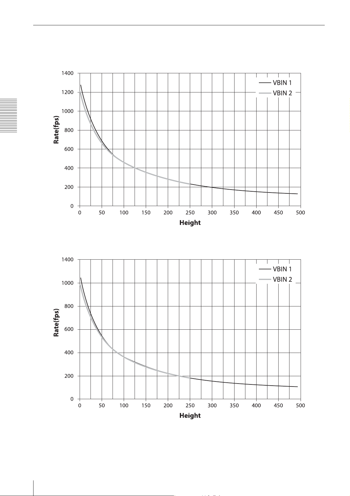
The fastest frame rate varies depending on Height for partial scanning.
XCG-C30/C
Functions
XCG-C32/C
26
Frame Rate
Page 27
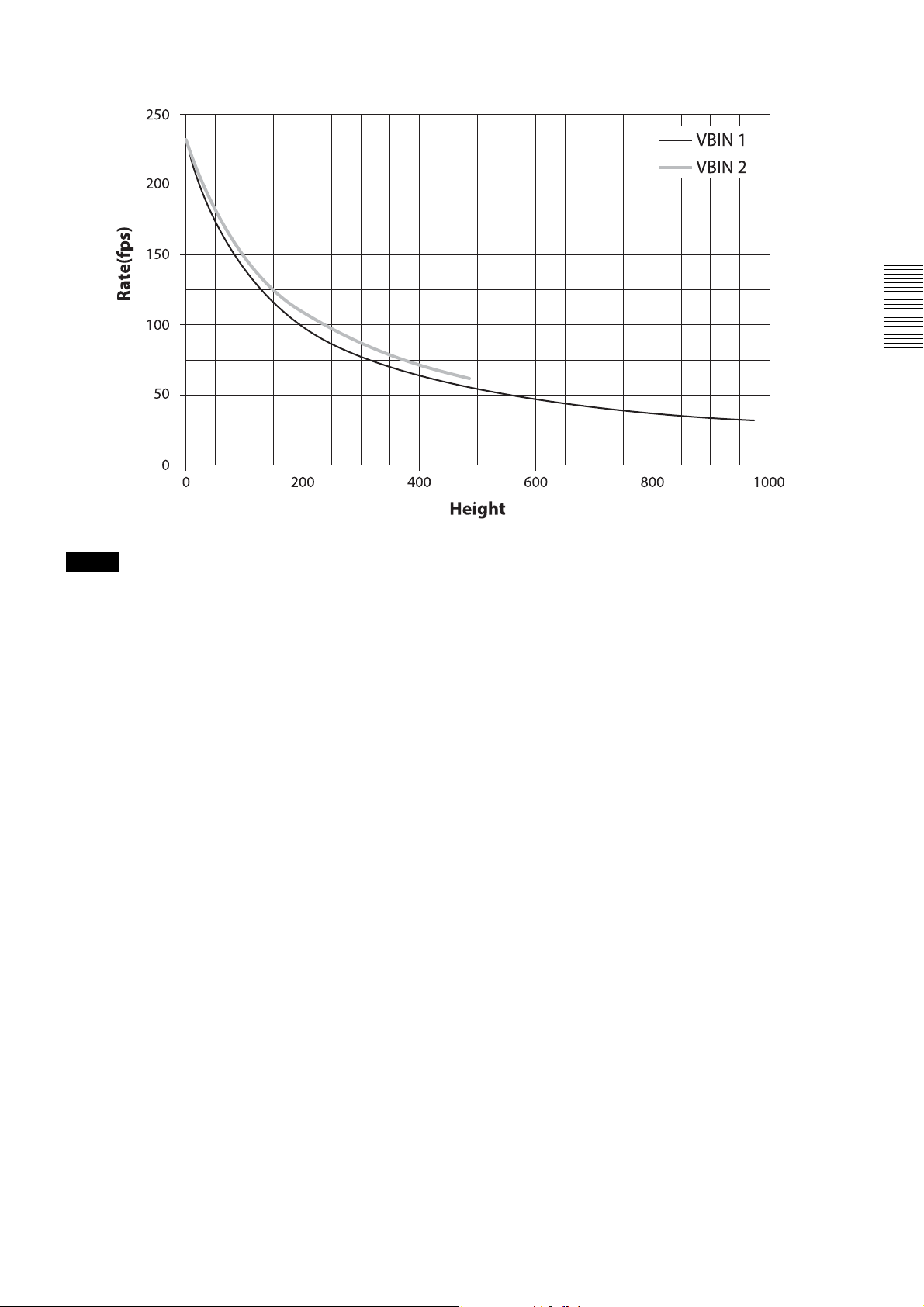
XCG-C130/C
Functions
Note
The VBIN=2 setting is not available on color models.
Frame Ra te
27
Page 28
Timing Chart
Trigg er late ncy
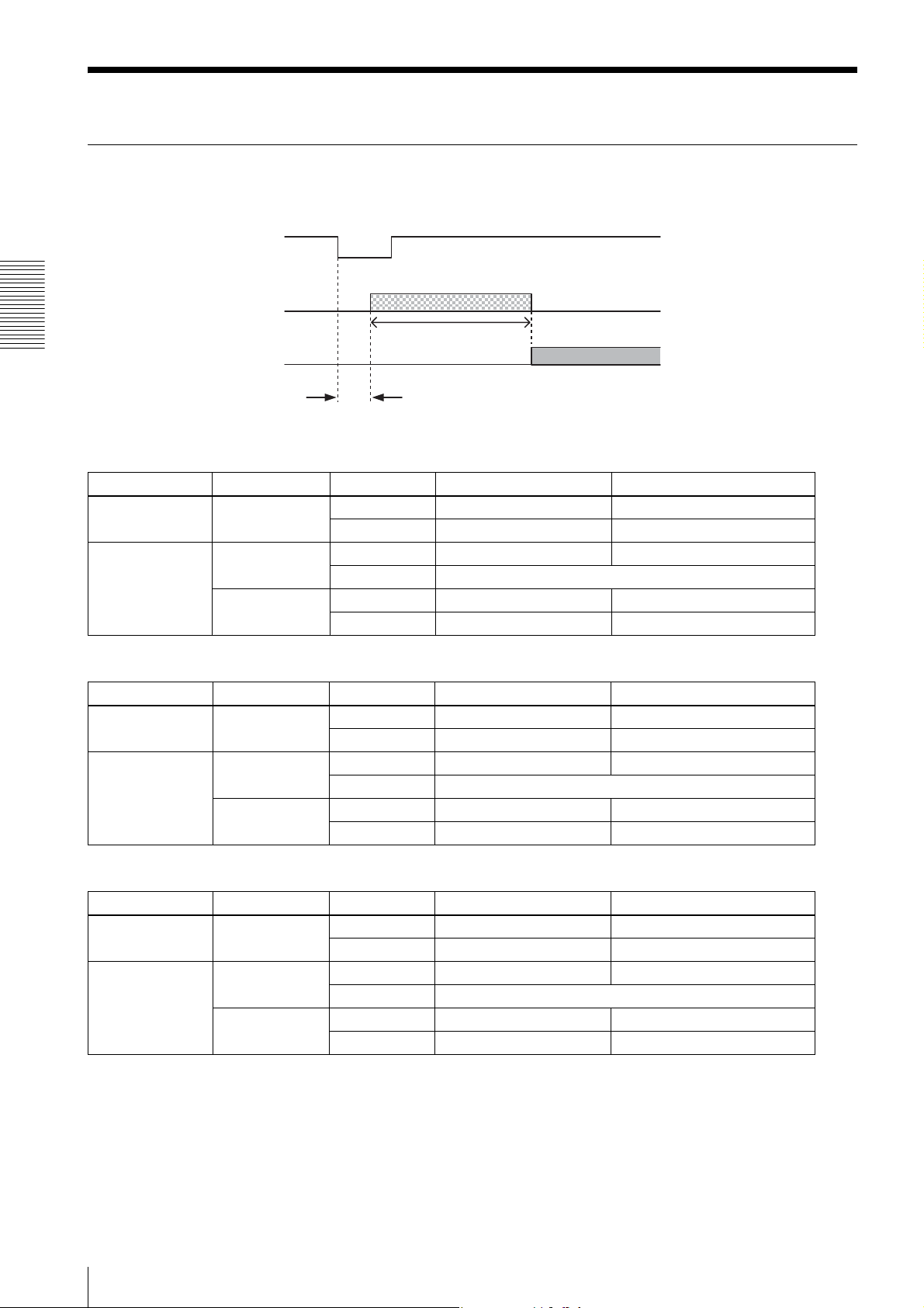
The time from the trigger acceptance to the exposure start (trigger latency) varies depending on various conditions. In
the trigger width detection operation, the value is changed by TriggerControl.
Trigger signal
Exposure
Exposure time
0
1
Sensor output
Trigger latency
0 Approx. 0.7 µs ExposureTime
1 Approx. 0.7 µs to 16.3 µs ExposureTime
0 0 Approx. 6.9 µs ExposureTime
1 Cannot be set*
1 0 Approx. 2.2 µs ExposureTime + approx. 5 µs
1 Approx. 2.2 µs to 18.8 µs ExposureTime + approx. 5 µs
Functions
XCG-C30/C
ExposureMode TriggerControl TriggerShift Trigger latency Exposure time
(edge detection)
(width detection)
XCG-C32/C
ExposureMode TriggerControl TriggerShift Trigger latency Exposure time
0
(edge detection)
1
(width detection)
0 0 Approx. 8.7 µs ExposureTime
1 0 Approx. 2.8 µs ExposureTime + approx. 6 µs
0 Approx. 0.8 µs ExposureTime
1 Approx. 0.8 µs to 20.3 µs ExposureTime
1Cannot be set*
1 Approx. 2.8 µs to 22.3 µs ExposureTime + approx. 6 µs
XCG-C130/C
ExposureMode TriggerControl TriggerShift Trigger latency Exposure time
0
(edge detection)
1
(width detection)
0 0 Approx. 14.2 µs ExposureTime
1 0 Approx. 2.4 µs ExposureTime + approx. 12 µs
0 Approx. 1.4 µs ExposureTime
1 Approx. 1.4 µs to 34.6 µs ExposureTime
1Cannot be set*
1 Approx. 2.4 µs to 35.6 µs ExposureTime + approx. 12 µs
* TriggerControl=0 and TriggerShift=1 cannot be set at the same time.
The settings will be discarded, and TriggerControl=1 and TriggerShift=1 will be used.
28
Timing Chart
Page 29
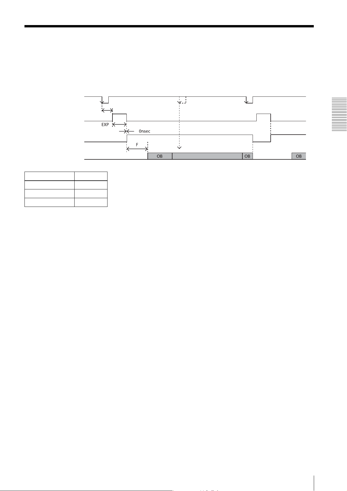
Sensor Readout (Sensor Output)
This signal indicates that exposure has completed and the CCD has entered the video output sequence, Output is
available from the GPO1, 2 or 3 terminals. The sensor readout signal is asserted before optical black and the effective
pixel area is output. If the following trigger signal is input when this signal is asserted, horizontal line noise may occur
in an image. The trigger shift function (page 22) can effectively prevent noise contamination.
The time required for the CCD to start OB (optical black) and effective pixel output after sensor readout signal assertion
is shown below. OB is not output from a camera.
Trigger signal
Trigger latency
Exposure signal
When a trigger signal is input,
noise may occur in an image.
Sensor readout signal
(Sensor output)
CCD video output
F
XCG-C30/C 32 µs*
XCG-C32/C 40 µs*
XCG-C130/C 60 µs
* When VBIN=2, increase of approximately 3 µs.
**When OFFSETX= 0, OFFSETY= 0, shortest value.
Functions
Effective pixel
Sensor Readout (Sensor Output)
29
Page 30
White Balance
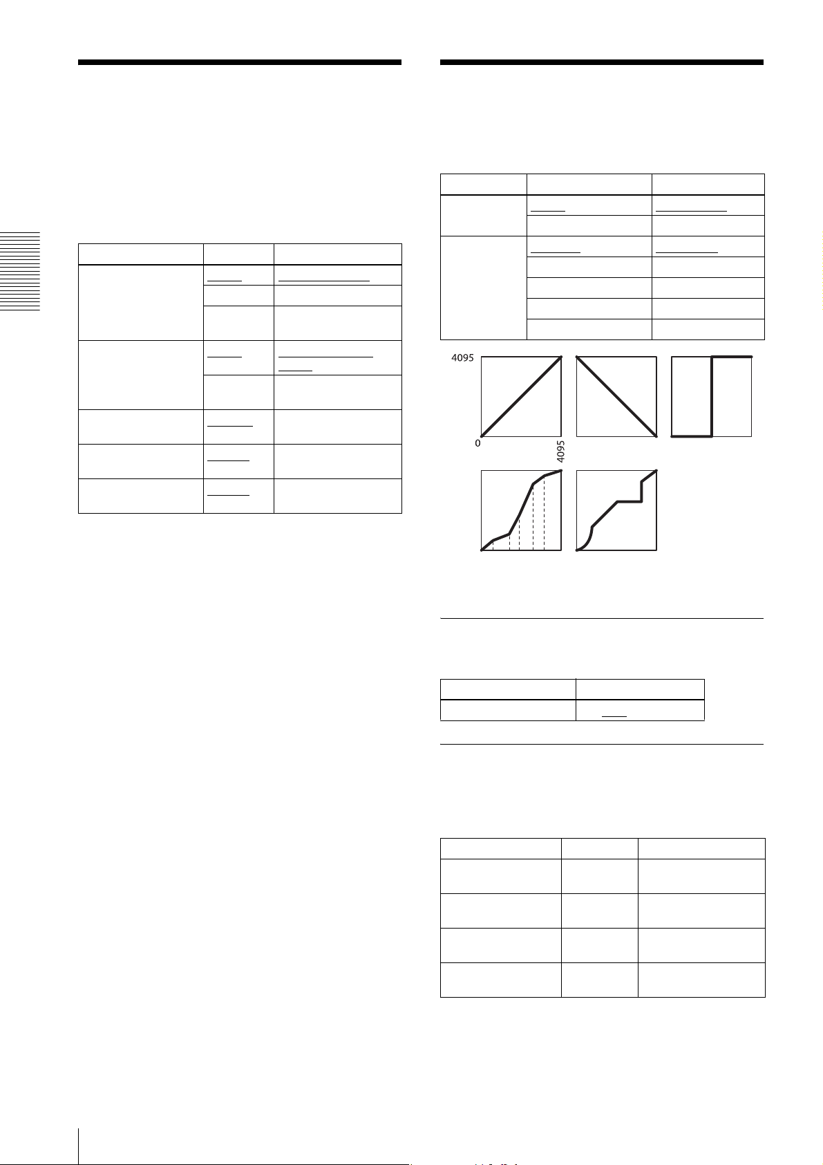
LUT
The white balance can be automatically adjusted when
the BalanceWhiteAuto command is executed. The
detection area is set to the screen center by default. The
Five types of presets are provided. Specify using a 12 bit
value. Binarization, 5-point interpolation, and arbitrary
setting can be changed.
detection area can also be displayed on the screen. The
detection frame can be changed arbitrarily
(DetectAreaWBAuto). For manual correction, the
GainDigital should be executed.
Register Parameter Setting
BalanceWhiteAuto Off (0)
Once (1) One-push AWB
Functions
DetectAreaGainAuto Off (0) Detection frame is
GainDigitalRedRaw 256 (x1)
GainDigitalGreenRaw 256 (x1)
GainDigitalBlueRaw 256 (x1)
Continuous
(2)
On (1) Detection frame is
4096
4096
4096
Manual correction
Continuous AWB
hidden
displayed
to
Red gain
to
Green gain
to
Blue gain
Register Parameter Setting
LUTEnable Off (0)
On (1) LUT on
LUTFormat Linear (0)
Reverse (1) Reverse
Binarization (2) Binarization
LinearInterpolation (3) 5-point interpolation
UserSet (4) Arbitrary setting
1. LUT off 2. Reverse 3. Binarization
LUT off (γ=1)
Linear (γ=1)
4. 5-point
interpolation
5. Arbitrary setting
Binarization
The binarization threshold can be changed.
Register Parameter
BinarizationThreshold 0 to 2047
to 4096
5-point interpolation
The values of output points 1 through 5 that correspond
to input points 1 through 5 can be changed. Linear
interpolation is performed between interpolation points.
Register Parameter Setting
LinearInterpolationIndex
LinearInterpolationInValue
LinearInterpolationOutValue
LinearInterpolationBuild
Index1(1) to
Index(5)
0 to 4095 Input
0 to 4095 Output
Select the interpolation
points
Build LUT
30
White Balance
Page 31
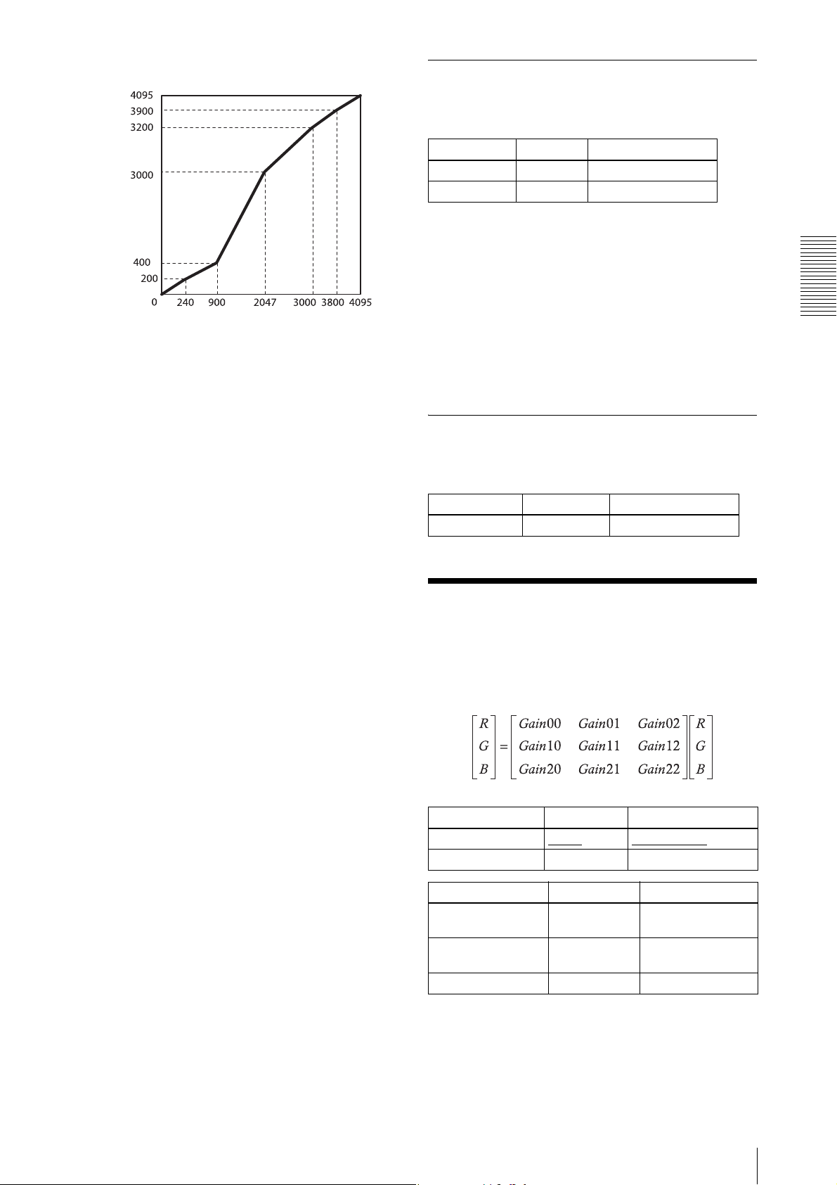
Setting example:
Output
LinearInterpolationIndex = 1
LinearInterpolationInValue = 240
LinearInterpolationOutValue = 200
LinearInterpolationIndex = 2
LinearInterpolationInValue = 900
LinearInterpolationOutValue = 400
LinearInterpolationIndex = 3
LinearInterpolationInValue = 2047
LinearInterpolationOutValue = 3000
LinearInterpolationIndex = 4
LinearInterpolationInValue = 3000
LinearInterpolationOutValue = 3200
LinearInterpolationIndex = 5
LinearInterpolationInValue = 3800
LinearInterpolationOutValue = 3900
LinearInterpolationBuild
Input
Arbitrary setting
The output values 0 through 4095 that correspond to
input values 0 through 4095 can be changed.
Register Parameter Setting
LUTIndex 0 to 4095 Input
LUTValue 0 to 4095 Output
Setting example:
LUTIndex = 0
LUTValue = 3
LUTIndex = 1
LUTValue = 10
…
LUTIndex = 4094
LUTValue = 4000
LUTIndex = 4095
LUTValue = 4010
Save LUT
When you change the settings, save them using the LUTSAVE command.
Register Parameter Setting
LUTValueSave Save LUT
Color Matrix Conversion
During RGB 24-bit, YUV 24-bit, and YUV 16-bit
output, the following color matrix conversion can be
applied to the color model. Specify using values
between –8191 and +8191. 256 is ×1.
Functions
Register Parameter Setting
ColorMatrixEnable On (0)
Off (1) Conversion on
Register Parameter Setting
ColorMatrixSelectorRow
ColorMatrixSelectorColumn
ColorMatrixValue
0 to 2 Matrix row position
0 to 2 Matrix column
–8191 to 8191 Gain value
Conversion off
position
Color Matrix Conversion
31
Page 32
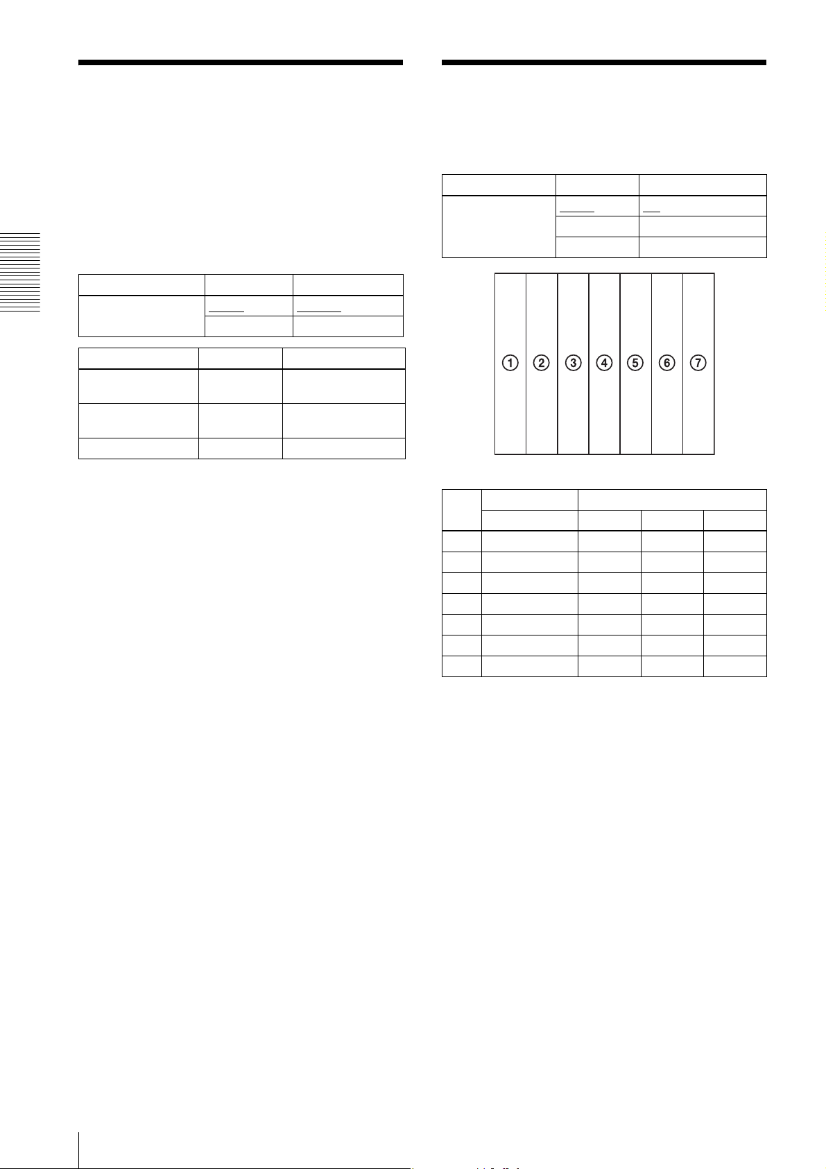
3 × 3 filter
Test Chart Output
Monochrome model and color model apply a 3 × 3 area
filter for RAW output. The brightness of the central pixel
and the eight pixels around it, and the parameter of each
For monochrome model, monochrome chart can be set.
For color model, monochrome chart or color chart can
be set.
pixel are multiplied and added together, The result is the
brightness of the central pixels. Specify using values
between -8191 and 8191. The parameter 256 is ×1.
Depending on the patterns of parameters, you can
reduce noise, apply edge enhancement and extract the
contour.
Register Parameter Setting
Functions
SpatialFilterEnable Off (0)
On (1) Filter on
Register Parameter Setting
SpatialFilterSelectorRow
SpatialFilterSelectorColumn
SpatialFilterValue
0 to 2 Matrix row position
0 to 2 Matrix column
–8191 to 8191 Filter parameters
Filter off
position
Register Parameter Setting
TestImageSelector Off (0)
GrayBar (1) Monochrome chart
ColorBar (2) Color chart
Monochrome Color
Raw/Mono R G B
(1) 0xF30 0x3FF 0x3FF 0x3FF
(2) 0xDC0 0x3FF 0x3FF 0
(3) 0xC80 0 0x3FF 0x3FF
(4) 0xA00 0 0x3FF 0
(5) 0x7A0 0x3FF 0 0x3FF
(6) 0x550 0x3FF 0 0
(7) 0x340 0 0 0x3FF
Off
* 12 bit notation
32
3 × 3 filter
Page 33
GPIO
GPI
The signal level which is input in the 2nd, 3rd, and 4th
DC IN connector can be detected. After selecting a
connector by LineSelector register, the signal level is
acquired from LineStatus register.
GPO
Various signals can be output from the 3rd and 4th DC
IN connector. After selecting a connector by
LineSelector register and setting LineMode to Output,
LineSource is set. The output polarity is set by
LineInverter register.
Register Parameter Setting
LineSelector Line1 (0) DC IN connector 2nd pin
Line2 (1) DC IN connector 3rd pin
Line3 (2) DC IN connector 4th pin
LineMode Input (0) Set to output
Output (1) Input setting
LineInverter Off (0) Without output inversion
On (1) With output inversion
LineStatus Input signal level
LineSource TriggerThrough (0) Trigger through signal
ExposureActive (2) Exposure signal
StrobeActive (3) Strobe control signal
SensorReadout (4) Sensor readout signal
UserOutput1 (5) User definition 1
UserOutput2 (6) User definition 2
UserOutput3 (7) User definition 3
SignalTrue (8) Level H
SignalFalse (9) Level L
PWM (10) Pulse generation signal
Functions
Setting example:
The strobe control signal is output to GPO2 (DC IN
connector 3rd pin) by Hi active setting.
LineSelector = 1
LineMode = 1
LineInverter = 0
LineSource = 3
GPIO
33
Page 34
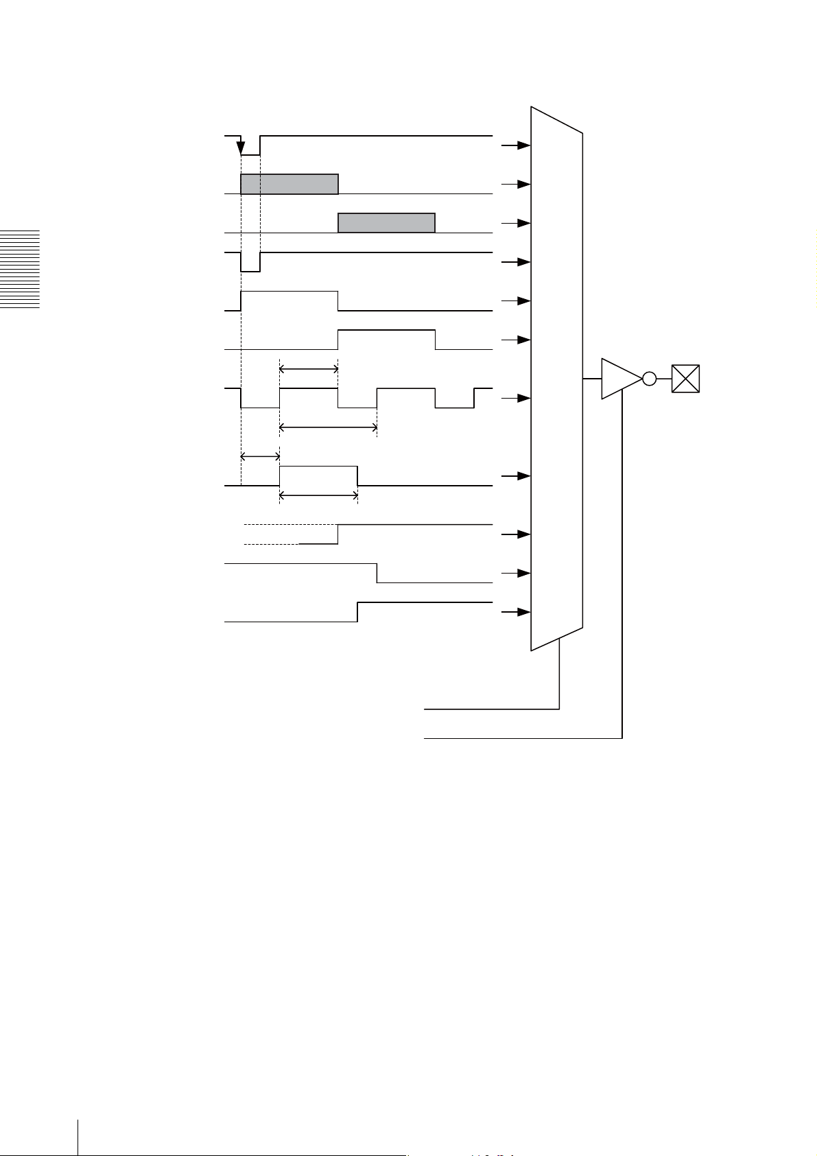
GPO output system diagram (example of
GPO1)
Trigger signal
Exposure
Sensor output
Trigger through signal
Exposure signal
Functions
Sensor readout signal
GPO2
Pulse signal
Strobe control signal
(GPO1)
StrobeActiveDelay
StrobeActiveTime
GPO3
User definition 1
User definition 2
User definition 3
1
0
LineSource
LineInverter
34
GPIO
Page 35
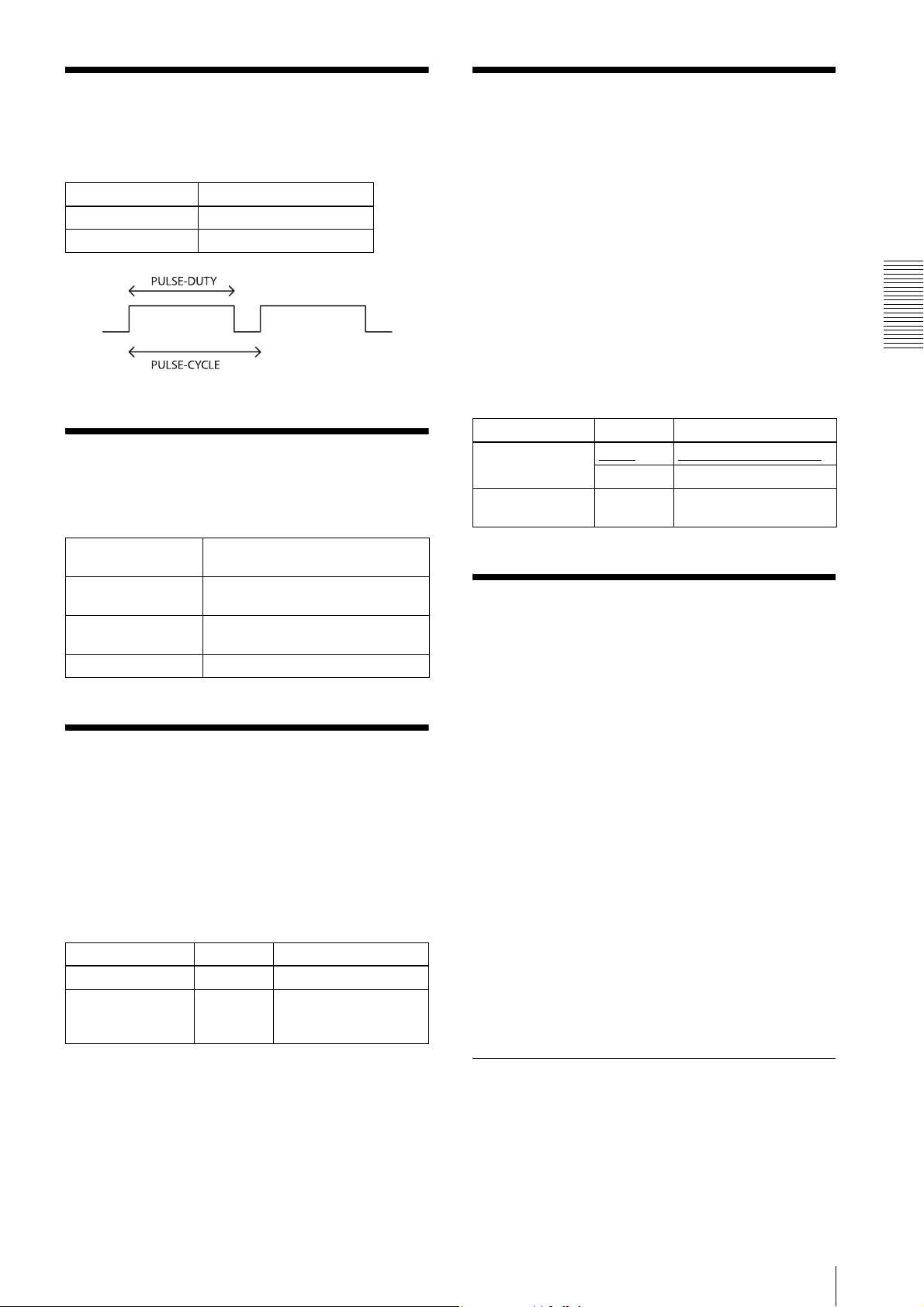
Pulse Train Generator
Sensitivity Control
Pulse waveforms can be output from the GPO2/3
connector. Available range is 0.5Hz to 100kHz.
Register Parameter
PWMPulseDutyT 1 to 2000000 [µs]
PWMPulseCycleT 10 to 2000000 [µs]
Status LED
The LED-on, blinking, or LED-off condition of the LED
on the rear panel is as follows:
LED-on Power is turned on and an IP address is
set.
Blinking (low speed) Power is turned on and an IP address is
not set.
Blinking (high speed) Power is turned on and the reset button
is pressed down.
LED-off Power is turned off or during startup.
The VSUB (substrate bias voltage) in the CCD can be
changed*
Qs (saturation signal charge) value. Increasing the
VSUB has the effect of improving the sensitivity*
Therefore, when capturing a dark image but the
exposure time cannot be extended, this has the effect of
improving the image quality. On the other hand,
decreasing the VSUB has the effect of reducing image
smearing. The factory setting is adjusted to the optimal
value.
1
*
2
*
VsubExternalMode On (0)
VsubExternalValue 0 to 127 Sensitivity adjustment
1
. VSUB adjustment allows you to change the
2
.
Not including XCG-C130 and XCG-C130C
If Qs exceeds the maximum signal charge amount
that can be transferred vertically and horizontally, a
transfer error will occur, resulting in image smearing,
etc.
Register Parameter Setting
Sensitivity adjustment off
Off (1) Sensitivity adjustment on
value
User Set
Main set values can be saved to the channels 1 to 16 of
USERSET. Refer to “Command List” (page 37) for
items to be saved. The factory setting is saved to channel
0, which cannot be overwritten.
Functions
Temperature Readout Function
The camera’s internal temperature can be read from the
temperature sensor installed in the circuit board. Its
accuracy is ±2°C. Use this value as a general guide.
If the interval of the temperature sensor value is set to a
value other than 0, the temperature information can be
transmitted to a PC application as an event data.
Register Parameter Setting
CameraTemperature Temperature sensor value
CameraTemperatureMeasurementInterval
32-bit
integers
Update interval of the
temperature sensor value
[second]
Setting example (1):
Shutter is 3 ms, Gain is 3 dB, Pulse signal is output to
GPO3 connector (this setting is saved to the channel
1).
ExposureTime=3000
Gain=3
LineSelector=Line3
LineMode=Output
LineSource=PWM
UserSetSelector=1
UserSetSave
Setting example (2):
The user set saved in the channel 2 is loaded.
UserSetSelector=2
UserSetLoad
User set memory
This is one of the items to be saved in the user set
channel. Signed 32-bit numbers are assigned to slots 0 to
15.
Pulse Train Generator
35
Page 36
User ID
Restart
User IDs are unique names that can be assigned to
cameras. A string that is 15 characters long can be
assigned.
Register Parameter
DeviceUserID 15 characters of your choice
The camera is rebooted.
Register
CameraReboot
Switching a CCD Driving
Saving and Startup
Functions
The startup setting can be determined by
UserSetDefaultSelector. This is also used to check
which user set settings are currently being used.
Usage example:
Startup with the setting saved in the user set channel 3.
UserSetDefaultSelector=3
(Restart or CameraReboot command)
Check which user set settings are the current settings.
Read UserSetDefaultSelector
Clock
This is a function that reduces power consumption by
decreasing a CCD driving clock. The frame rate of the
image output becomes low.
The rate between the normal mode and the low speed
mode of the clock speed is as follows.
For example:
The frame rate of XCG-C30 in normal mode is 130 fps
and in low speed mode is 31 fps (12/50 times of the
normal mode). Operation in the low speed mode can
reduce power consumption of maximum approx. 20 %
compared to the operation in the normal mode.
(The rate changes depending on the operating
conditions.)
Camera Information
The model name of a camera or its firmware information
can be read out.
Register Read out items
DeviceVendorName Manufacture name (SONY)
DeviceModelName Model name
DeviceVersion Firmware version
DeviceSerialNumber Serial number
DeviceManufacturerInfo Data for service
Normal mode Low speed mode
XCG-C30/C 50 12
XCG-C32/C 40 10
XCG-C130/C 50 12
Register Parameter Setting
CameraSwitchPixelClock
Note
To switch between the normal mode and low speed
mode, turning on/off the power supply is required. After
the mode is changed, the change is reflected by turning
on/off the power supply.
Normal (0)
Low (1) Low speed mode
Normal mode
36
User ID
Page 37
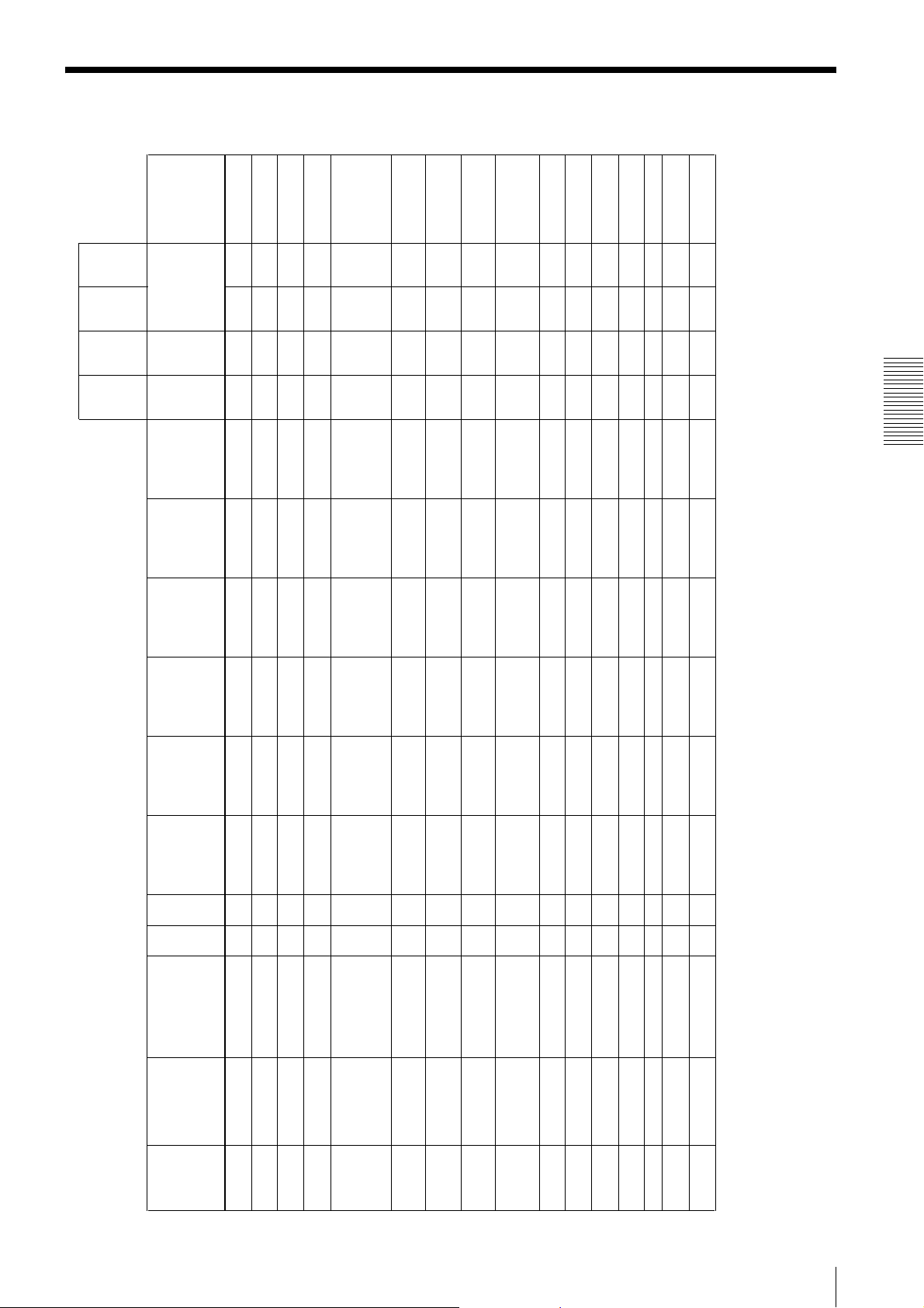
Command List
necessarily null-
terminated and
GEV2.0 is not
necessarily null-
terminated.
Initial iza-
tion by
pressing
the reset
button
for 3
seconds
When
rebooting
the
camera
or re-
turning
power on
are not retained in
the memory)
×: no change (items
are retained in the
memory)
-: no change (items
cannot be changed)
Items
that can
be loaded
from the
UserSet
(16
channels)
Items
that can
be saved
in the
UserSet
(16
channels)
--
multiples of 2.
multiples of 2.
multiples of 2.
multiples of 2.
--
--
× aaThe setting value is in
a × aaThe setting value is in
Command List
16 to (1280) to
Version
Version
Ver s i on
information
information
information
1296
1296
1 (readout is
disabled)
1 (readout is
disabled)
1 (readout is
disabled)
1 (readout is
disabled)
1 (readout is
disabled)
1 (readout is
disabled)
Version
information
Version
information
information
Write XCG-C30 XC G-C30C XCG-C32 XCG-C32C XCG-C130 XCG-C130C aaa: change (items
out
aa"" "" "" "" "" "" × a *0: GEV1.2 is
User-defined name
(16-byte string including
Network configuration aa666666 × a
Default gateway aa 000000 × a
Subnet mask aa000000 × a
Fixed IP address aa000000 × a
BOOTSTRAP_
Configuration
DefaultGateway
SubnetMask
IPAddress
a × "XCG-C30" "XCG-C30C" "XCG-C32" "XCG-C32C" "XCG-C130" "XCG-C130C" - -
Null-terminated
characters) *0
string including Null-
terminated character s)
DeviceUserID
a × Version
a × "SONY" "SONY" "SONY" "SONY" "SONY" "SONY" - -
Vendor name (32-byte
string including Null-
terminated character s)
Name
a × Vendor eigenvalue Vendor eigenvalue Vendor eigenvalue Vendor eigenvalue Vendor eigenvalue Vendor eigenvalue - -
including Null-terminated
characters)
Manufacturer information
(48-byte string including
Null-terminated
characters)
ManufacturerInfo
1 (readout is
disabled)
1 (readout is
disabled)
disabled)
1 (readout is
disabled)
1 (readout is
disabled)
disabled)
Address Model name Read-
0x064C GevPersistent
0x066C GevPersistent
0x065C GevPersistent
0x00E8 GEV_
0x0014 GevIP
0x0068 DeviceModelName Model name (32-byte
0x0048 DeviceVendor
0x0088 DeviceVersion Version (32-byte string
0xA000 Width Width of output image aa16 to (640) to 656 16 to (640) to 656 16 to (640) to 656 16 to (640) to 656 16 to (1280) to
0x00A8 Device
0xA004 Height Height of output image aa32 to (480) to 494 32 to (480) to 494 32 to (480) to 494 32 to (480) to 494 32 to (960) to 966 32 to (960) to 966 a
0xA008 OffsetX Output image OffsetX aa0 to (8) to 640 0 to (8) to 640 0 to (8) to 640 0 to (8) to 640 0 to (8) to 1280 0 to (8) to 1280 a × aaThe setting value is in
0xA00C OffsetY Output image OffsetY aa0 to (6) to 462 0 to (6) to 462 0 to (6) to 462 0 to (6) to 462 0 to (2) to 934 0 to (2) to 934 a × aaThe setting value is in
0xA010 AcquisitionMode Acquisition mode aa(0) / 1 / 3 (0) / 1 / 3 (0) / 1 / 3 (0) / 1 / 3 (0) / 1 / 3 (0) / 1 / 3 a × aa
0xA014 AcquisitionStart Starting image transfer × a 1 (readout is
0xA018 AcquisitionStop Stop image transfer × a 1 (readout is
Command List
37
Page 38
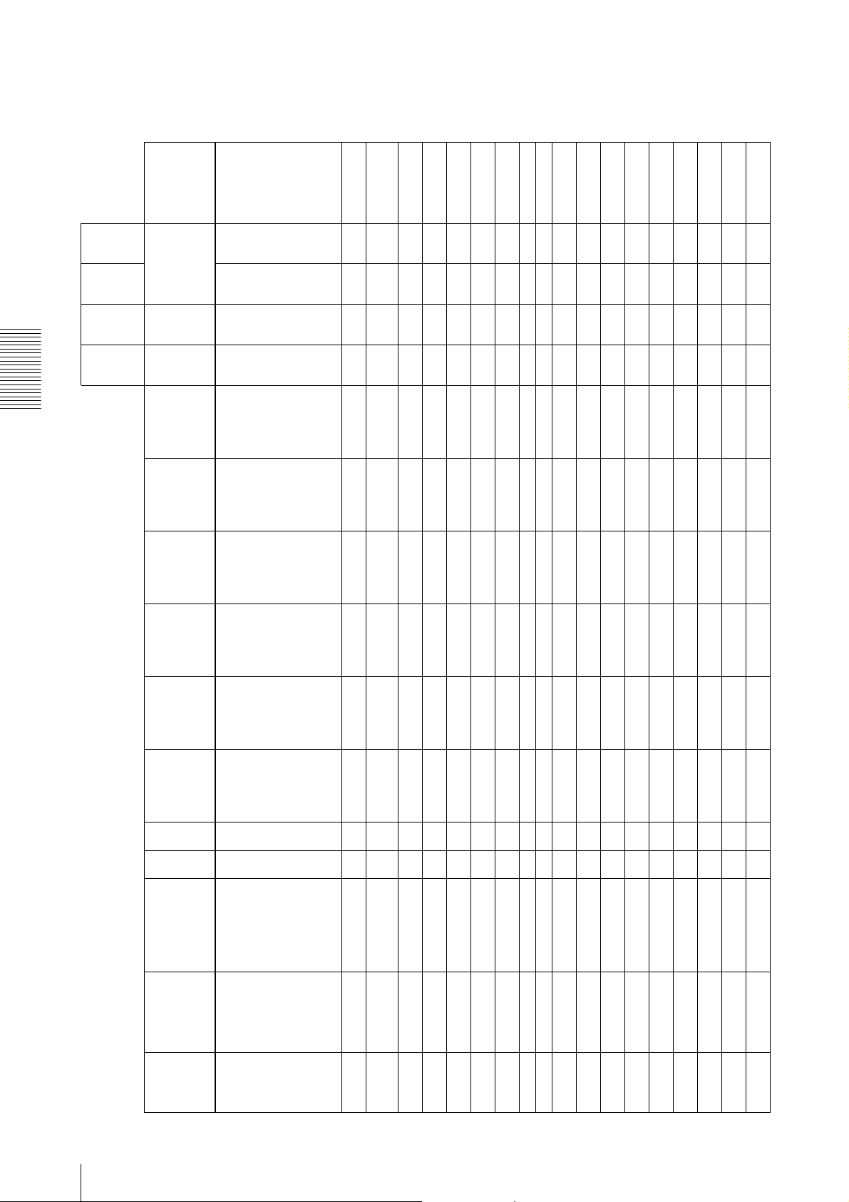
Initial iza-
tion by
pressing
the reset
button
for 3
seconds
When
rebooting
the
camera
or re-
turning
power on
are not retained in
the memory)
×: no change (items
are retained in the
memory)
-: no change (items
cannot be changed)
Items
that can
be loaded
from the
UserSet
(16
channels)
Items
that can
be saved
in the
UserSet
(16
channels)
a × aa
× a
aaaa
Command List
×(accessing is not
(0x01080009:
FRG8)
0x010C0027:
(0x01080001:
Mono8)
0x010C0004:
(0x01080009:
FRG8)
0x010C0027:
(0x01080001:
Mono8)
0x010C0004:
(0x00010002) /
RG10Packed
0x010C002B:
RG12Packed
0x02180014:
RGB8
0x0210001F:
YUV422_8_
UYVY
0x02180020:
YUV8_UYV
0x02100032:
YUV422_8
Mono10Packed
0x010C0006:
Mono12Packed
RG10Packed
0x010C002B:
RG12Packed
0x02180014:
RGB8
0x0210001F:
YUV422_8_
UYVY
0x02180020:
YUV8_UYV
0x02100032:
YUV422_8
Mono10Packed
0x010C0006:
Mono12Packed
0x00020000
(0x00010002) /
0x00020000
(0x00010002) /
0x00020000
(0x00010002) /
0x00020000
allowed)
allowed)
(0x00010002) /
(0x01080009:
FRG8)
0x010C0027:
RG10Packed
0x010C002B:
RG12Packed
0x02180014:
RGB8
0x0210001F:
YUV422_8_
UYVY
0x02180020:
YUV8_UYV
0x02100032:
YUV422_8
Mono8)
0x010C0004:
Mono10Packed
0x010C0006:
Mono12Packed
Write XCG-C30 XC G-C30C XCG-C32 XCG-C32C XCG-C130 XCG-C130C aaa: change (items
out
Address Model name Read-
0xA01C PixelFormat Pixel format aa(0x01080001:
a × -128 to +127 -128 to +127 -128 to +127 -128 to +127 -128 to +127 -128 to +127 - -
Readout device
tempera ture
Tem pera tur e
0xA0000014 Camera
0x00020000
0x00020000
aa- 1 to (50) to 100 - 1 to (50) to 100 - 1 to (50) to 100 aaaa
aa- 1 to (50) to 100 - 1 to (50) to 100 - 1 to (50) to 100 aaaa
aa- (0) / 1 - (0) / 1 - (0) / 1 aa
aa0 to (25) to 99 0 to (25) to 99 0 to (25) to 99 0 to (25) to 99 0 to (25) to 99 0 to ( 25) to 99 aaaa
aa(0) / 1 (0) / 1 (0) / 1 (0) / 1 (0) / 1 (0) / 1 × a
aa(0) - 0xFFFFFF FF (0) - 0xFFF FFFFF (0) - 0xFFF FFFFF (0) - 0x FFFFFFFF (0) - 0 xFFFFFFFF (0) - 0xFFFFFFFF × a
Temperature readout
interval
Measurement
0xA0000018 Camera-Temperature
a × (0) / 1 (0) / 1 (0) / 1 (0) / 1 (0) / 1 (0) / 1 - -
VsubExternal aa0 to (80) to 127 0 to (80) to 127 0 to (76) to 127 0 to (76) to 127 ×(accessing is not
VsubExternalMode aa(0) / 1(0) / 1(0) / 1(0) / 10 0 aaaa
Pixel clock frequency at
Switching of GEV1.2/2.0 aa(0x00010002) /
StartUp
Interval
0xA0000020 GevVesionFor
next startup
Current pixel clock
frequency
Val u e
Mode
FrenquencySelect
Frenquency
0xA0000054 VsubExternal
0xA0000050 VsubExternal
0xA000002C StartupPixelClock
0xA0000028 CurrentPixelClock
0xA0000114 BinningVertical Vertical binning aa(1) / 2 1 (1) / 2 1 (1) / 2 1 a × aa
aa1 to (50) to 100 1 to (50) to 100 1 to (50) to 100 1 to (50) to 100 1 to (50) to 100 1 to (50) to 100 aaaa
aa(0) / 1 (0) / 1 (0) / 1 (0) / 1 (0) / 1 (0) / 1 aa
Width of AGC/AE
AGC/AE detection frame
is highlighted
Auto
0xA0000138 DetectAreaGain
0xA0000118 BinningHorizontal Horizontal binning aa(1) / 2 1 (1) / 2 1 (1) / 2 1 a × aa
0xA0000134 DetectAreaGain
aa0 to (25) to 99 0 to (25) to 99 0 to (25) to 99 0 to (25) to 99 0 to (25) to 99 0 to ( 25) to 99 aaaa
aa1 to (50) to 100 1 to (50) to 100 1 to (50) to 100 1 to (50) to 100 1 to (50) to 100 1 to (50) to 100 aaaa
AGC/AE detection frame
X
Height of AGC/AE
detection frame
detection frame
AutoOffsetX
AutoHeight
AutoWidth
0xA0000140 DetectAreaGain
0xA000013C DetectAreaGain
AWB detection frame X aa- 0 to (25) to 99 - 0 to (25) to 99 - 0 to (25) to 99 aaaa
Height of AWB detection
frame
Width of AWB detection
frame
AWB detection frame is
highlighted
AGC/AE detection frame
Y
AreaOffsetX
AutoHeight
AutoWidth
Auto
AutoOffsetY
0xA0000160 BalanceWhiteAuto
0xA000015C DetectAreaWB
0xA0000158 DetectAreaWB
0xA0000154 DetectAreaWB
0xA0000144 DetectAreaGain
38
Command List
Page 39
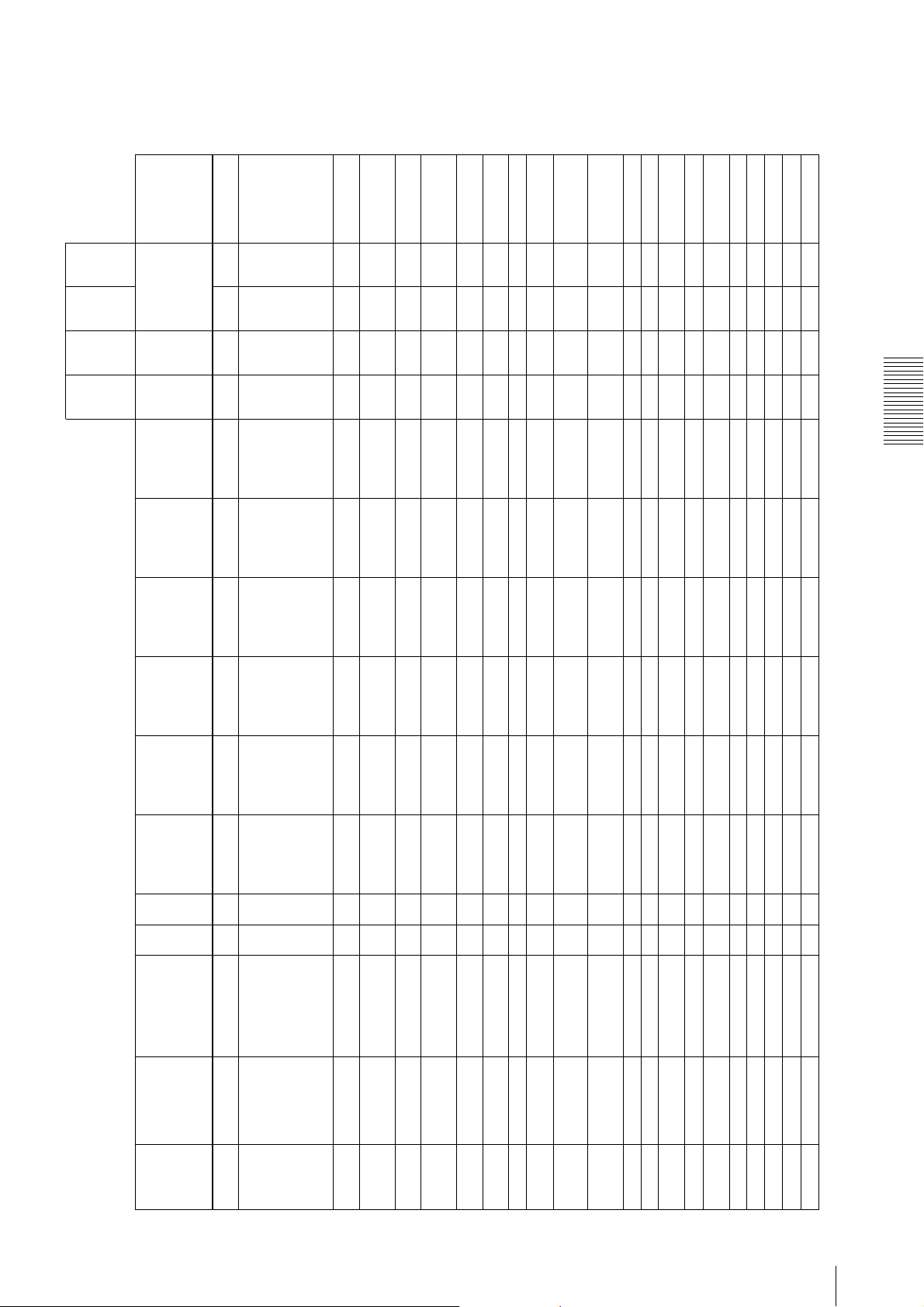
form with 32 bits is
used for this register,
so the valu e is like the
value of *1.
The value in
parentheses ( ) is
converted from the
above value into a
decimal number.
Initial iza-
tion by
pressing
the reset
button
for 3
seconds
When
rebooting
the
camera
or re-
turning
power on
are not retained in
the memory)
×: no change (items
are retained in the
memory)
-: no change (items
cannot be changed)
Items
that can
be loaded
from the
UserSet
(16
channels)
Items
that can
be saved
in the
UserSet
(16
channels)
aaaa*1: Floating point
aaaa
Command List
0x41F86E23
(31.053777694702
0x41F80000
(31.0) *1
0x41F80000
(31.0) *1
0x42D00000
(104.0) *1
0x42D00000
(104.0) *1
0x43020000
(130.0) *1
148) *1
0x41F86E23
(31.053777694702
148) *1
0x42D02599
(104.07343292236
328) *1
0x42D02599
(104.07343292236
328) *1
0x43020BB8
(130.04577636718
75) *1
1 to (32169) to
60000000
1 to (32169) to
60000000
1 to (9593) to
60000000
1 to (9593) to
60000000
1 to (7674) to
60000000
(130.04577636718
(130.0) *1
Write XCG-C30 XC G-C30C XCG-C32 XCG-C32C XCG-C130 XCG-C130C aaa: change (items
out
Frame rate aa0x43020000
AWB detection frame Y aa- 0 to (25) to 99 - 0 to (25) to 99 - 0 to (25) to 99 aaaa
Rate
AreaOffsetY
Address Model name Read-
0xA0000220 AcquisitionFrame
0xA0000164 BalanceWhiteAuto
75) *1
a × 0x43020BB8
Readout the actual frame
rate
Frame rate auto aa0 / (1) 0 / (1) 0 / (1) 0 / (1) 0 / (1) 0 / (1) aaaa
RateAuto
0xA0000224 AcquisitionFrame
Special trigger mode aa(0) / 1 (0) / 1 (0) / 1 ( 0) / 1 (0) / 1 (0) / 1 aa
RateActual
0xA0000228 AcquisitionFrame
0xA0000300 SpecialTrigger
Mode
aa(2) to 16 (2) to 16 (2) to 16 (2) to 16 (2) to 16 (2) to 16 × a
Special trigger polarity aa(0) / 1 (0) / 1 (0) / 1 (0) / 1 (0) / 1 (0) / 1 × a
Special trigger source aa(0) / 1 / 2 / 4 (0) / 1 / 2 / 4 (0) / 1 / 2 / 4 (0) / 1 / 2 / 4 (0) / 1 / 2 / 4 (0) / 1 / 2 / 4 × a
Number of UserSets used
for special trigger mode
Souce
MemoryForSpecial Tr
iggerMode
0xA00002F4 SpecialTrigger
0xA00002F0 SpecialTrigger
0xA0000304 NumberOf
60000000
a × 4000000 4000000 4000000 4000000 4000000 4000000 - -
a × 111111 --
a × 60000000 60000000 60000000 60000000 60000000 60000000 - -
exposure time minimum
Acquisition of the
Activation
0xA00002F8 TriggerSoftware Software trigger issuing aa(0) / 1 (0) / 1 (0) / 1 (0) / 1 (0) / 1 (0) / 1
0xA0002040 ExposureTime Exposure time aa1 to (7674) to
0xA0007058 ExposureTime
value
exposure time maximum
value
Max
0xA000705C ExposureTimeMin Acquisition of the
aa0 / (1) 0 / (1) 0 / (1) 0 / (1) 0 / (1) 0 / (1) aaaa
it is)
0xA0002044 TriggerMode Trigger mode aa(0) / 1 (0) / 1 (0) / 1 (0) / 1 (0) / 1 (0) / 1 aaaa
0xA0002058 TriggerDelay Trigger delay aa(0) / 1 (0) / 1 (0) / 1 (0) / 1 (0) / 1 (0) / 1 aaaa
0xA0002050 TriggerInhibit Trigger inhibit aa(0) / 1 (0) / 1 (0) / 1 (0) / 1 (0) / 1 (0) / 1 aaaa
0xA0002054 TriggerShift Trigger shift (use basic as
delay maximum value
0xA0002098 TriggerSource Trigger Source aa (0) / 1 / 2 / 4 (0) / 1 / 2 / 4 (0) / 1 / 2 / 4 (0) / 1 / 2 / 4 (0) / 1 / 2 / 4 (0) / 1 / 2 / 4 aa aa
0xA00020B4 TriggerControl Trigger control aa0 / (1) 0 / (1) 0 / (1) 0 / (1) 0 / (1) 0 / (1) aaaa
0xA0007060 TriggerDelayMax Acquisition of the trigger
Command List
0xA00020B8 ExposureMode Exposure mode aa(0) / 1 (0) / 1 (0) / 1 (0) / 1 (0) / 1 (0) / 1 aaaa
0xA00020BC TriggerActivation Trigger polarity aa (0) / 1 (0) / 1 (0) / 1 (0) / 1 (0) / 1 (0) / 1 aaaa
0xA0002048 TriggerCounter Trigger counter a × 0 - 0xFFFFFFFF 0 - 0xFFFFFFFF 0 - 0xFFFFFFFF 0 - 0xFFFFFFFF 0 - 0xFFFFFFFF 0 - 0xFFFFFFFF
39
Page 40

Initial iza-
tion by
pressing
the reset
button
for 3
seconds
When
rebooting
the
camera
or re-
turning
power on
are not retained in
the memory)
×: no change (items
are retained in the
memory)
-: no change (items
cannot be changed)
Items
that can
be loaded
from the
UserSet
(16
channels)
Items
that can
be saved
in the
UserSet
(16
channels)
aaaa
aaaa
aa
aaaa
aaaa
aaaa
aaaa
aaaa
Command List
1 to (10) to
60000000
1 to (32169) to
1 to (10) to
60000000
1 to (10) to
60000000
1 to (10) to
60000000
60000000
1 to (32169) to
60000000
1 to (9593) to
60000000
1 to (9593) to
60000000
0 to (11264) to
0 to (11264) to
0 to (11264) to
0 to (11264) to
16383
16383
16383
16383
256 to (individually
256 to (individually
256 to (individually
256 to (individually
set) to 4095
set) to 4095
set) to 4095
set) to 4095
256 to (individually
256 to (individually
256 to (individually
256 to (individually
set) to 4095
set) to 4095
set) to 4095
set) to 4095
Individually set to
Individually set to
Individually set to
Individually set to
(0) to Individually
set
(0x10) / 0x30 /
0x40 / 0x60
(0) to Individually
set
(0x10) / 0x30 /
0x40 / 0x60
(0) to Individually
set
(0x10) / 0x30 /
0x40 / 0x60
(0) to Individually
set
(0x10) / 0x30 /
0x40 / 0x60
0 to (0x3FF) to
0x7FF
0 to (0x3FF) to
0x7FF
0 to (0x3FF) to
0x7FF
0 to (0x3FF) to
0x7FF
1 to (10) to
60000000
1 to (7674) to
60000000
0 to (11264) to
Individually set to
(0) to Individually
256 to (individually
256 to (individually
set) to 4095
set) to 4095
Write XCG-C30 XC G-C30C XCG-C32 XCG-C32C XCG-C130 XCG-C130C aaa: change (items
out
R gain aa256 to (individually
Trigger counter reset × a 111111
Raw
Reset
Address Model name Read-
0xA0003000 GainDigitalRed
0xA000204C TriggerCounter
set) to 4095
set) to 4095
a × 4095 4095 4095 4095 4095 4095 - -
B gain aa256 to (individually
G gain aa(256) to 4095 (256) to 4095 (256) to 4095 (256) to 4095 (256) to 4095 (256) to 4095 aa aa
Raw
0xA0003008 GainDigitalGreen
maximum value
Raw
0xA0003018 GainDigitalBlue
0xA00070C0 GainDigitalMax Readout the pixel gain
a × 256 256 256 256 256 256 - -
minimum value
0xA00070C4 GainDigitalMin Readout the pixel gain
set
(0x10) / 0x30 /
0x40 / 0x60
(0) to Individually
set
0x40 / 0x60
0xA0003020 BalanceWhiteAuto AWB aa(0) / 1 / 2 (0) / 1 / 2 (0) / 1 / 2 (0) / 1 / 2 (0) / 1 / 2 (0) / 1 / 2 aaaa
0xA00030A0 GainAnalogRaw Analog gain aaIndividually set to
0xA00030B0 GainSelector Gain selector (virtual) aa(0x10) / 0x30 /
0 to (0x3FF) to
0x7FF
0x7FF
a × Individually set Individually set Individually set Individually set Individually set Individually set - -
a × Individually set Individually set Individually set Individually set Individually set Individually set - -
maximum value
0xA0007024 GainAnalogMin Readout the analog gain
0xA0007020 GainAnalogMax Readout the analog gain
a × 0x7FF 0x7FF 0x7FF 0x7FF 0x7FF 0x7FF - -
a × 000000 --
minimum value
minimum value
0xA000704C BlackLevelMin Readout the black level
0xA0007048 BlackLevelMax Readout the black level
maximum value
0xA0002038 BlackLevel Black level setting aa0 to (0x3FF) to
AE mode aa(0) / 1 / 2 (0) / 1 / 2 (0) / 1 / 2 (0) / 1 / 2 (0) / 1 / 2 (0) / 1 / 2 aa aa
0xA0002140 ExposureAuto
a × 111111 -
aa1 to (192) to 256 1 to (192) to 256 1 to (192) to 256 1 to (192) to 256 1 to (192) to 256 1 to (192) to 256 aaaa
Readout the minimum
value of AE following
Following speed of AE
mode
SpeedMin
Speed
Mode
0xA00030D8 ExposureAuto
0xA0002144 ExposureAuto
speed
60000000
aa1 to (10) to
a × 256 256 256 256 256 256 -
Readout the maximum
value of AE following
SpeedMax
0xA00030DC ExposureAuto
aa1 to (7674) to
Setting of AE limit
minimum value
Setting of AE limit
speed
LowerLimit
0xA0002148 ExposureAuto
0xA000214C ExposureAuto
16383
60000000
16383
maximum value
UpperLimit
0xA000201C GainAutoMode AGC mode aa(0) / 1 / 2 (0) / 1 / 2 (0) / 1 / 2 (0) / 1 / 2 (0) / 1 / 2 (0) / 1 / 2 aa aa
0xA0002020 GainAutoLevel AGC target level aa0 to (11264) to
a × 000000 -
level minimum value
0xA0007034 GainAutoLevelMin Readout the AGC target
40
Command List
Page 41
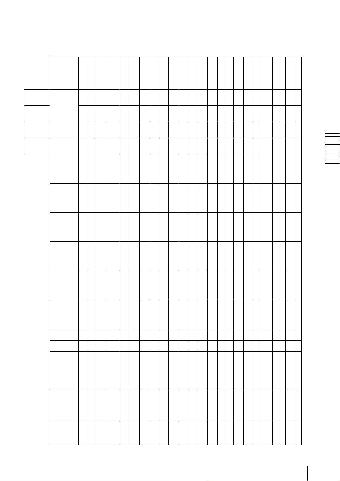
are cleared with the
reset butt on.
Initial iza-
tion by
pressing
the reset
button
for 3
seconds
--
When
rebooting
the
camera
or re-
turning
power on
are not retained in
the memory)
×: no change (items
are retained in the
memory)
-: no change (items
cannot be changed)
Items
that can
be loaded
from the
UserSet
(16
channels)
--
--
--
Items
that can
be saved
in the
UserSet
(16
channels)
aa× a Data that are stored
Command List
0x44FA0000
(2000) *1
0x3D800000
0x44FA0000
(2000) *1
0x44FA0000
(2000) *1
0x44FA0000
(2000) *1
0x44FA0000
(2000) *1
(0.0625) *1
0x3D800000
(0.0625) *1
0x3D800000
(0.0625) *1
0x3D800000
(0.0625) *1
0x3D800000
(0.0625) *1
1 (readout is
disabled)
1 (readout is
disabled)
1 (readout is
disabled)
1 (readout is
disabled)
1 (readout is
disabled)
1 (readout is
disabled)
1 (readout is
disabled)
1 (readout is
disabled)
1 (readout is
disabled)
1 (readout is
disabled)
0x0 to
0xFFFFFFFF
0x0 to
0xFFFFFFFF
0x0 to
0xFFFFFFFF
0x0 to
0xFFFFFFFF
0x0 to
0xFFFFFFFF
(2000) *1
(0.0625) *1
Write XCG-C30 XC G-C30C XCG-C32 XCG-C32C XCG-C130 XCG-C130C aaa: change (items
out
Address Model name Read-
a × 111111 -
a × 0x3FFF 0x3FFF 0x3FFF 0x3FFF 0x3FFF 0x3FFF -
Readout the minimum
Readout the AGC target
level maximum value
Max
0xA0002154 GainAutoSpeed AGC following speed aa 1 to (256) 1 to (256) 1 to (256) 1 to (256) 1 to (256) 1 to (256) aa aa
0xA00030FC GainAutoSpeed
0xA0007030 GainAutoLevel
value of AGC following
Min
speed
aa000000aaaa
a × 256 256 256 256 256 256 -
Setting o f AGC li mit
Readout the maximum
value of AGC following
speed
Max
0xA0002158 GainAutoLower
0xA0003100 GainAutoSpeed
a × 656 656 656 656 1296 1296 - -
aa502 502 502 502 502 502 aaaa
Setting o f AGC li mit
maximum value
minimum value
Limit
Limit
0xA0007000 WidthMax Acquisition of the image
0xA000215C GainAutoUpper
a × 492 492 492 492 964 964 - -
a × 16 16 16 16 16 16 - -
width minimum value
width maximum value
0xA0007008 HeightMax Acquisition of the image
0xA0007004 WidthMin Acquisition of the image
a × 0x44FA0000
a × 32 32 32 32 32 32 - -
Readout the frame rate
height minimum value
height ma ximum value
0xA0007010 AcquisitionFrameRat
0xA000700C HeightMin Acquisition of the image
× 658 658 658 658 1296 1296 - -
a × 0x3D800000
a
a × 494 494 494 494 966 966 - -
maximum value
Readout the frame rate
minimum value
width
eMax
eMin
0xA0007014 AcquisitionFrameRat
0xA00070D0 SensorWidth Acquisition of the sensor
0xA00070D8 SensorHeight Acquisition of the sensor
disabled)
disabled)
height
0xA0001000 UserSetSelector User set selector aa(0) to 16 (0) to 16 (0) to 16 (0 ) to 16 (0) to 16 (0) to 16 × a
0xA0001004 UserSetSave User set save × a 1 (readout is
0xA0001008 UserSetLoad User set load × a 1 (readout is
User set default aa(0) to 16 (0) to 16 (0 ) to 16 (0) to 16 (0) to 16 (0) to 16 × a
0xA000100C UserSetDefault
0xFFFFFFFF
Binarization threshold aa0 to (2047) to 4095 0 to (2047) to 4095 0 to (2047) to 4095 0 to (2047) to 4095 0 to (2047) to 4095 0 to (2047) to 4095 aaaa
UserMemoryValue User memory value aa0x0 to
Selector
0xA0001010 UserMemoryIndex User memory index aa (0) to 15 (0) to 15 (0) to 15 (0) to 15 (0) to 15 (0) to 15
0xA00020C0to0xA00020FC
Threshold
0xA0002060 LUTEnable LUT enable aa(0) / 1 (0) / 1 (0) / 1 (0) / 1 (0) / 1 (0) / 1 aaaa
0xA0000350 LUTIndex LUT user set index aa0 to 4095 0 to 4095 0 to 4095 0 to 4095 0 to 4095 0 to 4095 aa
0xA000205C LUTFormat LUT format aa(0) / 1 / 2 / 3 / 4 (0) / 1 / 2 / 3 / 4 (0) / 1 / 2 / 3 / 4 (0) / 1 / 2 / 3 / 4 (0) / 1 / 2 / 3 / 4 (0) / 1 / 2 / 3 / 4 aaaa
0xA0002064 Binarization
Command List
41
Page 42
but the acceptable
set.
set.
set.
Initial iza-
tion by
pressing
the reset
button
for 3
seconds
When
rebooting
the
camera
or re-
turning
power on
are not retained in
the memory)
×: no change (items
are retained in the
memory)
-: no change (items
cannot be changed)
Items
that can
be loaded
from the
UserSet
(16
channels)
Items
that can
be saved
in the
UserSet
(16
channels)
value is "0" only.
Command List
42
Command List
Write XCG-C30 XC G-C30C XCG-C32 XCG-C32C XCG-C130 XCG-C130C aaa: change (items
out
writing without spaces
Linear interpolation index aa 1 to 5 1 to 5 1 to 5 1 to 5 1 to 5 1 to 5 aaNot saved in the user
LUTValueFlat LUT user set address for
Address Model name Read-
0xA0010000 LUTValue LUT user set data aa0 to 4095 0 to 4095 0 to 4095 0 to 4095 0 to 4095 0 to 4095 - -
0xA0020000to0xA0023FFC
0xA0000340 LinearInterpolation
aa0 to 4095 0 to 4095 0 to 4095 0 to 4095 0 to 4095 0 to 4095 aaNot saved in the user
Linear interpolation out
Linear interpolation value aa0 to 4095 0 to 4095 0 to 4095 0 to 4095 0 to 4095 0 to 4095 aaNot saved in the user
InValue
Index
0xA0000348 LinearInterpolation
0xA0000344 LinearInterpolation
× a 111111
the flas h
Linear interpolation build × a 111111 --
value
Build
OutValue
0xA0000354 LineSelector Line selector aa (0) / 1 / 2 (0) / 1 / 2 (0) / 1 / 2 ( 0) / 1 / 2 (0) / 1 / 2 (0) / 1 / 2 aa
0xA0001204 LineMode(Line1) Line mode (Line1) aa 000000 --Writing is allowed,
0xA0002074 LUTValueSave Store the user set LUT in
0xA000034C LinearInterpolation
Line inverter (Line3) aa0 / (1) 0 / (1) 0 / (1) 0 / (1) 0 / (1) 0 / (1) aaaa
Line inverter (Line2) aa0 / (1) 0 / (1) 0 / (1) 0 / (1) 0 / (1) 0 / (1) aaaa
(Line3)
(Line2)
0xA0001208 LineMode(Line2) Line mode (Line2) aa (0) / 1 (0) / 1 (0) / 1 (0) / 1 (0) / 1 (0) / 1 aaaa
0xA000121C LineInverter
0xA000120C LineMode(Line3) Line mode (Line3) aa(0) / 1 (0) / 1 (0) / 1 (0) / 1 (0) / 1 (0) / 1 aaaa
0xA0001218 LineInverter
0xA0001224 LineStatus(Line1) Line status (Line1) a × ------ --
0xA0001228 LineStatus(Line2) Line status (Line2) a × ------ --
0xA000122C LineStatus(Line3) Line status (Line3) a × ------ --
0xA0001238 LineSource(Line2) Line source (Line2) aa 0 to (2) to 10 0 to (2) to 10 0 to (2) to 10 0 to (2) to 10 0 to (2) to 10 0 to (2) to 10 aa aa
Strobe active time (Line2 ) aa1 to (256) to 4000 1 to (256) to 4000 1 to (256) to 4000 1 to (256) to 4000 1 to (256) to 4000 1 to (256) to 4000 aaaa
Strobe active time (Line3 ) aa1 to (256) to 4000 1 to (256) to 4000 1 to (256) to 4000 1 to (256) to 4000 1 to (256) to 4000 1 to (256) to 4000 aaaa
(Line2)
(Line3)
0xA000123C LineSource(Line3) Line source (Line3) aa0 to (2) to 10 0 to (2) to 10 0 to (2) to 10 0 to (2) to 10 0 to (2) to 10 0 to (2) to 10 aaaa
0xA0001244 -
0xA0001248 StrobeActiveTime
0xA000124C StrobeActiveTime
Strobe delay (Line3) aa0 to (100) to 4000 0 to (100) to 4000 0 to (100) to 4000 0 to (100) to 4000 0 to (100) to 4000 0 to ( 100) to 4000 aa aa
Strobe delay (Line2) aa0 to (100) to 4000 0 to (100) to 4000 0 to (100) to 4000 0 to (100) to 4000 0 to (100) to 4000 0 to ( 100) to 4000 aa aa
(Line3)
(Line2)
0xA000125C StrobeActiveDelay
0xA0001254 - aa
0xA0001258 StrobeActiveDelay
User output (0) aa(0) / 1 (0) / 1 (0) / 1 (0) / 1 (0) / 1 (0) / 1 aaaa
User output selector aa(0) - 2 (0) - 2 (0) - 2 (0) - 2 (0) - 2 (0) - 2 aa
(0)
Selector
0xA0001264 UserOutputValue
0xA0001260 UserOutput
Page 43
information
Initial iza-
tion by
pressing
the reset
button
for 3
seconds
When
rebooting
the
camera
or re-
turning
power on
are not retained in
the memory)
×: no change (items
are retained in the
memory)
-: no change (items
cannot be changed)
Items
that can
be loaded
from the
UserSet
(16
channels)
aaaa
aaaa
aaaa
aaaa
aaaa
Items
that can
be saved
in the
UserSet
(16
channels)
aaaa
aaaa
aaaa
aaaa
Command List
-8191 to (0) to
8191
-8191 to (0) to
8191
-8191 to (0) to
8191
-8191 to (0) to
8191
-8191 to (256) to
8191
-8191 to (0) to
-8191 to (0) to
8191
-8191 to (0) to
8191
-8191 to (0) to
8191
-8191 to (0) to
8191
-8191 to (256) to
8191
-8191 to (0) to
-8191 to (0) to
8191
-8191 to (0) to
8191
-8191 to (0) to
8191
-8191 to (0) to
8191
-8191 to (256) to
8191
-8191 to (0) to
-8191 to (0) to
8191
-8191 to (0) to
8191
-8191 to (0) to
8191
-8191 to (0) to
8191
-8191 to (256) to
8191
-8191 to (0) to
-8191 to (0) to
8191
-8191 to (0) to
8191
-8191 to (0) to
8191
-8191 to (0) to
8191
-8191 to (256) to
8191
-8191 to (0) to
8191
8191
8191
8191
8191
-8191 to (0) to
8191
-8191 to (0) to
-8191 to (0) to
8191
-8191 to (0) to
8191
-8191 to (0) to
8191
-8191 to (0) to
8191
-8191 to (0) to
8191
8191
-8191 to (0) to
8191
-8191 to (0) to
8191
-8191 to (0) to
8191
-8191 to (0) to
8191
-8191 to (0) to
8191
-8191 to (0) to
8191
-8191 to (0) to
8191
-8191 to (0) to
8191
8191
8191
8191
8191
8191
8191
8191
Write XCG-C30 XC G-C30C XCG-C32 XCG-C32C XCG-C130 XCG-C130C aaa: change (items
out
User output (2) aa(0) / 1 (0) / 1 (0) / 1 (0) / 1 (0) / 1 (0) / 1 aaaa
User output (1) aa(0) / 1 (0) / 1 (0) / 1 (0) / 1 (0) / 1 (0) / 1 aaaa
(2)
(1)
Address Model name Read-
0xA0001268 UserOutputValue
0xA0000010 CameraReboot Device reset × a ------ --
0xA000126C UserOutputValue
0x0D04 GevSCPS Packet size aa(576) to 8228 (576) to 8228 (576) to 8228 (576) to 8228 (576) to 8228 (576) to 8228 aa
0x0D08 GevSCPD Packet delay aa000000 aa
0xA0000130 TestImageSelector Test image selector aa000000 aa
0xA100 ChunkModeActive Chunk mode is activated. aa (0) / 1 (0) / 1 (0) / 1 (0) / 1 (0) / 1 (0) / 1
0xA200 Chunk0Enable Chunk data 0 is enabled. aa(0) / 1 (0) / 1 (0) / 1 ( 0) / 1 (0) / 1 (0) / 1 Temperature
0xA210 Chunk1Enable Chunk data 1 is enabled. aa(0) / 1 (0) / 1 (0) / 1 (0) / 1 (0) / 1 (0) / 1 Line status
0xA220 Chunk2Enable Chunk data 2 is enabled. aa(0) / 1 (0) / 1 (0) / 1 ( 0) / 1 (0) / 1 (0) / 1 Exposure time
0xA230 Chunk3Enable Chunk data 3 is enabled. aa(0) / 1 (0) / 1 (0) / 1 ( 0) / 1 (0) / 1 (0) / 1 Analog gain
0xA240 Chunk4Enable Chunk data 4 is enabled. aa(0) / 1 (0) / 1 (0) / 1 (0) / 1 (0) / 1 (0) / 1 Pixel gain
aa(0) / 1 / 2 (0) / 1 / 2 (0) / 1 / 2 (0) / 1 / 2 (0) / 1 / 2 (0) / 1 / 2 aa
aa(0) / 1 (0) / 1 (0) / 1 (0) / 1 (0) / 1 (0) / 1 aaaa
Specify parameter
position (Row)
3 × 3 spatial filter is
enabled
SelectorRow
Enable
0xA0001804 SpatialFilter
0xA250 Chunk5Enable Chunk data 5 is enabled. aa(0) / 1 (0) / 1 (0) / 1 (0) / 1 (0) / 1 (0) / 1 User memory
0xA0001800 SpatialFilter
aa-8191 to (0) to
aa(0) / 1 / 2 (0) / 1 / 2 (0) / 1 / 2 (0) / 1 / 2 (0) / 1 / 2 (0) / 1 / 2 aa
Specify parameter
position (Column)
SelectorColumn
0xA0001808 SpatialFilter
aa-8191 to (0) to
For specifying individual
parameter
TopL eft
0xA000180C SpatialFilterValue Parameter value aa---- -- aa
0xA0001810 GigE_3x3Filter_
0xA0001814 GigE_3x3Filter_
aa-8191 to (0) to
aa-8191 to (0) to
aa-8191 to (256) to
aa-8191 to (0) to
aa-8191 to (0) to
TopC ent er
TopR ig ht
CenterLeft
CenterCenter
CenterRight
BottomLeft
0xA0001818 GigE_3x3Filter_
0xA0001820 GigE_3x3Filter_
0xA0001824 GigE_3x3Filter_
0xA0001828 GigE_3x3Filter_
0xA0001830 GigE_3x3Filter_
Command List
8191
8191
aa-8191 to (0) to
aa-8191 to (0) to
BottomRight
BottomCenter
0xA0001838 GigE_3x3Filter_
0xA0001834 GigE_3x3Filter_
0xA0001900 ColorMatrixEnable Color matrix is enabled. aa- (0) / 1 - (0) / 1 - (0) / 1 aaaa
43
Page 44
Initial iza-
tion by
pressing
the reset
button
for 3
seconds
When
rebooting
the
camera
or re-
turning
power on
are not retained in
the memory)
×: no change (items
are retained in the
memory)
-: no change (items
cannot be changed)
Items
that can
be loaded
from the
UserSet
(16
channels)
aaaa
aaaa
aaaa
aaaa
aaaa
aaaa
aaaa
aaaa
Items
that can
be saved
in the
UserSet
(16
channels)
aaaa
Command List
8191
8191
8191
8191
8191
8191
8191
8191
8191
- -8191 to (256) to
- -8191 to (0) to
- -8191 to (0) to
- -8191 to (0) to
- -8191 to (256) to
- -8191 to (0) to
- -8191 to (0) to
- -8191 to (0) to
- -8191 to (256) to
8191
8191
8191
8191
8191
8191
8191
8191
8191
- -8191 to (256) to
- -8191 to (0) to
- -8191 to (0) to
- -8191 to (0) to
- -8191 to (256) to
- -8191 to (0) to
- -8191 to (0) to
- -8191 to (0) to
- -8191 to (256) to
8191
8191
8191
8191
8191
8191
8191
8191
8191
- -8191 to (256) to
Write XCG-C30 XC G-C30C XCG-C32 XCG-C32C XCG-C130 XCG-C130C aaa: change (items
out
Address Model name Read-
aa- (0) / 1 / 2 - (0) / 1 / 2 - (0) / 1 / 2 aa
Specify parameter
position (Row)
SelectorRow
0xA0001904 ColorMatrix
aa- -8191 to (256) to
aa- (0) / 1 / 2 - (0) / 1 / 2 - (0) / 1 / 2 aa
Specify parameter
position (Column)
SelectorColumn
0xA0001908 ColorMatrix
aa- -8191 to (0) to
parameter
0xA000190C ColorMatrixValue Parameter value aa------ aa
0xA0001910 GigE_CM_TopLeft For specifying indivisual
0xA0001914 GigE_CM_Top
aa- -8191 to (0) to
aa- -8191 to (0) to
aa- -8191 to (256) to
aa- -8191 to (0) to
aa- -8191 to (0) to
aa- -8191 to (0) to
aa
Center
Right
Left
Center
Right
ft
nter
ght
0xA0001918 GigE_CM_Top
0xA0001920 GigE_CM_Center
0xA0001924 GigE_CM_Center
0xA0001928 GigE_CM_Center
0xA0001930 GigE_CM_BottomLe
0xA0001934 GigE_CM_BottomCe
0xA0001938 GigE_CM_BottomRi
44
Command List
Page 45
Specifications
Specifications
Pickup device Progressive scan CCD
XCG-C30/C30C/C130/C130C:
1/3 type
XCG-C32/C32C: 1/2 type
Standard video output size (horizontal/vertical)
XCG-C30/C30C/C32/C32C: 640×480
XCG-C130/C130C: 1,280×960
Frame rate XCG-C30/C30C: 130 fps
XCG-C32/C32C: 104 fps
XCG-C130/C130C: 31 fps
Lens mount C-mount
Flange focal length
17.526 mm
Video output signal
XCG-C30/C32/C130:
Mono 8 bits (default setting)/10 bits/
12 bits
XCG-C30C/C32C/C130C:
Raw 8 bits (default setting)/10 bits/
12 bits, RGB 24 bits, YUV 24 bits,
YUV 16 bits
Reference video output level
235 steps (8 bits)/3760 steps (12
bits)
Reference pedestal level
XCG-C30/C30C/C32/C32C/C130/
C130C:
16 steps (8 bits)/256 steps (12 bits)
Range of guarantee video output
XCG-C30/C30C/C32/C32C/C130/
C130C:
16 – 242 steps (8 bits)/256 – 3900
steps (12 bits)
Range of color temperature for white balance (color
camera only)
XCG-C30C/C32C/C130C:
2,400 K ~ 9,000 K
Minimum illumination
XCG-C30:
1.5 lx (gain control at +18 dB, F1.4,
shutter speed at 1/90 sec)
XCG-C32:
1.0 lx (gain control at +18 dB, F1.4,
shutter speed at 1/60 sec)
XCG-C130:
0.5 lx (gain control at +18 dB, F1.4)
XCG-C30C:
15 lx (gain control at +18 dB, F1.4,
shutter speed at 1/90 sec)
XCG-C32C/C130C:
12 lx (gain control at +18 dB, F1.4)
(only when shutter speed at 1/60 sec
for XCG-C32C)
Sensitivity XCG-C30/C32/C130:
F5.6 (gain control at 0 dB, 400 lx)
(only when shutter speed at 1/90 sec
for XCG-C30, 1/60 sec for XCGC32)
XCG-C30C/C32C/C130C:
F5.6 (gain control at 0 dB, 2,000 lx)
(only when shutter speed at 1/90 sec
for XCG-C30C, 1/60 sec for XCG-
C32C)
Gain 0 dB ~ 18 dB, Auto gain
Shutter speed 1/100,000sec to 2sec, automatic
shutter
Gamma γ=1 (Changeable by LUT)
Binning (during DC IN power supply only)
XCG-C30/C32/C130:
2×1, 1×2, 2×2
XCG-C30C/C32C/C130C:
Not included
External trigger pulse condition
pulse width: Between 10µs and 2s
amplitude: DC 2 V - 24 V (DC IN
connector)
External power DC 12 V (10.5 V - 15 V): DC IN
connector
IEEE802.3af (37 V to 57 V): RJ45
connector
Power consumption
XCG-C30/C30C/C32/C32C: 3.8 W
XCG-C130/C130C: 3.4 W
Performance guarantee temperature
0 °C to 40 °C (32 °F to 104 °F)
Operating temperature
–5 °C to +45 °C (23 °F to 113 °F)
Storage temperature
–30 °C to +60 °C (–22 °F to 140 °F)
Operating relative humidity
20% to 80% (no condensation)
Storage relative humidity
20% to 95% (no condensation)
MTBF About 6.1 years
Vibration resistance
10 G (20 Hz to 200 Hz)
Shock resistance70 G
External dimension (w/h/d)
29 × 29 × 42 mm (1
11
1
/16 inches) (excluding protrusions)
Mass About 66 g (1.9 oz)
Accessories Lens mount cap (1)
Operating Instructions (1)
Design and specifications are subject to change without
notice.
IMPORTANT
The nameplate is located on the bottom.
3
/16 × 1 3/16 ×
Specifications
Specifications
45
Page 46
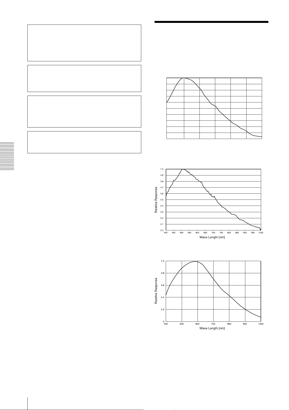
If the unit is suddenly taken from a cold to a warm location, or
if ambient temperature suddenly rises, moisture may form on
the outer surface of the unit and/or inside of the unit. This is
known as condensation. If condensation occurs, turn off the unit
and wait until the condensation clears before operating the unit.
Operating the unit while condensation is present may damage
the unit.
Spectral Sensitivity Characteristics (Typical Values)
Specifications
The life expectancy of the electrolytic capacitor is about 5 years
under normal operating temperatures and normal usage (8
hours per day; 25 days per month). If usage exceeds the above
normal usage frequency, the life expectancy may be reduced
correspondingly.
SONY WILL NOT BE LIABLE FOR DAMAGES OF ANY
KIND RESULTING FROM A FAILURE TO IMPLEMENT
PROPER SECURITY MEASURES ON TRANSMISSION
DEVICES, UNAVOIDABLE DATA LEAKS RESULTING
FROM TRANSMISSION SPECIFICATIONS, OR
SECURITY PROBLEMS OF ANY KIND.
Depending on the operating environment, unauthorized third
parties on the network may be able to access the unit. When
connecting the unit to the network, be sure to confirm that the
network is protected securely.
XCG-C30
1.0
0.9
0.8
0.7
0.6
0.5
0.4
Relative Response
0.3
0.2
0.1
0.0
400 500 600 700 800 900 1000
Wave Length [nm]
XCG-C32
XCG-C130
46
Spectral Sensitivity Characteristics (Typical Values)
Page 47
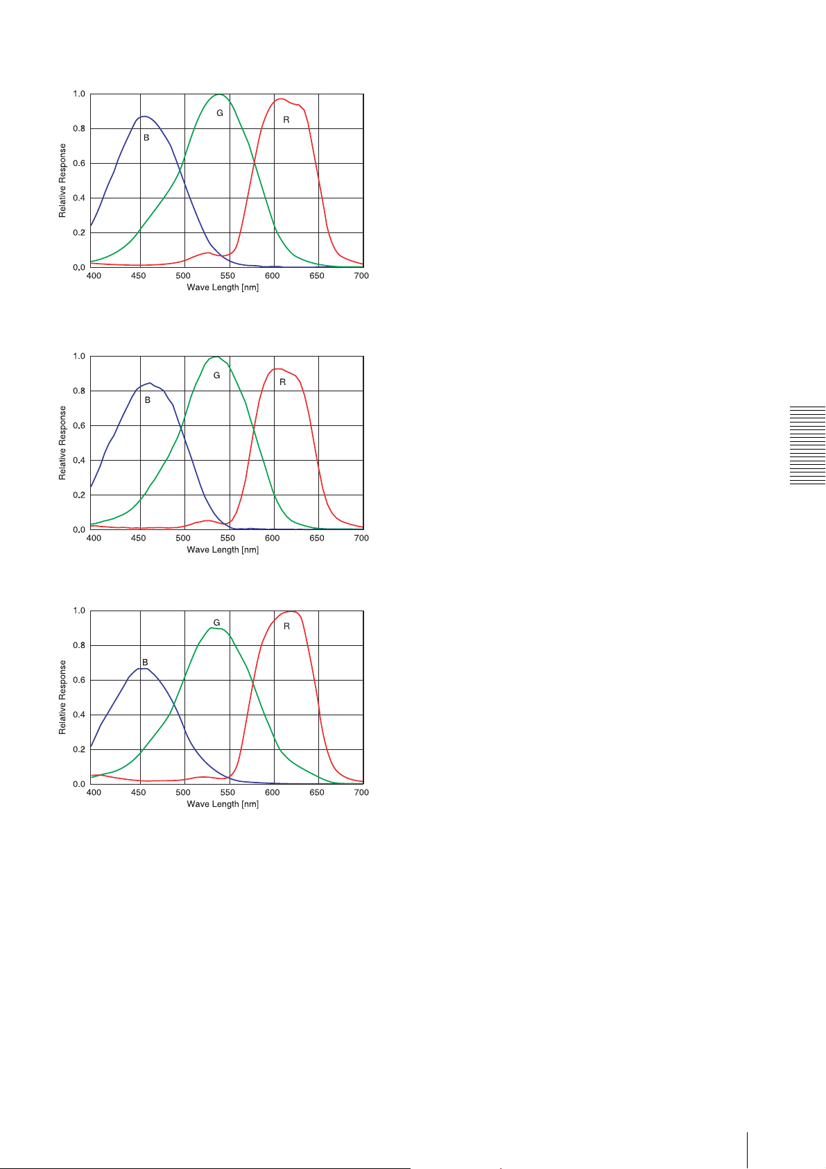
XCG-C30C
XCG-C32C
XCG-C130C
Specifications
Spectral Sensitivity Characteristics (Typical Values)
47
Page 48
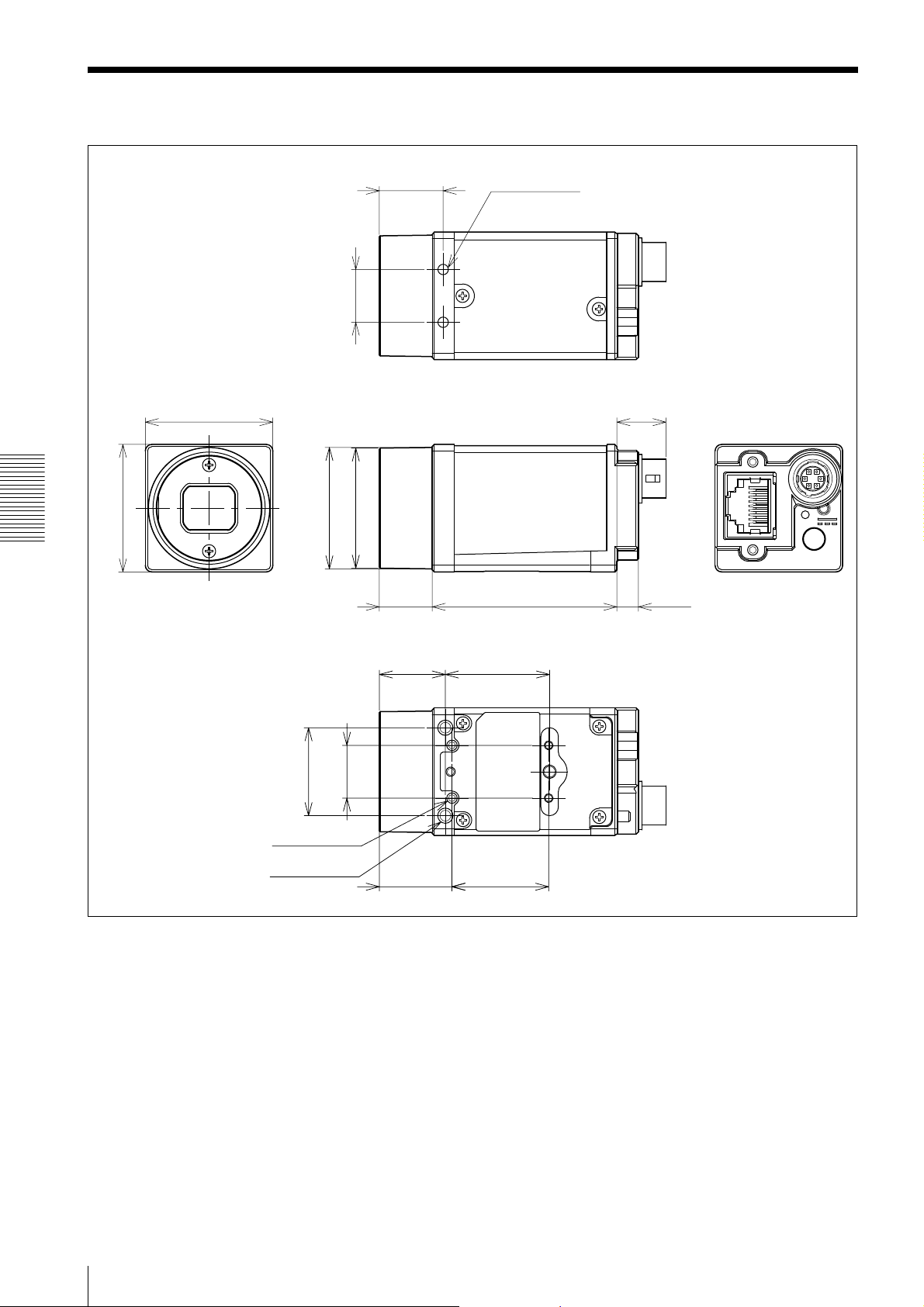
Dimensions
Specifications
)
16
/
3
29 (1
29 (1 3/16)
)
2
/
1
12 (
)
)
8
8
/
/
1
1
Ø27.6 (1
Ø27.3 (1
14.5 (19/32)
1
/2) 42 (1 11/16)
12 (
2 -M2 Depth 3
11.2 (
15
/32)
4.9 (
7
/32)
)
)
16
2
/
/
1
13
12 (
20 (
4 -M2 Depth 3
3 -M3 Depth 3
15 (19/32)
21
16.5 (
/32)
23.7 (
22 (
15
/16)
7
/8)
Unit: mm (inches)
48
Dimensions
Page 49

Sony reserves the right to change specifications of the products and discontinue products without notice.
Technical information contained herein is for reference only and does not convey any license by any implication or
otherwise under any intellectual property right or other right of Sony or third parties.
Sony cannot assume responsibility for any right infringements arising out of the use of this information.
Sony Corporation
 Loading...