

Page 1
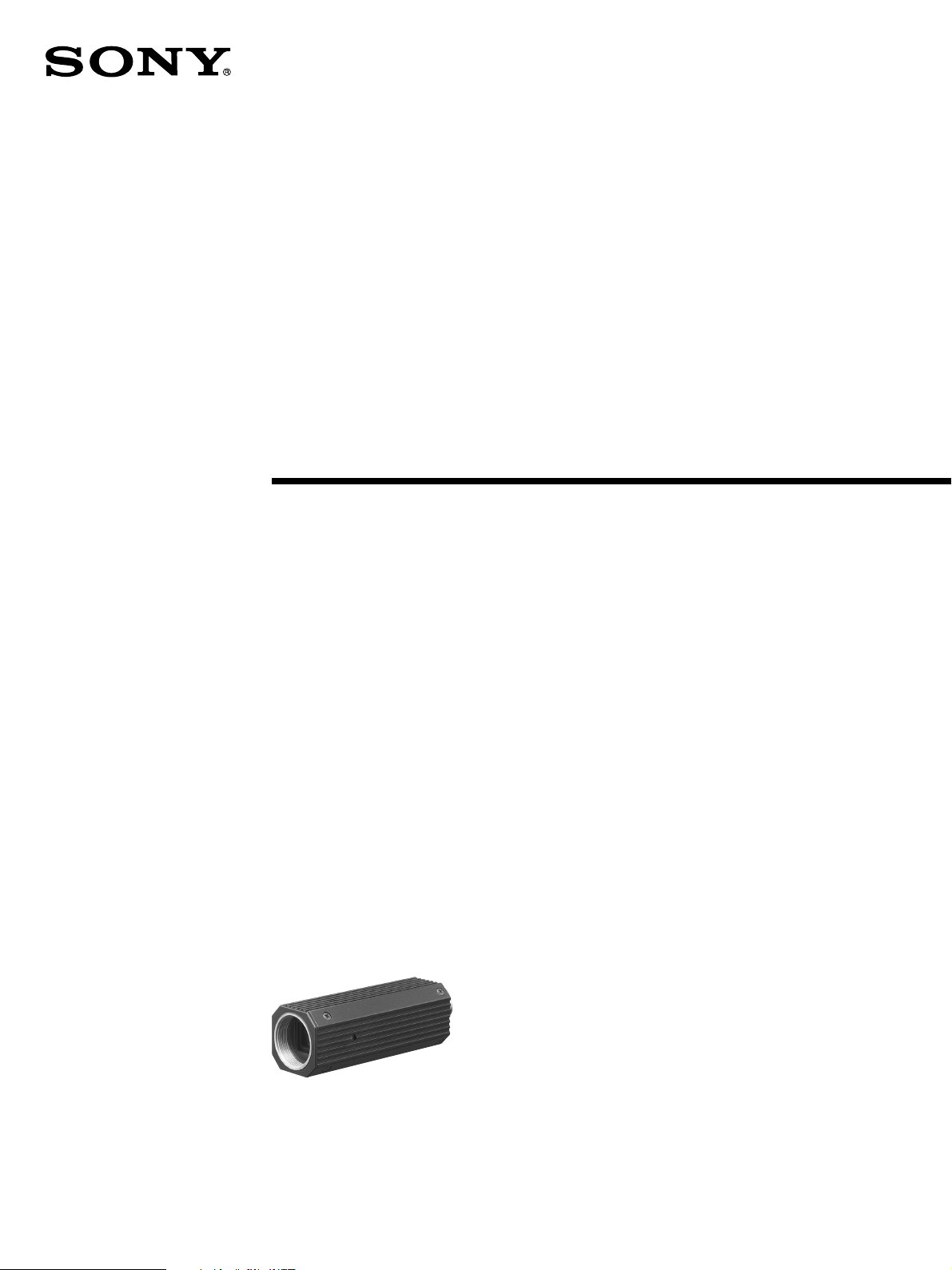
Color Video
Camera Module
A-DKO-100-11 (1)
Technical Manual
XC-505/505P
© 2010 Sony Corporation
Page 2

Table of Contents
Overview
Main Features...................................................................................3
Connection Diagram........................................................................4
Location of Parts and Operation ....................................................7
Mode Setting by Dip Switch............................................................8
Installation......................................................................................10
Connections ...................................................................................11
Genlock...........................................................................................12
RS-232C Command List
RS-232C Connector Pinouts.........................................................13
Communication Specifications ....................................................14
Camera Control Command List....................................................16
Camera Control Commands .........................................................18
Appendix
Camera Control Command List....................................................27
Specifications ................................................................................31
Dimensions ....................................................................................32
Spectral Sensitivity Characteristics (typical)..............................33
2
Table of Contents
Page 3

Overview
The XC-505/505P is a small color video camera module
that incorporates a 1/3-type IT CCD.
Main Features
Small Size and Lightweight
The camera is so small and light that you can install it
anywhere: even in locations where conventional video
cameras cannot be installed.
High Sensitivity
A built-in Super HAD II (Hole Accumulated Diode II)
sensor, allows high sensitivity, low smear images. You can
shoot, even under poor lighting conditions.
Simple Configuration via DIP Switch
available to allow you to match the shutter speed to the
shooting conditions.
When you set the DIP switches for the CCD IRIS function,
the shutter speed is adjusted automatically, based on the
amount of light allowed to enter, ensuring the most
appropriate level of image signal.
Advanced settings can be configured via RS-232C serial
communication. For details, see “Communication
Specifications” on page 14.
Function Setting via RS-232C
Transmissions
Using computer communications software such as
HyperTerminal and Tera Term, function switching can be
performed.
A variety of functions such as NR (2D/3D), edge
enhancement, γ, Nega/Posi, and Flip can be set via serial
communication. For details, see “Communication
Specifications” on page 14.
Gain, shutter speed, and white balance can be configured
using the 8-bit DIP switch located on the side of the unit.
Five White Balance Adjustment
Settings
Using the white balance DIP switches, you can choose
from among five white balance modes (3200K/5600K/
One Push WB/ATW/MAN) to choose the best settings for
shooting conditions, and the most appropriate color
compensation.
Electronic Shutter with a Wide
Range of Operating Speeds
Using the electronic shutter DIP switches, these levels of
shutter speed (OFF, 1/1,000, and FLICKERLESS) are
Main Features
3
Page 4
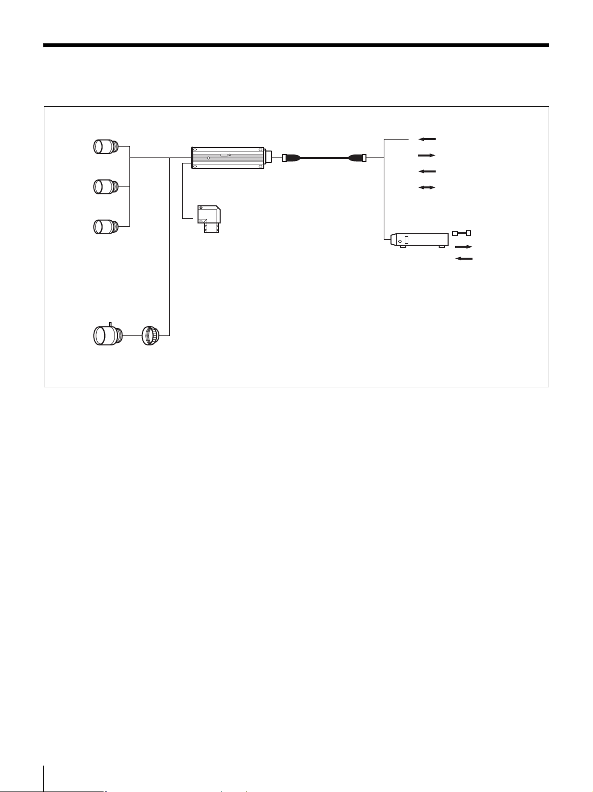
Connection Diagram
NF mount lens
VCL-03S12XM
VCL-06S12XM
VCL-12S12XM
C mount lens
(Manual iris)
XCK-L555
(Angle case kit)
LO-999CMT
(C-mount adaptor)
XC-505/505P
12P 12P
CCXC-12P02N
05N
10N
25N
DC-700
DC12V
VIDEO
HD/VD, VS, VBS
RS-232C
AC
VIDEO
HD/VD, VS, VBS
4
Connection Diagram
Page 5
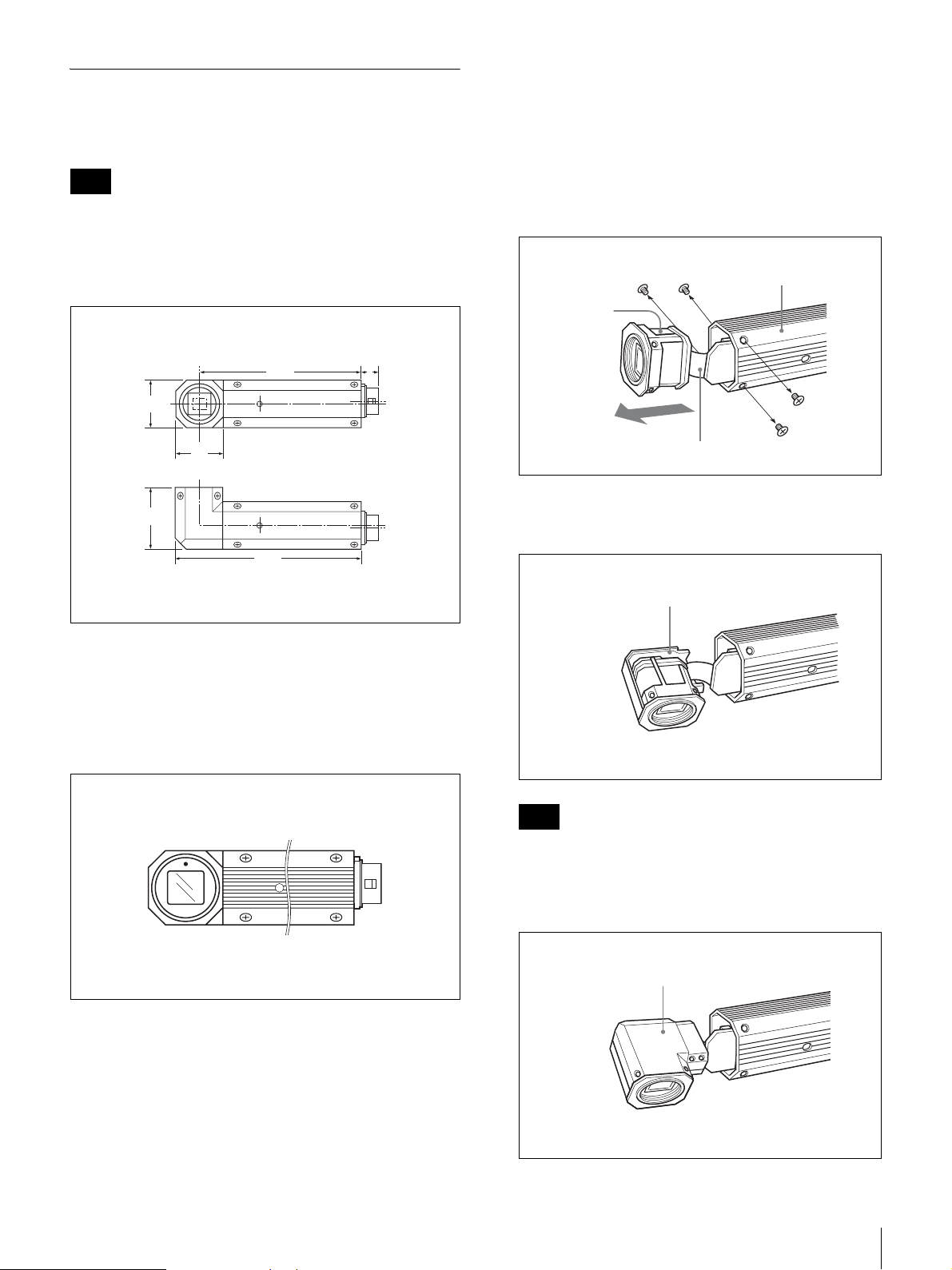
XCK-L555 Angle Case Kit
The XCK-L555 allows you to bend the XC-505/505P 90
degrees horizontally (HL).
Note
You can install XC-505/505P in only HL (horizontal)
directions. VL (vertical) is not available with this model.
Installation
Use angle case A/B and screws.
1
Remove the four screws (+PM1.7 × 3) from the front
panel.
The front block will pop out due to pressure from the
flexible cable.
Dimensions
505HL
74.3
22
22
28
85.3
8
UNIT: mm
Angle type
On the upper position of the Front block z is located. Set
the direction correctly while looking at the Front block
from the front so that z is in the upper position.
Dip switch: rear
Camera case
Front
block
Flexible cable
2
Attach the angle case (B) to the underside of the front
block.
Angle case (B)
Note
Do not pull the front block out forcibly. If you do so,
you may damage the flexible cable.
3
Attach the angle case (A) to the front block.
Angle case (A)
Connection Diagram
5
Page 6
4
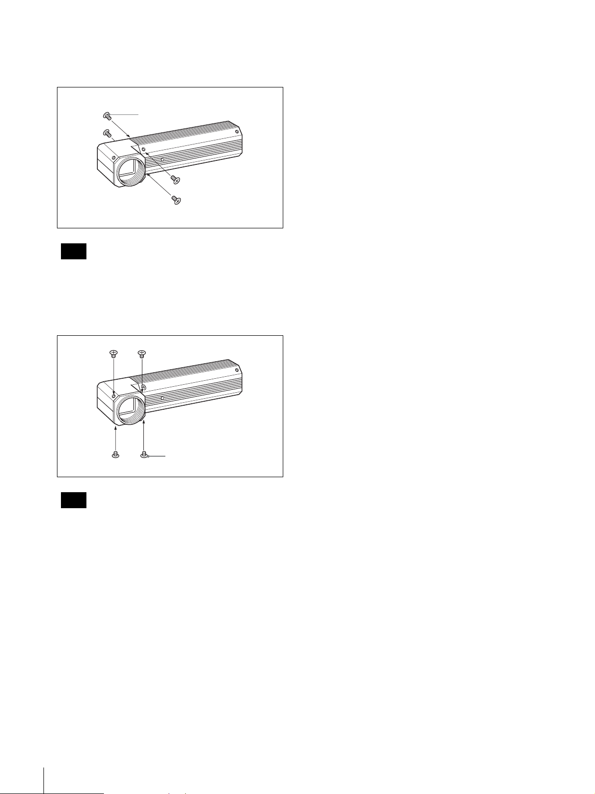
Insert the front block into the camera case, and attach
it securely using the four screws (+PM1.7 × 3)
removed in step 1.
Screw (+PM1.7 × 3)
Note
Tighten the screws to a torque level of 0.15 N•m for
the XC-505/505P.
5
Using the four screws (+K2 × 2.5) provided, attach
the angle case (A/B) and the front block securely.
Screw (+K2 × 2.5)
Note
Tighten the screws to a torque level of 0.18•Em.
6
Connection Diagram
Page 7
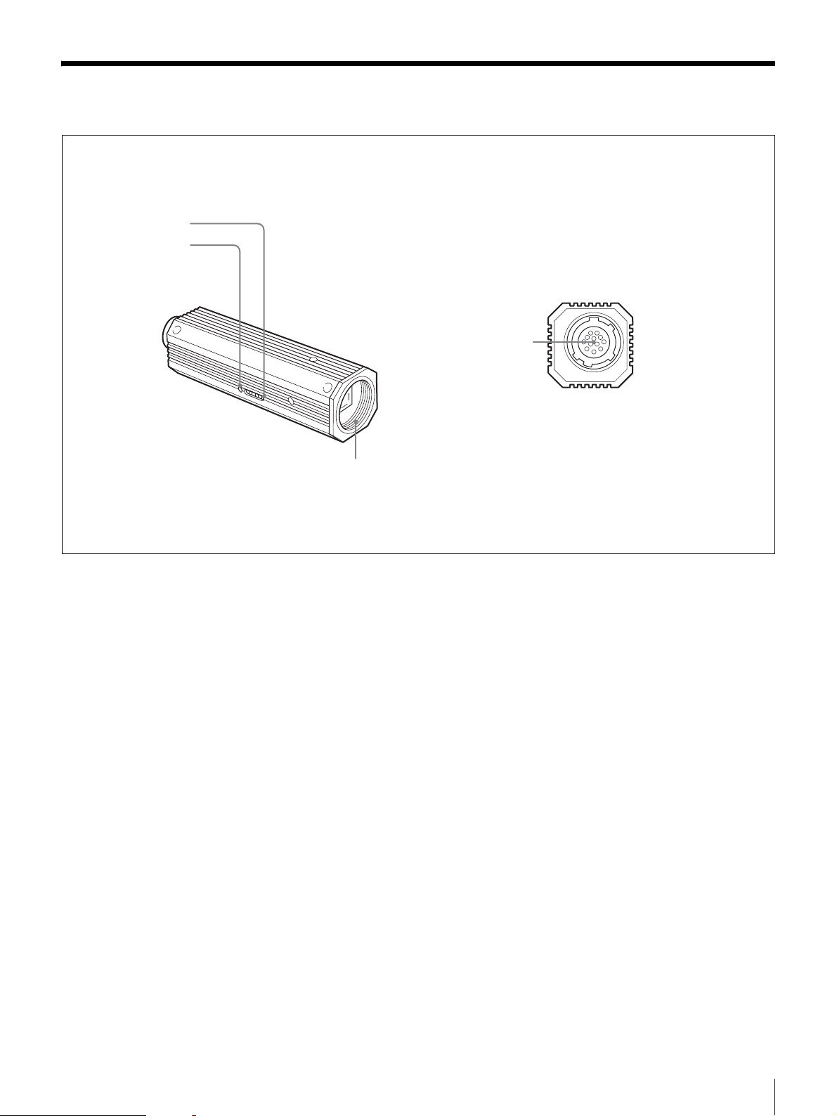
Location of Parts and Operation
1
2
3
4
a Dip switches for setting functions
This switches are used to adjust white balance and shutter
speed; and to flip AGC (ON/OFF) and output signals (Y/
C/VBS).
For details, see “Mode Setting by Dip Switch” on page 8.
b One Push WB switch
One Push white balance functions when the white balance
adjustment mode is set to One Push WB. The white
balance is automatically adjusted when this switch is
pressed, and the color balance is retained after adjustment.
c NF mount
d DC IN/SYNC/VIDEO connector (multi 12-pin)
This connector inputs DC 12 V power and outputs the
video signal when the CCXC-12P02N/12P05N/12P10N/
12P25N camera cable is connected.
If the unit is connected to devices that originate a
synchronized signal, the external synchronous signal (VS,
VBS, HD/VD) can be used to move the color camera
module.
VBS signals input as external synchronized signals
perform the same functions as VS signals. (Burst signals
are not locked and are free running.)
Location of Parts and Operation
7
Page 8
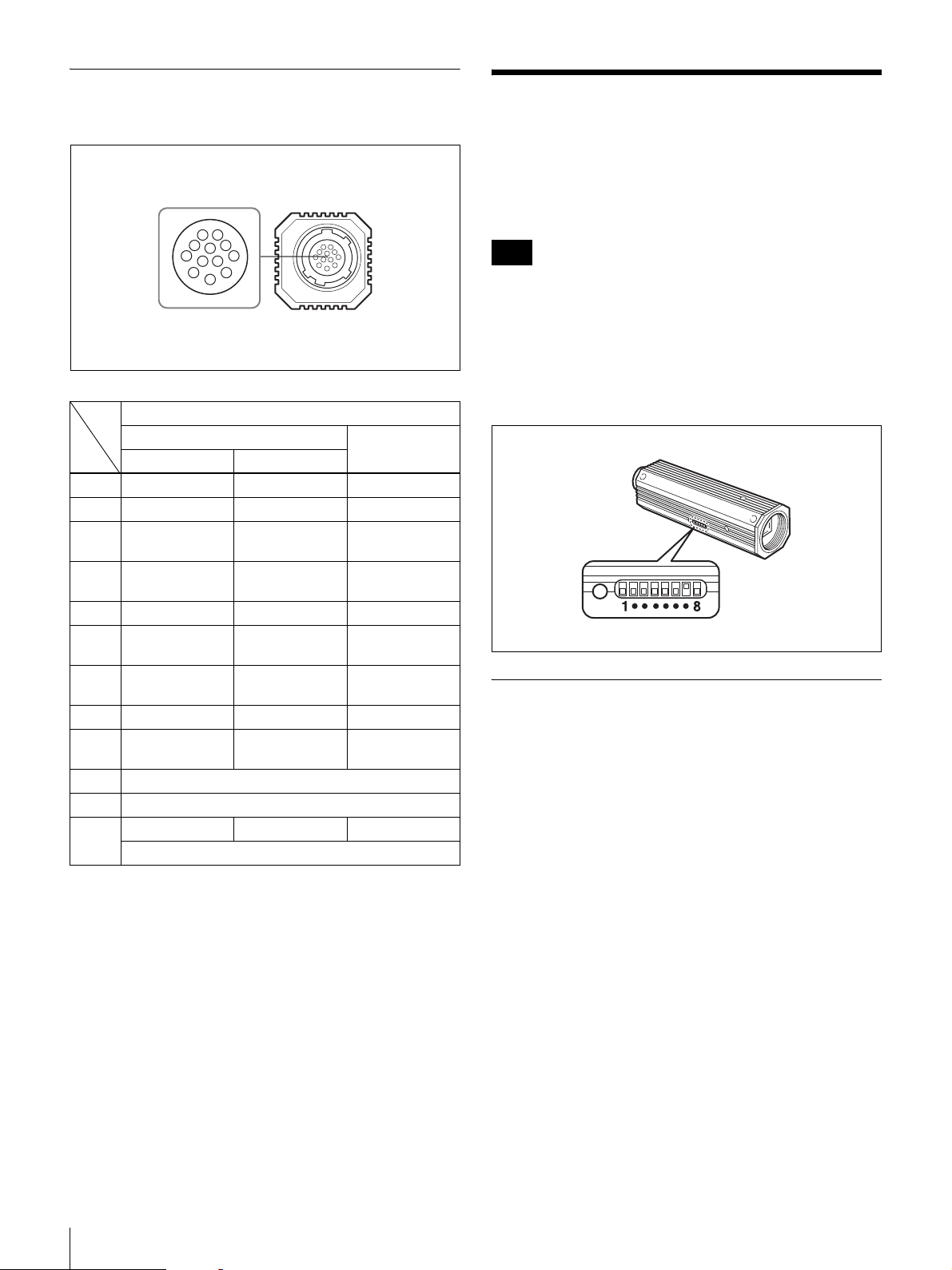
Pin Assignment of the DC IN/SYNC/
VIDEO Connector
9
1
2
8
10
3
7
12
11
6
4
5
Signal
External Sync signal
Rin No.
1 GND GND GND
2 +12 V +12 V +12 V
3 VBS/Y Output
4 VBS/Y Output
5 HD Input (GND) – –
6 HD Input
7 VD Input
8 GND (–/C) GND (–/C) GND (–/C)
9 –/C Output
10 RS-232C (TXD)
11 RS-232C (RXD)
12 VD Input (GND) VD Input (GND) GND
HD, VD VS/VBS Input
(GND)
(signal)
(signal)
(signal)
(signal)
Sync signal types
VBS/Y Output
(GND)
VBS/Y Output
(signal)
––
VS/VBS Input
(signal)
–/C Output
(signal)
RS-232C (GND)
Internal Sync
signal
VBS/Y Output
(GND)
VBS/Y Output
(signal)
–
–/C Output
(signal)
Mode Setting by Dip Switch
By flipping the DIP switches located on the side of this
camera, you can adjust the following functions.
Note
Each switch is assigned to a function. The switches that
should be set to adjust a certain function (white balance,
shutter speed), to switch the AGC (ON/OFF), or to switch
the output signals (Y/C/VBS) are specified and indicated
by shading in the illustrations of the corresponding
descriptions of the function. The switches that are not
shaded are not related to these functions.
Factory Settings
White balance: ATW
Shutter speed: OFF
AGC: ON
Output signal (Y/C/VBS): VBS
8
Mode Setting by Dip Switch
Page 9
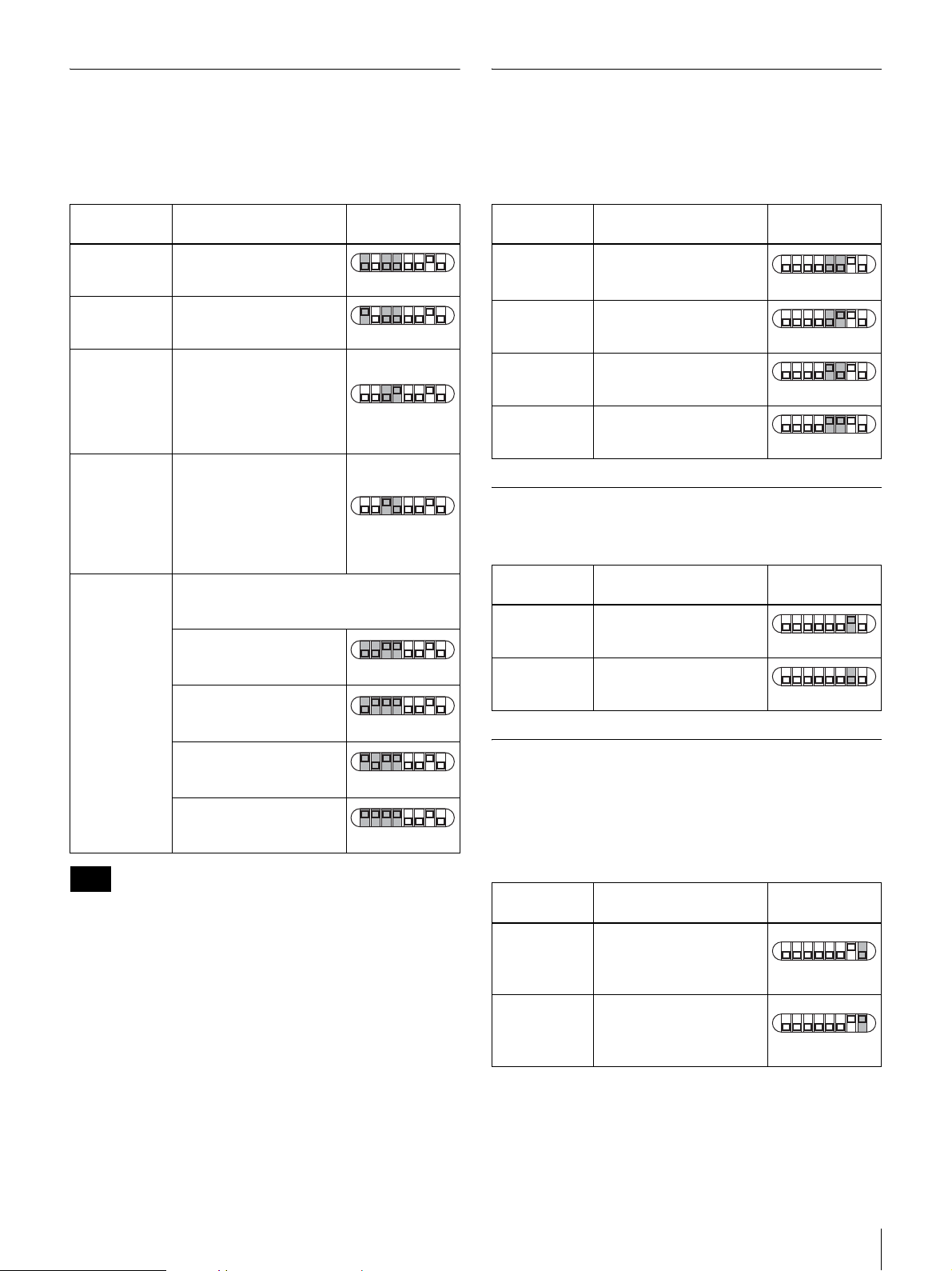
To Adjust the White Balance
To Adjust the Shutter Speed
Select the white balance setting according to the lighting
conditions.
To adjust the white balance, use bitXX (the shaded
switches).
DIP switch
setting
1······8
1······8
1······8
1······8
1······8
1······8
1······8
1······8
3200K
(fixed)
5600K
(fixed)
One Push WB
(One Push
white balance)
AT W
(auto tracing
white balance)
MAN
(manual)
Note
Lighting condition
For indoor shooting under
incandescent light.
For outdoor shooting on
sunny days.
The white balance is
automatically adjusted
when the One Push WB
switch is pressed, and the
color balance is retained
after adjustment.
The white balance is
adjusted according to the
color temperature
transition of the subject.
This mode is suitable for
shooting with variable
lighting (factory setting).
Manual white balance is adjusted using the
DIP switches in combination with the One
Push WB switch.
Red hues are subdued
with each press of the
One Push WB switch.
Red hues are enhanced
with each press of the
One Push WB switch.
Blue hues are subdued
with each press of the
One Push WB switch.
Blue hues are enhanced
with each press of the
One Push WB switch.
The correct white balance is obtained when a white subject
is shot on the whole detection area.
The correct color reproduction may not be obtained during
a normal scene shooting.
Set the shutter speed switches to select the desired shutter
speed. Using the CCD IRIS function, set the CCD IRIS
mode.
To adjust the shutter speed, use the shaded switches.
Shutter speed
OFF 1/60 sec. (XC-505)
1/50 sec. (XC-505P)
(factory setting)
1/1000 1/1,000 sec.
CCD IRIS Set the CCD IRIS mode.
FLICKERLESS
1/100 sec.
DIP switch
setting
1······8
1······8
1······8
1······8
AGC (Auto Gain Control) ON/OFF
To switch the AGC on or off, use the shaded switch.
Gain
ON Auto gain control
(factory setting)
OFF 0 dB
DIP switch
setting
1······8
1······8
To Switch the Output Signals (Y/C/
VBS)
Select the camera output signal.
To switch the output signals (Y/C/VBS), use the shaded
switch.
Output signal
VBS Select this position to
output the VBS signal
from the DC IN/VIDEO
(factory setting).
Y/C Select this position to
output the Y/C separated
signal from the DC IN/
VIDEO connector.
DIP switch
setting
1······8
1······8
Mode Setting by Dip Switch
9
Page 10
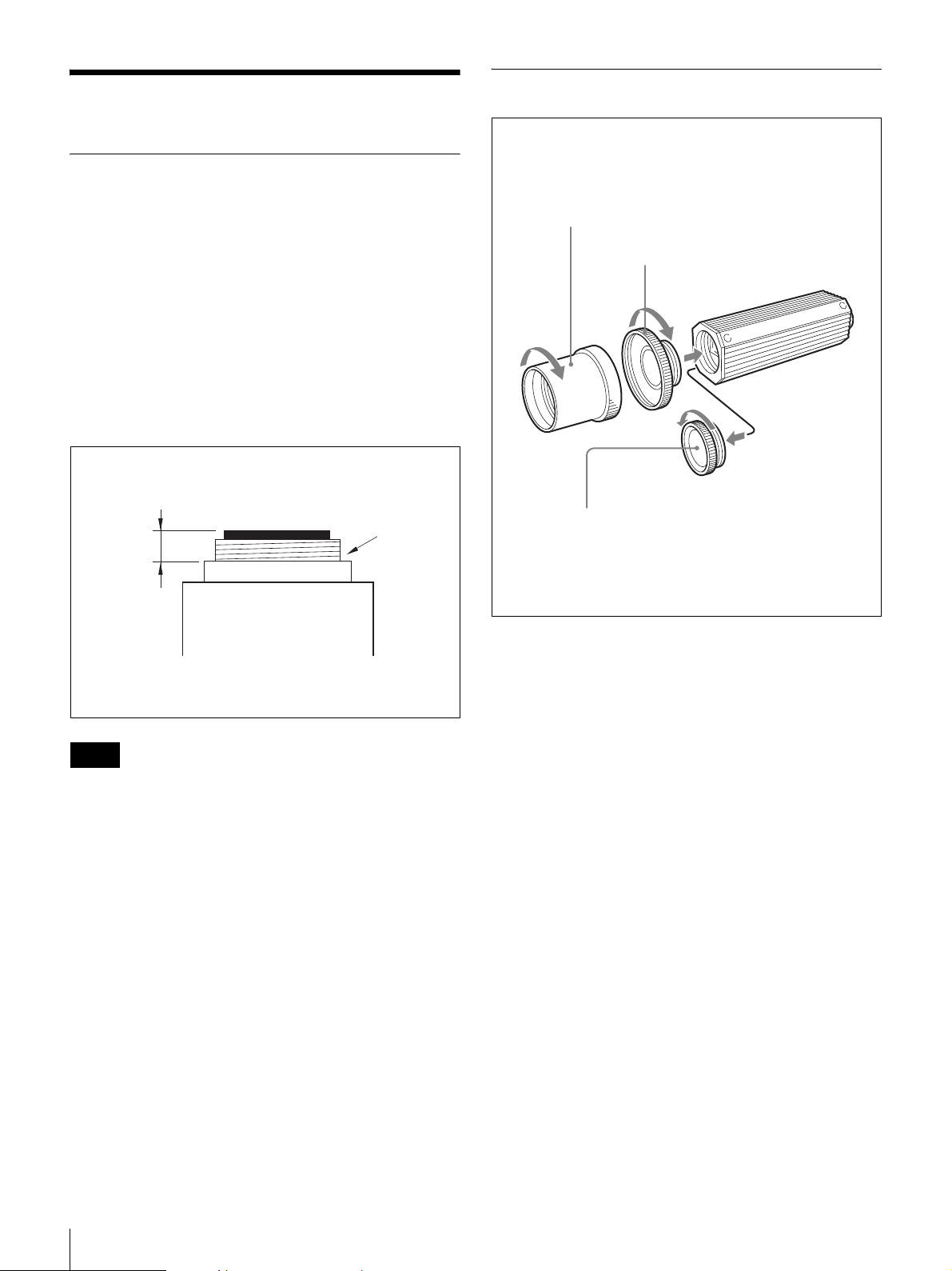
Installation
Usable Lenses
To Attach a Lens
•NF-mount lens
- VCL-06S12XM (f=6 mm)
- VCL-03S12XM (f=3.5 mm)
- VCL-12S12XM (f=12 mm)
The mounting thread of the NF-mount lens should not
extend more than 4.1 mm from the lens mount shoulder
(See below).
• C-mount lens
C-mount lens for 1/3-type sensor (The mounting thread
should not extend more than 4.1 mm from the lens mount
shoulder) (See below). When a C-mount type lens is
attached, a C-mount adaptor (LO-999CMT) is required.
Lens mount
shoulder
4.1 mm or
less
3
2
1
1
Remove the lens mount cap by turning it
counterclockwise.
Notes
• When connecting a heavy lens, make sure that it is
supported properly.
• When connecting heavy lens, make sure that it is not
subject to shocks or vibration.
2
Screw the C-mount adaptor (LO-999CMT) into the
lens mount of the camera. (only when using a C mount
lens)
3
Screw the lens.
10
Installation
Page 11
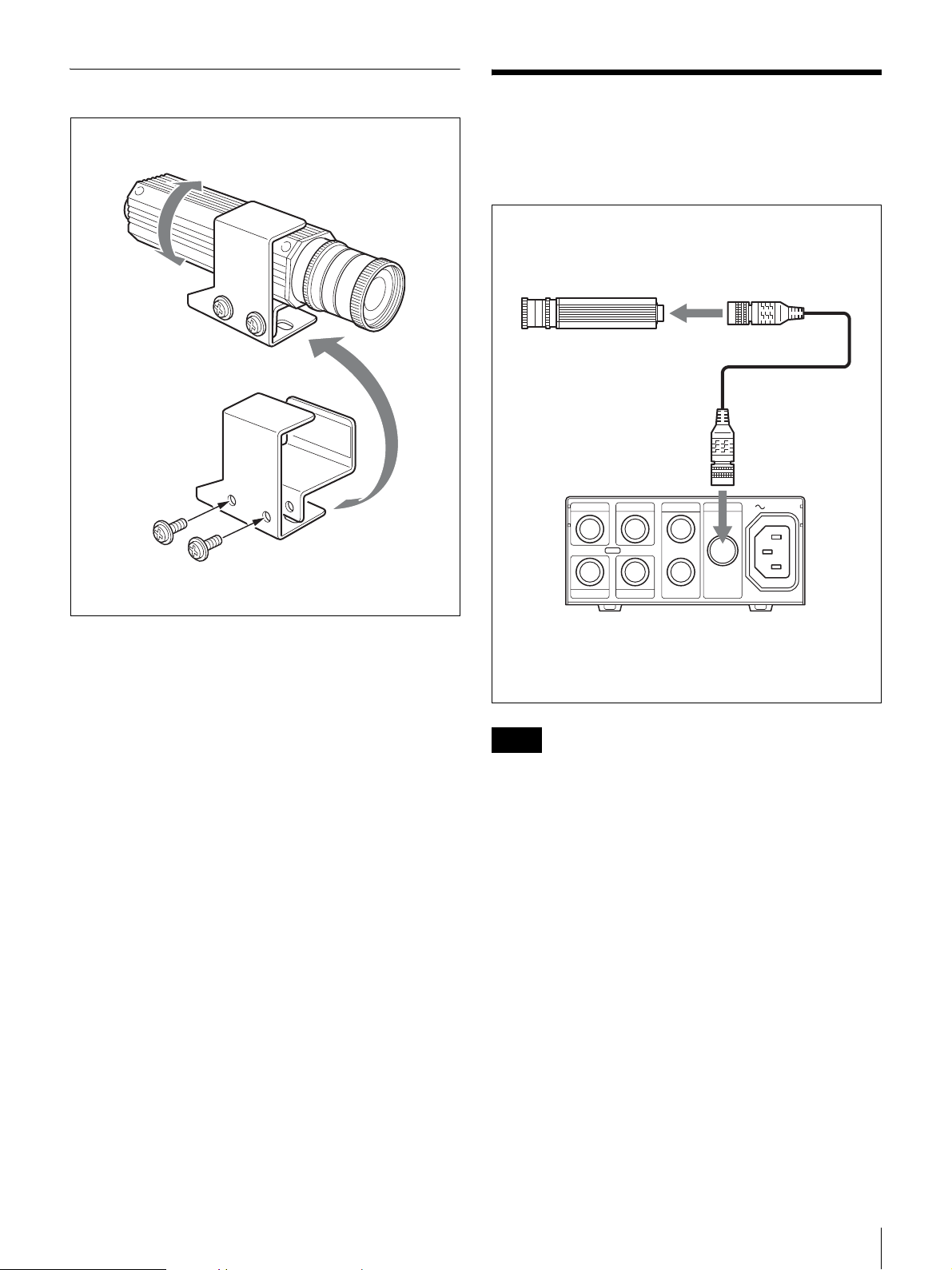
To Install the Camera on a Tripod
When you have finished installation, tighten the
screws to secure the module.
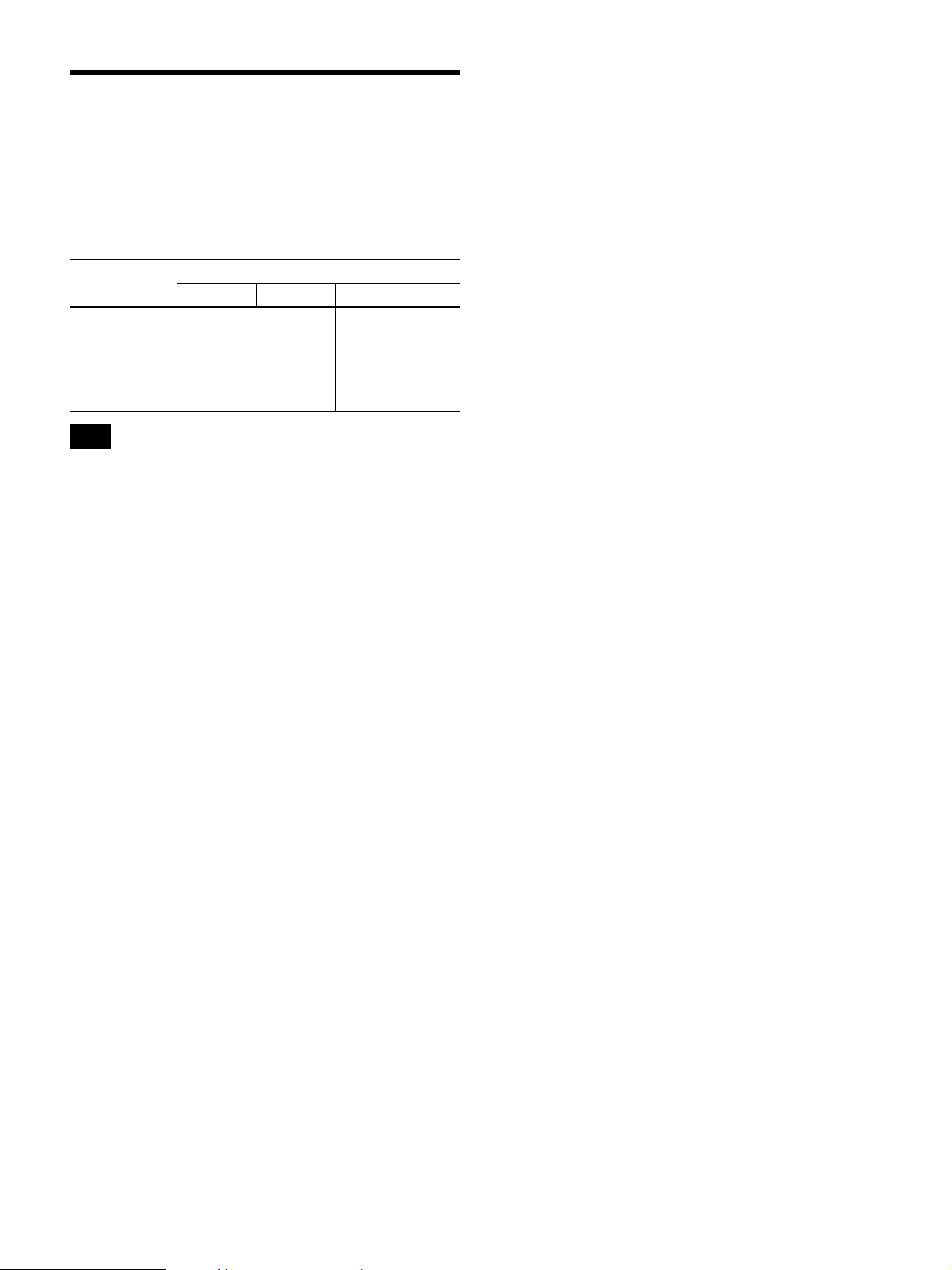
Connections
An example of the assembly of the DC-700/700CE
Camera Adaptor.
Color video camera module
to DC/IN/SYNC/VIDEO connector
CCXC-12P02N/12P05N/
12P10N/12P25N
DC-700/700CE
WEN
122
TRIGHDVD/SYNC
CAMERAVIDEO
1
AC IN
When mounting the camera on a tripod, use the supplied
tripod adaptor.
1
Assemble the tripod adaptor parts.
2
Mount the video camera module on the tripod adaptor.
Notes
• Make sure to turn off the power to the units you are
connecting or their components may be damaged.
• When disconnecting the cord, pull it out by the plug.
Never pull the cord itself.
• Connect the power cord after completing all other
connections.
Connections
11
Page 12
Genlock
The color video camera module is designed so that internal
sync and external sync are switched automatically. When
the color video camera module receives the following
external sync signal, the camera is synchronized to that
external sync signal.
Connection
example
Connection of
the camera
and the
DC-700/
DC-700CE
Note
HD/VD VS VBS
External sync signal
Genlock Genlock
(However, burst
signals not
locked. Same
function as VS
lock.)
Use a synchronous signal meeting the specifications given
in this Technical Manual. For details on the specifications,
see page 31.
12
Genlock
Page 13
RS-232C Command List
Hardware and software can be damaged by RS-232C
control programs developed using this command list. Sony
shall accept no liability for any such damage.
You can externally control various camera functions by
sending commands via the camera’s RS-232C interface.
Setting values for various functions can be stored in the
camera’s internal memory. The non-volatile internal
memory preserves data even without power, so you can
resume operation with the same settings when power is
restored.
RS-232C Command Usage
Precautions
Keep the following in mind regarding the RS-232C TXD
and RXD pins:
• Do not apply voltage exceeding ±10 V to RXD pin 11 of
the 12-pin connector.
• The output voltage on TXD pin 10 of the 12-pin
connector is typically within ±5.4 V. Do not apply
external voltage to this pin.
RS-232C Connector Pinouts
PC
D-SUB 9P
CD 1
RXD 2
TXD 3
DTR 4
GND 5
DSR 6
RTS 7
CTS 8
RI 9
XC-505/P
12 pin Connector
1 GND
2 +12 V
3 GND
4 VBS/Y out
5 GND
6 – /HD in
7 VS/VD in
8 GND
9 – /C out
10 TXD (RS-232C)
11 RXD (RS-232C)
12 GND
RXD
9
1
2
8
10
3
7
12
11
6
4
5
TXD
RS-232C Connector Pinouts
13
Page 14
Communication Specifications
Serial Communication
Specifications
The camera uses an RS-232C-conforming start-stop
synchronous serial interface.
Sent commands are remotely echoed back.
Baud rate: 38400/19200/9600 bps
Default: 38400 bps
Data length: 8 bits
Parity: none
Stop bit: 1 bit
Flow control: none
Command Format
Sent commands, consisting of a command name and
appended parameters, are input when followed by a
carriage return ASCII code.
Input syntax
command param1 param2 param3 [ENTER]
Input example
Item Character
Symbols ‘–’
‘+’
Space ‘ ’ 0x20 Not allowed at the
[BackSpace] BS
(control
character)
[ENTER] CR
(control
character)
Note
ASCII
Value
0x2D
0x2B
0x08 none
0x0D none
Numerical values
may be prepended
by a sign character.
‘+’ is allowed, but is
ignored.
beginning of a line.
Remarks
Commands may contain up to 64 characters (excluding the
ending CR).
Parameter Entry
Only base-10 (numerical) parameter values are accepted.
Valid values depend on the particular input command.
Commands with non-decimal parameter characters cannot
be processed.
Example. AE-REF (when received with a base-10
parameter)
<<Accepted normally >>
AE-REF 1023<CR>
GAIN-STEP 18<CR>
Command Input and Response
Status
Command Input
The camera accepts the following characters strings as
valid.
When the camera receives a valid character string, it is
remotely echoed back.
Item Character
Alphabetics ‘A’ to ‘Z’
‘a’ to ‘z’
Numerics ‘0’ to ‘9’ 0x30 to
ASCII
Val ue
0x41 to
0x5A
0x61 to
0x7A
0x39
Remarks
Strings are not
case-sensitive.
–
<<Returns the “ERROR PARAMETER” response
status>>
AE-REF 3FF<CR>
<<Returns the “ERROR PARAMETER” response
status>>
AE-REF ABC<CR>
AE-REF 1023ABC<CR>
Sign Operators
A “+” or “-” sign may be prepended to a parameter.
<<Accepted normally>>
GAIN-FINE +10<CR>
GAIN-FINE -10<CR>
<<Returns the “ERROR PARAMETER” response
status>>
GAIN-FINE +-10<CR>
GAIN-FINE 10-3<CR>
14
Communication Specifications
Page 15
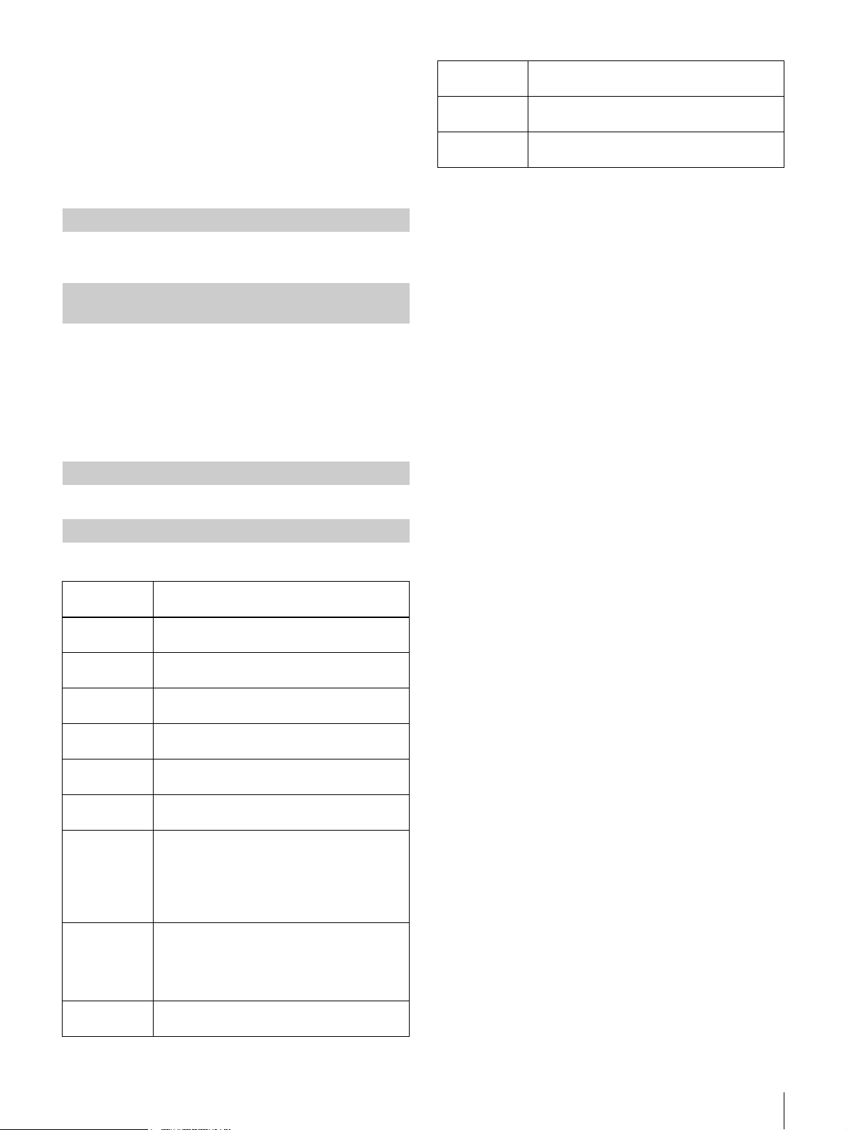
Omitted and Extra Parameters
Commands with omitted or extra parameters are ignored.
Also, entering a CR without any other input only changes
to the next line.
Example. SSHUTTER command with two
parameters
<<Accepted normally>>
SSHUTTER 0 1<CR>
<<Returns the “ERROR PARAMETER” response
status>>
SSHUTTER 0 1 1<CR>
SSHUTTER 0<CR>
Response Status
When an input command has finished processing, the
camera returns the response status to notify the user
whether it succeeded.
<<Input>>
AGAIN-STEP 12<CR>
Response
Status
AWB
TIMEOUT
AWB ERROR Appears when One-Push AWB execution
Appears when One-Push AWB execution
times out.
fails.
Description
<<Screen Output>>
ERROR SYNTAX<CR><LF>
Response Status from the Camera
Response
Status
OK OK appears at the end of the screen when
ERROR
SYNTAX
ERROR
STATUS
ERROR
PA RA ME T ER
ERROR
EEPROM
ERROR
EXECUTE
ERROR
BUSY
(Current
setting value)
AWB OK Appears when One-Push AWB execution
command execution finishes normally.
Appears when an invalid command name is
input.
Appears when command execution fails to
finish normally.
Appears when a command’s parameter
value is invalid.
Appears when an error occurs while
reading or writing a parameter in EEPROM.
Appears when an over-detection error
occurs during WPC-EXE execution.
Appears when a command is sent to the
camera before the response status for the
previous command has been returned.
This message is not displayed until at least
40 ms after the previous ERROR BUSY
was returned.
Sending a parameter setting command with
no parameter causes the current setting
value to be displayed.
Sending the HELP command with no
parameter displays the command list.
succeeds.
Description
Communication Specifications
15
Page 16
Camera Control Command List
Category Command
INIT Object
AE AE-MODE aa ××
AGCMAX-STEP aa ××
AGCMAX-FINE aa ××
CCDIRIS-MAX aa ××
SSHUTTER-MAX aa ××
AE-SPEED aa ××
AE-REF aa ××
GAIN-STEP aa ××
GAIN-FINE aa ××
SHUTTER aa××
SSHUTTER aa ××
WB WB-MODE aa ××
AUTOWB ××××
RGAIN aa ××
BGAIN aa ××
ATW-SPEED aa ××
CRS-MODE aa××
PICTURE DTL-MODE aa ××
DTL-ENHANCER aa ××
2DNR-MODE aa ××
3DNR-MODE aa ××
PEDESTAL aa ××
GAMMA-MODE aa ××
NEGAPOSI aa ××
WHITECLIP aa××
WPC WPC-MODE aa ××
WPC-EXE × × × ×
WPC-DISP a ×××
OPD OPD-DISP a ×××
OPD-AE-POS aa ××
OPD-AE-SIZE aa ××
OPD-AWB-POS aa ××
OPD-AWB-SIZE aa××
1)
Setting Value
SAVE Object
2)
Auto Saving
3)
Color Bar
Displaying
4)
16
Camera Control Command List
Page 17
Category Command
INIT Object
Setting Value
1)
SAVE Object
2)
Auto Saving
3)
Color Bar
Displaying
I / O VOUTSEL aa × a
HPHASE aa × a
VPHASE aa × a
COLORBAR a ××a
FLIP aa × a
BRATE × × aa
OSD aa × a
MEMO-CAPTURE × × × a
MEMO-DISPLAY a ××a
OtherINIT ×××a
SAVE × × × a
LOAD × × aa
RMEM ×××a
VERSION × × × a
HELP ×××a
1)
The INIT command initializes this command’s setting.
2)
The SAVE and LOAD commands apply to this command’s setting.
3)
When this command is sent, its setting is automatically saved to EEPROM.
4)
Commands are limited when the color bar is displayed: AE, WB, PICTURE, WPC, and OPD category commands return status errors.
4)
Camera Control Command List
17
Page 18
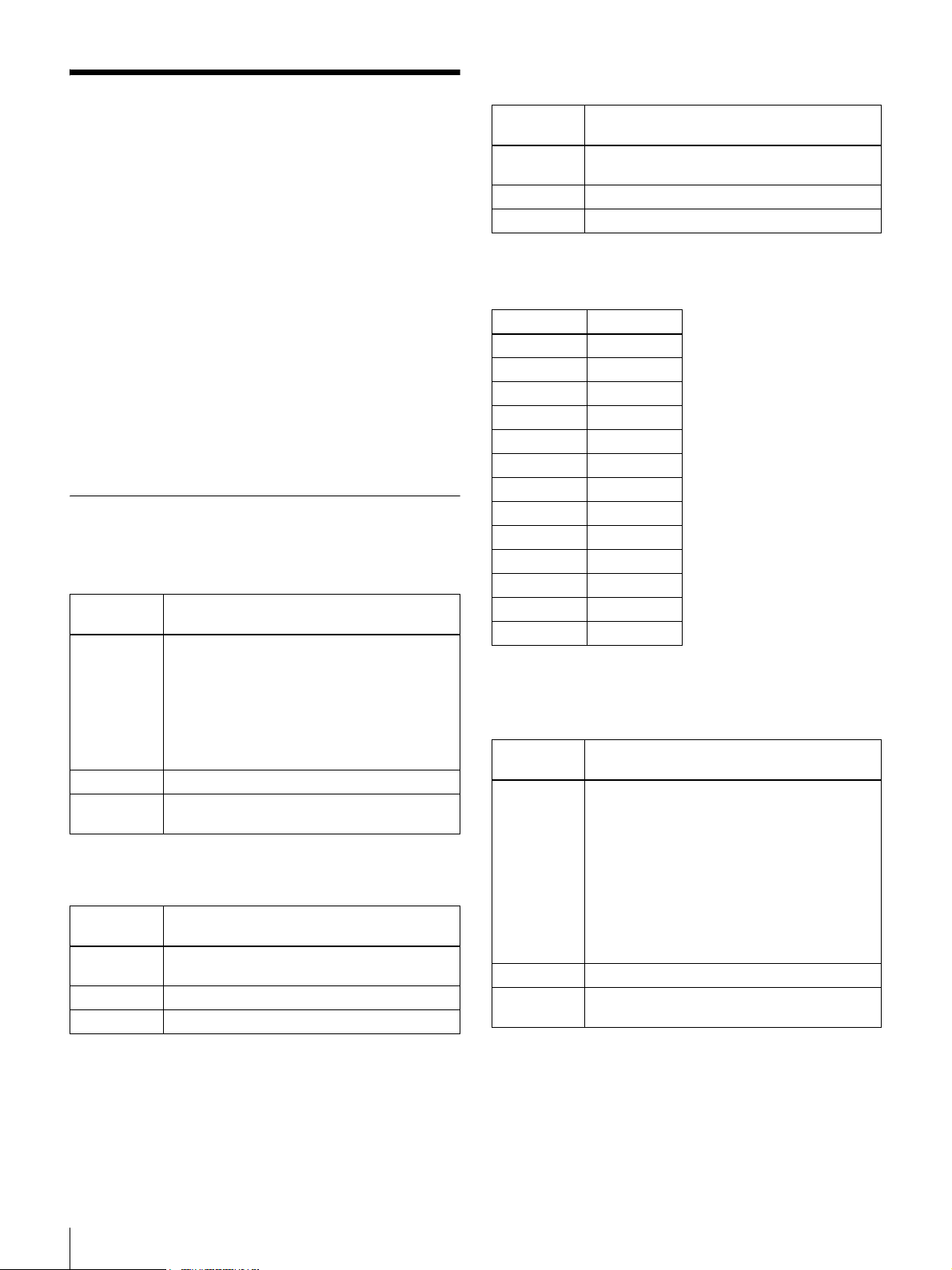
Camera Control Commands
Camera control commands are categorized as follows:
AE (Auto Exposure): Auto-exposure setting (page 18)
WB (White Balance): White balance setting (page 20)
PIC (Picture): Sharpness (aperture
compensation), noise reduction,
and video process settings
(page 21)
WPC (White Pixel Compensation):
White point detection and
compensation settings (page 22)
OPD (Optical Detector):
AE and AWB detection frame
settings (page 23)
IN/OUT: Input/output settings (page 23)
MEMO: Memo function settings (page 24)
AE (Auto Exposure)
AE Operation Mode Setting
Command
Name
Parameter 1 Operation Mode, 0 to 5
Conditions None
Process 0 and 1 select the ME operation mode, and
AGC Maximum Gain Setting (STEP)
Command
Name
Parameter 1 Gain: 6 to 18 [dB]
Conditions Valid when AE-MODE parameter 2 and 5.
Process Sets the upper gain limit for AGC.
AE-MODE
0: Fixed electronic shutter + fixed gain
1: Fixed electronic slow shutter + fixed gain
2: Fixed electronic shutter + AGC
3: CCD IRIS
4: CCD IRIS + Auto slow shutter
5: CCD IRIS + AGC
Default is Mode 2
other values set the AE mode.
AGCMAX-STEP
Default is 18 [dB]
AGC Maximum Gain Setting (FINE)
Command
Name
Parameter 1 Gain: 22 to 67
Conditions Valid when AE-MODE parameter 2 and 5.
Process Sets the upper gain limit for AGC.
The relationship between gain and fine settings are as
follows:
FINE Setting Gain (dB)
22 6
26 7
30 8
33 9
37 10
41 11
44 12
48 13
52 14
56 15
59 16
63 17
67 18
AGCMAX-FINE
Default is 67
CCD Iris Electronic Shutter Maximum
Speed Setting
Command
Name
Parameter 1 Max. electronic shutter speed: 0 to 8
Conditions Valid when AE-MODE is 3 to 5.
Process Sets the maximum speed of auto electronic
CCDIRIS-MAX
0: 1/100 [s]
1: 1/120 [s]
2: 1/250 [s]
3: 1/500 [s]
4: 1/1000 [s]
5: 1/4000 [s]
6: 1/10000 [s]
7: 1/50000 [s]
8: 1/100000 [s]
Default is 5
shutter control.
18
Camera Control Commands
Page 19
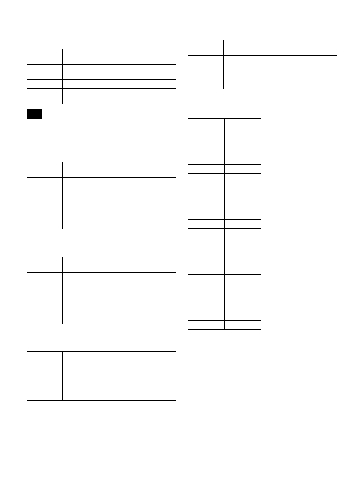
Slow Shutter Maximum Frame Count
Setting
Command
Name
Parameter 1 Max. frame count: 1 to 255
Conditions Valid when AE-MODE is 4.
Process Sets the maximum accumulatable frame
Note
The white point is higher with larger frame count settings,
but this is an artifact of the CCD and not a defect.
SSHUTTER-MAX
Default is 6 [frames]
count for auto slow shutter.
AE Convergence Speed Setting
Command
Name
Parameter 1 Convergence speed: 0 to 2
Conditions Valid when AE-MODE is 2 to 5.
Process Sets the AE convergence speed.
AE-SPEED
0: Slow
1: Normal
2: Fast
Default is 1
AE Reference Level Setting
Command
Name
Parameter 1 Reference Level: 0 to 1023
Conditions Valid when AE-MODE is 2 to 5.
Process Sets the AE reference level
AE-REF
0: Minimum to
100: Standard to
1023: Maximum
Default is 120
Fixed Step Gain Setting (FINE)
Command
Name
Parameter 1 Gain: –79 to +474
Conditions Valid when AE-MODE is 0 to 1.
Process Sets fixed AGC gain.
The relationship between gain and fine settings are as
follows:
FINE Setting Gain (dB)
–79 –3
–53 –2
–26 –1
00
26 1
53 2
79 3
105 4
132 5
158 6
184 7
211 8
237 9
263 10
289 11
316 12
342 13
368 14
395 15
421 16
447 17
474 18
GAIN-FINE
Default is 0
Fixed Step Gain Setting (STEP)
Command
Name
Parameter 1 Gain: –3 to +18 [dB]
Conditions Valid when AE-MODE is 0 to 1.
Process Sets fixed AGC gain.
GAIN-STEP
Default is 0 [dB]
Camera Control Commands
19
Page 20
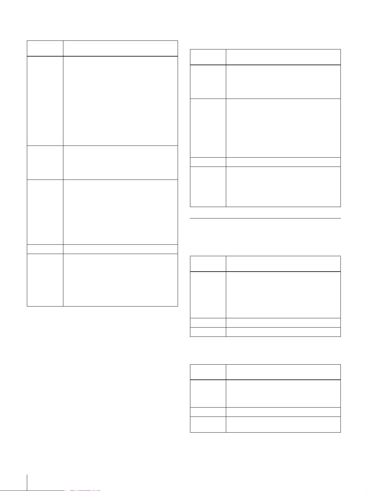
Fixed Electronic Shutter Speed Setting Fixed Electronic Slow Shutter Speed
Setting
Command
Name
Parameter 1 Electronic shutter speed: 0 to 12
Parameter 2 This is the electronic shutter speed
Parameter 3 This is the electronic shutter fine adjustment
Conditions Valid when AE-MODE is 0 and 2.
Process Sets the AE electronic shutter speed
SHUTTER
0: OFF (1/60 [s] for NTSC, 1/50 [s] for PAL)
1: 1/100 [s] (Flickerless NTSC operation)
2: 1/120 [s] (Flickerless PAL operation)
3: 1/250 [s]
4: 1/500 [s]
5: 1/1000 [s]
6: 1/2000 [s]
7: 1/4000 [s]
8: 1/10000 [s]
9: 1/50000 [s]
10: 1/100000 [s]
11: Arbitrary electronic shutter setting
Default is 0
adjustment value when parameter 1 is “11:
Arbitrary electronic shutter setting”
NTSC: 0 to 261
PAL: 0 to 311
value when parameter 1 is “11: Arbitrary
electronic shutter setting”
NTSC: 0 to 910
PAL: 0 to 908
However, when parameter 2 is 0 (NTSC or
PAL), the range for this parameter is as
follows:
NTSC: 143 to 910
PAL: 142 to 908
When parameter 1 is set to “11: Arbitrary
electronic shutter setting,” electronic shutter
timing is calculated as follows:
NTSC: (parameter 2) × 63.49 [µs] +
(parameter 3) × 69.84 [ns]
PAL: (parameter 2) × 64.00 [µs] +
(parameter 3) × 70.48 [ns]
Command
Name
Parameter 1 Fixed electronic slow shutter adjustment
Parameter 2 Fixed electronic slow shutter fine adjustment
Conditions Valid when AE-MODE is 1.
Process The fixed electronic slow shutter time is
SSHUTTER
value
NTSC: 0 to 255
PAL: 0 to 255
Default is 3
value
NTSC: 0 to 524
PAL: 0 to 624
However, when parameter 1 is 0 (NTSC or
PAL), the range for this parameter is as
follows:
NTSC: 262 to 524
PAL: 312 to 624
calculated as follows:
NTSC: (parameter 1) × 33.268 [ms] +
(parameter 2) × 63.49 [µs]
PAL: (parameter 1) × 39.936 [ms] +
(parameter 2) × 64.00 [µs]
WB (White Balance)
WB Mode Setting
Command
Name
Parameter 1 WB Mode: 0 to 4
Conditions None
Process Sets the WB mode.
WB-MODE
0: One Push AWB
1: ATW
2: Manual
3: Preset 3200K
4: Preset 5600K
Default is 1
20
Camera Control Commands
Manual R Gain Setting
Command
Name
Parameter 1 R gain: 0 to 4095
Conditions Valid when WB-MODE is 2.
Process Sets the R gain when WB Mode is
RGAIN
0: Minimum
4095: Maximum
Default R gain is 3200K
“2: Manual.”
Page 21
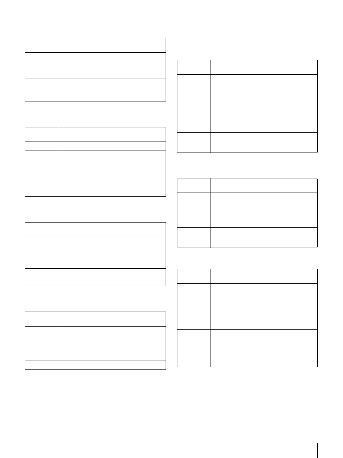
Manual B Gain Setting
PIC (Picture)
Command
Name
Parameter 1 B gain: 0 to 4095
Conditions Valid when WB-MODE is 2.
Process Sets the B gain when WB Mode is
BGAIN
0: Minimum to
4095: Maximum
Default B gain is 3200K
“2: Manual.”
One-Push AWB Execution
Command
Name
Parameter None
Conditions Valid when WB-MODE is 0.
Process Starts One-Push AWB processing.
AUTOWB
When processing is finished, one of the
following is returned:
AWB OK: Normal finish
AWB TIMEOUT: Time-out failure
AWB ERROR: Other failure
ATW Entrainment Speed Setting
Command
Name
Parameter 1 Entrainment speed: 0 to 2
Conditions Valid when WB-MODE is 1.
Process Sets the entrainment speed for ATW/CRS.
ATW-SPEED
0: Slow
1: Normal
2: Fast
Default is 1
CRS Setting during ATW
Command
Name
Parameter 1 CRS Mode, 0 to 1
Conditions Valid when WB-MODE is 1.
Process Enables or disables the CRS function.
CRS-MODE
0: OFF
1: ON
Default is 0
Aperture Compensation Mode Setting
Command
Name
Parameter 1 Aperture Compensation Mode: 0 to 4
Conditions None
Process Sets the aperture compensation mode.
DTL-MODE
0: Off
1: Vertical aperture compensation
2: Horizontal aperture compensation
3: Vertical + horizontal aperture
compensation
4: Highlight aperture compensation
Default is 2
Increases sharpness by emphasizing image
contours.
Detail Enhancer Setting
Command
Name
Parameter 1 Detail enhancer enable/disable setting: 0 to 1
Conditions None
Process Enhances signal details that may be
DTL-ENHANCER
0: OFF
1: ON
Default is 0
obscured by normal contour emphasis
(aperture compensation) processing.
2D-NR Setting
Command
Name
Parameter 1 Filter selection: 0 to 3
Conditions None
Process Sets the strength of 2D-NR noise
2DNR-MODE
0: 2D-NR disabled
1: Mild 2D-NR
2: Moderate 2D-NR
3: Strong 2D-NR
Default is 1
suppression. Higher noise suppression
corresponds to lower resolution.
The 2D-NR function performs spatial filtering
on an image to suppress noise effects within
a specific range.
Camera Control Commands
21
Page 22
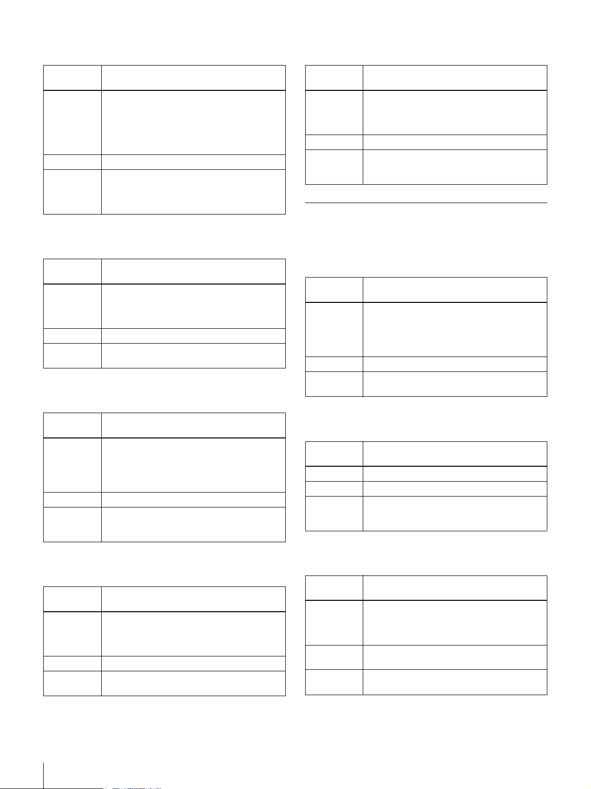
3D-NR Setting
High Brightness Clipping Setting
Command
Name
Parameter 1 Filter selection: 0 to 3
Conditions None
Process Sets the strength of 3D-NR noise
3DNR-MODE
0: 3D-NR disabled
1: Mild 3D-NR
2: Moderate 3D-NR
3: Strong 3D-NR
Default is 0
suppression. Higher noise suppression
corresponds to lower dynamic resolution as
the afterimage becomes more visible.
Pedestal Setting
Command
Name
Parameter 1 0 to 22 (corresponds to NTSC: 0 to 10 [IRE],
Conditions None
Process Adjusts the pedestal.
PEDESTAL
and PAL: PAL 0 to 70 [mV])
Default is 11 (NTSC: 5 [IRE], and PAL: 35
[mV])
Does not affect gamma-curve compensation.
Gamma Table Setting
Command
Name
Parameter 1 Brightness signal clipping level: 0 to 63
Conditions None
Process Clips brightness exceeding the specified level
WHITECLIP
0: Minimum to
1: Maximum (no clipping)
Default is 63
in the final output of the Y signal.
Use this function to avoid image whiteout.
WPC (White Pixel Compensation)
Enable/Disable White Point Detection
Compensation
Command
Name
Parameter 1 White point detection compensation enable/
Conditions None
Process Enables or disables auto detection of white
WPC-MODE
disable: 0 to 1
0: OFF
1: ON
Default is 1
point compensation.
Command
Name
Parameter 1 Gamma curve: 0 to 2
Conditions None
Process Specifies the gamma curve of the YC signal
GAMMA-MODE
0: γ = 1.0
1: γ = 0.45(γ = 1/2.2)
2: γ = 0.6(γ = 1/1.6)
Default is 1
(the specified C is used regardless of the
GAMMA-MODE setting.)
Polarity (Nega/Posi) Setting
Command
Name
Parameter 1 Polarity: 0 to 1
Conditions None
Process Inverts the YC signal after gamma curve
NEGAPOSI
0: Positive
1: Negative
Default is 0
compensation.
Execute Auto White Point Detection
Command
Name
Parameter None
Conditions None
Process Starts auto white point detection processing.
WPC-EXE
Execute with the lens covered, such as by a
lens cap.
White Point Compensation Marker Setting
Command
Name
Parameter 1 Marker display/non-display: 0 to 1
Conditions Display is only possible when WPC-MODE is
Process The marker indicates the white point location
WPC-DISP
0: OFF
1: ON
Default is 0
1.
on the object of compensation.
22
Camera Control Commands
Page 23
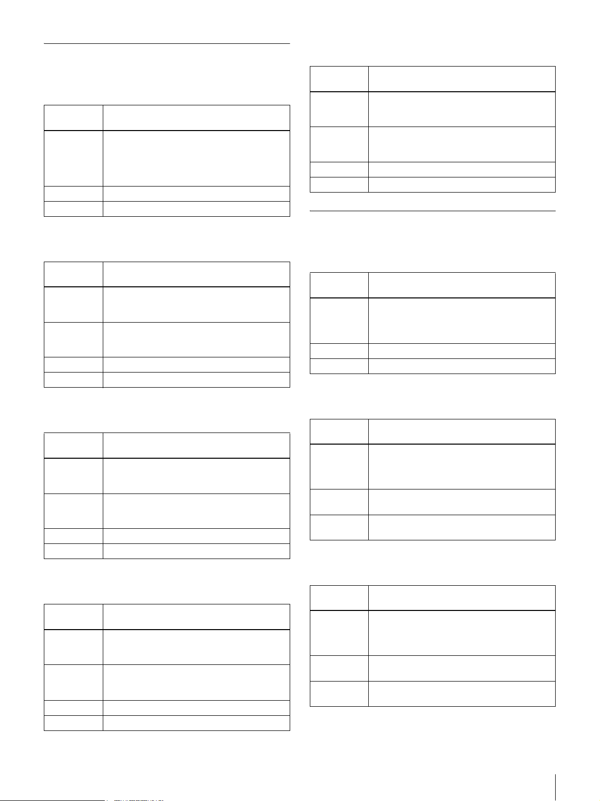
OPD (Optical Detector)
OPD-AWB Size Setting
OPD Frame Display Setting
Command
Name
Parameter 1 OPD frame display: 0 to 2
Conditions None
Process Displays the detection frame for AE or AWB.
OPD-DISP
0: OFF
1: AE
2: AWB
Default is 0
OPD-AE Position Setting
Command
Name
Parameter 1 X-coordinate of center of OPD frame [%]
Parameter 2 Y-coordinate of center of OPD frame [%]
Conditions None
Process Sets the position of the AE detection frame.
PD-AE-POS
Settable range is 25 to 75
Default is 50
Settable range is 25 to 75
Default is 50
Command
Name
Parameter 1 OPD frame width
Parameter 2 Y-coordinate of center of OPD frame [%]
Conditions None
Process Sets the size of the AWB detection frame.
OPD-AWB-SIZE
Settable range is 50 to 100
Default is 50
Settable range is 50 to 100
Default is 50
IN/OUT
VBS/YC Output Selection
Command
Name
Parameter 1 Output signal: 0 to 1
Conditions None
Process Selects VBS or YC output signal format.
VOUTSEL
0: VBS
1: Y/C
Default is 0
OPD-AE Size Setting
Command
Name
Parameter 1 OPD frame width
Parameter 2 Y-coordinate of center of OPD frame [%]
Conditions None
Process Sets the size of the AE detection frame.
OPD-AE-SIZE
Settable range is 50 to 100
Default is 50
Settable range is 50 to 100
Default is 50
OPD-AWB Position Setting
Command
Name
Parameter 1 X-coordinate of center of OPD frame [%]
Parameter 2 Y-coordinate of center of OPD frame [%]
Conditions None
Process Sets the position of the AWB detection frame.
OPD-AWB-POS
Settable range is 25 to 75
Default is 50
Settable range is 25 to 75
Default is 50
H-Phase Setting
Command
Name
Parameter 1 H-phase setting value:
Conditions Valid only when the camera is operated with
Process Sets the H-phase adjustment value when
HPHASE
0 to 910 (NTSC)
0 to 908 (PAL)
Default is 104
external synchronization.
using external synchronization.
V-Phase Setting
Command
Name
Parameter 1 V-phase setting value:
Conditions Valid only when the camera is operated with
Process Sets the V-phase adjustment value when
VPHASE
0 to 262 (NTSC)
0 to 312 (PAL)
Default is 10
external synchronization.
using external synchronization.
Camera Control Commands
23
Page 24
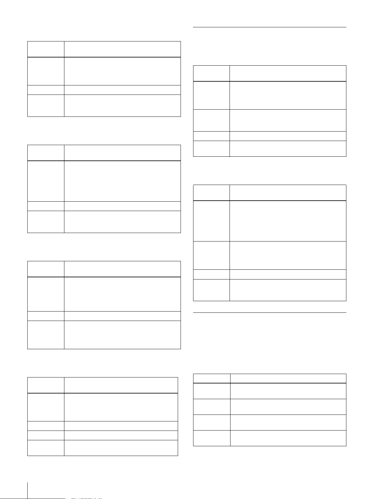
Internal Color Bar Output Setting
MEMO
Command
Name
Parameter 1 Color bar output setting ON/OFF: 0 to 1
Conditions None
Process Enables or disables color bar output.
COLORBAR
0: ON
1: OFF
Default is 0
When ON, the display shows 100% color
bars.
Flip Output Setting
Command
Name
Parameter 1 Flip setting: 0 to 3
Conditions None
Process Sets the flip output mode.
FLIP
0: OFF
1: Flip horizontally
2: Flip vertically
3: Flip horizontally and vertically
Default is 0
The output image can be flipped horizontally
and vertically.
Serial Communication Speed Setting
Command
Name
Parameter 1 Baud rate: 0 to 2
Conditions None
Process Sets the serial communication speed.
BRATE
0: 9600 [bps]
1: 19200 [bps]
2: 38400 [bps]
Default is 2
Unique to this command, the baud rate is
changed after the “OK” response has been
sent.
OSD Output Setting
Memo Saving
Command
Name
Parameter 1 Memo save destination: 0 to 1
Conditions Saving is available only when MEMO-
Process Saves a still image as a memo.
Remarks The memo image is lost when power turns
MEMO-CAPTURE
0: Memo 1
1: Memo 2
Default is 0
DISPLAY is “1: Still Image”. Otherwise,
ERROR STATUS is returned.
off.
Memo Display
Command
Name
Parameter 1 Display selection: 0 to 3
Conditions Memo 1 and 2 images are not selectable until
Process Selects the image for output.
Remarks The Still function can capture the processed
MEMO-DISPLAY
0: Native image
1: Still image
2: Memo 1 image
3: Memo 2 image
Default is 0
saved (ERROR STATUS is returned).
Switching from a memo image to another still
image is not possible.
image of internal color bars and the OPD
frame state.
Miscellaneous
Setting Value Control Commands
The setting value control commands control camera
setting data stored in the EEPROM. The following
command types are available:
Command
Name
Parameter 1 OSD output ON/OFF setting: 0 to 1
Conditions None
Process Sets the OSD output mode.
Remarks The only command with OSD output is
24
Camera Control Commands
OSD
0: OFF
1: ON
Default is 0
AUTOWB (One Push).
Type Description
Setting
Initialization
Setting
Saving
Setting
Loading
View Setting
Val ues
Resets user’s camera control settings to their
factory default values.
Writes user’s camera control settings to the
EEPROM.
Loads user’s camera control settings from
the EEPROM.
Displays the current user settings for each
command.
Page 25
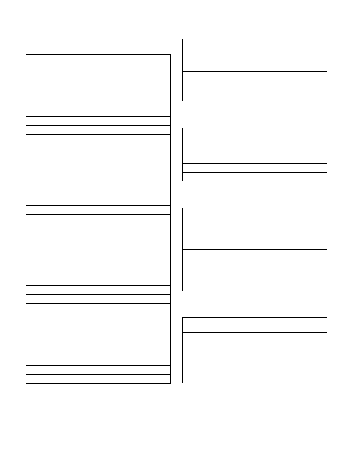
Settings Affected by INIT, SAVE, and LOAD
Commands
The following commands apply to camera setting data.
Command Remarks
AE-MODE INIT initializes to fixed value.
AGCMAX-STEP INIT initializes to fixed value.
AGCMAX-FINE INIT initializes to fixed value.
CCDIRIS-MAX INIT initializes to fixed value.
SSHUTTER-MAX INIT initializes to fixed value.
AE-SPEED INIT initializes to fixed value.
AE-REF INIT initializes to fixed value.
GAIN-STEP INIT initializes to fixed value.
GAIN-FINE INIT initializes to fixed value.
SHUTTER INIT initializes to fixed value.
WB-MODE INIT initializes to fixed value.
RGAIN INIT initializes to factory default value.
BGAIN INIT initializes to factory default value.
ATW-SPEED INIT initializes to fixed value.
CRS-MODE INIT initializes to fixed value.
DTL-MODE INIT initializes to fixed value.
DTL-ENHANCER INIT initializes to fixed value.
2DNR-MODE INIT initializes to fixed value.
3DNR-MODE INIT initializes to fixed value.
PEDESTAL INIT initializes to fixed value.
GAMMA-MODE INIT initializes to fixed value.
NEGAPOSI INIT initializes to fixed value.
WHITECLIP INIT initializes to fixed value.
WPC-MODE INIT initializes to fixed value.
OPD-DISP INIT initializes to fixed value.
OPD-AE-POS INIT initializes to fixed value.
OPD-AE-SIZE INIT initializes to fixed value.
OPD-AWB-POS INIT initializes to fixed value.
OPD-AWB-SIZE INIT initializes to fixed value.
VOUTSEL INIT initializes to fixed value.
HPHASE INIT initializes to factory default value.
VPHASE INIT initializes to factory default value.
COLORBAR INIT initializes to fixed value.
FLIP INIT initializes to fixed value.
OSD INIT initializes to fixed value.
MEMO-DISPLAY INIT initializes to fixed value.
Setting Value Initialization
Command
Name
Parameter None
Conditions None
Process Returns the camera’s user memory to its
Remarks The communication speed is not initialized.
INIT
factory default state.
The last loaded user memory is not changed.
Setting Value Saving
Command
Name
Parameter 1 User memory save destination: 0 to 1
Conditions None
Process Writes to user memory A or B.
SAVE
0: User memory A
1: User memory B
Setting Value Loading
Command
Name
Parameter 1 Load original user memory: 0 to 2
Conditions None
Process Loads user’s camera control command
LOAD
0: User memory A
1: User memory B
2: Stand-alone user memory
settings, and saves them as the last loaded
user memory selection information. These
user memory settings are loaded the next
time the camera is turned on.
View Setting Values
Command
Name
Parameter None
Conditions None
Process Sends all data that can be set with camera
RMEM
information.
The setting value of each camera control
command is displayed one command per
line, with comma separators.
Camera Control Commands
25
Page 26
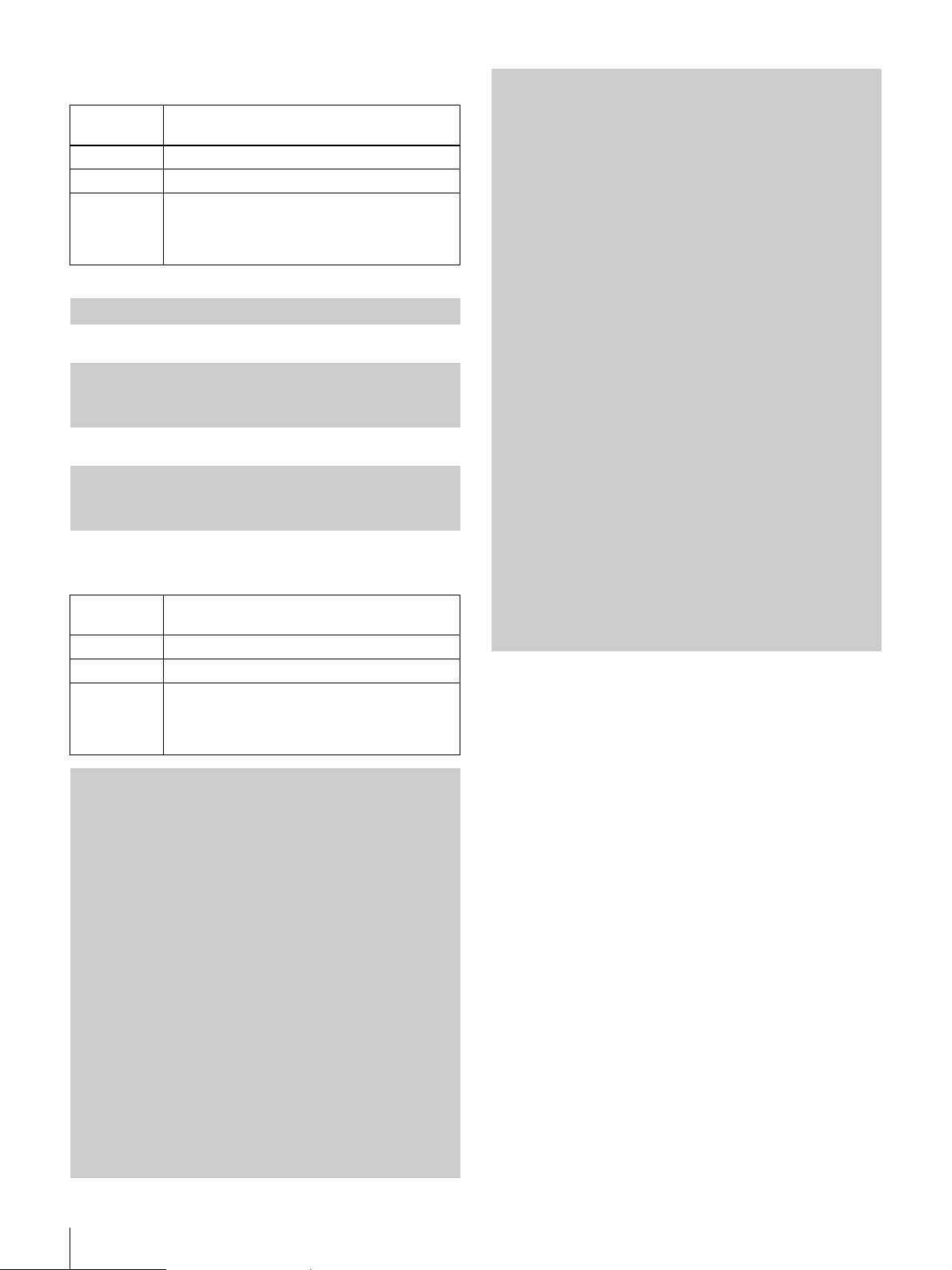
Version Display
Command
Name
Parameter None
Conditions None
Process Displays the following items:
<<Input>>
VERSION<CR>
<<Screen Output Example (NTSC)>>
XC-505<CR><LF>
Version 1.00<CR><LF>
S/N 100001<CR><LF>
<<Screen Output Example (PAL)>>
XC-505P<CR><LF>
Version 1.00<CR><LF>
S/N 100001<CR><LF>
VERSION
• Camera model name
• Firmware version
• Serial number
Help Display
Command
Name
Parameter 1 Command Name
Conditions None
Process Display help for the command specified by
HELP
parameter 1.
If parameter 1 is omitted, displays the list of
usable commands.
2DNR-MODE,
3DNR-MODE,
PEDESTAL,
GAMMA-MODE,
NEGAPOSI,
WHITECLIP,
WPC-MODE,
WPC-DISP,
WPC-EXE,
OPD-DISP,
OPD-AE-POS,
OPD-AE-SIZE,
OPD-AWB-POS,
OPD-AWB-SIZE,
VOUTSEL,
HPHASE,
VPHASE,
COLORBAR,
FLIP,
BRATE,
OSD,
MEMO-CAPTURE,
MEMO-DISPLAY,
INIT,
SAVE,
LOAD,
RMEM,
VERSION,
HELP
OK
HELP
AE-MODE,
AGCMAX-STEP,
AGCMAX-FINE,
CCDIRIS-MAX,
SSHUTTER-MAX,
AE-SPEED,
AE-REF,
GAIN-STEP,
GAIN-FINE,
SHUTTER,
SSHUTTER,
WB-MODE,
AUTOWB,
RGAIN,
BGAIN,
ATW-SPEED,
CRS-MODE,
PICTURE,
DTL-MODE,
DTL-ENHANCER,
26
Camera Control Commands
Page 27
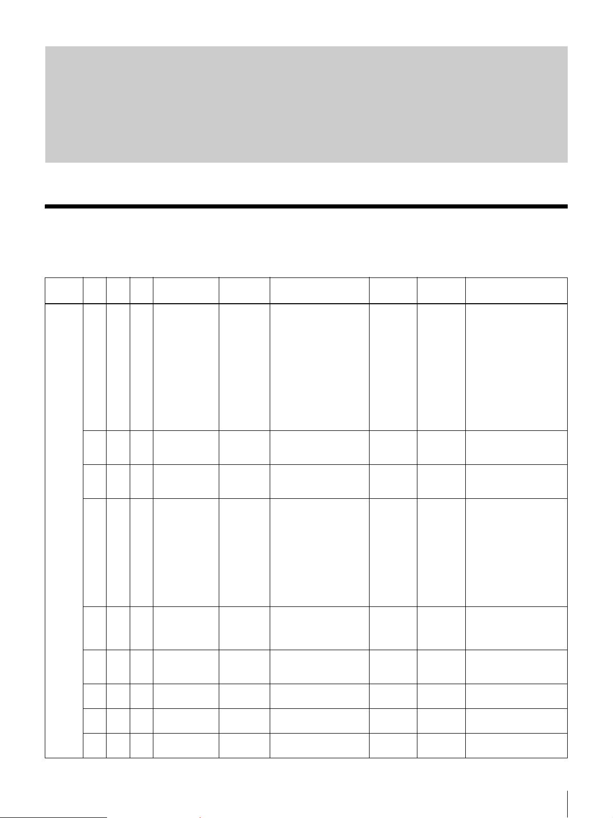
Camera Control Command List
For parameters 1 and 2, numerical values in parenthesis ( ) indicate default values.
INIT
SAVE
Category
AE aa × Auto exposure
Object
aa × Max. auto
aa × Max. auto
aa × Electronic
aa × Slow shutter
aa × AE
aa × AE Reference
aa × Gain setting
aa × Gain setting
Object
Auto
Save
mode setting
gain control
setting (dB)
gain control
setting (step)
shutter max.
adjustment
value
max.
adjustment
value
Convergence
Speed Setting
Level Setting
(dB)
(step)
Command
Command
String
AE-MODE Mode0 to 5 (2)
AGCMAXSTEP
AGCMAXFINE
CCDIRISMAX
SSHUTTE
R-MAX
AESPEED
AE-REF Refarence Level
GAINSTEP
GAINFINE
Parameter 1
0 : Fixed electronic
shutter
1 : Fixed electronic
shutter
+ fixed gain
2 : Fixed electronic
slow shutter
+ fixed gain
3 : CCD IRIS
4 : CCD IRIS
+ Auto slow shutter
5 : CCD IRIS + AGC
dB units
6 to 18 (18)
Step units
22 to 67 (67)
Preset Number
0 to 8 (5)
0 : 1/100s
1 : 1/120s
2 : 1/250s
3 : 1/500s
4 : 1/1000s
5 : 1/4000s
6 : 1/10000s
7 : 1/50000s
8 : 1/100000s
Frame count
1 to 255 (6)
Speed (Slow/Normal/
Fast)
0, 1, 2 (1)
0 to 1023 (120)
dB units
–3 to 18 (0)
Step units
–79 to 474 (0)
Appendix
Parameter 2 Parameter
××
× × AGCMAX-STEP and
× × AGCMAX-STEP and
××
××
××
××
× × GAIN-STEP and GAIN-
× × GAIN-STEP and GAIN-
3
Remarks
AGCMAX-FINE values
are linked
AGCMAX-FINE values
are linked
FINE values are linked
FINE values are linked
Camera Control Command List
27
Page 28
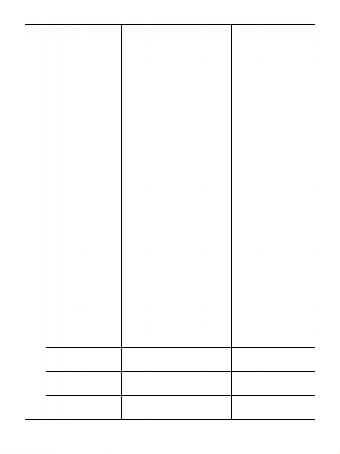
INIT
SAVE
Category
AE aa ×Fixed
Object
Object
Auto
Save
electronic
shutter speed
Command
Command
String
SHUTTER Preset Number
Parameter 1
NTSC (0)
0 : 1/60s
1 : 1/100s
2 : 1/120s
3 : 1/250s
4 : 1/500s
5 : 1/1000s
6 : 1/2000s
7 : 1/4000s
8 : 1/10000s
9 : 1/50000s
10 : 1/100000s
PA L( 0 )
0 : 1/50s
1 : 1/100s
2 : 1/120s
3 : 1/250s
4 : 1/500s
5 : 1/1000s
6 : 1/2000s
7 : 1/4000s
8 : 1/10000s
9 : 1/50000s
10 : 1/100000s
11 0 to 261
Parameter 2 Parameter
Arbitrary
Parameter
1
NTSC
0 to 311
PA L
Arbitrary
Parameter
2
××
0 to 910
NTSC
0 to 908
PA L
3
Remarks
NTSC
When parameter 2 is 0,
the range for
parameter 3 is 143 to
910.
Fixed
electronic
slow shutter
speed
WB aa × White balance
mode setting
×××One Push
white balance
execution
aa × Manual R gain RGAIN Step units
aa × Manual B gain BGAIN Step units
aa ×ATW
Entrainment
speed
adjustment
PA L
When parameter 2 is 0,
the range for
parameter 3 is 142 to
908.
SSHUTTER
WBMODE
AUTOWB × × × Only when WB-MODE
AT WSPEED
0 to 255 (3) NTSC
0 to 255 (3) PAL
One Push/ATW/
Manual/3200K/5600K
0,1,2,3,4(1)
0 to 4095 (factory)
0 to 4095 (factory)
Speed (Slow/Normal/
Fast)
0,1,2 (1)
0 to 524
(0) NTSC
0 to 624
(0) PAL
××
× × Only when WB-MODE
× × Only when WB-MODE
××
×NTSC
When parameter 1 is 0,
the range for
parameter 2 is 262 to
524.
PA L
When parameter 1 is 0,
the range for
parameter 2 is 312 to
624.
= 0
= 2
Default R gain is
3200 [K].
= 2
Default B gain is
3200 [K].
28
Camera Control Command List
Page 29
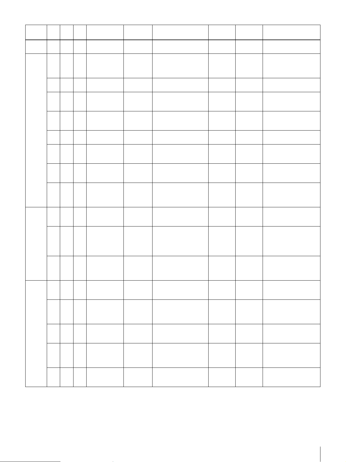
INIT
SAVE
Category
WB aa × Switch CRS
PICTURE
WPC aa× White point
OPD a ××Detection
Object
aa ×Contour
aa × Detail
aa × 2-D noise
aa × 3-D noise
aa × Pedestal
aa ×Gamma
aa × Positive-
aa ×High
×××Auto white
a × × White point
aa × AE frame
aa × AE frame
aa × AWB frame
aa × AWB frame
Object
Auto
Save
during ATW
emphasis
mode
enhancer
reduction
setting
reduction
setting
adjustment
compensation
setting
negative
reverse
Brightness
Clipping
Setting
detection
mode
point
detection
compensation
execution
compensation
position
default is 0
frame display
switching
center
coordinates
width and
height
center
coordinates
width and
height
Command
Command
String
CRSMODE
DTLMODE
DTLENHANCER
2DNRMODE
3DNRMODE
PEDESTAL
GAMMAMODE
NEGAPOSI
WHITECLIP
WPCMODE
WPC-EXE × × × Execute with the lens
WPCDISP
OPD-DISP Off/AE/WB
OPD-AEPOS
OPD-AESIZE
OPDAWB-POS
OPDAWB-SIZE
Parameter 1
Mode (Off/On)
0,1 (0)
MODE
(Off, V, H, V+H,
Highlight)
0,1,2,3,4 (2)
Mode (Off/On)
0,1 (0)
Off, Mild, Moderate,
Strong
0,1,2,3 (1)
Off, Mild, Moderate,
Strong
0,1,2,3 (0)
Step units
0 to 22 (11)
Off/γ = 0.45/γ = 0.60
0,1,2 (1)
Positive/Negative
0,1 (0)
Step units
0 to 63 (63)
Mode (Off/On)
0,1 (1)
OFF/ON
0,1 (0)
0,1,2 (0)
x-coordinate
25 to 75 (50)
width
50 to 100 (50)
x-coordinate
25 to 75 (50)
width
50 to 100 (50)
Parameter 2 Parameter
× × Only when WB-MODE
××
××
××
××
××
××
××
××
××
× × Displays only when
××
y-
coordinate
25 to 75
(50)
height
50 to 100
(factory)
y-
coordinate
25 to 75
(50)
height
50 to 100
(50)
3
= 1
covered, such as by a
lens cap.
WPC-MODE is 1.
×
×
×
×
Remarks
Camera Control Command List
29
Page 30
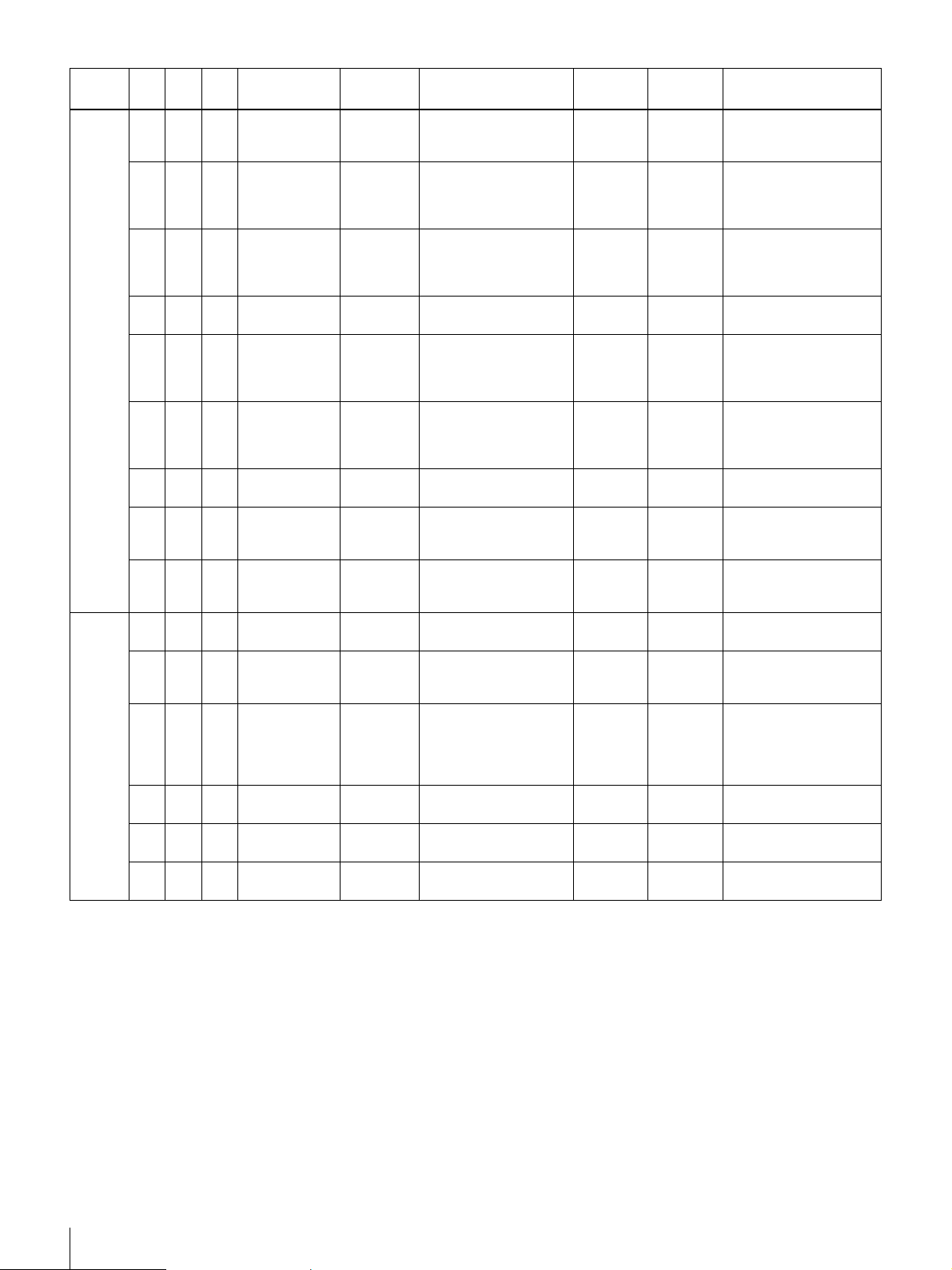
INIT
SAVE
Category
I / O aa × VBS/YC
Miscellaneous
Object
aa ×Horizontal
aa × Vertical phase
a × × Color bar
aa ×Reverse
××a
aa × OSD Display OSD Off/On
× × × Screen memo
a × × Memo Display MEMO-
× × × Setting Value
× × × Setting Value
××a Load settings
× × × Read setting
×××Version
× × × Help Display HELP Command Name
Object
Auto
Save
Output
Selection
phase
adjustment
adjustment
output
image display
Serial
communication
speed
changing
saving
Initialization
Saving
from
destination
upon next
restart
values
Display
Command
Command
String
VOUTSEL VBS or separate Y/C
HPHASE Adjustment Step
VPHASE Adjustment Step
COLORBAR
FLIP Reverse mode
BRATE Baud rate selection
MEMOCAPTURE
DISPLAY
INIT × × ×
SAVE Save destination
LOAD Load source selection
RMEM × × ×
VERSION × × ×
Parameter 1
0,1(0)
0 to 910 (factory)
NTSC
0 to 908 (factory) PAL
0 to 262 (factory)
NTSC
0 to 312 (factory) PAL
Off/On
0,1 (0)
(None, horizontal,
vertical, 180 deg.)
0,1,2,3 (0)
(9600/19200/38400)
0,1,2 (2)
0,1
Save destination
(0 or 1)
0,1 (0)
Off/still/memo1/
memo2
0,1,2,3 (0)
selection (A or B)
0,1
(A, B, or stand-alone)
0,1,2 (2)
string
Parameter 2 Parameter
××
××
××
××
××
××
××
× × Saving is possible with
××
××
× × Subsequently starts
× × Lists commands when
3
Remarks
still image displayed
from last loaded slot
parameter 1 is omitted
30
Camera Control Command List
Page 31

Specifications
Photographic Components
Image sensor 1/3-type interline transfer CCD
Color filter Complementary color mosaic
Effective pixels XC-505:
Approx. 380,000 dots (768 [H] × 494
[V])
XC-505P:
Approx. 440,000 dots (752 [H] × 582
[V])
Video output pixels
XC-505: 756 [H] × 485 [V]
XC-505P: 739 [H] × 575 [V]
Cell size XC-505: 6.35 [H] × 7.40 [V] µm
XC-505P: 6.50 [H] × 6.25 [V] µm
Output connector
12-pin DC IN, SYNC, and VIDEO
External VS (sync) input
Input level XC-505:
Video signal = 0 Vpp to 1.4 Vpp
CSYNC signal = 0.15 Vpp to 0.6 Vpp
XC-505P:
Video signal = 0 Vpp to 1.4 Vpp
CSYNC signal = 0.15 Vpp to 0.6 Vpp
Horizontal input frequency
XC-505: 15734 Hz ±0.236 Hz
XC-505P: 15,625 Hz ±0.234 Hz
Vertical input frequency
XC-505: 59.94 Hz ±0.00089 Hz
XC-505P: 50 Hz ±0.00075 Hz
Termination Camera-internal 75 Ω
H jitter 20 ns or less
Optics & Miscellaneous
Lens mount Dedicated (NF) mount
Signal format XC-505: EIA standard NTSC color
XC-505P: CCIR standard PAL color
Scan format XC-505: 525 lines, 2:1 interlace,
30 frames/s
XC-505P: 625 lines, 2:1 interlace,
25 frames/s
Sync method Internal or external (auto-switching)
External sync input
HD/VD or VS
Horizontal resolution
XC-505: 470 TV lines
XC-505P: 460 TV lines
Minimum illumination
1.5 lx (F1.4, AGC: ON)
Sensitivity 2000 lx (F11, AGC: OFF [0 dB])
Video output VBS or Y/C (switch-selectable)
VBS: 1 Vp-p, 75 Ω, negative sync
Y: 1 Vp-p, 75 Ω
C: composite video output dependent
Video S/N XC-505: 48 dB (standard), AGC: OFF
(0 dB)
XC-505P: 46 dB (standard), AGC: OFF
(0 dB)
Shutter speed (4 modes)
1/60 s (OFF): XC-505
1/50 s: XC-505P (OFF), 1/1000 s,
CCD IRIS, and Flickerless (1/00)
CCD IRIS XC-505: 1/60 s to 1/4000 s
XC-505P: 1/50 s to 1/4000 s
White balance (5 modes)
ATW, One Push WB, 3200K, 5600K,
and MAN
Gain control (2 modes)
AGC (0 dB to 18 dB), and fixed (0 dB)
External HD/VD sync input
Input level same for XC-505 and XC-505P
High: 4.0 V to 5.0 V DC
Low: 0V to 0.5V DC
Negative polarity
HD input frequency
XC-505: 15734 Hz ±0.236 Hz
XC-505P: 15,625 Hz ±0.234 Hz
VD input frequency
XC-505: 59.94 Hz ±0.00089 Hz
XC-505P: 50 Hz ±0.00075 Hz
Termination Camera-internal 75 Ω
H jitter 20 ns or less
General
Power requirement
10.5 V to 15 V DC
Power consumption
1.5 W
Operating temperature
0°C to 40°C (32°F to 104°F)
Storage temperature
–30 °C to +60 °C (–22 °F to +140 °F)
Operating humidity
20% to 80% (non-condensing)
Storage humidity
20% to 90% (non-condensing)
Shock resistance
70 G
MTBF 81,880 hours (approx. 9.3 years)
Physical characteristics
Mass Approx. 51 g (1.8 oz)
Specifications
31
Page 32
Dimensions 22 (W) × 22 (H) × 64 (D) mm
7
(
/8 (W) × 7/8 (H) × 25/8 (D) inches)
(excluding protrusions)
Supplied accessories
Lens mount cap (1)
Tripod adaptor (1 set)
Operating Instructions (1)
Optional accessories
Camera adaptor
DC-700, DC-700CE
Compatible lenses
NF-mount
VCL-12S12XM (f=12 mm)
VCL-06S12XM (f=6 mm)
VCL-03S12XM (f=3.5 mm)
C-mount LO-999CMT
Cable (12-pin) CCXC-12P02N (2 m)/12P05N (5 m)/
12P10N (10 m)/12P25N (25 m)
Angle case kit XCK-L555
Design and specifications are subject to change without
notice.
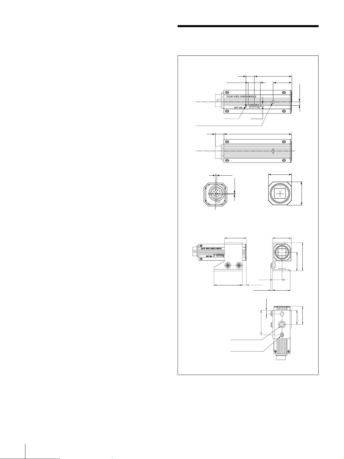
Dimensions
15
11.25 (
3
/32)
φ 2 (
4 sides φ 2.5 (3/32) countersunk, deapth 1
8 (11/32)
Rear Front
1.2 (1/16)
1
)
16
/
1.2 (
7.8 (5/16)
/32)
2 (3/32)
64 (2
5/8)
35.2 (1
7
/16)
17.4 (
22 (7/8)
11
/16)
)
32
/
5
3.25 (
)
8
/
7
22 (
Units: mm (inches)
With the tripod adaptor (supplied accessory) installed
29.4 (13/16)
1
38 (1
/2) 5.4 (7/32)
Tripod screw hole
1/4"–20 UNC
– 4.1×6
2
12.6 (1/2)
(2.5 (
5
Long hole
1
)
16
/
33 (1
/8))
7
)
32
/
5 (
25.1 (1)
23.6 (15/16)
25 (1)
)
4
/
3
19 (
Units: mm (inches)
)
2
/
1
37.9 (1
)
32
/
31
24.4 (
32
Dimensions
Page 33
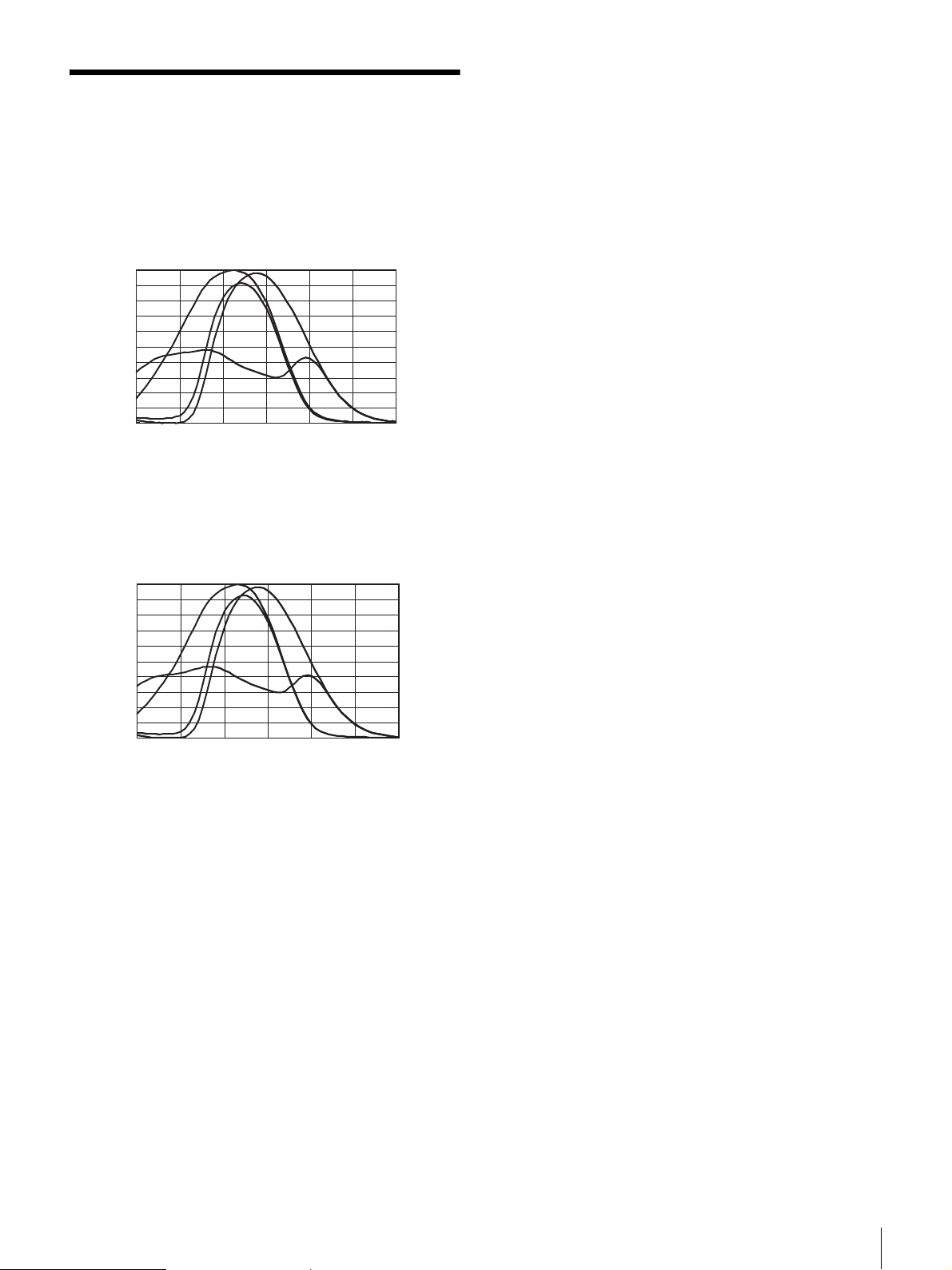
Spectral Sensitivity Characteristics (typical)
XC-505
Relative sensitivity
1.0
0.8
0.6
0.4
0.2
0
400 450 500 550 600 650 700
XC-505P
Relative sensitivity
1.0
0.8
0.6
0.4
Cy
Mg
Ye
Gr
Wavelength (nm)
Cy
Ye
Mg
0.2
Gr
0
400 450 500 550 600 650 700
Wavelength (nm)
Characteristics of the lens and light source are excluded.
Spectral Sensitivity Characteristics (typical)
33
Page 34

Sony Corporation
 Loading...