How it Works
Log In / Sign Up
Buy Points
How it Works
FAQ
Contact Us
Questions and Suggestions
Users
Sony
Loading...
X
XA1
XA1 G3221
XA1 G3223
XA43M61
XA43M91
XA5400ES
XA-AC13
XAC-30
5
XA-C30 - 2 Output Selector
XA-C40
XA-CA660X
XACC-1
3
XA-DC1
XA-DC3
XA-MC10
7
XA-NV100T
3
XA-NV300T
6
XA-NV400
3
XA-R800C
3
XA-T7
XAU-20
XAU-40
XAU-400
XA-U40D
2
XAV-1500
14
XAV-1550D
7
XAV-3500
12
XAV-3550ANT
XAV-3550D
4
XAV-60
21
XAV-601BT
25
XAV-602BT
30
XAV-612BT
11
XAV-622
18
XAV-62BT
18
XAV-63
36
XAV-64BT
24
XAV-65
30
XAV-68BT
26
XAV-701BT
11
XAV-701HD
8
XAV-70BT
23
XAV-70BT Marketing
XAV-712BT
12
XAV-712HD
6
XAV-722
XAV-72BT
27
XAV-741
13
XAV-742
6
XAV-77
2
XA-V7M
XA-V7W
12
XAV-9500ES
3
XAV-A1
7
XAV-A1 RU
XAV-AX100
27
XAV-AX1000
14
XAV-AX1000-Q
XAV-AX1005DB
3
XAV-AX100-C
XAV-AX100C2
11
XAV-AX150
2
XAV-AX200
16
XAV-AX200C2
2
XAV-AX205ANT
XAV-AX205DB
13
XAV-AX210
4
XAV-AX3005DB
6
XAV-AX3200
2
XAV-AX3250
5
XAV-AX4000
2
XAV-AX5000Q2
XAV-AX5110
4
XAV-AX5160
XAV-AX5500
6
XAV-AX5550D
7
XAV-AX5600
2
XAV-AX5650
5
XAV-AX6000
XAV-AX7000
5
XAV-AX8050D
4
XAV-AX8100
3
XAV-AX8150
3
XAV-C1
11
XAV-C1 RU
XAV-E60
4
XAV-E622
4
XAV-E62BT
3
XAV-E70BT
2
XAV-E722
3
XAV-V10BT
14
XAV-V630BT
20
XAV-V631BT
5
XAV-V750BT
4
XAV-V751BT
XAV-W1
20
XAV-W60
XAV-W600
2
XAV-W600-C
XAV-W601
5
Loading...
Loading...
Nothing found
XAV-742
Installation Guide
2 pgs
285.37 Kb
0
Operating Instruction
48 pgs
1.07 Mb
0
User manual
52 pgs
1.46 Mb
0
User Manual [ru]
112 pgs
2.12 Mb
0
Users guide
2 pgs
506.33 Kb
0
Users guide
44 pgs
1.35 Mb
0
Table of contents
Loading...
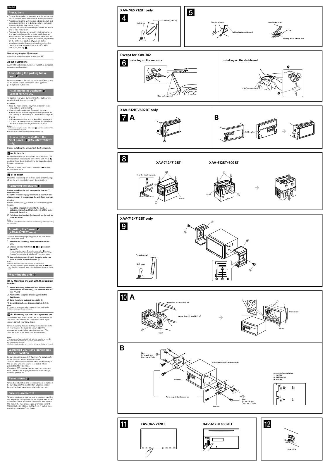
Sony XAV-742, XAV-712BT, XAV-612BT Installation Guide
...
Sony Installation Guide
Download
Specifications and Main Features
Frequently Asked Questions
User Manual
Download
Page 1
Page 2
Loading...
+
hidden pages
Unhide
You need points to download manuals.
1 point = 1 manual.
You can buy points or you can get point for every manual you upload.
Buy points
Upload your manuals
 Loading...