

Page 1
3-206-989-13 (1)
UHF Synthesized
Transmitter
Operating Instructions
Precautions
• The unit is designed for use in ambient temperature
range of 0°C to 50°C (32°F to 122°F).
• Do not place the unit on or near heat sources, such
as lighting equipment, power amplifiers, or in a
place subject to direct sunlight or excessive
moisture. In such places, the external finish or
internal parts of the unit may be damaged.
• If the unit is used in a very humid or dusty place or
in a place subject to expose to an active or corrosive
gas, clean its surface as well as the connectors with a
dry, soft cloth soon after use.
Specifications
Lengthy use of the unit in such places or not
cleaning it after its use in such places may shorten
its life.
• When cleaning the unit, never use organic solvents
such as thinners or benzine, which will damage the
finish of the unit.
• The unit has been factory adjusted precisely. Do not
tamper with its internal parts or attempt to repair it.
WRT-8B
Sony Corporation 2002 Printed in Japan
Owner’s Record
The model and serial numbers are located at
the rear of the unit. Record the serial number in
the space provided below. Refer to these
numbers whenever you call upon your Sony
dealer regarding this product.
Model No. WRT-8B Serial No.____________
Notice for customers in the
U.S.A.
Use of Sony wireless devices is regulated by the
Federal Communications Commission as
described in Part 74 subpart H of the FCC
regulations and users authorized thereby are
required to obtain an appropriate license.
You are cautioned that any changes or
modifications not expressly approved in this
manual could void your authority to operate this
equipment.
IMPORTANT NOTE: To comply with the FCC
RF exposure compliance requirements, no
change to the antenna or the device is
permitted. Any change to the antenna or the
device could result in the device exceeding the
RF exposure requirements and void user’s
authority to operate this device.
Notice for customers in Canada
Use of Sony wireless devices is regulated by the
Industry Canada as described in their Radio
Standard Specification RSS-123.
A licence is normally required. The local district
office of Industry Canada should therefore be
contacted. When the operation of the device is
within the broadcast band, the licence is issued
on no-interference, no-protection basis with
respect to broadcast signals.
Operation of this device is subject to the
following two conditions: (1) this device may not
cause interference, and (2) this device must
accept any interference, including interference
that may cause undesired operation of the
device.
The term “IC:” before the radio certification
number only signifies that Industry Canada
technical specifications were met.
Hereby, Sony Corporation, declares that this
WRT-8B is in compliance with the essential
requirements and other relevant provisions of
Directive 1999/5/EC.
Note:
In some countries additional frequency bands
may be used with the agreement of the national
authority.
Note for customers in Austria:
Before use, it is necessary to obtain individual
permission of the local telecommunications
spectrum authority.
Note for customers in Switzerland:
Before use, a request of concession for a
wireless microphone (Frequency Class 3) has to
be submitted to Bakom.
Note for customers in Finland:
To own and use, it is necessary to obtain an
individual licence of the Telecommunications
Administration Center.
Note for customers in Luxembourg:
Before any use of an equipment, the frequencies
required have to be, if necessary according to
the regulations in force, assigned prior to usage
by the “ILT”.
Note for customers in Italy:
The use of this product within Italy is subject to
article 334 of the Postal and
Telecommunications regulations.
Nota per i clienti in Italia:
L’uso del prodotto sul territorio italiano è
soggetto alle regolamentazioni del Codice
Postale e delle Telecomunicazioni art. 334.
Note for customers in Belgium:
Using this transmitter with 50 mW RF output
power is not allowed. Be sure to set the RF
output power to 10 mW.
Note for customers in Norway:
Using this transmitter with 50 mW RF output
power requires the frequency license.
Transmitter and modulator section
Oscillator Crystal controlled PLL
Carrier frequencies Model available in USA:
Operating frequency band
RF power output 50 mW/10 mW e. r. p.
Tone signal 32.768 kHz
Battery condition signal
Type of antenna
Pre-emphasis 50 µs
Deviation ±5 kHz
Maximum deviation ±40 kHz
Frequency response
Signal-to-noise ratio
............................................................................................
0 dBv = 1 Vrms
synthesizer
758 to 806 MHz
Model available in Europe:
470 to 606 MHz
614 to 862 MHz
Model available in Australia:
792 to 806 MHz
Model available in USA and
Europe:
24 MHz
Model available in Australia:
14 MHz
Refer to the “Sony Wireless
Microphone System Frequency
List” supplied with this manual.
32.782 kHz
1
/4 -wavelength wire
(–60 dBV, 1 kHz input, MIC)
±5 kHz
(–20 dBu, 1 kHz input, LINE)
40 to 20,000 Hz
60 dB or more (A-weighted,
modulation frequency 1 kHz,
with ±5 kHz deviation at tuner)
Power section
Power requirements
3.0 V DC (two LR6/size AA
Battery life Approx. 6 hours at 25°C
alkaline batteries)
(77°F) with Sony LR6 alkaline
batteries (50 mW)
Approx. 13 hours at 25°C
(77°F) with Sony LR6 alkaline
batteries (10 mW)
General
Operating temperature
Storage temperature
Dimensions 63 × 83 × 17 mm (w/h/d)
Mass Approx. 140 g (4.9 oz)
0°C to +50°C (32°F to 122°F)
–30°C to +60°C
(–22°F to +140°F)
1
/2 × 3 3/8 × 11/16 inches)
(2
including batteries
Supplied accessories
Operating Instructions (1 set)
Sony Wireless Microphone System Frequency List (1)
Soft case (1)
Scribble sheet (supplied with European model only)
(1)
Battery case (1)
Microphone cable (1)
Optional accessories
Lavalier microphones
ECM-44BC, ECM-77BC, ECM-166BC, ECM310BC, ECM-350BC
Design and specifications are subject to change
without notice.
Error Messages
When a problem occurs, one of the following error message may appear on the display.
Messages
ERROR 11
ERROR 21
ERROR 31
Contents
An error occurred in backup memory data.
The PLL synthesized circuit is in trouble.
The battery voltage exceeds the allowable value.
Measures
Turn the transmitter OFF, then turn it
ON again to clear the backup memory.
Channel group is reset to 00
(European model only), channel is
reset to 01, and RF output power is
reset to H, respectively.
Turn the transmitter OFF, then turn it
ON again. If it does not work, contact
your Sony dealer.
Use the specified batteries.
Notice for customers in Europe
U.K. 854.125 - 862 MHz
Germany
798 - 822 MHz
Norway 800 - 820 MHz
Luxembourg
800 - 830 MHz, 854.125 - 862 MHz
Belgium 854.125 - 862 MHz
Denmark
800.100 - 819.900 MHz
France 470 - 830 MHz
Italy 800 - 820 MHz
Sweden 800 - 820 MHz
Switzerland
800 - 820 MHz
Finland 800 - 814 MHz
Iceland 800 - 814 MHz
Austria 774 - 790 MHz
Netherlands
774 - 782 MHz
Overview
The WRT-8B is a transmitter for a UHF synthesized
wireless microphone system to be used for broadcast
or movie production purpose. This transmitter is
suitable for Electronic News gathering (ENG) and
Electronic Field Production (EFP).
The microphone/transmitter and tuner of the wireless
microphone system are classified by frequency band.
A 24-MHz (USA and Europe)/14-MHz (Australia)
frequency band is assigned to each microphone/
transmitter and tuner model. In building a UHF
wireless microphone system, be sure to combine a
microphone/transmitter and a tuner having the same
wireless channel (frequency).
Features
The features of the WRT-8B are:
–Phase Locked Loop (PLL) synthesized system
–Compact and lightweight
–Selectable RF power output: 50 mW and 10 mW
–Switchable input level and variable attenuator
–Remote battery alarm on tuner
–Operation powered by easily available batteries
–LCD for coordinated operation control
–Compatibility with Sony lavalier microphone
–RF carrier with tone signal
–Wide dynamic range and low noise
Notes on Microphone System Operation
To operate with two or more channels, maintain a
•
distance of at least 30 cm (one ft.) between each pair
of transmitters.
For details of operation with two or more channels,
refer to the Operating Instructions for the WRR-802/
805/855/862, or WRU-8N with MB-8N, etc.
Ensure that the tuners set to channels not being used
•
are either turned off or set to the minimum output
level.
When powering the transmitter on or off, to keep the
•
noise to a minimum, set the audio output level from
the tuner or mixer to a minimum.
Powering the transmitter on without checking the
•
channel selection first may interfere with the
operation of other microphones/transmitters, if the
current setting is already being used.
To prevent noise generation, set the RF power
•
output to L (10 mW) when multiple channels are
used simultaneously, and keep the microphones and
transmitters at least 3 m (10 feet) away from the
antennas when the system is operated using a group
which allows selection of up to 8 channels, and at
least 6 m (20 feet) away when using a group which
allows selection of 9 channels.
For details on how to set the RF output power, see
“Changing the RF Output Power” on the reverse
side.
When there is a strong interference signal around the
•
microphone system, such as an interference caused
by an active handyphone, noise may occur on the
microphone system.
Page 2
Parts Identification
Wire
antenna
7
1
4
+
–
5
6
3
8
2
Battery
holder
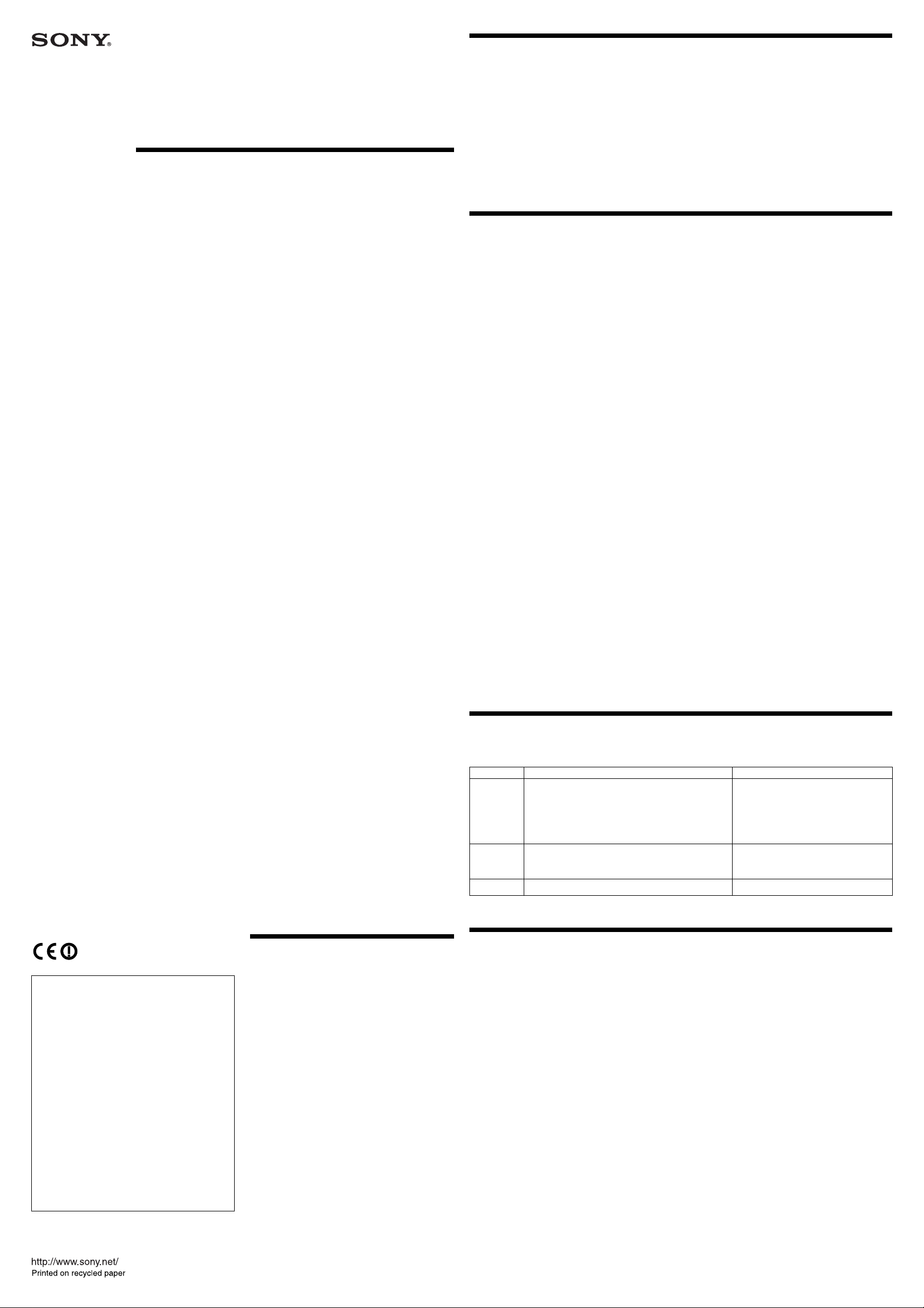
1 LCD (liquid-crystal display) display
C
D
B
A
Channel indication E
shows that of the U66
model.
AF RF BATT
E
H
L
A AF (audio input) indication
Appears whenever an audio signal stronger than the
reference level is received.
B RF (antenna output) indication
Appears during signal transmission from the antenna.
C RF power indication
Shows the RF output power setting.
See “Changing the RF Output Power.”
D BATT (battery) indication
Shows the battery condition.
See “Battery indication” in “Power Supply” section.
E CH (channel) indication
Shows transmitting channel.
Each time you press the SET button in Transmitting
mode, the channel indication changes as follows.
Transmitting
channel
Transmitting
frequency
Accumulated
battery use
time
Channel/frequency indications show those of the
U66 model.
Transmitting channel: The current transmitting
channel setting.
Transmitting frequency: The current transmitting
fequency setting.
Press SET
button.
Power Supply
The transmitter can operate on two LR6 (size AA)
alkaline batteries continuously for about 6 hours at
25°C (77°F).
Accumulated battery use time: The accumulated
time of battery use (in one-minute increments).
2 + (+ selection) / – (– selection/reset)
buttons
In setting mode, select the transmission channel,
frequency and RF output power setting using either of
these buttons, or reset the time-of-use indication to
“00:00” with the – button.
3 Audio input connector
Connect the output connector of the following Sony
lavalier microphones: ECM-44BC, ECM-77BC,
ECM-166BC, ECM-310BC, ECM-350BC, etc.
You can also use your wired microphone by
connecting it to this connector with a microphone
cable.
Microphone (not supplied)
To secure the microphone cable connection,
be sure to turn and lock the connector cover.
Caution
When connecting a microphone to the unit, be sure to
turn the unit off.
4SET button
• In Transmitting mode, press this button to change
the indicated items in the lower half of the LCD
display.
• The SET button is also used to enter the Setting
mode and select the item to be set.
5 POWER switch
Turns the transmitter ON or OFF.
Note
Be sure to connect a microphone before turning the
power ON.
6 AF LEVEL control
Adjusts the audio level from the audio input
connector.
7 PEAK indicator
Lights up when the input signal level is too high.
8 MIC/LINE select switch
Set according to the equipment connected to the audio
input connector.
For details, on the use of this switch, see “Adjusting
the Audio Input Level.”
12 34
BATT
indication
Battery
condition
Lights Lights Flashes Goes off
Good Less than
halfcharge
Almost
exhausted
Completely
exhausted
Settings
For the transmitting channels and frequencies
selectable on your transmitter, see the “Sony Wireless
Microphone System Frequency List” supplied with
this manual.
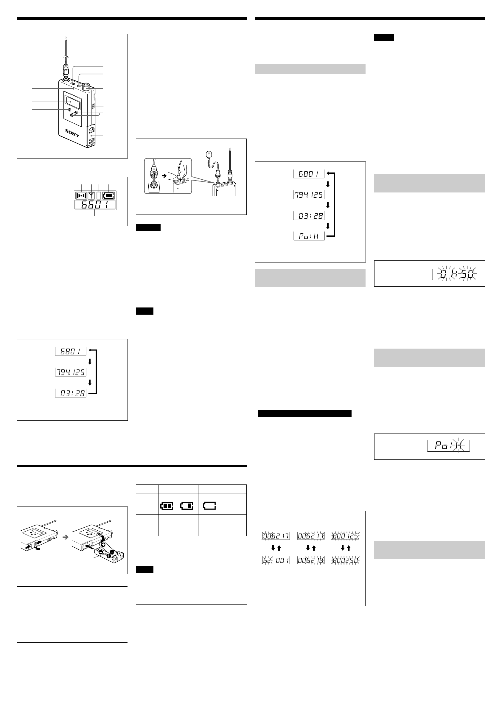
Initiating Setting Mode
In Setting mode, you can change the transmission
channel/frequency and the RF output power level, or
reset the accumulated time indication.
To enter Setting mode
While holding down the SET button, set the POWER
switch to ON.
The transmitter enters Setting mode and the indication
before the transmitter was previously turned OFF
flashes on the display section.
Each time you press the SET button, the setting items
are cyclically switched as shown below.
Transmitting
channel
Transmitting
frequency
Press SET
Accumulated
battery use
time
RF output
power
Channel/frequency indications show those of the
U66 model.
Changing the Transmitting
Channel
The transmitting channel can be selected through
either the channel number or the frequency.
1 Set the transmitter to Setting mode.
If the channel number (or frequency) indication
does not appear, press the SET button until the
channel number (or frequency) indication appears.
2 Press the + or – button to select the channel
number (or frequency).
Pressing the + button cycles the indication in the
order shown in the tables in the “Sony Wireless
Microphone System Frequency List” supplied with
the manual. Pressing the – button cycles the
indications in the opposite direction.
Hold down the button to change the channel
number (or frequency) quickly.
Note on the model available in Europe
On the model available in Europe, the transmitting
channels are grouped in four sets.
Select the group number before selecting the
channel number as follows.
1)When the left two digits flash, select the group
number by pressing the + or – button.
2)When the desired group number appears, press
the SET button.
The right four digits start to flash for channel
number selection.
3)Select the channel number by pressing the + or –
button.
4)When the desired channel number appears, press
the SET button.
Group
selection
Channel
selection
button.
Frequency
selection
Notes
• The transmitter cannot transmit in Setting mode.
• Make sure that the channel selected on the
transmitter is the same as that selected on the tuner
being used in the same system.
• Depending on the noise or interference conditions,
all selectable channels may not be usable. If
necessary, you can determine which channels are
usable by cycling the channel selection through a
number of channels on the tuner with the unit set to
OFF. Those channels for which the RF indicator on
the tuner does not light are usable.
• If there is a TV broadcasting station near by, do not
use the station’s channel.
• The transmitter may not operate correctly if it is
turned on immediately after being turned off in
Setting mode. Wait for a few seconds before turning
the power on again.
• The channel numbers and frequencies of your
transmitter are shown on the “Sony Wireless
Microphone System Frequency List” supplied with
the manual.
Resetting the Accumulated
Time Indication
The time indication accumulates time in hours and
minutes when the WRT-8B is on.
Reset the indication to “00:00” whenever you replace
the batteries so that it can display the running time of
the batteries.
1 Set the transmitter to Setting mode.
2 Press the SET button until the accumulated time
indication appears on the display.
Accumulated time
3 Press the – button.
The time indication resets to “00:00.”
While you see “00:00” indication, you can go back
to previous value by pressing the + button.
4 Set the POWER switch to OFF to release Setting
mode. Or, press the SET button to continue
operations in Setting mode.
Changing the RF Output
Power
You can select the RF output power from the levels of
H (50mW) and L (10 mW) in Setting mode. Set the
RF output power to L (10 mW) for simultaneous
operation of multiple channels, and set it to H (50
mW) for long-distance operation.
1 Set the transmitter to Setting mode.
2 Press the SET button until the RF output power
indication appears on the display.
RF output power
3 Press the + or – button to select the setting: H (50
mW) or L (10 mW).
4 Set the POWER switch to OFF to release Setting
mode. Or, press the SET button to continue
operations in Setting mode.
The next time you turn on the transmitter by
setting the POWER switch to ON, the transmitter
enters Transmit mode with the selected RF output
power.
Two LR6 (size AA)
alkaline batteries
Installing the batteries
1 Slide the battery-holder catches inward ( in the
direction of the arrows b B) to take out the battery
holder.
2 Match the polarities and insert the batteries.
3 Set the battery holder in the original position.
Battery indication
When you turn the power on, the battery status
appears in the BATT indication on the display section
as shown on the right column.
When the batteries reach stage 3 shown in the table,
the BATT indication on the WRR-802/805/862 and
WRU-806/8N also starts flashing.
Note
The indication may be incorrect if the batteries are not
new when installed. If you plan to use the transmitter
for a long period, it is best to replace the batteries with
new ones.
Notes on batteries
Use new alkaline batteries.
•
Do not pair different types of battery.
•
Always replace the two batteries together.
•
The batteries are not rechargeable.
•
Be careful to install the batteries with the correct
•
polarity.
When not using the transmitter for a long period,
•
remove the batteries to avoid leakage. If the
batteries do leak, clean all leakage from the battery
holder case and the unit. Leakage left in the holder
case and the unit may cause poor battery contact. If
there seems to be poor battery contact, consult your
Sony dealer.
m: + button M : – button
Group, channel and frequency selection
examples for the model available in Europe
(CE62)
3 When the desired channel number (or frequency)
appears, set the POWER switch to OFF to release
Setting mode, or press the SET button to continue
operations in Setting mode.
The next time you turn on the transmitter (by setting
the POWER switch to ON), the transmitter will enter
Transmitting mode with the selected channel number
(or frequency).
Adjusting the Audio Input
Level
You can change the audio input level in a range of –
60 dBV to –20 dBV (when the MIC/LINE selector is
at MIC position) or –20 dBu to +20 dBu (when the
MIC/LINE selector is at LINE position).
1 Set the MIC/LINE select switch according to the
equipment connected to the audio input connector.
When a microphone is connected to this unit, set
the selector to MIC position; when a mixer, etc., is
connected, set it to LINE position.
2 Turn the AF LEVEL control so that the PEAK
indicator does not light continuously.
Occasional lighting of the PEAK indicator is
acceptable.
 Loading...