

Page 1
3-866-919-14 (1)
UHF
Synthesized Transmitter
Operating Instructions
Mode d'emploi
Manual de instrucciones
Wireless Channel Lists / Listes des canaux sans fil /
Listas de canales inalámbricos
WRT-808A
1999 by Sony Corporation
US
FR
ES
[U64] [U66] [U68]
Page 2

Owner’s Record
The model and serial numbers are located at the rear of the
unit. Record the serial number in the space provided below.
Refer to these numbers whenever you call upon your Sony
dealer regarding this product.
Model No. WRT-808A Serial No.
Operation of this device is subject to the following two
conditions: (1) this device may not cause interference, and
(2) this device must accept any interference, including
interference that may cause undesired operation of the
device.
Notice for customers in the U.S.A.
Use of Sony wireless devices is regulated by the Federal
Communications Commission as described in Part 74
subpart H of the FCC regulations and users authorized
thereby are required to obtain an appropriate licence.
You are cautioned that any changes or modifications not
expressly approved in this manual could void your authority
to operate this equipment.
Notice for customers in Canada:
Use of Sony wireless devices is regulated by the Industry
Canada as described in their Radio Standard Specification
RSS-123.
A licence is normally required. The local district office of
Industry Canada should therefore be contacted. When the
operation of the device is within the broadcast band, the
licence is issued on no-interference, no-protection basis with
respect to broadcast signals.
US
2
Avis pour les clients au Canada:
L’usage des appareils sans-fil Sony est réglé par l’Industrie
Canada comme décrit dans leur Cahier des Normes
Radioélectriques CNR-123.
Une licence est normalement requise. Le bureau de
l’Industrie Canada doit être contacté. Lorsque l’opération de
l’appareil est dans les limites de la bande de radiodiffusion,
la licence est émanée sur la base de non-interférence, nonprotection avec les signaux de radiodiffusion.
L’utilisation de cet appareil est soumise aux deux conditions
suivantes : (1) cet appareil ne peut causer d’interférences, et
(2) cet appareil doit accepter toutes les interférences, y
compris les interférences capables de provoquer un
fonctionnement indésirable de l’appareil.
Page 3

English
Table of Contents
Precautions
Precautions ......................................................................... 3
Overview.............................................................................4
Wireless Channels Selectable ........................................ 4
Features .......................................................................... 5
System Configuration .................................................... 6
Parts Identification ............................................................ 7
Power Supply ..................................................................... 8
Channel Setting..................................................................9
Microphone System Operation ...................................... 10
Use of the Soft Case ......................................................... 12
Specifications.................................................................... 13
Wireless Channel Lists.................................................. L-1
The unit is designed for use in ambient temperature range
•
of 0°C to 50°C (32°F to 122°F).
Do not place the unit on or near heat sources, such as
•
lighting equipment, power amplifiers, or in a place subject
to direct sunlight or excessive moisture. In such places,
the external finish or internal parts of the unit may be
damaged.
If the unit is used in a very humid or dusty place or in a
•
place subject to an active gas, clean its surface as well as
the connectors with a dry, soft cloth soon after use.
Lengthy use of the unit in such places or not cleaning it
after its use in such places may shorten its life.
When cleaning the unit, never use organic solvents such
•
as thinners or benzine, which will damage the finish of the
unit.
The unit has been factory adjusted precisely. Do not
•
tamper with its internal parts or attempt to repair it.
US
English
US
3
Page 4

Overview
The WRT-808A is a transmitter which converts a hand-held
dynamic microphone into a wireless microphone, ensuring
excellent sound quality of the microphone itself and
providing the convenience especially for Electronic News
Gathering (ENG), live and other Electronic Field Production
(EFP) applications. Combining with 800 MHz band Sony
UHF wireless microphone system, use this highly reliable
transmitter for broadcast and movie production purpose.
Wireless Channels Selectable
The transmitter and tuner of the wireless microphone system
are classified by frequency band.
A 12-MHz frequency band (or two consecutive-numbered
TV channels, such as 68 and 69 of the WRT-808A/68
model) is assigned to each transmitter and tuner model.
In building a UHF wireless microphone system, be sure to
combine a transmitter and a tuner having the same TV
channel number.
U68 model
A 794-806 MHz frequency band is assigned to the WRT808A/68 model, permitting it to operate on any of 94 carrier
frequencies in 125-kHz steps of Sony original channel plan
in the range of TV channels 68 and 69.
For the selectable channels, see “Wireless Channel Lists” on
page L-1.
U66 model
A 782-794MHz frequency band is assigned to the WRT808A/66 model, permitting it to operate on any of 94 carrier
frequencies in 125-kHz steps of Sony original channel plan
in the range of TV channels 66 and 67.
For the selectable channels, see “Wireless Channel Lists” on
page L-2.
U64 model
A 770-782 MHz frequency band is assigned to the WRT808A/64 model, permitting it to operate on any of 94 carrier
frequencies in 125-kHz steps of Sony original channel plan
in the range of TV channels 64 and 65.
For the selectable channels, see “Wireless Channel Lists” on
page L-3.
US
4
Page 5

Features
Easy selection of 94 channels
The PLL synthesized system assures easy selection of 94
channels and full compatibility with Sony 800 MHz series
wireless microphone system.
Battery status information on both transmitter and
tuner
To avoid the battery failure, the WRT-808A shows the
battery status with the LED indication in green, red and
flashing. About one hour before the battery exhausted, the
WRT-808A gives the battery information to make the alarm
on the tuner WRR-800A/801A/805A/850A.
Easy and reliable connection
The WRT-808A can be adapted to a wide variety of wired
microphone which has a XLR audio connector. The reliable
connection assures the noise-free operation.
Compact and lightweight
High density mounting technology enables this compact and
light weight transmitter, to allow you to move anywhere for
Electronic News Gathering (ENG) and Electronic Field
Production (EFP).
Operation powered by easily available batteries
Approximately four hours of continuous operation is
ensured with two AA-size (LR6) alkaline batteries. By
virtue of DC-DC converter, consistent output power is
assured over the life of the batteries.
LED indication of audio input
The AF/PEAK indicator allows you to comprehend the
condition of audio input level at a glance.
Continuous control of input attenuation
When an excessively strong audio signal is inputted, the
input level can be adjusted in the range of 0 to 50 dB
continuously.
When setting the 50 dB attenuation, the WRT-808A can
accept +4 dB (maximum 20 dB) line level input.
Selectable RF power output
You can select the RF output level either 50 mW or 10 mW
to suit the operating condition.
5
US
Page 6
Overview
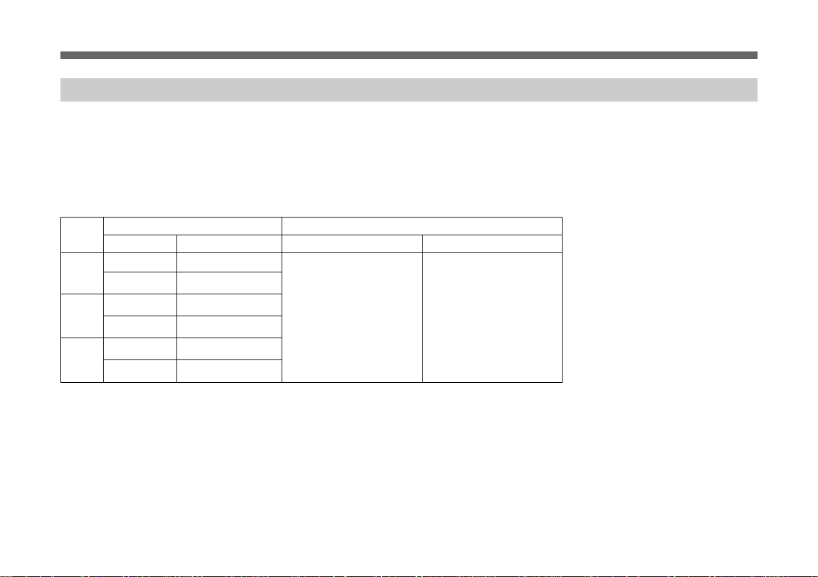
System Configuration
The WRT-808A can be used with the WRR-800A/801A
UHF synthesized Diversity Tuner and also can be used with
the WRR-820A/840A/850A/855A UHF Synthesized
Diversity Tuner.
Sony 800 MHz band system models
a)
a)
Model name
Tuner
WRR-800A
WRR-801A
WRR-802A
WRR-805A
WRR-810A
WRR-820A
WRR-840A
WRR-850A
WRR-855A
WRR-860A
MB-806A
WRT- Frequency band
808A TV channel Frequency (MHz)
U64 64 770.125 - 775.875
65 776.125 - 781.875
U66 66 782.125 - 787.875
67 788.125 - 793.875
U68 68 794.125 - 799.875
69 800.125 - 805.875
a) These models cover only 68 and 69 channels.
b) For these models, the AN-820A UHF antenna and the WD-820A UHF antenna divider are required.
US
6
Transmitter or microphone
WRT-805A
WRT-807A
WRT-808A
WRT-810A
WRT-820A
WRT-822A
WRT-830A
WRT-860A
WRT-867A
b)
b)
b)
a)
Page 7
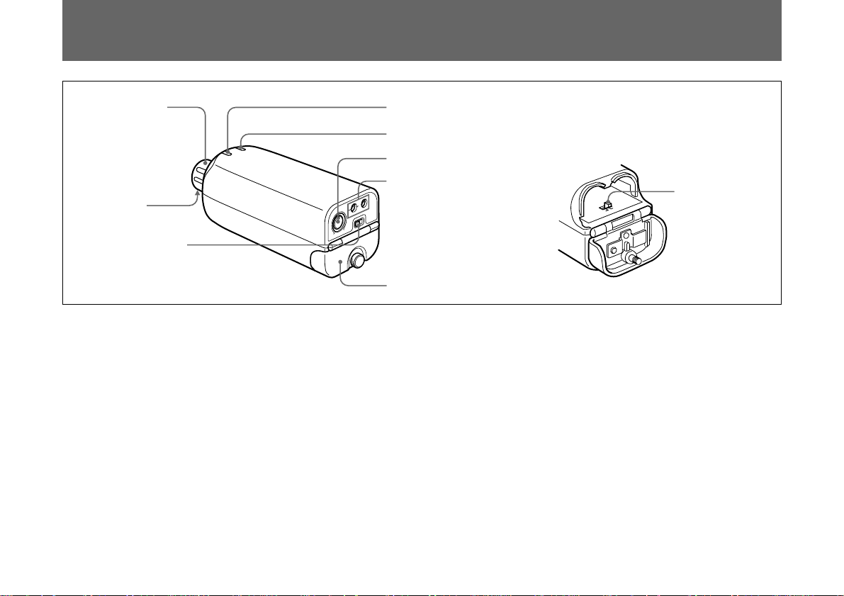
Parts Identification
1 Microphone
connector
Microphone
release button
(under side of
the unit)
2 POWER switch
1 Microphone connector
Connect to a dynamic microphone which has a XLR type
connector.
2 POWER switch
Turns the power of the transmitter ON or OFF.
3 POWER/BATT indicator
When turning on the unit, the POWER/BATT indicator
lights in green. While in operation, the LED indicates the
battery condition.
See “Power Supply” on page 8.
4 AF (audio frequency) /PEAK indicator
The AF/PEAK indicator lights in green when the supplied
3 POWER/BATT indicator
4 AF/PEAK indicator
5 Input LEVEL control
6 Channel select
switches
Battery compartment
audio frequency level is over the reference level. It lights in
red when the signal reaches the maximum level.
5 Input LEVEL control
Controls the input attenuation level.
“–60” position provides 0 dB attenuation, and “–10”
position provides 50 dB attenuation.
6 Channel select switches
Select the transmitting channel.
See “Channel Setting” on page 9.
7 RF power output switch
In normal use, set the switch to “50”.
See “Use of RF power output switch” on page 11.
7 RF power
output switch
US
7
Page 8
Power Supply
The transmitter can operate on two LR6 (size AA) alkaline
batteries continuously for about 4 hours at 25°C (77°F).
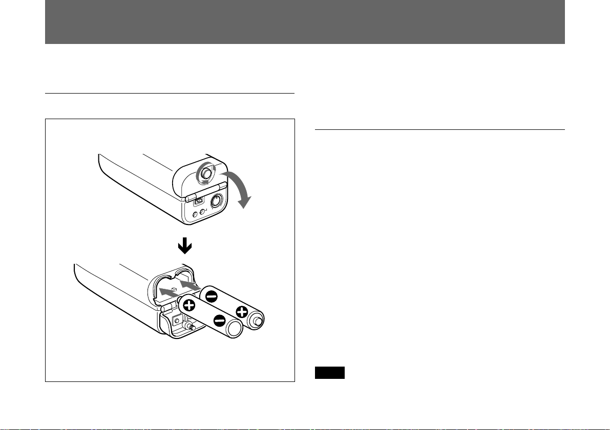
Installing the batteries
Two LR6 (size AA)
alkaline batteries
1 Turn the battery-compartment screw counterclockwise.
2 Match the polarities and insert the batteries.
3 Close the lid.
Battery indication
When you turn the power on, the POWER/BATT indicator
lights in green.
While in operation, the POWER/BATT indicator shows the
battery condition as shown below.
Lights in green: Good
Lights in red: The battery level is low. About one hour
is left for continuous operation.
Flashing in red: The batteries are almost exhausted.
The unit does not work.
Promptly replace the batteries when the POWER/BATT
indicator lights in red or flashes.
When the POWER/BATT indicator lights in red on this unit,
the BATT indication on the tuner (WRR-800A/801A/805A/
850A) starts flashing as a warning.
Note
The indication may be incorrect if the batteries are not new
when installed. If you plan to use the transmitter for a long
US
8
period, it is best to replace the batteries with new ones.
Page 9
Channel Setting
Notes on batteries
Use new alkaline batteries, and check the recommended
•
“
useby” date on the bottom of the batteries.
Do not pair different types of batteries.
•
Always replace the two batteries together.
•
The batteries are not rechargeable.
•
Be careful to install the batteries with the correct polarity.
•
When not using the transmitter for a l ong period, remove
•
the batteries to avoid leakage. If the batteries do leak, clean
all leakage from the unit. Leakage left in the unit may cause
poor battery contact. If there seems to be poor battery
contact, consult your Sony dealer.
Caution
Turn off the transmitter when setting the transmitting
channel to eliminate interference or noise on other wireless
equipment.
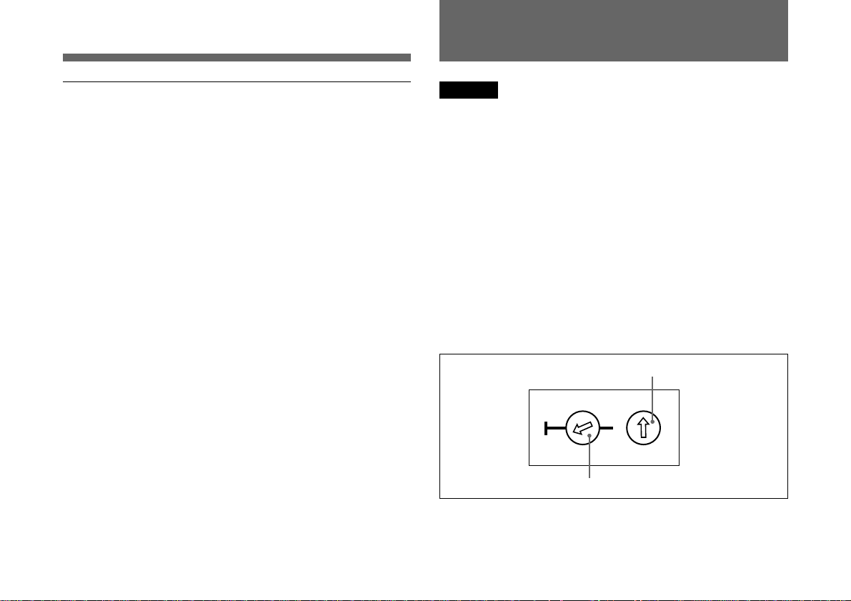
Each
“Wireless Channel”
digit TV channel number followed by another 2-digit
number, for example: 69-05.
Set the channel select switches for the clicked position of
the desired channel number by using a screw driver.
The left switch selects the TV band and the 10’s digit of the
transmitting channel. The right switch selects the 1’s digit of
the transmitting channel.
Example: when channel 69-05 is selected for U68 model
Set the left switch to “69” side “0”.
is represented on the unit by a 2-
Set the right switch to “5” .
68
69
0
0
113
2
3
2
5
4
4
6
37
2
149
0
8
For the selectable wireless channels and frequencies, see
“Wireless Channel Lists” on pages L-1 to L-3.
US
9
Page 10
Channel setting
Microphone System Operation
Notes
Be sure to set the arrow mark of the channel select switch
•
to the clicked position of the desired channel number. If
the switch does not click on the channel number, the
desired channel may not be set on the unit.
If the channel select switches are operated while the
•
transmitter is on, the POWER/BATT indicator flashes in
green as a warning.
If you set to any channel other than those listed in
•
“Wireless Channel Lists” on pages L-1 to L-3, the
POWER/BATT indicator flashes in green as a warning.
While the POWER/BATT indicator is flashing, the RF
•
output signal send from the transmitter becomes lower
than the usable level.
While POWER/BATT indicator on the transmitter is
flashing, the RF input indicator on the tuner may light, if
the transmitter locates near the tuner.
Though the RF input indicator lights on the tuner, the
Sony tuner (equipped with muting function) makes neither
noise nor audio output.
Make sure that the channel selected is the same as that
•
selected on the tuner used in the same system.
If there is a TV broadcasting station near by, do not use
•
the station's channel.
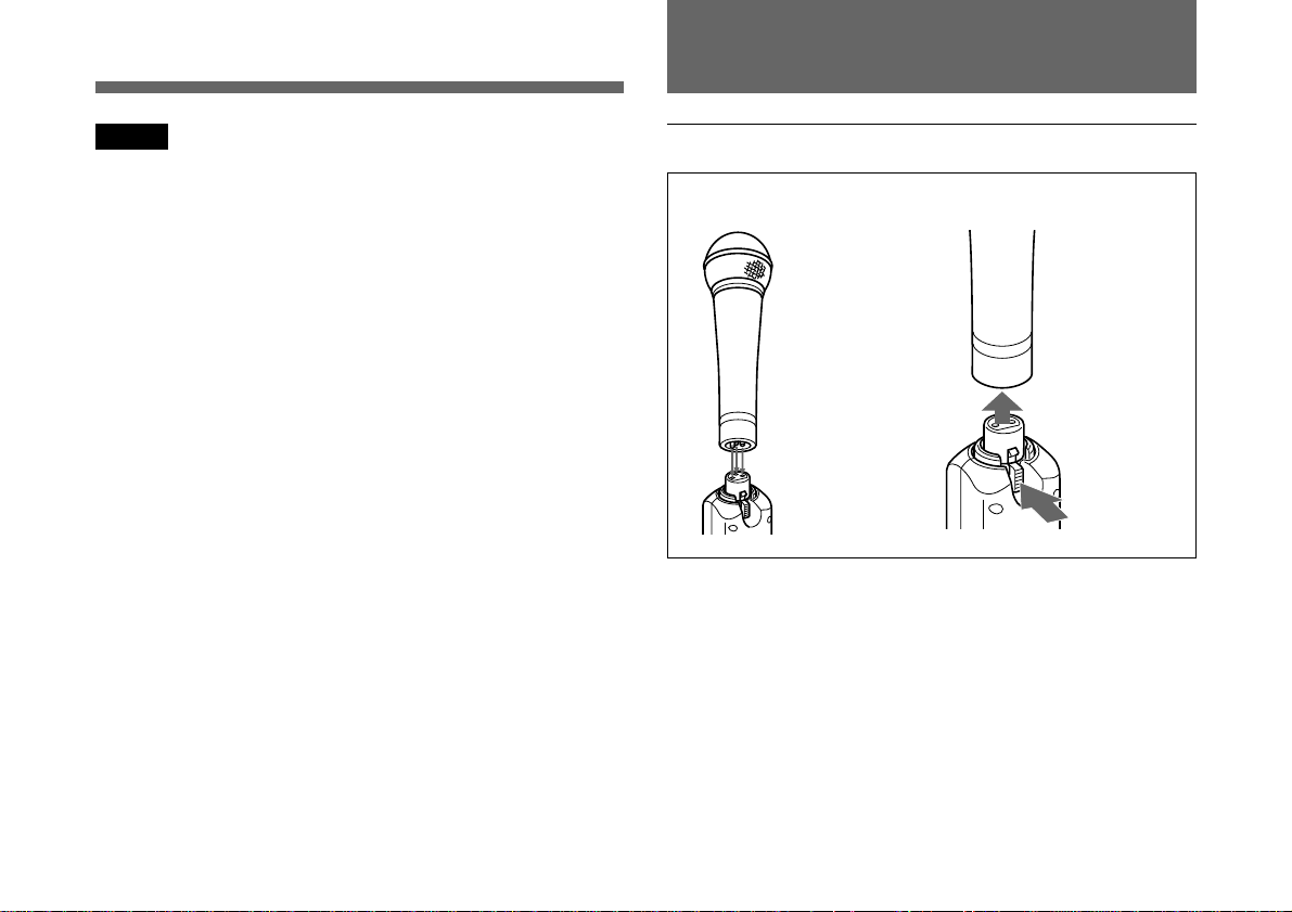
Microphone connection
Sony microphones F-780/740/730/720/710, etc.
Attach a microphone
to the unit directly or
use a microphone
cable with XLR-3-11
and XLR-3-12 type
connectors.
If noise is heard
Depending on the environment where the system is
installed, outside noise or radio wave may disrupt the
transmission of certain channels.
To select a channel under this circumstance, turn off the
transmitter. Select a channel on the tuner, at which the RF
indicator is off. (A channel free from noise or radio wave
interference is selected.) Then, set the same channel on the
transmitter.
To dettach a
microphone,
press the
microphone
release
button.
10
US
Page 11

Use of RF power output switch
The RF power output switch (located inside of the battery
compartment) selects the RF power output either 50 mW or
10 mW. In normal use, set the switch to “50” (factory preset
position).
50 mW output is suitable for optimum transmission over
long working distance.
10 mW output will be suitable for multi-channel operation
to eliminate the interference.
Use of input LEVEL control
When the AF/PEAK indicator lights in green continuously,
the supplied audio signal is continuously over the reference
level. If this occurs, use the input LEVEL control to avoid
sound distortion.
By turning the control to “–10”, the WRT-808A provides 50
dB input attenuation and can be inputted +4 dB (maximum
20 dB) line level signal.
Notes on microphone system operation
To operate with two or more channels, maintain a distance
•
of at least 30 cm (one ft.) between each pair of
transmitters.
For details of operation with two or more channels, refer
to the Operating Instructions for the WRR-800A/801A/
805A, etc.
Ensure that the transmitter set to channels not being used
•
are either turned off or set to the minimum output level.
When powering the transmitter on or off, to keep the noise
•
to a minimum, set the audio output level from the tuner or
mixer to a minimum.
Powering the transmitter on without checking the channel
•
selection first may interfere with the operation of other
microphones/transmitters, if the current setting is already
being used.
To prevent noise generation, keep the transmitters at least
•
3m (10 feet) away from the tuner antennas when the
system is operated using a group which allows selection of
up to 11 channels.
Do not grip the transmitter while using as it
•
will significantly degrade good
performance, causing dropouts, etc. Hold
the microphone itself as shown.
11
US
Page 12
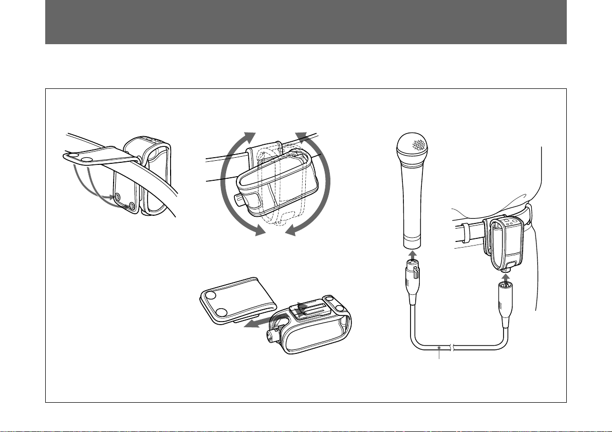
Use of the Soft Case
Using the soft case, you can attach the unit to a belt.
Attaching the unit to a belt Connecting the unit and your microphone
Turning the unit
Detaching the belt clip
1
2
Microphone cable with XLR-3-11 type
and XLR-3-12 type connectors
(available on the market)
12
While pressing down the shoe on the case 1,
pull out the belt clip 2.
US
Page 13

Specifications
Transmitter and modulation section
Oscillator Crystal controlled PLL synthesizer
Carrier frequencies
U64 model: 770.125 to 781.875 MHz
(94 settings at 125 kHz
intervals)
U66 model: 782.125 to 793.875 MHz
(94 settings at 125 kHz
intervals)
U68 model: 794.125 to 805.875 MHz
(94 settings at 125 kHz intervals)
RF power output 50 mW/10 mW selectable
Frequency stability Within ±0.005%
Tone signal 32.768 kHz
Type of emission 110KF3E
Type of antenna Internal, 1/4 - wave length wire
Pre-emphasis 50 µs
Deviation ±5 kHz (–60 dBV
with 0 dB audio attenuation)
Frequency response 70 to 15,000 Hz
Signal-to-noise ratio 57 dB or more
(A-weighted, with reference
deviation at WRR-800A/801A)
Audio attenuator 0 to 50 dB
Maximum input +26 dBV (1 kHz, with 50 dB audio
attenuation)
1)
, 1 kHz input,
Power section
Power requirements 3.0 V DC
(two LR6/size AA alkaline
batteries)
Battery life Approx. 4 hours at 25° C (77° F)
with Sony LR6 alkaline batteries
General
Operating temperature 0° C to +50° C (32° F to 122° F)
Storage temperature –30° C to +60° C (–22° F to +140° F)
Dimensions 40 × 108 × 40 mm (w/h/d)
(15/8 × 43/8 × 15/8 inches)
Mass Approx. 175 g (6 oz) including
batteries
Supplied accessories
Operating Instructions (1)
Soft Case (1)
Design and specifications are subject to change without
notice.
. . . . . . . . . . . . . . . . . . . . . . . . . . . . . . . . . . . . . . . . . . . . . . . . . . . . . . . . . . . . . . . . . . . . . . . . . . . . . . . . . . . . . . . . . . . . . . . . . . . . . . . . . . . . . . . . . . . . . . . . . . . . . . .
1) 0 dBV = 1 Vrms
13
US
Page 14

Français
Table des matières
Précautions
Précautions......................................................................... 2
Aperçu ................................................................................ 3
Canaux sans fil sélectionnables ..................................... 3
Caractéristiques.............................................................. 4
Configuration système ................................................... 5
Identification des composants .......................................... 6
Alimentation électrique..................................................... 7
Réglage des canaux............................................................ 8
Fonctionnement du système de microphone ................... 9
Utilisation de l’étui souple............................................... 11
Spécifications.................................................................... 12
Listes des canaux sans fil .............................................. L-1
• Cet appareil est conçu pour utilisation à une température
ambiante de 0 à 50 °C.
• Ne pas placer cet appareil sur ou près des sources de
chaleur comme l’équipement d’éclairage ou les
amplificateurs, ou dans un endroit exposé au soleil ou à
une humidité excessive, au risque d’endommager la
finition extérieure ou les composants internes de
l’appareil.
• Si l’appareil est utilisé dans des endroits très humides ou
poussiéreux, ou en présence d’un gaz actif, en nettoyer la
surface et les connecteurs avec un linge propre et doux
immédiatement après utilisation sans quoi sa durée utile
pourrait être écourtée.
• Ne jamais utiliser de dissolvant organique tel que du
diluant ou du benzène pour le nettoyage, au risque
d’endommager la finition de l’appareil.
• L’ajustement de cet appareil est très précis. Ne pas
modifier les composants internes ni essayer de les réparer.
FR
2
Page 15

Aperçu
Le WRT-808A est un transmetteur qui convertit un
microphone dynamique portable en microphone sans fil,
assurant ainsi une excellente qualité sonore du microphone
proprement dit tout en offrant la facilité requise pour les
applications de journalisme électronique (“ Electronic News
Gathering ”, ENG) et de production électronique sur site
(“ Electronic Field Production”, EFP). Utilisez ce
transmetteur hautement fiable en combinaison avec un
système de microphone UHF sans fil à bande de 800 MHz
Sony pour vos activités de télédiffusion et de production
cinématographique.
Canaux sans fil sélectionnables
Le transmetteur et le syntoniseur du système de microphone
sans fil sont classés par bande de fréquence.
Une bande de fréquence de 12 MHz (ou deux canaux de
télévision portant des numéros consécutifs, par exemple 68
et 69 sur le modèle WRT-808A/68) est assignée à chaque
modèle de transmetteur et de syntoniseur.
Lors de la configuration d’un système de microphone UHF
sans fil, veillez à combiner un transmetteur et un syntoniseur
ayant le même numéro de canal de télévision.
Modèle U68
Une bande de fréquence de 794 - 806 MHz est assignée au
modèle WRT-808A/68, qui lui permet de fonctionner sur
l’une des 94 fréquences porteuses du plan des canaux
original Sony par incréments de 125 kHz dans la bande des
canaux de télévision 68 et 69.
Pour connaître les canaux sélectionnables, voir “Listes des
canaux sans fil” à la page L-1.
Modèle U66
Une bande de fréquence de 782 -794 MHz est assignée au
modèle WRT-808A/66, qui lui permet de fonctionner sur
l’une des 94 fréquences porteuses du plan des canaux
original Sony par incréments de 125 kHz dans la bande des
canaux de télévision 66 et 67.
Pour connaître les canaux sélectionnables, voir “Listes des
canaux sans fil” à la page L-2.
Modèle U64
Une bande de fréquence de 770 - 782 MHz est assignée au
modèle WRT-808A/64, qui lui permet de fonctionner sur
l’une des 94 fréquences porteuses du plan des canaux
original Sony par incréments de 125 kHz dans la bande des
canaux de télévision 64 et 65.
FR
Français
Pour connaître les canaux sélectionnables, voir “Listes des
canaux sans fil” à la page L-3.
3
FR
Page 16

Caractéristiques
Sélection simple de 94 canaux
Le système synthétisé PLL assure une sélection simple de
94 canaux et une compatibilité totale avec le système de
microphone sans fil à 800 MHz Sony.
Connexion simple et fiable
Le WRT-808A peut être adapté à une large variété de
microphone filaires dotés d’un connecteur audio XLR. Cette
connexion fiable permet un fonctionnement exempt de
parasites.
Information sur le statut des piles sur le transmetteur et
le syntoniseur
Pour prévenir la défaillance des piles, le WRT-808A affiche
le statut des piles au moyen d’une indication par DEL verte,
rouge et clignotante. Environ une heure avant l’épuisement
des piles, le WRT-808A fournit des informations sur l’état
des piles pour activer l’alarme sur le syntoniseur WRR800A/801A/805A/850A.
Indication par DEL de l’entrée audio
L’indicateur AF/PEAK vous permet de contrôler d’un seul
coup d’œil la condition du niveau d’entrée audio.
Compact et léger
La technologie de montage à haute densité permet d’obtenir
un transmetteur compact et léger pour des reportages
nécessitant des moyens mobiles ( ENG (journalisme
électronique) et EFP (production électronique sur site)).
Fonctionnement au moyen de piles aisément disponibles
Vous disposez d’approximativement quatre heures
d’utilisation en continu avec deux piles alcalines AA (LR6).
Le convertisseur CC-CC assure une puissance de sortie des
piles uniforme durant toute leur durée de vie.
FR
4
Contrôle continu de l’atténuation d’entrée
Lorsqu’un signal audio d’une puissance excessive est entré,
le niveau d’entrée peut être réglé en continu dans la plage de
0 à 50 dB.
Si vous sélectionnez l’atténuation de 50 dB, le WRT-808A
peut accepter un niveau d’entrée de ligne de +4 dB
(maximum 20 dB).
Puissance de sortie RF sélectionnable
Vous pouvez sélectionner le niveau de sortie RF de 50 mW
ou 10 mW en fonction des conditions d’utilisation.
Page 17

Aperçu
Configuration système
Le WRT-808A peut également être utilisé avec les
syntoniseurs de déviation UHF synthétisés WRR-800A/
801A et WRR-820A/840A/850A/855A.
Modèles Sony à bande de 800 MHz
WRT- Bande de fréquence
808A Canaux de télévision Fréquence (MHz)
Transmetteur ou microphone
U64 64 770,125 - 775,875
65 776,125 - 781,875
U66 66 782,125 - 787,875
67 788,125 - 793,875
U68 68 794,125 - 799,875
69 800,125 - 805,875
a) Ces modèles couvrent uniquement les canaux 68 et 69.
b) Ces modèles requièrent une antenne UHF AN-820A et un diviseur
d’antenne UHF WD-820A UHF.
Désignation de modèle
WRT-805A
WRT-807A
WRT-808A
WRT-810A
WRT-820A
WRT-822A
WRT-830A
WRT-860A
WRT-867A
a)
a)
Syntoniseur
WRR-800A
WRR-801A
WRR-802A
WRR-805A
WRR-810A
WRR-820A
WRR-840A
WRR-850A
WRR-855A
WRR-860A
MB-806A
b)
b)
b)
a)
FR
5
Page 18

Identification des composants
1 Connecteur du
microphone
3 Indicateur POWER/BATT
4 Indicateur AF/PEAK
Bouton de
dégagement du
microphone
(partie inférieure
de l’appareil)
5 Commande de niveau d’entrée
6 Commutateur de
2 Commutateur
POWER
Compartiment à piles
1 Connecteur du microphone
Raccordez un microphone dynamique doté d’un connecteur
de type XLR.
2 Commutateur POWER
Met le transmetteur sous ou hors tension.
3 Indicateur POWER/BATT
Lors de la mise sous tension de l’appareil, l’indicateur
POWER/BATT s’allume en vert. En cours de
fonctionnement, la DEL indique l’état des piles.
Reportez-vous à “Alimentation électrique” à la page 8.
4 Indicateur AF (fréquence audio) /PEAK (crête)
L’indicateur AF/PEAK s’allume en vert lorsque le niveau de
la fréquence audio fourni dépasse le niveau de référence. Il
FR
6
sélection de canaux
7 Commutateur
de puissance
de sortie RF
s’allume en rouge lorsque le signal atteint le niveau
maximum.
5 Commande de niveau d’entrée (LEVEL)
Contrôle le niveau d’atténuation d’entrée.
La position “ –60 ” fournit une atténuation de 60 dB et la
position “ –10 ” une atténuation de 50 dB.
6 Commutateur de sélection de canaux
Sélectionne le canal de transmission.
Reportez-vous à “Réglage des canaux” à la page 9.
7 Commutateur de puissance de sortie RF
En utilisation normale, mettez le commutateur sur “50”.
Reportez-vous à “Utilisation du commutateur de puissance
de sortie RF” à la page 10.
Page 19

Alimentation électrique
Le transmetteur peut fonctionner avec deux piles alcalines
LR6 (AA) pendant environ 4 heures en continu à une
température ambiante de 25°C (77°F).
Mise en place des piles
Deux piles LR6 (AA)
alcaline
1 Tournez la vis du compartiment à piles dans le sens
antihoraire.
2 Introduisez les piles en veillant à faire coïncider les
polarités.
3 Refermez le couvercle.
Indication d’alimentation
Lors de la mise sous tension de l’appareil, l’indicateur
POWER/BATT s’allume en vert.
En cours de fonctionnement, l’indicateur POWER/BATT
indique l’état des piles comme illustré ci-dessous.
S’allume en vert: Piles pleines
S’allume en rouge: Les piles sont faibles. Il reste environ
une heure d’utilisation en continu.
Clignote en rouge: Les piles sont presque épuisées.
L’appareil ne fonctionne plus.
Remplacez les piles sans tarder lorsque l’indicateur
POWER/BATT s’allume en rouge ou clignote.
Lorsque l’indicateur POWER/BATT s’allume en rouge sur
cet appareil , l’indication BATT du syntoniseur (WRR800A/801A/805A/850A) commence à clignoter en guise
d’avertissement.
Remarque
Il se peut que l’indication soit incorrecte si les piles ne sont
pas neuves lorsqu’elles sont mises en place. Si vous
prévoyez d’utiliser le transmetteur un certain temps, il est
préférable de remplacer les piles par des neuves.
7
FR
Page 20

Réglage des canaux
Remarques sur les piles
• Utilisez des piles alcalines neuves et vérifiez la date
“d’utilisation” recommandée au bas des piles.
• Ne mélangez pas différents types de piles.
• Remplacez toujours les deux piles ensemble.
• Les piles ne sont pas rechargeables.
• Veillez à mettre en place les piles en respectant les
polarités correctes.
• Si vous prévoyez de ne pas utiliser le transmetteur pendant
une période prolongée, retirez-en les piles afin de prévenir
toute fuite des piles. Si les piles fuient, nettoyez le liquide
qui s’est écoulé dans l’appareil. La présence de liquide
dans l’appareil peut provoquer un mauvais contact des
piles. Si les piles présentent des mauvais contacts,
consultez votre revendeur Sony.
Attention
Désactivez le transmetteur lors du réglage du canal de
transmission afin d’éliminer toute interférence ou parasite
avec d’autres appareils sans fils.
Chaque “canal sans fil” est représenté sur l’appareil par un
numéro de canal télévisé à 2 chiffres suivi d’un autre
numéro à 2 chiffres, par exemple: 69-05.
Réglez les commutateurs de sélection de canal sur la
position encliquetable du numéro du canal désiré à l’aide
d’un tournevis. Le commutateur de gauche sélectionne la
bande TV et le chiffre des dizaines du canal de transmission.
Le commutateur de droite sélectionne le chiffre des unités
du canal de transmission.
Exemple: lorsque le canal 69-05 est sélectionné pour le
modèle U68
Mettez le commutateur droit sur “5” .
2
0
0
113
3
2
68
69
Mettez le commutateur gauche sur “69”, côté “0”.
5
4
4
6
37
2
149
0
8
Pour connaître les canaux sans fil et les fréquences,
reportez-vous aux “ Listes des canaux sans fil ” aux pages
FR
8
L-1 à L-3.
Page 21

Réglage des canaux
Fonctionnement du système de
microphone
Remarques
• Réglez le repère fléché du sélecteur de canal sur la
position encliquetable du numéro du canal désiré. Si le
commutateur ne s’encliquette pas sur le numéro du canal
désiré, c’est peut-être parce que ce canal n’est pas réglé
sur l’appareil.
• Si les commutateurs de sélection de canal sont actionnés
lorsqu’un transmetteur est sous tension, l’indicateur
POWER/BATT clignote en vert en guise d’avertissement.
• Si vous choisissez n’importe quel canal autre que ceux
repris dans les “ Listes des canaux sans fil” aux pages L-1
à L-3, l’indicateur POWER/BATT clignote en vert en
guise d’avertissement.
• Lorsque l’indicateur POWER/BATT clignote, le signal de
sortie RF envoyé par le transmetteur devient inférieur au
niveau utilisable.
Lorsque l’indicateur POWER/BATT du transmetteur
clignote, l’indicateur d’entrée RF du syntoniseur peut
s’allumer si le transmetteur se trouve à proximité du
syntoniseur.
Bien que l’indicateur d’entrée RF du syntoniseur s’allume,
le syntoniseur Sony (doté de la fonction de coupure) ne
produit ni parasites ni sortie audio.
• Assurez-vous que le canal sélectionné est le même que
celui sélectionné sur le syntoniseur utilisé dans le même
système.
• S’il y a une station de télévision émettrice à proximité,
n’utilisez pas le canal de cette station.
Connexion du microphone
Microphones Sony F-780/740/730/720/710, etc
Raccordez directement
un microphone à
l’appareil ou utilisez un
câble pour microphone
doté de connecteurs de
type XLR-3-11 et XLR3-12.
Pour débrancher
un microphone,
appuyez sur le
bouton de
dégagement du
microphone.
En présence de parasites
En fonction de l’environnement où le système est installé,
des parasites extérieurs ou des ondes radio peuvent nuire à
la transmission de certains canaux.
Pour sélectionner un canal dans ces circonstances, mettez le
transmetteur hors tension. Sélectionnez sur le syntoniseur
un canal pour lequel l’indicateur RF est éteint. (Un canal
exempt de parasites ou d’interférences radio ondulatoires est
sélectionné.) Réglez ensuite le même canal sur le
transmetteur.
FR
9
Page 22

Utilisation du commutateur de puissance de sortie
RF
Le commutateur de puissance de sortie RF (situé à
l’intérieur du compartiment à piles) sélectionne la puissance
de sortie RF de 50 mW ou 10 mW. En utilisation normale,
mettez le commutateur sur “50” (position de présélection
d’usine).
Une puissance de sortie de 50 mW convient à une
transmission optimale sur de longues distances de travail.
Une tension de sortie de 10 mW convient à un
fonctionnement multicanal pour supprimer les interférences.
Utilisation du contrôle de niveau d’entrée
Si l’indicateur AF/PEAK s’allume en vert en continu, cela
signifie que le signal audio fourni est continuellement audessus du niveau de référence. Si ce cas se produit, utilisez
le contrôle de niveau d’entrée pour éviter toute distorsion du
son.
En réglant la commande sur “–10”, le WRT-808A assure
une atténuation d’entrée de 50 dB et un signal d’un niveau
d’entrée de +4 dB (maximum 20 dB) peut être entré.
FR
10
Remarques sur le fonctionnement du système de
microphone
• Pour fonctionner avec deux ou plusieurs canaux,
maintenir une distance d’au moins 30 cm entre chaque
paire de transmetteurs.
Pour plus de détails sur le fonctionnement avec deux
canaux ou plus, reportez-vous au mode d’emploi du WRR800A/801A/805A.
• Assurez-vous que les syntoniseurs réglés sur des canaux
non utilisés sont soit hors fonction, soit réglés sur la
puissance de sortie minimale.
• Lors de la mise sous et hors tension du transmetteur, et
afin de réduire les parasites au minimum, réglez le niveau
de sortie audio du syntoniseur ou du mixeur au minimum.
• La mise sous tension du transmetteur sans vérifier d’abord
la sélection du canal risque de nuire au fonctionnement
des autres microphones/transmetteurs, si le réglage du
courant est déjà utilisé.
• Pour prévenir la génération de parasites, gardez les
transmetteurs à au moins 3 m (10 pieds) des
antennes du syntoniseur lorsque le système est
exploité avec un groupe offrant une sélection
de 11 canaux maximum.
• Ne saisissez pas le transmetteur en cours
d’utilisation car cela réduira
considérablement les performances en
provoquant des pertes de signal, etc.
Saisissez le microphone proprement dit
comme illustré.
Page 23

Utilisation de l’étui souple
Lorsque vous utilisez un étui souple, vous pouvez porter le
système à la ceinture.
Fixation de l’appareil à la
ceinture
Pivotement du système
Retrait du circlips de ceinture
1
2
Tout en maintenant le sabot
de l’étui 1 enfoncé, retirez
le circlips de ceinture 2.
Raccordement de l’appareil
et de votre microphone
Câble pour microphone doté de
connecteurs de type XLR-3-11 et
XLR-3-12 (disponible dans le
commerce)
11
FR
Page 24

Spécifications
Transmetteur et modulation
Oscillateur Synthétiseur PLL piloté par cristal
Fréquences de réception
Version U64: 770,125 - 781,875 MHz
(94 réglages à intervalles de 125 kHz )
Version U66: 782,125 - 793,875 MHz
(94 réglages à intervalles de 125 kHz )
Version U68: 794,125 - 805,875 MHz
(94 réglages à intervalles de 125 kHz )
Puissance de sortie RF Commutable, 50 mW/10 mW
Stabilité de fréquence Dans une plage de ± 0,005%
Signal de tonalité 32,768 kHz
Type de transmission 110KF3E
Type d’antenne Interne, 1/4 - longueur d’onde,
filaire
Préaccentuation 50 µs
Déviation ± 5 kHz (–60 dBV 1), entrée 1 kHz,
avec atténuation audio de 0 dB)
Réponse en fréquence 70 à 15.000 Hz
Rapport signal/bruit 57 dB ou plus
(pondération A, avec déviation de
référence WRR-800A/801A)
Atténuateur audio 0 à 50 dB
Entrée maximum +26 dBV (1 kHz, avec atténuation
audio de 50 dB)
Alimentation
Puissance de raccordement
3V CC (deux piles alcalines LR6
(AA))
Autonomie des piles Approx. 4 heures avec deux piles
alcalines Sony LR6 à 25 °C (77°F)
Généralités
Température de service
Température de stockage
Dimensions 40 × 108 × 40 mm (l/h/p)
Masse 175 g (6 oz), piles comprises
Accessoires fournis
Mode d’emploi (1)
Etui souple (1)
Conception et spécifications modifiables sans préavis.
0 à +50 °C (32 à 122 °F)
–30 à +60 °C (–22 à +140 °F)
(15/8 × 43/8 × 15/8 pouces)
. . . . . . . . . . . . . . . . . . . . . . . . . . . . . . . . . . . . . . . . . . . . . . . . . . . . . . . . . . . . . . . . . . . . . . . . . . . . . . . . . . . . . . . . . . . . . . . . . . . . . . . . . . . . . . . . . . . . . . . . . . . . . . .
1) 0 dBV= 1Vrms
FR
12
Page 25

Español
Índice
Precauciones
Precauciones....................................................................... 3
Descripción general ........................................................... 4
Canales inalámbricos seleccionables ............................. 4
Características ................................................................ 5
Configuración del sistema ............................................. 6
Identificación de componentes ......................................... 7
Fuente de alimentación ..................................................... 8
Ajuste de canales................................................................ 9
Empleo del sistema de micrófono................................... 10
Empleo del estuche blando ............................................. 12
Especificaciones ............................................................... 13
Listas de canales inalámbricos ..................................... L-1
• La unidad ha sido diseñada para emplearse a una
temperatura ambiente de 0°C a 50°C (32°F a 122°F).
• No coloque la unidad en o cerca de fuentes de calor, como
lámparas o amplificadores de potencia, o en lugares
expuestos a la luz solar directa o la humedad excesiva. En
estos lugares, el acabado o los componentes internos de la
unidad se pueden dañar.
• Si la unidad se utiliza en lugares muy húmedos, con
mucho polvo o expuestos al gas, limpie bien su superficie
y los conectores con un paño suave y seco poco después
de cada uso.
Un uso prolongado de la unidad en dichas condiciones, o
sin limpiarla después de utilizarla en tales situaciones,
puede acortar su vida útil.
• Para limpiar la unidad, nunca utilice solventes orgánicos
como diluyentes o bencina, ya que pueden dañar el
acabado.
• La unidad ha sido ajustada con precisión en fábrica. No
debe tocar o tratar de reparar sus componentes internos.
ES
Español
ES
3
Page 26

Descripción general
El WRT-808A es un transmisor que convierte un micrófono
dinámico de mano en inalámbrico, garantizando una
excelente calidad de sonido del propio micrófono y
proporcionando prácticas aplicaciones, especialmente
Electronic News Gathering (ENG), en directo y otras
aplicaciones Electronic Field Production (EFP). En
combinación con el sistema de micrófono inalámbrico de
UHF de Sony con banda de 800 MHz, emplee este
transmisor de alta fiabilidad para fines de emisión y
producción de películas.
Canales inalámbricos seleccionables
El transmisor y sintonizador del sistema de micrófono
inalámbrico se clasifican por la banda de frecuencias.
Una banda de frecuencias de 12-MHz (o dos canales de TV
de número consecutivo, como el 68 y el 69 del modelo
WRT-808A/68) está asignada a cada modelo de transmisor
y sintonizador.
Para componer un sistema de micrófono inalámbrico de
UHF, cerciórese de combinar un transmisor y un
sintonizador que posean el mismo número de canal de TV.
Modelo U68
Se asigna una banda de frecuencias de 794 - 806 MHz al
modelo WRT-808A/68, lo cual le permite funcionar con
cualquiera de las 94 frecuencias portadoras en incrementos
de 125-kHz del plan original de canales de Sony en el
intervalo de canales de TV 68 y 69.
Para los canales seleccionables, consulte “Listas de canales
inalámbricos” en la página L-1.
Modelo U66
Se asigna una banda de frecuencias de 782 -794 MHz al
modelo WRT-808A/66, lo cual le permite funcionar con
cualquiera de las 94 frecuencias portadoras en incrementos
de 125 kHz del plan original de canales de Sony en el
intervalo de canales de TV 66 y 67.
Para los canales seleccionables, consulte “Listas de canales
inalámbricos” en la página L-2.
Modelo U64
Se asigna una banda de frecuencias de 770 -782 MHz al
modelo WRT-808A/64, lo cual le permite funcionar con
cualquiera de las 94 frecuencias portadoras en incrementos
de 125 kHz del plan original de canales de Sony en el rango
de canales de TV 64 y 65.
Para los canales seleccionables, consulte “Listas de canales
inalámbricos” en la página L-3.
ES
4
Page 27

Características
Fácil selección de 94 canales
El sistema PLL sintetizado permite seleccionar fácilmente
94 canales y ofrece una total compatibilidad con el sistema
de micrófono inalámbrico de la serie 800 MHz de Sony.
Conexión fácil y fiable
La unidad WRT-808A puede adaptarse a una amplia gama
de micrófonos con cable que dispongan de conector de
audio XLR. Gracias a la fiable conexión, se garantiza un
funcionamiento sin ruidos.
Compacto y ligero
La tecnología de montaje de alta densidad ha hecho posible
la creación de este transmisor compacto y ligero, que le
permite desplazarse a cualquier parte para realizar la
recopilación electrónica de noticias (ENG: Electronic News
Gathering) y la producción electrónica de campo (EFP:
Electronic Field Production).
Alimentación con pilas de fácil disponibilidad
Mediante el empleo de dos pilas alcalinas tamaño AA
(LR6), es posible emplear la unidad de forma continua
durante aproximadamente cuatro horas. Gracias al
convertidor de CC-CC, se garantiza un suministro
permanente de alimentación aunque se agoten las pilas.
Información del estado de las pilas del transmisor y del
sintonizador
Para evitar fallos de funcionamiento de las pilas, la unidad
WRT-808A muestra el estado de las pilas mediante la
iluminación de la indicación LED en verde, en rojo y
parpadeante. Aproximadamente una hora antes de que se
agoten las pilas, la WRT-808A proporciona información
sobre éstas para activar la alarma del sintonizador WRR800A/801A/805A/850A.
Indicación LED de entrada de audio
El indicador AF/PEAK permite obtener información sobre
la condición del nivel de entrada de audio con un sólo
vistazo.
Control continuo de atenuación de entrada
Si se introduce una señal de audio excesivamente intensa, el
nivel de entrada podrá ajustarse dentro del margen de 0 a 50
dB de forma continua.
El ajuste de atenuación de 50 dB permite que la unidad
WRT-808A pueda aceptar una entrada de nivel de línea de
+4 dB (máximo de 20 dB).
Salida de potencia de RF seleccionable
Es posible seleccionar el nivel de salida de RF (entre 50 mW
o 10 mW) que mejor se adapte a la condición de empleo.
ES
5
Page 28

Descripción general
Configuración del sistema
La unidad WRT-808A puede utilizarse con el sintonizador
de diversidad de UHF sintetizado WRR-800A/801A e,
igualmente, puede emplearse con el sintonizador WRR820A/840A/850A/855A.
Modelos Sony de sistemas de banda de 800 MHz
WRT- Bande de fréquence
808A Canal de TV Frecuencia (MHz)
U64 64 770,125 - 775,875
65 776,125 - 781,875
U66 66 782,125 - 787,875
67 788,125 - 793,875
U68 68 794,125 - 799,875
69 800,125 - 805,875
a) Estos modelos sólo incluyen los canales 68 y 69.
b) Para estos modelos se requiere el uso de la antena de UHF AN-820A y
del divisor de antena de UHF WD-820A.
Transmisor o micrófono
WRT-805A
WRT-807A
WRT-808A
WRT-810A
WRT-820A
WRT-822A
WRT-830A
WRT-860A
WRT-867A
a)
a)
Modelo
Sintonizador
WRR-800A
WRR-801A
WRR-802A
WRR-805A
WRR-810A
WRR-820A
WRR-840A
WRR-850A
WRR-855A
WRR-860A
MB-806A
b)
b)
b)
a)
ES
6
Page 29

Identificación de componentes
1 Conector de
micrófono
Tecla de extracción
del micrófono (bajo
lateral de la unidad)
2 Interruptor POWER
1 Conector de micrófono
Conéctelo a un micrófono dinámico que disponga de un
conector tipo XLR.
2 Interruptor POWER
Permite conectar y desconectar la alimentación del
transmisor.
3 Indicador POWER/BATT
Al encender la unidad, la luz verde del indicador POWER/
BATT se ilumina. Mientras está en funcionamiento, el
indicador luminoso avisa del estado de las pilas.
Consulte “Fuente de alimentación” en la página 8.
4 Indicador AF (frecuencia de audio) /PEAK
El indicador AF/PEAK se ilumina en verde cuando el nivel
3 Indicador POWER/BATT
4 Indicador AF/PEAK
5 Control Input LEVEL (nivel de
entrada)
6 Selectores de canal
Compartimiento de las pilas
de la frecuencia de audio suministrada supera el nivel de
referencia. Si la señal alcanza el nivel máximo, se ilumina
en rojo.
5 Control input LEVEL (nivel de entrada)
Controla el nivel de atenuación de entrada.
La posición “–60” proporciona una atenuación de 0 dB y la
posición “–10” proporciona una atenuación de 50 dB.
6 Selectores de canal
Permiten seleccionar el canal de transmisión.
Consulte “Ajuste de canales” en la página 9.
7 Interruptor de salida de potencia RF
Para el uso normal, ponga este interruptor en “50”.
Consulte “Uso del interruptor de salida de potencia RF”
en la página 11.
7 Interruptor de
salida de
potencia RF
ES
7
Page 30

Fuente de alimentación
El transmisor puede funcionar con dos pilas alcalinas tipo
LR6 (tamaño AA) de forma continua durante
aproximadamente 4 horas a 25°C (77°F).
Instalación de las pilas
Dos pilas alcalinas
tipo LR6 (tamaño
AA)
1 Gire el tornillo del compartimiento de las pilas en el
sentido contrario a las agujas del reloj.
2 Haga coincidir las polaridades e inserte las pilas.
ES
8
3 Cierre la tapa.
Indicación de las pilas
Al encender la unidad, el indicador POWER/BATT se
ilumina en verde.
Mientras la unidad está en funcionamiento, el indicador
POWER/BATT muestra el estado de las pilas, tal como se
muestra a continuación.
Luz verde: pila en buen estado
Luz roja: pila con poca carga. Con carga para
aproximadamente una hora de funcionamiento
continuo.
Luz roja parpadeante: las pilas están prácticamente
agotadas. La unidad no funciona.
Cambie inmediatamente las pilas cuando la luz del indicador
POWER/BATT sea roja o parpadee.
Cuando la luz roja del indicador POWER/BATT de esta
unidad se ilumina, la indicación BATT del sintonizador
(WRR-800A/801A/805A/850A) empieza a parpadear para
alertarle.
Nota
La indicación puede ser incorrecta si las pilas no son nuevas
cuando se instalan. Si tiene previsto utilizar el transmisor
durante un periodo prolongado, es preferible sustituir las
pilas por otras nuevas.
Page 31

Ajuste de canales
Notas sobre las pilas
• Utilice pilas alcalinas nuevas y compruebe la fecha de
“caducidad” recomendada en la parte inferior de éstas.
• No combine diferentes tipos de pilas.
• Sustituya siempre ambas pilas a la vez.
• Las pilas no son recargables.
• Tenga cuidado para instalar las pilas con la polaridad
correcta.
• Si no va a utilizar el transmisor durante mucho tiempo,
extraiga las pilas para evitar fugas. Si se producen fugas,
limpie bien la unidad. Si no se limpia correctamente
después de una fuga, puede producirse un contacto
defectuoso. Si sospecha que hay un contacto defectuoso,
consulte a su distribuidor Sony.
Precaución
Apague el transmisor para ajustar el canal de transmisión a
fin de eliminar las interferencias o ruidos en otros equipos
inalámbricos.
Cada “canal inalámbrico” está representado en la unidad
mediante un número de canal de TV de 2 dígitos, seguido de
otro número de 2 dígitos; por ejemplo: 69-05.
Emplee un destornillador para situar los selectores de canal
de la posición en la que haya hecho clic del número de canal
deseado. El selector izquierdo permite seleccionar la banda
de TV y los dígitos correspondientes a las decenas del canal
de transmisión. El selector derecho permite seleccionar el
dígito de unidades del canal de transmisión.
Ejemplo: si selecciona el canal 69-05 para el modelo U68
Ponga el selector derecho en “5” .
2
0
0
113
3
2
68
69
Ponga el selector izquierdo en “69” junto a “0”.
5
4
4
6
37
2
149
0
8
Para los canales inalámbricos y frecuencias que pueden
seleccionarse, consulte “Listas de canales inalámbricos” en
las páginas L-1 a L-3.
9
ES
Page 32

Ajuste de canales
Empleo del sistema de
micrófono
Notas
• Asegúrese de ajustar la marca de flecha del selector de
canales en la posición en la que haya hecho clic del
número de canal deseado. Si el selector no se ajusta
haciendo clic en el número de canal, es posible que el
canal deseado no se ajuste en la unidad.
• Si utiliza los selectores de canales mientras el transmisor
está encendido, la luz verde del indicador POWER/BATT
parpadea para alertarle.
• Si realiza el ajuste en un canal que no está incluido en las
“Listas de canales inalámbricos” de las páginas L-1 a L-3,
la luz verde del indicador POWER/BATT parpadea para
alertarle.
• Mientras el indicador POWER/BATT parpadee, el nivel
de la señal de salida RF enviada desde el transmisor será
inferior al utilizable.
Mientras el indicador POWER/BATT del transmisor
parpadee, es posible que el indicador de entrada RF del
sintonizador se ilumine, si dicho transmisor se encuentra
cerca del sintonizador.
Aunque el indicador de entrada RF se ilumine en el
sintonizador, el sintonizador Sony (equipado con función
de silenciamiento) no producirá ruido ni emitirá sonido.
• Asegúrese de que el canal seleccionado sea el mismo que
se haya seleccionado en el sintonizador utilizado en el
mismo sistema.
• Si hay una emisora de TV cerca, no utilice el canal de la
emisora.
Conexión del micrófono
Micrófonos Sony F-780/740/730/720/710, etc.
Conecte un micrófono
a la unidad
directamente o emplee
un cable de micrófono
con conectores de tipo
XLR-3-11 y XLR-3-12.
Para extraer
el micrófono,
pulse la tecla
de
extracción del
micrófono.
Si se escucha ruido
Dependiendo del entorno en el que instale el sistema, es
posible que el ruido exterior o las ondas de radio interfieran
en la transmisión de determinados canales.
Para seleccionar algún canal bajo esta circunstancia, apague
el transmisor. Seleccione el canal en el sintonizador, en el
que el indicador de RF esté desactivado. (Se selecciona un
canal sin ruidos o sin interferencias por ondas de radio.) A
continuación, ajuste el mismo canal en el transmisor.
10
ES
Page 33

Uso del interruptor de salida de potencia RF
El interruptor de salida de potencia RF (situado en el interior
del compartimiento de las pilas) permite seleccionar una
potencia de salida de RF de 50 mW o 10 mW. Para su uso
normal, ponga el interruptor en “50” (posición programada
en fábrica).
La salida de 50 mW resulta adecuada para obtener
transmisiones óptimas con largas distancias.
La salida de 10 mW resulta adecuada cuando se empleen
varios canales con el fin de eliminar las interferencias.
Uso del control input LEVEL (nivel de entrada)
Si el indicador AF/PEAK permanece iluminado en verde,
significa que la señal de audio suministrada se encuentra por
encima del nivel de referencia de forma continua. Si esto
ocurre, utilice el control input LEVEL para evitar que el
sonido se distorsione.
Al girar el control hasta “–10”, la unidad WRT-808A
proporcionará una atenuación de entrada de 50 dB y será
posible introducir una señal de nivel de línea de +4 dB
(máximo de 20 dB).
Notas sobre el funcionamiento del sistema de
micrófono
• Para operar con dos o más canales, mantenga una
distancia mínima de 30 cm (un pie) entre cada par de
transmisores.
Para obtener información detallada sobre el empleo con
dos canales o más, consulte el manual de instrucciones de
la unidad WRR-800A/801A/805A.
• Cerciórese de que los sintonizadores ajustados en canales
que no están en uso se encuentren apagados o tengan
activado el nivel mínimo de salida.
• Al conectar o desconectar la alimentación del transmisor,
para mantener un nivel mínimo de ruido, ajuste el nivel de
salida de audio del sintonizador o mezclador al mínimo.
• Activar la alimentación del transmisor sin comprobar
primero la selección de canales puede producir
interferencias con la operación de otros micrófonos/
transmisores si la selección actual ya se está utilizando.
• Para evitar que se produzca ruido, mantenga los
transmisores a una distancia de al menos 3m (10
pies) de las antenas del sintonizador cuando
emplee el sistema con un grupo que permita
seleccionar hasta 11 canales.
• No sujete el transmisor mientras está en
uso, ya que esto puede afectar de forma
negativa a su rendimiento, provocando
pérdidas, etc. Agarre el propio micrófono
como se muestra.
11
ES
Page 34

Empleo del estuche blando
Si utiliza el estuche blando, podrá fijar la unidad a un
cinturón.
Fijación de la unidad a un cinturón Giro de la unidad
Extracción del clip de cinturón
2
Mientras presiona la zapata hacia
abajo en el estuche 1, tire del clip
de cinturón 2.
ES
12
Conexión de la unidad y el micrófono
1
Cable de micrófono con conectores de
tipo XLR-3-11 y XLR-3-12 (disponible en
el mercado)
Page 35

Especificaciones
Sección del transmisor y modulación
Oscilador Sintetizador de PLL controlado por cristal
Frecuencias portadoras
Modelo U64: 770,125 a 781,875 MHz
(94 ajustes a intervalos de 125 kHz)
Modelo U66: 782,125 a 793,875 MHz
(94 ajustes a intervalos de 125 kHz)
Modelo U68: 794,125 a 805,875 MHz
(94 ajustes a intervalos de 125 kHz)
Salida de potencia RF
50 mW/10 mW seleccionable
Estabilidad de frecuencia
Dentro de ±0,005%
Señal de tono 32,768 kHz
Tipo de emisión 110KF3E
Tipo de antena Interna, cable de 1/4 de longitud de onda
Preacentuación 50 µs
Desviación ±5 kHz (–60 dBV
con atenuación de audio de 0 dB)
Respuesta de frecuencia
70 a 15.000 Hz
Relación señal/ruido
57 dB o superior (ponderación A, con
desviación de referencia en WRR-800A/
801A)
Atenuador de audio
0 a 50 dB
1)
, entrada de 1 kHz,
Entrada máxima
+26 dBV (1 kHz, con atenuación de audio
de 50 dB)
Sección de alimentación
Requisitos de alimentación
3,0 V CC (dos pilas alcalinas de tipo LR6/
tamaño AA)
Duración de las pilas
Aprox. 4 horas a 25°C (77°F)
con pilas alcalinas Sony LR6
Generales
Temperatura de funcionamiento
0°C a +50°C (32°F a 122°F)
Temperatura de almacenamiento
–30°C a +60°C (–22°F a +140°F)
Dimensiones 40 × 108 × 40 mm (an/al/prf)
(15/8 × 43/8 × 15/8 pulg.)
Masa Aprox. 175 g (6 oz) incluidas las pilas
Accesorios suministrados
Manual de instrucciones (1)
Estuche blando (1)
El diseño y las especificaciones están sujetos a cambios sin
previo aviso.
. . . . . . . . . . . . . . . . . . . . . . . . . . . . . . . . . . . . . . . . . . . . . . . . . . . . . . . . . . . . . . . . . . . . . . . . . . . . . . . . . . . . . . . . . . . . . . . . . . . . . . . . . . . . . . . . . . . . . . . . . . . . . . .
1) 0 dBV= 1Vrms
13
ES
Page 36

14
ES
Page 37

Wireless Channel Lists / Listes des canaux sans fil /
Listas de canales inalámbricos
For 68-Version Model Using TV Channels 68 and 69 /
Pour le modèle 68 utilisant les canaux de télévision 68 et 69 /
Para modelos de la versión 68 que utilizan los canales de TV 68 y 69
Channel Frequency(MHz) Channel Frequency(MHz) Channel Frequency(MHz) Channel Frequency(MHz)
Canal Fréquence Canal Fréquence Canal Fréquence Canal Fréquence
Frecuencia Frecuencia Frecuencia Frecuencia
68-01 794.125 68-25 797.125 69-01 800.125 69-25 803.125
68-02 794.250 68-26 797.250 69-02 800.250 69-26 803.250
68-03 794.375 68-27 797.375 69-03 800.375 69-27 803.375
68-04 794.500 68-28 797.500 69-04 800.500 69-28 803.500
68-05 794.625 68-29 797.625 69-05 800.625 69-29 803.625
68-06 794.750 68-30 797.750 69-06 800.750 69-30 803.750
68-07 794.875 68-31 797.875 69-07 800.875 69-31 803.875
68-08 795.000 68-32 798.000 69-08 801.000 69-32 804.000
68-09 795.125 68-33 798.125 69-09 801.125 69-33 804.125
68-10 795.250 68-34 798.250 69-10 801.250 69-34 804.250
68-11 795.375 68-35 798.375 69-11 801.375 69-35 804.375
68-12 795.500 68-36 798.500 69-12 801.500 69-36 804.500
68-13 795.625 68-37 798.625 69-13 801.625 69-37 804.625
68-14 795.750 68-38 798.750 69-14 801.750 69-38 804.750
68-15 795.875 68-39 798.875 69-15 801.875 69-39 804.875
68-16 796.000 68-40 799.000 69-16 802.000 69-40 805.000
68-17 796.125 68-41 799.125 69-17 802.125 69-41 805.125
68-18 796.250 68-42 799.250 69-18 802.250 69-42 805.250
68-19 796.375 68-43 799.375 69-19 802.375 69-43 805.375
68-20 796.500 68-44 799.500 69-20 802.500 69-44 805.500
68-21 796.625 68-45 799.625 69-21 802.625 69-45 805.625
68-22 796.750 68-46 799.750 69-22 802.750 69-46 805.750
68-23 796.875 68-47 799.875 69-23 802.875 69-47 805.875
68-24 797.000 69-24 803.000
L
Channel lists / Listes des canaux sans fil /
Listas de canales inalámbricos
L-1
Page 38

Wireless Channel Lists / Listes des canaux sans fil / Listas de canales inalámbricos
For 66-Version Model Using TV Channels 66 and 67 /
Pour le modèle 66 utilisant les canaux de télévision 66 et 67 /
Para modelos de la versión 66 que utilizan los canales de TV 66 y 67
Channel Frequency(MHz) Channel Frequency(MHz) Channel Frequency(MHz) Channel Frequency(MHz)
Canal Fréquence Canal Fréquence Canal Fréquence Canal Fréquence
66-01 782.125 66-25 785.125 67-01 788.125 67-25 791.125
66-02 782.250 66-26 785.250 67-02 788.250 67-26 791.250
66-03 782.375 66-27 785.375 67-03 788.375 67-27 791.375
66-04 782.500 66-28 785.500 67-04 788.500 67-28 791.500
66-05 782.625 66-29 785.625 67-05 788.625 67-29 791.625
66-06 782.750 66-30 785.750 67-06 788.750 67-30 791.750
66-07 782.875 66-31 785.875 67-07 788.875 67-31 791.875
66-08 783.000 66-32 786.000 67-08 789.000 67-32 792.000
66-09 783.125 66-33 786.125 67-09 789.125 67-33 792.125
66-10 783.250 66-34 786.250 67-10 789.250 67-34 792.250
66-11 783.375 66-35 786.375 67-11 789.375 67-35 792.375
66-12 783.500 66-36 786.500 67-12 789.500 67-36 792.500
66-13 783.625 66-37 786.625 67-13 789.625 67-37 792.625
66-14 783.750 66-38 786.750 67-14 789.750 67-38 792.750
66-15 783.875 66-39 786.875 67-15 789.875 67-39 792.875
66-16 784.000 66-40 787.000 67-16 790.000 67-40 793.000
66-17 784.125 66-41 787.125 67-17 790.125 67-41 793.125
66-18 784.250 66-42 787.250 67-18 790.250 67-42 793.250
66-19 784.375 66-43 787.375 67-19 790.375 67-43 793.375
66-20 784.500 66-44 787.500 67-20 790.500 67-44 793.500
66-21 784.625 66-45 787.625 67-21 790.625 67-45 793.625
66-22 784.750 66-46 787.750 67-22 790.750 67-46 793.750
66-23 784.875 66-47 787.875 67-23 790.875 67-47 793.875
66-24 785.000 67-24 791.000
Frecuencia Frecuencia Frecuencia Frecuencia
L-2
Page 39

For 64-Version Model Using TV Channels 64 and 65 /
Pour le modèle 64 utilisant les canaux de télévision 64 et 65 /
Para modelos de la versión 64 que utilizan los canales de TV 64 y 65
Channel Frequency(MHz) Channel Frequency(MHz) Channel Frequency(MHz) Channel Frequency(MHz)
Canal Fréquence Canal Fréquence Canal Fréquence Canal Fréquence
64-01 770.125 64-25 773.125 65-01 776.125 65-25 779.125
64-02 770.250 64-26 773.250 65-02 776.250 65-26 779.250
64-03 770.375 64-27 773.375 65-03 776.375 65-27 779.375
64-04 770.500 64-28 773.500 65-04 776.500 65-28 779.500
64-05 770.625 64-29 773.625 65-05 776.625 65-29 779.625
64-06 770.750 64-30 773.750 65-06 776.750 65-30 779.750
64-07 770.875 64-31 773.875 65-07 776.875 65-31 779.875
64-08 771.000 64-32 774.000 65-08 777.000 65-32 780.000
64-09 771.125 64-33 774.125 65-09 777.125 65-33 780.125
64-10 771.250 64-34 774.250 65-10 777.250 65-34 780.250
64-11 771.375 64-35 774.375 65-11 777.375 65-35 780.375
64-12 771.500 64-36 774.500 65-12 777.500 65-36 780.500
64-13 771.625 64-37 774.625 65-13 777.625 65-37 780.625
64-14 771.750 64-38 774.750 65-14 777.750 65-38 780.750
64-15 771.875 64-39 774.875 65-15 777.875 65-39 780.875
64-16 772.000 64-40 775.000 65-16 778.000 65-40 781.000
64-17 772.125 64-41 775.125 65-17 778.125 65-41 781.125
64-18 772.250 64-42 775.250 65-18 778.250 65-42 781.250
64-19 772.375 64-43 775.375 65-19 778.375 65-43 781.375
64-20 772.500 64-44 775.500 65-20 778.500 65-44 781.500
64-21 772.625 64-45 775.625 65-21 778.625 65-45 781.625
64-22 772.750 64-46 775.750 65-22 778.750 65-46 781.750
64-23 772.875 64-47 775.875 65-23 778.875 65-47 781.875
64-24 773.000 65-24 779.000
Frecuencia Frecuencia Frecuencia Frecuencia
L-3
Page 40

Sony Corporation
Printed in Japan
 Loading...