

Page 1
UHF Synthesized
Wireless Microphone
3-866-337-12 (1)
Operating Instructions
Manual de instrucciones
Mode d’emploi
Wireless Channel Lists
Listas de canales inalámbricos
Listes des canaux sans fil
WRT-807A
1999 by Sony Corporation
US
ES
FR
[U64] [U66] [U68]
Page 2

Owner’s Record
The model and serial numbers are located at the rear of the
unit. Record the serial number in the space provided below.
Refer to these numbers whenever you call upon your Sony
dealer regarding this product.
Model No. WRT-807A Serial No.
Notice for customers in the U.S.A.
Use of Sony wireless devices is regulated by the Federal
Communications Commission as described in Part 74
subpart H of the FCC regulations and users authorized
thereby are required to obtain an appropriate license.
You are cautioned that any changes or modifications not
expressly approved in this manual could void your authority
to operate this equipment.
Notice for customers in Canada:
Use of Sony wireless devices is regulated by the Industry
Canada as described in their Radio Standard Specification
RSS-123.
A licence is normally required. The local district office of
Industry Canada should therefore be contacted. When the
operation of the device is within the broadcast band, the
licence is issued on no-interference, no-protection basis with
respect to broadcast signals.
Operation of this device is subject to the following two
conditions: (1) this device may not cause interference, and
(2) this device must accept any interference, including
interference that may cause undesired operation of the
device.
Avis pour les clients au Canada:
L’usage des appareils sans-fil Sony est réglé par l’Industrie
Canada comme décrit dans leur Cahier des Normes
Radioélectriques CNR-123.
Une licence est normalement requise. Le bureau de
l’Industrie Canada doit être contacté. Lorsque l’opération de
l’appareil est dans les limites de la bande de radiodiffusion,
la licence est émanée sur la base de non-interférence, nonprotection avec les signaux de radiodiffusion.
L’utilisation de cet appareil est soumise aux deux conditions
suivantes : (1) cet appareil ne peut causer d’interférences, et
(2) cet appareil doit accepter toutes les interférences, y
compris les interférences capables de provoquer un
fonctionnement indésirable de l’appareil.
Page 3

English
Table of Contents
Precautions
Precautions................................................................1
Introduction ...............................................................2
Features .............................................................2
Parts Identification.................................................... 4
Power Supply ............................................................ 7
Settings ...................................................................... 8
Initiating Setting Mode .....................................8
Changing the Transmitting Channel .................8
Changing the Input Attenuation Setting..........10
Resetting the Accumulated Battery Use
Time Indication .........................................11
Troubleshooting...................................................... 12
Specifications.......................................................... 14
Error Messages .......................................................15
• The unit is designed for use in ambient temperature range
of 0°C to 50°C (32°F to 122°F).
• Do not place the unit on or near heat sources, such as
lighting equipment, power amplifiers, or in a place subject
to direct sunlight or excessive moisture. In such places,
the external finish or internal parts of the unit may be
damaged.
• If the unit is used in a very humid or dusty place or in a
place subject to an active gas, clean its surface as well as
the connectors with a dry, soft cloth soon after use.
Lengthy use of the unit in such places or not cleaning it
after its use in such places may shorten its life.
• When cleaning the unit, never use organic solvents such as
thinners or benzine, which will damage the finish of the
unit.
• The unit has been factory adjusted precisely. Do not
tamper with its internal parts or attempt to repair it.
• Do not attempt to recharge an alkaline battery.
• Do not dispose of a battery in fire. Do not disassemble or
short-cirtuit a battery.
• Make sure to use an LR6 (size-AA) alkaline battery.
• Make sure the poles of the battery match the + and –
markings in the battery holder.
• Remove the battery when the unit will not be used for a
long period of time.
US
English
US
1
Page 4

Introduction
The WRT-807A is a UHF-synthesized wireless microphone
for use in a 800-MHz band UHF-synthesized wireless
microphone system.
The WRT-807A operates in conjunction with the WRR800A/801A/802A/805A, MB-806A UHF Synthesized Tuner
for vocal concentration.
The WRT-807A can be also used with existing Sony
wireless microphone systems consisting of the WRT-810A/
820A/822A/830A UHF Synthesized Transmitter and WRR810A/820A/840A/850A UHF Synthesized Tuner.
The microphone/transmitter and tuners of the wireless
microphone system are classified by frequency band.
A 12 MHz frequency band (or two consecutive-numbered
TV channels, such as 68 and 69 of the U68 model) is
assigned to each microphone/transmitter and tuner model.
In building up a UHF wireless microphone system, be sure
to combine a microphone/transmitter and a tuner having the
same TV channel number.
For the selectable wireless channels and frequencies, see
“Wireless Channel Lists” on page L-1.
Features
Phase Locked Loop (PLL) synthesized system
The WRT-807A features a refined phase locked loop (PLL)
synthesizer circuit.
POWER switch with holding function
The POWER switch can be locked in the ON position to
protect against accidental power cut-offs.
Low-battery notification on tuner
When the microphone battery is low, the microphone sends
a warning to the WRR-800A/801A/802A/805A/850A, MB806A in the form of “Battery status information.”
This information is sent to the WRR-800A/801A/802A/
805A/850A, MB-806A about one hour before the battery
goes dead to allow the battery to be safely replaced.
When the WRR-800A/801A/802A/805A/850A, MB-806A
receives this information, the LED and the LCD on tuner
panel start to flash.
Powered by readily available battery type
The built-in, high-efficiency DC-DC converter provides
about five hours of continuous and stable operation with just
a single LR6 (size-AA) alkaline battery.
US
2
Page 5

LCD readout of various information
The microphones LCD shows the current channel number,
frequency, input attenuation setting, and residual battery
power.
The accumulated battery use time is also indicated (in oneminute increments) to allow precise monitoring of battery
use.
Automatic saving of channel and input attenuation
settings
All channel and input attenuation settings are automatically
saved when the microphone is turned off (and are
maintained even when the battery is removed), thus
eliminating the need to make the same settings again the
next time you use the microphone.
Highly reliable electronic attenuator
Adjustable in a range of 0 dB to 21 dB in 3-dB steps, the
built-in input level attenuator reduces signal distortion
during the input of excessively strong audio signals.
Tone signal-incorporated RF carrier signal
The microphone transmits an RF carrier signal that
incorporates a tone signal to enable any tuner with a tone
squelch circuit to pick out only the target audio signal.
Wide dynamic range and low noise
The microphones compander (compressor/expander) system
enables transmission over a wide dynamic range with
minimum noise.
Notes on operation
• When operating two or more microphones, keep the
microphones separated from each other by a distance of at
least 30 cm (1 foot).
• Keep microphones at least 3 meters (10 feet) away from
the receiving antenna.
US
3
Page 6
Parts Identification
1
2
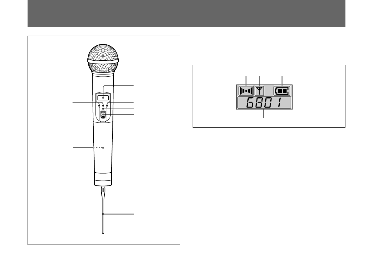
1 Wind screen
Protects against noise caused by wind.
2 Liquid-crystal display
ABDC
AF RF BATT
8
3
4
5
Display example
for U68 model
A AF (audio input) indication
7
Lights whenever an audio signal stronger than the reference
level is received.
B RF (antenna output) indication
Lights during signal transmission from the antenna.
C BATT (battery) indication
Shows the battery condition.
See “Battery indication” on page 7.
6
US
4
Page 7
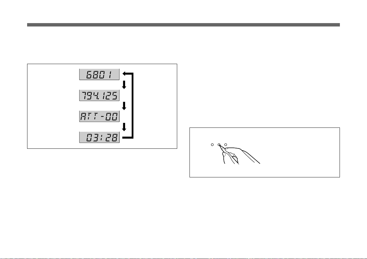
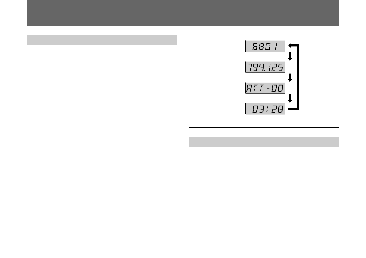
D CH (channel) indication
Displays the transmitting channel.
Each time you press the SET button in Transmit mode, the
channel indication changes as follows.
To adjust these parameters, see “Changing the Transmitting
Channel” on page 5, “Changing the Input Attenuation
Setting” on page 10 or “Resetting the Accumulated Battery
Use Time Indication” on page 11.
Transmitting
channel
Transmitting
frequency
Attenuation level
Accumulated
battery use time
Press SET button.
Display example
for U68 model
Transmitting channel: The current transmitting channel
setting.
Transmitting frequency: The current transmitting
frequency setting.
Attenuation: The input attenuation setting in decibels.
Can be set within a range of 0 dB to 21 dB in 3-dB
steps.
Accumulated battery use time: The accumulated time of
battery use (in 1-minute increments).
3 SET button
In Transmit mode, press this button to change the indicated
items in the lower half of the liquid-crystal display.
To change to Setting mode, turn the POWER switch to ON
while holding this button down. Then press this button to
select the items to be indicated.
How to press the SET and +/– buttons
+
SET
–
Press the button with a
ballpoint pen or similar item.
For details on Setting mode, see “Settings” on page 8.
5
US
Page 8
Parts Identification
4 POWER indicator
Lights when the microphone is on.
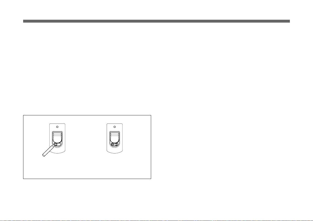
5 POWER switch
Turns the microphone ON or OFF.
When you set this switch to ON without holding down any
other button, the microphone enters Transmit mode, and the
signal of the selected channel is transmitted.
The HOLD switch appears when the POWER switch is set
to ON.
Set the HOLD switch to the lock position to prevent an
accidental power cut-off during microphone operation.
Locking the POWER switch
ON
ON
/
HOLD
.
Slide the HOLD switch to the
right with a ballpoint pen or
similar item.
HOLD
.
A yellow mark appears
when the switch is in the
hold position.
6 Antenna
7 Battery holder
Insert the battery here.
For details on inserting the battery, see “Power Supply” on
page 7.
8 + (+ selection) / – (– selection/reset) buttons
In Setting mode, use these buttons to select the transmitting
channel and attenuation level, and use the – button to reset
the accumulated battery use time indication to 00:00.
For details on Setting mode, see “Settings” on page 8.
US
6
Page 9
Power Supply
The microphone can operate on one LR6 (size AA) alkaline
battery continuously for about 5 hours at 25 ºC (77ºF).
Inserting the battery
e
2
E
1,3
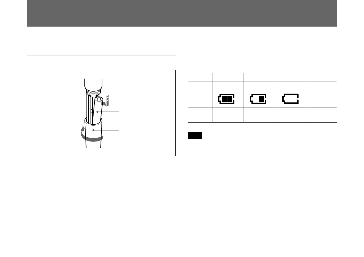
1 Turn the grip in the direction of the arrow to open the
battery holder.
2 Match the battery to the polarity markings and insert it
into the battery holder.
3 Close the battery holder and lock the grip by turning it
in the opposite direction of the arrow.
Battery indication
When you turn the power on, the battery condition is
indicated by the BATT indication in the liquid-crystal
display.
1234
BATT
indication
Battery
condition
Note
The indication may be incorrect if the battery was not new
when inserted. If you plan to use the microphone for a long
period, replace the battery with a new one.
Lights Lights Flashes Goes off
Good Less than
half-charge
Almost
exhausted
Completely
exhausted
US
7
Page 10
Settings
Initiating Setting Mode
Enter Setting mode to change the transmitting channel, the
transmitting frequency and the attenuation level, or to reset
the accumulated battery use time indication.
To enter Setting mode
While holding down the SET button, turn the POWER
switch to ON.
Hold the SET button down until an indication appears on the
liquid-crystal display.
The microphone enters Setting mode and the indication
before the microphone was previously turned OFF flashes
on the liquid-crystal display.
Pressing the SET button cycles the modes in the order of
Channel selection mode, Frequency selection mode (page
8), Attenuator adjustment mode (page 10) and Accumulated
time indication reset mode (see page 11).
Channel selection
mode
Freqency selection
mode
Press the
Attenuator adjustment
mode
Accumulated time
indication reset mode
SET button.
Display example
for U68 model
Changing the Transmitting Channel
The transmitting channel can be selected through either the
channel number or the frequency.
1 Set the microphone to Setting mode.
If the channel number (or frequency) indication does not
appear, press the SET button until the channel number
(or frequency) indication appears.
US
8
Page 11
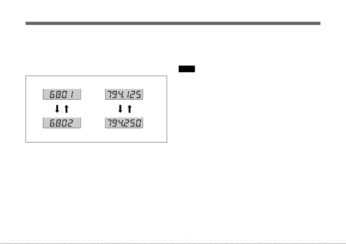
2 Press the + or – button to select the channel number (or
frequency).
Pressing the + button cycles the indication in the order
shown in the tables in Overview of “Wireless Channel
Lists” on page L-1. Pressing the – button cycles the
indications in the opposite direction.
Channel selection mode Freqency selection mode
+ button – button
Hold down the button to change the channel number (or
frequency) quickly.
+ button – button
Display example for U68 model
3 When the desired channel number (or frequency)
appears, turn the POWER switch to OFF to release
Setting mode, or press the SET button to continue
operations in Setting mode.
The next time you turn on the microphone (by turning the
POWER switch to ON), the microphone will enter Transmit
mode with the selected channel number (or frequency).
Notes
• The microphone cannot transmit in Setting mode.
• Make sure that the channel selected on the microphone is
the same as that selected on the tuner being used in the
same system.
• Depending on the noise or interference conditions, all
selectable channels may not be usable. If necessary, you
can determine which channels are usable by cycling the
channel selection through a number of channels on the
tuner with the microphone set to OFF. Those channels for
which the RF indicator on the tuner does not light are
usable.
• The microphone may not operate correctly if it is turned
on immediately after being turned off in Setting mode.
Wait for a few seconds before turning the power on again.
US
9
Page 12
Setting
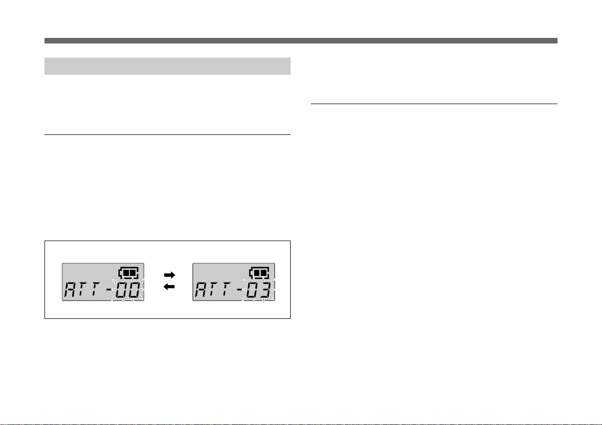
Changing the Input Attenuation Setting
The input attenuation setting can be changed within a range
of 0 dB to 21 dB (in 3-dB steps) in either Setting mode or
Transmit mode.
Changing the input attenuation in Setting
mode
1 Set the microphone to Setting mode.
2 If the attenuation level is not displayed, press the SET
button until it appears.
3 Press the + or – button to change the attenuation setting.
AF RF BATT AF RF BATT
Hold down the button to change the level quickly.
+ button
– button
The next time you turn on the microphone (by turning the
POWER switch to ON), the microphone enter Transmit
mode with the selected attenuation setting.
Changing the input attenuation in Transmit
mode
You can also change the input attenuation setting while
transmitting in Transmit mode.
1 If the attenuation level is not displayed, press the SET
button until it appears.
2 Press the + or – button to change the attenuation setting.
4 Once the desired level appears, turn the POWER switch
to OFF to release Setting mode, or press the SET button
to continue operations in Setting mode.
US
10
Page 13
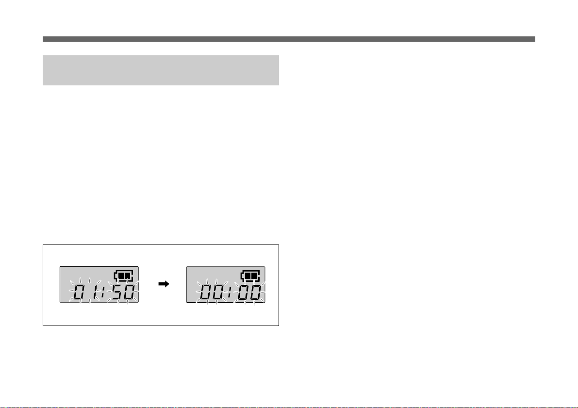
Resetting the Accumulated Battery Use
Time Indication
The accumulated battery use time is the total time (in hours
and minutes) the battery has been used. It is recorded
whenever the WRT-807A is on.
Reset the indication to 00:00 whenever you replace the
battery.
1 Set the microphone to Setting mode.
2 If the accumulated battery use time is not displayed,
press the SET button until it appears.
3 Press the – button.
The indication resets to 00:00.
4 Turn the POWER switch to OFF to release Setting
mode.
AF RF BATT
– button
Press the + button while the 00:00 indication is on to go
back to previous value.
AF RF BATT
11
US
Page 14

Troubleshooting
If you have any problem using this unit, use the following checklist. Should any problem persist, consult your Sony dealer.
Symptom Meaning/Remedy
The microphone does not turn on. • The + and – poles of the battery do not match those of the battery compartment. b Insert the
The battery runs down quickly. • The battery is exhausted. b Replace the battery with new one.
The microphone cannot be turned
off.
The channel cannot be changed. An attempt was made to change the channel by pressing the SET button only. b Turn the
There is no sound. • The indication on the LCD is flashing. b The microphone is in channel setting mode. Turn the
battery with the poles correctly matched.
• The battery is exhausted. b Replace the battery with new one.
• The battery terminals in the microphone are dirty. b Clean the + and – terminals with a cotton
swab.
• A manganese battery is being used. b Use an alkaline battery. The battery life of a manganese
battery is less than half that of an alkaline battery.
• The microphone is being used under cold conditions. b The battery runs down quickly under cold
conditions.
The HOLD switch is in locked position. b Change the HOLD switch to the unlocked position.
microphone off, then turn the microphone on again while holding down the SET button. Then
change the channel with the + and – buttons.
power off, then on again.
• The channel setting on the microphone is different from that on the tuner. b Use the same channel
setting for both the microphone and tuner.
• The AF or RF indicator does not turn on. b Confirm that the microphone and tuner are both turned
on.
12
US
Page 15

Symptom Meaning/Remedy
The sound is weak.
There is distortion in the sound. The attenuation level setting is too low. b The input level is extremely high. Press the + button in
There is sound interruption or
noise.
• The attenuation level setting is too high. b The output level is low. Press the – button in attenuation
level setting mode to lower the attenuation level.
• The volume on the amplifier, mixer or tuner is low. b Adjust the volume.
attenuation level setting mode to raise the attenuation level.
• The receiver’s antenna is incorrectly connected. b Connect the antenna correctly according to the
operation manual of the tuner or antenna divider.
• The antenna divider is turned off. b Turn the antenna divider on. It is possible for the tuner to
receive signals even when the antenna divider is turned off, but sound interruption or noise may
occur.
• The RF indicator lights even when the microphone is off. b Jammed transmissions are being
received. Determine which channels are usable (i.e., channels for which the RF indicator on the
tuner does not light) and set the tuner and microphone to the same usable channel.
• Two or more microphones are set to the same channel. b Make sure no two microphones are set to
the same channel. Set each microphone to a different channel.
13
US
Page 16

Specifications
Transmitter and modulator section
Oscillator Crystal controlled PLL
synthesizer
Type of emission F3E
Carrier frequencies
U64 model: 770.125 to 781.875 MHz
(TV channels 64 and 65)
U66 model: 782.125 to 793.875 MHz
(TV channels 66 and 67)
U68 model: 794.125 to 805.875 MHz
(TV channels 68 and 69)
RF power output 10 mW (50-ohm load)
Tone signal 32.768 kHz
Battery condition signal 32.782 kHz
Type of antenna 1/4 -wavelength wire
Audio section
Microphone type uni-directional dynamic
microphone
Pre-emphasis 50 µs
Deviation ±5 kHz (94 dBSPL1), 1 kHz input)
Frequency response 50 to 15,000 Hz
Signal-to-noise ratio 57 dB or more (A-weighted,
modulation frequency 1 kHz,
with ±5 kHz deviation at WRR-
800A/801A)
Audio attenuator 0 to 21 dB, variable in 3-dB
steps
Input level 151 dBSPL
. . . . . . . . . . . . . . . . . . . . . . . . . . . . . . . . . . . . . . . . . . . . . . . . . . . . . . . . . . . . . . . . . . . . . . . . . . . . . . . . . . . . . . . . . . . . . . . . . . . . . . . . . . . . . . . . . . . . . . . . . . . . . . .
1) 0 dBSPL = 2 × 10⁻⁵ Pa
US
14
(at audio attenuator 21 dB)
Power section
Power requirements 1.5 V DC
(one LR6/size AA alkaline
battery)
Battery life Approx. 5 hours at 25°C or
77°F, with Sony LR6 alkaline
battery
General
Operating temperature 0°C to +50°C (32°F to 122°F)
Storage temperature –30°C to +60°C (–22°F to
+140°F)
Dimensions 51 × 238 mm (diameter/length)
not including antenna
(2-1/8 × 9-3/8 inches)
Mass Approx. 440 g (15.5 oz)
including battery
Supplied accessory
Operating Instructions (1)
Microphone holder (1)
Screw adaptor PF 1/2 to NS 5/8 (1)
Design and specifications are subject to change without
notice.
Page 17
Error Messages
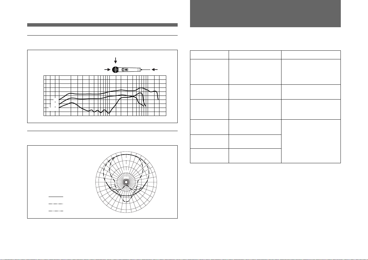
Standard frequency response
90°
dB
20
10
0
–10
0°
90°
–20
180°
–30
20 50 100 200 500 1k 2k 5k 10k 20k Hz
0° 180°
Standard directivity response
0°
0dB
30° 30°
–5
60° 60°
90° 90°
100 Hz
1 kHz
6 kHz
–10
–15
–20
180°
When a problem occurs, one of the following error
messages may appear on the display.
Message Contents Measures
Error 11 An error occurred in
backup memory data.
Error 21 The PLL synthesized
circuit is in trouble.
Error 31 The battery voltage
exceeds the allowable
value.
Error 41 Defect of an internal
circuit.
Error 51 Defect of the A/D
converter circuit.
Error 61 Defect of an internal
circuit.
120°120°
150°150°
The data was initialized.
Set the transmitting
channel and the input
attenuation again.
Contact your Sony
dealer.
Use the specified battery.
Contact your Sony
dealer.
15
US
Page 18

Page 19

Español
Índice
Precauciones
Precauciones............................................................. 1
Introducción .............................................................. 2
Características ...................................................2
Identificación de piezas............................................ 4
Fuente de alimentación ............................................7
Ajustes .......................................................................8
Activación del modo de ajuste ..........................8
Cambio del canal de transmisión ......................8
Cambio del ajuste de atenuación de entrada ...10
Reposición de la indicación de tiempo de uso
acumulado de la pila ..................................11
Localización de averías .......................................... 12
Especificaciones ..................................................... 14
Mensajes de error ................................................... 15
• La unidad ha sido diseñada para emplearse dentro de un
entorno de temperaturas ambientes de 0ºC a 50ºC (32ºF a
122ºF).
• No coloque la unidad en o cerca de fuentes de calor tales
como lámparas amplificadores de potencia o en un lugar
expuesto a los rayos del sol o humedad excesivo. Estos
lugares pueden afectar la terminación exterior o las piezas
en el interior de la unidad.
• Si se utiliza la unidad en lugares muy húmedos o con
mucho polvo o si se coloca en un lugar expuesto al gas,
limpie bien su superficie y los conectores con un paño seco
y suave, después del uso. Un uso prolongado de la unidad
en dichos lugares o si no la limpia después de utilizarla en
tales lugares, puede acortar su longevidad.
• Cuando limpie la unidad no utilice solventes orgánicos
tales como diluyentes o bencina que puedan dañar el
acabado e la unidad.
• La unidad ha sido ajustada precisamente en fábrica. No
debe tocar o tratar de reparar sus piezas interiores.
• No trate de recargar una pila alcalina.
• No eche una pila al fuego. No desarme o cortocircuite los
polos de una pila.
• Utilice siempre una pila alcalina LR6 (tamaño AA).
• Confirme que los polos de la pila coinciden con las marcas
+ y – del portapila.
• Saque la pila si no va a utilizar la unidad durante un largo
período de tiempo.
ES
Espa
ñol
ES
1
Page 20

Introducción
El WRT-807A es un micrófono inalámbrico con
sintetización UHF para utilizar en la banda de 800 MHz
para sistemas de micrófono inalámbrico con sintetización
UHF.
El WRT-807A se utiliza en combinación con el sintonizador
de sintetización UHF WRR-800A/801A/802A/805A, MB806A para concentrar la voz.
El WRT-807A también puede utilizarse con los sistemas de
micrófono inalámbricos de Sony compuestos por el
transmisor sintetizado de UHF WRT-810A/820A/822A/
830A y el sintonizador sintetizado de UHF WRR-810A/
820A/840A/850A.
El micrófono/transmisor y los sintonizadores del sistema de
micrófono inalámbrico están clasificados por banda de
frecuencia.
Se asigna una banda de frecuencia de 12 MHz (o dos
canales de televisión de número consecutivo como el 68 y
69 del modelo U68) para cada modelo de micrófono/
transmisor y sintonizador que posean el mismo número de
canal de TV.
Cuando se diseña un sistema de micrófonos inalámbricos
UHF, asegúrese de combinar un micrófono/transmisor con
un sintonizador que tenga el mismo número de canal de TV.
Con respecto a los canales inalámbricos y las frecuencias
seleccionables, consulte las “Listas de canales
inalámbricos” de la página L-1.
ES
2
Características
Sistema de sintonización con bucle de fase
cerrado (PLL)
El WRT-807A tiene un refinado circuito con sintetización
de bucle de fase cerrado (PLL).
Interruptor principal POWER con función de
retención
El interruptor POWER puede bloquearse en la posición ON
para protegerlo contra cortes eléctricos accidentales.
Aviso de poca carga de la pila en el sintonizador
Cuando la pila en el micrófono tiene poca carga, él
micrófono envía una advertencia al WRR-800A/801A/
802A/805A/850A, MB-806A como “Información sobre el
estado de la pila”.
Esta información se envía al WRR-800A/801A/802A/805A/
850A, MB-806A aproximadamente una hora antes de
agotarse la pila para darle tiempo para cambiar la pila.
Cuando el WRR-800A/801A/802A/805A/850A, MB-806A
reciben esta información, el LED y LCD en el panel del
sintonizador empiezan a parpadear.
Alimentación eléctrica con pilas de gran difusión
El convertidor de CC-CC de gran eficacia incorporado
permite la operación estable durante cinco horas continuas,
con una sola pila alcalina LR6 (tamaño AA).
Page 21

Visualización de cristal líquido para variada
información
El visualizador de cristal líquido del micrófono mostrará el
número del canal actual, la frecuencia, ajuste de atenuación
de entrada y carga residual de la pila.
Se indica también el tiempo de uso acumulado de la pila (en
incrementos de un minuto) para un control preciso del uso
de la pila.
Memorización automática de ajustes de canal y
atenuación de entrada
Todos los canales y ajustes de atenuación de entrada se
memorizan automáticamente cuando se desconecta el
micrófono (y se mantienen aunque se saque la pila),
eliminando la necesidad de volver a hacer los mismos
ajustes de nuevo cuando vuelva a utilizar el micrófono.
Atenuador electrónico de gran fiabilidad
El atenuador de nivel de entrada incorporado podrá ajustarse
dentro de un margen de 0 dB a 21 dB en pasos de 3 dB,
reduciendo la distorsión de la señal cuando se recibe una
señal de entrada de gran intensidad.
Señal de portadora de RF con señal de tono
incorporada
El micrófono transmite una señal de portadora de RF que
incorpora una señal de tono para permitir que cualquier
sintonizador con un circuito silenciador de tono pueda
recibir solamente la señal de audio pretendida.
Amplia gama dinámica y bajo ruido
El sistema compansor (comprensor/expansor) permite la
transmisión en una amplia gama dinámica con el ruido
mínimo.
Notas sobre el funcionamiento
• Cuando se utilizan dos o más micrófono mantenga los
micrófonos separados entre sí en una distancia de por lo
menos 30 cm (1 pie).
• Mantenga los micrófonos a por lo menos 3 metros
(10 pies) de la antena de recepción.
ES
3
Page 22

Identificación de piezas
1
2
1 Pantalla contra el viento
Protege contra el ruido provocado por el viento.
2 Visualizador de cristal líquido
ABDC
AF RF BATT
8
3
4
5
Ejemplo de
visualización para
el modelo U68
A Indicación de entrada de audio (AF)
7
Se enciende cada vez que se recibe una señal de audio más
fuerte que el nivel de referencia.
B Indicación de salida de antena (RF)
Se enciende durante la transmisión de una señal a través de
la antena.
C Indicación de la pila (BATT)
Muestra el estado de la pila
6
ES
4
Consulte “Indicación de pila” de la página 7.
Page 23

D Indicación de canal (CH)
Muestra el canal de transmisión.
Cada vez que presione la tecla SET en el modo de
transmisión, la indicación de canal cambiará de la siguiente
forma.
Canal de
transmisión
Frecuencia de
transmisión
Presione la tecla
Nivel de
atenuación
Tiempo de uso
acumulado de la
pila
SET.
Ejemplo de
visualización para
el modelo U68
Canal de transmisión: El ajuste actual del canal de
transmisión.
Frecuencia de transmisión: El ajuste actual de frecuencia
de la transmisión.
Atenuación: El ajuste de atenuación de entrada en
decibelios. Puede ajustarse en un entorno de 0 dB a 21
dB en pasos de 3 dB.
Tiempo de uso acumulado de la pila: El tiempo de uso
acumulado de la pila (en incrementos de 1 minuto).
Para ajustar estos parámetros, vea el “Cambio del canal de
transmisión” de la página 5, “Cambio del ajuste de
atenuación de entrada” de la página 10 o la “Reposición de
la indicación de tiempo de uso acumulado de la pila” de la
página 11.
3 Tecla de ajuste (SET)
En el modo de transmisión, presione esta tecla para cambiar
los ítems de indicación de la mitad inferior del visualizador
de cristal líquido.
Para cambiar el modo de ajuste, ponga el interruptor
POWER a ON mientras mantiene presionada esta tecla.
Presione este botón para seleccionar el ítem que desee que
aparezca.
Forma de presionar las teclas SET y +/–
+
SET
–
Presione la tecla con un
bolígrafo o ítem similar.
Para más detalles sobre el modo de ajuste, vea los
“Ajustes” de la página 8.
ES
5
Page 24

Identificación de piezas
4 Indicador POWER
Se enciende cuando se está utilizando el micrófono.
5 Interruptor de alimentación (POWER)
Utilícelo para conectar y desconectar el micrófono.
Cuando ponga este interruptor en ON sin mantener
presionada ninguna otra tecla, el micrófono pasará al modo
de transmisión y se transmitirá la señal del canal
seleccionado.
Aparece el interruptor HOLD cuando el interruptor POWER
está en ON.
Ajuste el interruptor HOLD a la posición de bloqueo para
evitar que se cortd accidentalmente la alimentación mientras
está utilizando el micrófono.
Bloqueo del interruptor POWER
ON
ON
/
HOLD
.
Deslice el interruptor HOLD en
el lado derecho con un bolígrafo
o similar.
HOLD
.
Aparece una arca amarilla
cuando el interruptor está
en la posición de retención.
6 Antena
7 Portapila
Coloque la pila aquí.
Para más detalles sobre la colocación de la pila, consulte la
“Fuente de alimentación” de la página 7.
8 Teclas de selección (+)/selección/reposición (–)
En el modo de ajuste, utilice estas teclas para seleccionar el
canal de transmisión y el nivel de atenuación, y utilice la
tecla (–) para reponer la indicación de tiempo de uso
acumulado de la pila a 00:00.
Para más detalles sobre el modo de ajuste, consulte los
“Ajustes” de la página 8.
ES
6
Page 25

Fuente de alimentación
El micrófono puede funcionar con una pila alcalina LR6
(tamaño AA) durante unas 5 horas continuas a 25ºC (77ºF).
Inserción de la pila
e
2
E
1,3
1 Gire la empuñadura en el sentido de la flecha para abrir
el portapila.
2 Alinee la pila con las marcas de polaridad y colóquela
en el portapila.
3 Cierre el portapila y fije la empuñadura girándola en el
sentido contrario de la flecha.
Indicación de pila
Cuando conecte la alimentación, en la indicación BATT del
visualizador de cristal líquido aparecerá el estado de la pila.
123 4
Indicación
BATT
Estado de
la pila
Nota
La indicación puede ser incorrecta si la pila insertada no es
nueva. Cuando planee utilizar el micrófono durante mucho
tiempo, lo mejor será que reemplace la pila por otra nueva.
Encendida Encendida Parpadeando Apagada
Bueno
Menos de
la mitad de
la carga
Prácticamente
agotada
Completamente
agotada
ES
7
Page 26

Ajustes
Activación del modo de ajuste
En el modo de ajuste podrá cambiar el canal de transmisión
y el nivel de atenuación o reponer la indicación de tiempo de
uso acumulado de la pila.
Para entrar en el modo de ajuste
Mantenga presionada la tecla SET y ponga el interruptor
POWER en ON.
Mantenga presionada la tecla SET hasta que en el
visualizador aparezca una indicación.
El micrófono entrará en el modo de ajuste y en el
visualizador de cristal líquido parpadeará la indicación
existente al momento de desconectar (OFF) la alimentación
del micrófono.
Cada vez que presione la tecla SET, cambiarán cíclicamente
el modo de selección de canal, el modo de selección de
frecuencia (página 8), el modo de ajuste de atenuación
(página 10) y el modo de reposición de la indicación de
tiempo acumulado (página 11).
Modo de selección de
canal
Modo de selección de
frecuencia
Presione la
Modo de ajuste de
atenuador
Modo de reposición de
la indicación de tiempo
acumulado
tecla SET.
Ejemplo de
visualización para el
modelo U68
Cambio del canal de transmisión
El canal de transmisión puede seleccionarse tanto por el
número de canal como por la frecuencia.
1 Ponga el micrófono en el modo de ajuste. Si no se
visualiza la indicación de número de canal (o
frecuencia), presione la tecla SET hasta que visualice la
indicación del número de canal (o la frecuencia).
ES
8
Page 27

2 Presione la tecla + o – para seleccionar el número de
canal (o frecuencia).
Al presionar la tecla + la indicación cambiará
cíclicamente en el orden mostrado en la tabla “Lista de
canales inalámbricos” de la página L-1. Cada vez que
presione la tecla – cambiará en el orden inverso.
Modo de selección de canal Modo de selección de
tecla + tecla –
frecuencia
tecla + tecla –
Ejemplo de visualización para el
modelo U68
Si mantiene presionada cualquiera de las teclas, el
número de canal (o la frecuencia) aumentará
rápidamente.
3 Cuando se visualiza el número de canal (o frecuencia)
deseado, ponga el interruptor POWER en OFF para salir
del modo de ajuste, o presione la tecla SET para seguir
con otras operaciones en el modo de ajuste.
La próxima vez que conecte el micrófono (con el interruptor
POWER en ON) el micrófono entrará al modo de
transmisión con el número de canal (o frecuencia)
seleccionado.
Notas
• El micrófono no podrá transmitir en el modo de ajuste.
• Cerciórese de que el canal seleccionado sea el mismo que
el elegido en el sintonizador utilizado en el mismo sistema.
• Dependiendo de las condiciones de ruido de interferencias,
es posible que no puedan utilizarse todos los canales
seleccionables. Si es necesario podrá determinar los
canales utilizables pasando cíclicamente por los números
de canal en el sintonizador con el micrófono desconectado
(OFF). Los canales en los que el indicador de RF del
sintonizador no se encienda serán los que podrán utilizarse.
• Es posible que el micrófono no funcione correctamente si
conecta su alimentación inmediatamente después de
haberla desconectado estando en el modo de ajuste. Espere
algunos segundos antes de volver a conectar la
alimentación.
ES
9
Page 28

Ajustes
Cambio del ajuste de atenuación de entrada
Se podrá cambiar el ajuste de la atenuación de entrada
dentro de un margen de 0 dB a 21 dB (en pasos de 3 dB) en
el modo de ajuste o en el modo de transmisión.
Cambio de la atenuación de entrada en el
modo de ajuste
1 Ponga el micrófono en el modo de ajuste.
2 Si no se visualiza el nivel de atenuación, presione la
tecla SET hasta que aparezca.
3 Presione la tecla + o – para seleccionar el ajuste de
atenuación.
AF RF BATT AF RF BATT
tecla +
tecla –
4 Cuando visualice el nivel deseado, ponga el interruptor
POWER en OFF para salir el modo de ajuste o presione
la tecla SET para continuar las operaciones en el modo
de ajuste.
La próxima vez que conecte el micrófono (poniendo el
interruptor POWER en ON), el micrófono entrará en el
modo de transmisión con el ajuste de atenuación
seleccionado.
Cambio de la entrada de atenuación en el
modo de transmisión
Se puede ajustar la atenuación de entrada mientras transmite
en el modo de transmisión.
1 Si no se visualiza el nivel de atenuación, presione la
tecla SET hasta que aparezca.
2 Presione la tecla + o – para seleccionar el ajuste de
atenuación.
Si mantiene presionada cualquiera de las teclas, el nivel
cambiará rápidamente.
ES
10
Page 29

Reposición de la indicación de tiempo
de uso acumulado de la pila
La indicación de tiempo de uso acumulado de la pila es el
tiempo total (en horas y minutos) de utilización de la pila.
Se registra siempre que el WRT-807A esté conectado.
Reponga la indicación a 00:00 cada vez que reemplace la
pila.
1 Ponga el micrófono en el modo de ajuste.
2 Si el tiempo acumulado de utilización no se visualiza,
presione la tecla SET hasta que aparezca.
3 Presione la tecla –.
La indicación se repone a 00:00.
4 Ponga el interruptor POWER en OFF para salir del
modo de ajuste.
AF RF BATT
tecla –
Mientras esté viendo la indicación “00:00” podrá volver
al valor anterior presionando la tecla +.
AF RF BATT
11
ES
Page 30

Localización de averías
Si tiene problemas para el uso de este aparato, recurra a la siguiente lista de comprobación. Si no puede solucionar el
problema, consulte con su proveedor de Sony.
Síntoma Significado/Solución
El micrófono no se conecta. • Los polos + y – de la pila no coinciden con los dibujados en el portapila. b Coloque la pila con las
La pila se consume
rápidamente.
El micrófono no se puede
desconectar.
No puede cambiar el canal. Se ha tratado de cambiar el canal presionando sólo la tecla SET. b Desconecte el micrófono una
No hay sonido. • La indicación en el visualizador de cristal líquido está parpadeando. b El micrófono está en el
polaridades en el sentido correcto.
• La pila está gastada. b Cambie la pila por otra nueva.
• Los terminales de pila en el micrófono están sucios. b Limpie los terminales + y – con un algodón.
• La pila está gastada. b Cambie la pila por otra nueva.
• Se está utilizando una pila de manganeso. b Utilice una pila alcalina. La vida de la pila de
manganeso es menor a la de la pila alcalina.
• Se está utilizando el micrófono en clima frío. b La pila se gasta rápidamente cuando hace frío.
El interruptor HOLD está en la posición de bloqueo. b Cambie el interruptor HOLD a la posición de
desbloqueo.
vez y vuelva a conectar mientras mantiene presionada la tecla SET. Cambie el canal con las teclas
+ y –.
modo de ajuste de canal. Desconecte la alimentación y vuelva a conectar.
• El ajuste de canal del micrófono es diferente del canal en el sintonizador. b Utilice el mismo ajuste
de canal para el micrófono y el sintonizador.
• El indicador AF o RF no se conecta. b Confirme que el micrófono y el sintonizador están
sintonizados.
12
ES
Page 31

Síntoma Significado/Solución
El sonido se escucha bajo. • El nivel de atenuación está demasiado alto. b El nivel de salida está bajo. Presione la tecla – en el
Hay distorsión en el sonido. El ajuste de nivel de atenuación está demasiado bajo. b El nivel de entrada está muy alto. Presione
Hay cortes en el sonido o ruido. • La antena del receptor está mal conectada. b Conecte correctamente la antena de acuerdo al
modo de ajuste de nivel de atenuación para bajar el nivel de la atenuación.
• El volumen del amplificador, mezclador o sintonizador está bajo. b Ajuste el volumen.
la tecla + en el modo de ajuste de nivel de atenuación para subir el nivel de atenuación.
manual de instrucciones del sintonizador o bifurcador de antena.
• El bifurcador de antena está desactivado. b Conecte el bifurcador de antena. Es posible que el
sintonizador reciba las señales incluso cuando el bifurcador de antena está desactivado pero se
pueden producir cortes del sonido o ruidos.
• El indicador de RF se enciende aunque el micrófono esté desconectado. b Se reciben
transmisiones de interferencia. Determine los canales que pueden utilizarse (es decir, los canales
para los que el indicador de RF en el sintonizador no se enciende) y ajuste el sintonizador y el
micrófono al mismo canal utilizable.
• Se utilizan dos o más micrófonos en el mismo canal. b Cerciórese de que no hay dos micrófonos
en el mismo canal. Ajuste cada micrófono a un canal diferente.
13
ES
Page 32

Especificaciones
Sección del transmisor y modulador
Oscilador Sintonizador de PLL controlado
por cristal
Tipo de transmisión F3E
Frecuencias portadoras
modelo U64: 770,125 a 781,875 MHz
(Canales de TV 64 y 65)
modelo U66: 782,125 a 793,875 MHz
(Canales de TV 66 y 67)
modelo U68: 794,125 a 805,875 MHz
(Canales de TV 68 y 69)
Salida de potencia de RF 10 mW (carga de 50 ohmios)
Señal de tono 32,768 kHz
Señal de estado de la pila 32,782 kHz
Tipo de antena
Sección de audio
Tipo de micrófono dinámico unidireccional
Preacentuación 50 µs
Desviación ±5 kHz (94 dBSPL1), entrada a
Respuesta de frecuencia 50 a 15.000 Hz
Relación de señal a ruido 57 dB o más (ponderación A,
Atenuador de ruido 0 a 21 dB, variable en pasos de
. . . . . . . . . . . . . . . . . . . . . . . . . . . . . . . . . . . . . . . . . . . . . . . . . . . . . . . . . . . . . . . . . . . . . . . . . . . . . . . . . . . . . . . . . . . . . . . . . . . . . . . . . . . . . . . . . . . . . . . . . . . . . . .
1) 0 dBSPL = 2 × 10⁻⁵ Pa
ES
14
Cable de 1/4 de longitud de onda
1 kHz)
frecuencia de modulación de 1
kHz, con desviación de ±5 kHz
en WRR-800A/801A)
3 dB
Nivel de entrada 151 dBSPL
(con atenuador de audio de
21 dB)
Sección de alimentación
Requisitos eléctricos CC de 1,5 V
(una pila alcalina LR6/tamaño AA)
Duración de la pila Aprox. 5 horas a 25ºC o 77ºF
con pila alcalina LR6 de Sony
Generalidades
Temperatura de funcionamiento
0ºC a +50ºC (32ºF a 122ºF)
Temperatura de almacenamiento
–30ºC a +60ºC (–22ºF a
+140ºF)
Dimensiones 51 × 238 mm (diámetro/
longitud) sin incluir la antena)
(2-1/8 × 9-3/8 pulg.)
Peso Aprox. 440 g (15,5 onzas)
incluyendo la pila
Accesorio suministrado
Manual de instrucciones (1)
Soporte de micrófono (1)
Adaptador de tornillo PF 1/2 a NS 5/8 (1)
El diseño y las especificaciones están sujetos a cambios sin
previo aviso.
Page 33

Mensajes de error
Respuesta de frecuencia estándar
90°
dB
20
10
0
–10
0°
90°
–20
180°
–30
20 50 100 200 500 1k 2k 5k 10k 20k Hz
0° 180°
Repuesta de directividad estándar
0°
0dB
30° 30°
–5
60° 60°
90° 90°
100 Hz
1 kHz
6 kHz
–10
–15
–20
180°
Cuando ocurra un problema, es posible que en el
visualizador aparezca uno de los mensajes de error
siguientes.
Mensajes Contenido Medidas
Error 11 Se ha producido un
error en los datos de
la memoria de
respaldo.
Error 21 El circuito sintetizado
de bucle de enganche
de fase está averiado.
Error 31 La tensión de la pila
sobrepasa el valor
permisible.
Error 41 Defecto en un circuito
interno.
Error 51 Defecto en el circuito
del convertidor A/D.
Error 61 Defecto en un circuito
interno.
120°120°
150°150°
Los datos se han
inicializado. Vuelva a
ajustar el canal de
transmisión y la
atenuación de entrada.
Póngase en contacto con
su proveedor Sony.
Utilice la pila
especificada.
Póngase en contacto con
su proveedor Sony.
15
ES
Page 34

Page 35

Français
Table des matières
Précautions
Précautions................................................................1
Introduction ...............................................................2
Caractéristiques .................................................2
Identification des pièces .......................................... 4
Alimentation .............................................................. 7
Réglages ....................................................................8
Passage au mode de réglage ..............................8
Changement de canal de transmission ..............8
Modification du réglage d’atténuation d’entrée ..
...................................................................10
Remise à zéro de l’indication du temps
d’utilisation total de la pile ........................11
Dépannage............................................................... 12
Spécifications.......................................................... 14
Messages d’erreur .................................................. 15
• Cet appareil est conçu pour être utilisé à une température
ambiante allant de 0 à 50˚C (32 à 122˚F).
• Ne placez pas cet appareil sur ou près d’une source de
chaleur, telle qu’appareil d’éclairage, amplificateur de
puissance, ou à un autre endroit en plein soleil ou soumis à
une très forte humidité. A de tels endroits, la finition ou
des composants internes risqueraient d’être endommagés.
• N’utilisez pas cet appareil à un endroit très humide ou
poussiéreux, ou en présence d’un gaz actif. Nettoyez sa
surface ainsi que les connecteurs avec un chiffon sec et
doux immédiatement après l’utilisation.
L’emploi de longue durée de l’appareil à de tels endroits
pourrait réduire sa vie de service.
• N’employez jamais de solvant organique, tel que diluant
ou benzène pour nettoyer l’appareil; ces produits
pourraient endommager la finition.
• Cet appareil a été précisément ajusté à l’usine. Ne modifiez
pas les composants internes et n’essayez pas de le réparer.
• Ne jetez pas les piles au feu. Ne les démontez pas et ne
court-circuitez pas.
• Utilisez bien une pile alcaline LR6 (format AA).
• Vérifiez que les pôles de la piles correspondent aux
marques + et – dans le logement de la pile.
• Retirez la pile quand l’appareil doit rester inutilisé pendant
une période prolongée.
FR
Français
FR
1
Page 36

Introduction
Le WRT-807A est un microphone sans fil synthétisée UHF
à utiliser dans un système de microphone sans fil synthétisé
UHF à bande 800 MHz.
Le WRT-807A fonctionne conjointement avec le
syntoniseur synthétisé WRR-800A/801A/802A/805A, MB806A pour la concentration vocale.
Le WRT-807A peut aussi être utilisé avec les systèmes de
microphone sans fil Sony existants comprenant un émetteur
synthétisé UHF WRT-810A/820A/822A/830A et un
syntoniseur synthétisé UHF WRR-810A/820A/840A/850A.
Le microphone/émetteur et les syntoniseurs du système de
microphone sans fil sont classés par bande de fréquences.
Une bande de fréquences de 12 MHz (ou deux canaux de
télévision à numéros consécutifs, tels que 68 et 69 du
modèle U68) est assignée à chaque modèle de microphone/
émetteur et syntoniseur.
Combinez bien un microphone/émetteur et un syntoniseur
ayant le même numéro de canal de télévision lors de la
création d’un système de microphone sans fil UHF.
Voir la “Listes des canaux sans fil” à la page L-1 pour les
canaux sans fil et les fréquences sélectionnables.
Caractéristiques
Système synthétisé à boucle à verrouillage de
phase (PLL)
Le WRT-807A est doté d’un circuit à verrouillage de phase
(PLL) sophistiqué.
Interrupteur POWER à fonction de maintien
L’interrupteur POWER peut être verrouillé en position ON
pour éviter toute coupure de courant accidentelle.
Indication d’affaiblissement de la pile sur le
syntoniseur
Quand la pile du microphone est affaiblie, le microphone
envoie un avertissement au WRR-800A/801A/802A/805A/
850A, MB-806A sous forme “d’information d’état de la
pile”.
Cette information est envoyée au WRR-800A/801A/802A/
805A/850A, MB-806A environ une heure avant
l’épuisement de la pile pour permettre son remplacement en
toute sécurité.
Quand le WRR-800A/801A/802A/805A/850A, MB-806A
reçoit cette information, les DEL et l’affichage du panneau
du syntoniseur se mettent à clignoter.
Alimenté par un type de pile facilement disponible
Le convertisseur C.C.-C.C. intégré hautement efficace
assure environ cinq heures de fonctionnement continu et
FR
2
stable sur une seule pile alcaline LR6 (format AA).
Page 37

Indication sur afficheur à cristaux liquides (ACL)
de diverses informations
L’ACL du microphone indique le numéro du canal actuel, la
fréquence, le réglage d’atténuation d’entrée et la puissance
restante de la pile.
Le temps d’utilisation total de la pile est également indiqué
(par incréments d’une minute) pour permettre de contrôler
précisément l’usure de la pile.
Sauvegarde automatique des réglages de canal et
d’atténuation d’entrée
Tous les réglages de canal et d’atténuation d’entrée sont
automatiquement sauvegardés à la mise hors tension du
microphone (et sont maintenus même au retrait de la pile),
éliminant ainsi la nécessité de refaire les mêmes réglages à
l’utilisation suivante du microphone.
Atténuateur électronique très fiable
Ajustable sur la plage de 0 à 21 dB par incréments de 3 dB,
l’atténuateur de niveau d’entrée intégré réduit la distorsion
du signal lors de l’entrée de signaux audio trop puissants.
Signal de porteuse RF avec signal de tonalité
Le microphone transmet un signal de porteuse RF
incorporant un signal de tonalité pour permettre à tout
syntoniseur avec circuit de silencieux de capter seulement le
signal audio cible.
Gamme dynamique large et bruit faible
Le compandor (compresseur-expanseur) du microphone
permet la transmission sur une gamme dynamique large
avec un bruit minimum.
Remarques sur le fonctionnement
• Si vous utilisez deux microphones ou plus, maintenez-les
éloignés l’un de l’autre d’au moins 30 cm (1 pied).
• Eloignez les microphones d’au moins 3 mètres (10 pieds)
de l’antenne réceptrice.
FR
3
Page 38

Identification des pièces
1
2
1 Ecran antivent
Protège contre le bruit provoqué par le vent.
2 Afficheur à cristaux liquides (ACL)
ABDC
AF RF BATT
8
3
4
5
Exemple d’affichage
pour le modèle U68
A Indication AF (entrée audio)
7
S’allume à la réception d’un signal audio plus puissant que
le signal de référence.
B Indication RF (sortie d’antenne)
S’allume pendant la transmission du signal de l’antenne.
C Indication BATT (pile)
Indique l’état de la pile.
Voir “Indication d’état de la pile” à la page 7.
6
FR
4
Page 39

D Indication CH (canal)
Affiche le canal de transmission.
A chaque pression du bouton SET en mode de transmission,
l’indication de canal change comme suit.
Voir “Changement de canal de transmission” à la page 5,
“Modification du réglage d’atténuation d’entrée” à la page
10 et “Remise à zéro de l’indication de temps d’utilisation
total de la pile” à la page 11 pour ajuster ces paramètres.
Canal de
transmission
Fréquence de
transmission
Pressez le
Niveau
d’atténuation
Temps d’utilisation
total de la pile
bouton SET.
Exemple
d’affichage pour le
modèle U68
Canal de transmission: Le réglage de canal de
transmission actuel
Fréquence de transmission: Le réglage de fréquence de
transmission actuel
Atténuation: Le réglage d’atténuation en décibels.
Réglable sur la plage de 0 à 21 dB par incréments de
3 dB.
Temps d’utilisation total de la pile: Le temps total
d’utilisation de la pile (par incréments d’1 minute).
3 Bouton de réglage (SET)
En mode de transmission, appuyez sur ce bouton pour
modifier les rubriques indiquées dans la moitié inférieure de
l’ACL.
Pour passer au mode de réglage, mettez l’interrupteur
POWER sur ON en maintenant ce bouton pressé. Puis,
appuyez sur ce bouton pour sélectionner les rubriques à
indiquer.
Pression des boutons SET et +/–
+
SET
–
Appuyez sur ce bouton avec un
stylo à bille ou un objet
similaire.
Voir “Réglages” à la page 8 pour les détails sur le mode de
réglage.
5
FR
Page 40

Identification des pièces
4 Témoin d’alimentation (POWER)
S’allume quand le microphone est sous tension.
5 Interrupteur d’alimentation (POWER)
Met le microphone sous/hors tension.
Si vous mettez cet interrupteur sur ON sans maintenir un
autre bouton enfoncé, le microphone passe en mode de
transmission, et le signal du canal sélectionné est transmis.
Le commutateur HOLD apparaît quand l’interrupteur
POWER est réglé sur ON.
Maintenez le commutateur HOLD en position verrouillée
pour éviter une coupure de courant accidentelle du
microphone pendant son fonctionnement.
Verrouillage de l’interrupteur POWER
ON
ON
/
HOLD
.
Faites glisser le commutateur
HOLD vers la droite avec un
stylo à bille ou un objet similaire.
HOLD
.
Une marque jaune apparaît
quand le commutateur est
en position de maintien.
6 Antenne
7 Logement de la pile
Insérez-y la pile.
Voir “Alimentation” à la page 7 pour les détails sur
l’insertion de la pile.
8 Boutons + (sélection +)/–(sélection –/remise à zéro)
En mode de réglage, sélectionnez le canal de transmission et
le niveau d’atténuation avec ces boutons, et utilisez le
bouton – pour remettre l’indication du temps d’utilisation
total de la pile à 00:00.
Voir “Réglages” à la page 8 pour les détails sur le mode de
réglage.
FR
6
Page 41

Alimentation
Le microphone peut fonctionner en continu pendant environ
5 heures à 25˚C sur une pile alcaline LR6 (format AA).
Insertion de la pile
e
2
E
1,3
1 Tournez la poignée dans le sens de la flèche pour ouvrir
le logement de la pile.
2 Faites correspondre les marques de polarité de la pile
avec celles du logement, et insérez-la dans le logement.
3 Refermez le logement de la pile et verrouillez la
poignée en la tournant dans le sens contraire de la
flèche.
Indication d’état de la pile
A la mise sous tension, l’état de la pile est indiquée par
indication BATT sur l’afficheur à cristaux liquides.
1234
Indication
BATT
Etat de
la pile
Remarque
L’indication peut être incorrecte si la pile n’était pas neuve à
l’insertion. Si vous prévoyez d’utiliser le microphone
pendant une période prolongée, remplacez la pile par une
neuve.
Allumé Allumé Clignotant Eteint
Chargée Moins d’une
demi-charge
Presque
épuisée
Entièrement
épuisée
FR
7
Page 42

Réglages
Passage au mode de réglage
Passez au mode de réglage pour changer de canal de
transmission, de fréquence de transmission et de niveau
d’atténuation, ou pour remettre l’indication du temps
d’utilisation total de la pile à zéro.
Pour passer en mode de réglage
Maintenez le bouton SET pressé et régler l’interrupteur
POWER sur ON.
Maintenez le bouton SET pressé jusqu’à ce qu’une
indication apparaisse sur l’ACL.
Le microphone passe en mode de réglage et l’indication
avant la dernière mise hors tension du microphone clignote
sur l’ACL.
La pression du bouton SET fait passer cycliquement entre
les modes dans l’ordre: mode de sélection de canal, mode de
sélection de fréquence (page 8), mode d’ajustement de
l’atténuateur (page 10) et mode de remise à zéro du temps
d’utilisation total de la pile (page 11).
Mode de sélection de
canal
Mode de sélection de
fréquence
Mode d’ajustement de
l’atténuateur
Mode de remise à zéro
du temps d’utilisation
total de la pile
Appuyez sur
le bouton
SET.
Exemple
d’affichage du
modèle U68
Changement de canal de transmission
La sélection du canal de transmission est possible par le
numéro de canal ou la fréquence.
1 Réglez le microphone au mode de réglage.
Si l’indication du numéro de canal (ou de la fréquence)
n’apparaît pas, appuyez sur le bouton SET jusqu’à ce
qu’elle apparaisse.
FR
8
Page 43

2 Appuyez sur le bouton + ou – pour sélectionner le
numéro de canal (ou la fréquence).
La pression du bouton + modifie cycliquement
l’indication dans l’ordre indiqué dans les tableaux sous
Aperçu des “Listes des canaux sans fil” à la page L-1.
La pression du bouton – fait parcourir cycliquement les
indications en sens opposé.
Mode de sélection de canal
Bouton +
Bouton – Bouton +
Exemple d’affichage pour le modèle U68
Mode de sélection de fréquence
Bouton –
Maintenez le bouton enfoncé pour changer rapidement
de numéro de canal (ou de fréquence).
3 Quand le numéro de canal (ou de fréquence) souhaité
apparaît, mettez l’interrupteur POWER sur OFF pour
quitter le mode de réglage, ou appuyez sur le bouton
SET pour effectuer d’autres opérations en mode de
réglage.
A la mise sous tension suivante du microphone (en mettant
l’interrupteur POWER sur ON), le microphone passera en
mode de transmission avec le niveau de canal (ou la
fréquence) sélectionné.
Remarques
• Le microphone ne peut pas transmettre en mode de
réglage.
• Vérifiez que le canal sélectionné sur le microphone est le
même que celui sélectionné sur le syntoniseur utilisé dans
le même système.
• Selon les conditions de bruit ou d’interférence, les canaux
sélectionnables peuvent ne pas être utilisables. Si
nécessaire, vous pouvez déterminer les canaux utilisables
en parcourant cycliquement la sélection des canaux en
utilisant les numéros de canal sur le syntoniseur avec le
microphone réglé à OFF. Les canaux pour lesquels
l’indicateur RF du syntoniseur ne s’allume pas sont
utilisables.
• Le microphone peut ne pas opérer correctement s’il est
remis sous tension immédiatement après sa mise hors
tension en mode de réglage. Attendez quelques secondes
avant de le remettre sous tension.
FR
9
Page 44

Réglages
Modification du réglage d’atténuation
d’entrée
Le réglage d’atténuation d’entrée peut être modifié sur la
plage de 0 à 21 dB (par incréments de 3 dB) en mode de
réglage ou de transmission.
Modification de l’atténuation d’entrée en mode
de réglage
1 Mettez le microphone en mode de réglage.
2 Si le niveau d’atténuation n’est pas affiché, appuyez sur
le bouton SET jusqu’à ce qu’il apparaisse.
3 Appuyez sur le bouton + ou – pour modifier le réglage
d’atténuation.
AF RF BATT AF RF BATT
Maintenez le bouton pressé pour modifier rapidement le
niveau.
Bouton +
Bouton –
4 Quand le niveau souhaité apparaît, mettez l’interrupteur
POWER sur OFF pour quitter le mode de réglage, ou
appuyez sur le bouton SET pour effectuer d’autres
opérations en mode de réglage.
A la mise sous tension suivante du microphone (en mettant
l’interrupteur POWER sur ON), le microphone passera en
mode de transmission avec le réglage d’atténuation
sélectionné.
Modification de l’atténuation d’entrée en mode
de transmission
L’atténuation d’entrée peut aussi être modifiée pendant la
transmission en mode de transmission.
1 Si le niveau d’atténuation n’est pas affiché, appuyez sur
le bouton SET jusqu’à ce qu’il apparaisse.
2 Appuyez sur le bouton + ou – pour modifier le réglage
d’atténuation.
10
FR
Page 45

Remise à zéro de l’indication du temps
d’utilisation total de la pile
Le temps d’utilisation total de la pile est le temps total (en
heures et minutes) pendant lequel la pile a été utilisée. Il est
enregistré quand le WRT-807A est sous tension.
Remettez l’indication à 00:00 au remplacement de la pile.
1 Mettez le microphone en mode de réglage.
2 Si le temps d’utilisation total de la pile n’est pas affiché,
appuyez sur le bouton SET jusqu’à ce qu’il apparaisse.
3 Appuyez sur le bouton –.
L’indication est remise à 00:00.
4 Mettez l’interrupteur POWER sur OFF pour quitter le
mode de réglage.
AF RF BATT
Appuyez sur le bouton + pendant l’apparition de
l’indication 00:00 pour revenir à la valeur précédente.
Bouton –
AF RF BATT
11
FR
Page 46

Dépannage
En cas de problème avec cet appareil, utilisez la liste de contrôle ci-dessous. Si le problème persiste, consultez votre revendeur
Sony.
Symptôme Signification/mesure à prendre
Le microphone ne se met pas sous
tension.
La pile s’affaiblit rapidement. • La pile est épuisée. b Remplacez-la par une neuve.
La mise hors tension du
microphone est impossible.
Le changement de canal est
impossible.
Pas de son. • L’indication sur l’ACL clignote. b Le microphone est en mode de réglage de canal. Mettez-le hors
• Les pôles + et – de la pile ne correspondent pas à ceux indiqués dans le logement de la pile.
b Insérez la pile en respectant les polarités.
• La pile est épuisée. b Remplacez-la par une neuve.
• Les bornes + et – de la pile du microphone sont sales. b Nettoyez-les avec une ouate de coton.
• Vous utilisez une pile au manganèse. b Utilisez une pile alcaline. La vie de service d’une pile au
manganèse est de moins de la moitié de celle d’une pile alcaline.
• Le microphone est utilisé par temps froid. b La pile s’affaiblit rapidement par temps froid.
Le commutateur HOLD est en position verrouillée. b Mettez-le en position déverrouillée.
Vous avez essayé de changer de canal en appuyant seulement sur le bouton SET. b Mettez le
microphone hors tension, puis à nouveau sous tension en maintenant le bouton SET enfoncé. Puis
changez de canal avec les boutons + et –.
tension, puis à nouveau sous tension.
• Le réglage de canal du microphone est différent de celui du syntoniseur. b Utilisez le même
réglage de canal pour le microphone et le syntoniseur.
• L’indicateur AF ou RF ne s’allume pas. b Vérifiez que le microphone et le syntoniseur sont tous
deux sous tension.
12
FR
Page 47

Symptôme Signification/mesure à prendre
Son faible
Déformation du son • Le niveau d’atténuation est réglé trop bas. b Le niveau d’entrée est très haut. Appuyez sur le
Interruption du son ou bruit • L’antenne du récepteur est mal raccordée. b Raccordez-la correctement conformément au mode
• Le niveau d’atténuation est réglé trop haut. b Le niveau de sortie est faible. Appuyez sur le bouton –
en mode de réglage de niveau d’atténuation pour baisser le niveau d’atténuation.
• Le volume sur l’amplificateur, le mixeur ou le syntoniseur est trop bas. b Ajustez le volume.
bouton + en mode de réglage de niveau d’atténuation pour augmenter le niveau d’atténuation.
d’emploi du syntoniseur ou du diviseur d’antenne.
• Le diviseur d’antenne est hors tension. b Mettez-le sous tension. Le syntoniseur peut capter des
signaux même si le diviseur d’antenne est hors tension, mais des interruptions de son ou du bruit
peuvent survenir.
• L’indicateur RF s’allume même quand le microphone est hors tension. b Réception de
transmissions brouillées. Déterminez les canaux utilisables (à savoir les canaux pour lesquels
l’indicateur RF ne s’allume pas) et réglez le syntoniseur et le microphone au même canal utilisable.
• Deux microphones ou plus sont réglés au même canal. b Après vérification, réglez chacun des
deux microphones à un canal différent.
13
FR
Page 48

Spécifications
Section émetteur et modulateur
Oscillateur Synthétiseur PLL piloté au
cristal synthesizer
Type d’émission F3E
Fréquences porteuses
Modèle U64: 770,125 à 781,875 MHz
(canaux TV 64 et 65)
Modèle U66: 782,125 à 793,875 MHz
(canaux TV 66 et 67)
Modèle U68: 794,125 à 805,875 MHz
(canaux TV 68 et 69)
Puissance de sortie RF 10 mW (charge de 50 ohms)
Signal de tonalité 32,768 kHz
Signal d’état de la pile 32,782 kHz
Type d’antenne Filaire, longueur d’onde 1/4
Section audio
Type de microphone Dynamique unidirectionnel
Préaccentuation 50 µs
Déviation ±5 kHz (94 dBSPL1), entrée
1 kHz)
Réponse en fréquence 50 à 15.000 Hz
Rapport signal/bruit 57 dB ou plus (pondération A,
fréquence de modulation de
1 kHz, avec déviation de
±5 kHz au WRR-800A/801A)
Atténuateur audio 0 à 21 dB, variable par
. . . . . . . . . . . . . . . . . . . . . . . . . . . . . . . . . . . . . . . . . . . . . . . . . . . . . . . . . . . . . . . . . . . . . . . . . . . . . . . . . . . . . . . . . . . . . . . . . . . . . . . . . . . . . . . . . . . . . . . . . . . . . . .
1) 0 dBSPL = 2 × 10⁻⁵ Pa
FR
14
incréments de 3 dB
Niveau d’entrée 151 dBSPL
(avec atténuateur audio 21 dB)
Section alimentation
Alimentation requise 1,5 V C.C.
(une pile alcaline LR6/format
AA)
Vie de service de la pile Env. 5 heures à 25˚C ou 77°F
(pile alcaline LR6 Sony)
Généralités
Température de fonctionnement
0 à 50˚C (32 à 122°F)
Température de stockage –30 à +60˚C (–22 à +140°F)
Dimensions 51 × 238 mm (diamètre ×
longueur), antenne exclue
(2-1/8 × 9-3/8 pouces)
Poids Env. 440 g (15,5 onces), pile
incluse
Accessoires fournis
Mode d’emploi (1)
Porte-microphone (1)
Adaptateur de vis PF 1/2 à NS 5/8 (1)
La conception et les spécifications sont sujettes à
modification sans préavis.
Page 49

Messages d’erreur
Réponse en fréquence standard
90°
dB
20
10
0
–10
0°
90°
–20
180°
–30
20 50 100 200 500 1k 2k 5k 10k 20k Hz
0° 180°
Réponse de directivité standard
0°
0dB
30° 30°
–5
60° 60°
90° 90°
100 Hz
1 kHz
6 kHz
–10
–15
–20
180°
En cas d’anomalie, l’un des messages suivants s’affiche.
Message Signification Mesure à prendre
Error 11 Une erreur est
survenue au niveau
des données de la
mémoire de
sauvegarde.
Error 21 Problème dans le
circuit PLL synthétisé.
Error 31 La tension de la pile
dépasse la valeur
admissible.
Error 41 Défaut sur un circuit
interne.
Error 51 Défaut sur le circuit
du convertisseur A/N.
Error 61 Défaut sur un circuit
interne.
120°120°
150°150°
Les données ont été
initialisées. Réglez à
nouveau le canal de
transmission et
l’atténuation d’entrée.
Contactez votre
revendeur Sony.
Utilisez la pile
préconisée.
Contactez votre
revendeur Sony.
15
FR
Page 50

Page 51

Wireless Channel Lists/Listas de canales inalámbricos/
Listes des canaux sans fil
U64 Model/modelo U64/modéle U64
46élétednaB/46VTedadnaB/dnaB46-VT 56élétednaB/56VTedadnaB/dnaB56-VT
lennahC
lanaC
10-46521.07752-46521.37710-56521.67752-56521.977
20-46052.07762-46052.37720-56052.67762-56052.977
30-46573.07772-46573.37730-56573.67772-56573.977
40-46005.07782-46005.37740-56005.67782-56005.977
50-46526.07792-46526.37750-56526.67792-56526.977
60-46057.077 03-46057.377 60-56057.677 03-56057.977
70-46578.07713-46578.37770-56578.67713-56578.977
80-46000.17723-46000.47780-56000.77723-56000.087
90-46521.17733-46521.47790-56521.77733-56521.087
01-46052.177 43-46052.477 01-56052.777 43-56052.087
11-46573.17753-46573.47711-56573.77753-56573.087
21-46005.17763-46005.47721-56005.77763-56005.087
31-46526.17773-46526.47731-56526.77773-56526.087
41-46057.17783-46057.47741-56057.77783-56057.087
51-46578.17793-46578.47751-56578.77793-56578.087
61-46000.277 04-46000.577 61-56000.877 04-56000.187
71-46521.27714-46521.57771-56521.87714-56521.187
81-46052.27724-46052.57781-56052.87724-56052.187
91-46573.27734-46573.57791-56573.87734-56573.187
02-46005.277 44-46005.577 02-56005.877 44-56005.187
12-46526.27754-46526.57712-56526.87754-56526.187
22-46057.27764-46057.57722-56057.87764-56057.187
32-46578.27774-46578.57732-56578.87774-56578.187
42-46000.37742-56000.977
)zHM(ycneuqerF
aicneucerF
ecneuqérF
lennahC
lanaC
)zHM(ycneuqerF
aicneucerF
ecneuqérF
lennahC
lanaC
)zHM(ycneuqerF
aicneucerF
ecneuqérF
lennahC
lanaC
)zHM(ycneuqerF
aicneucerF
ecneuqérF
L
L-1
Page 52

Wireless Channel Lists/Listas de canales inalámbricos/Listes des canaux sans fil
U66 Model/modelo U66/modéle U66
66élétednaB/66VTedadnaB/dnaB66-VT 76élétednaB/76VTedadnaB/dnaB76-VT
lennahC
lanaC
10-66521.28752-66521.58710-76521.88752-76521.197
20-66052.28762-66052.58720-76052.88762-76052.197
30-66573.28772-66573.58730-76573.88772-76573.197
40-66005.28782-66005.58740-76005.88782-76005.197
50-66526.28792-66526.58750-76526.88792-76526.197
60-66057.287 03-66057.587 60-76057.887 03-76057.197
70-66578.28713-66578.58770-76578.88713-76578.197
80-66000.38723-66000.68780-76000.98723-76000.297
90-66521.38733-66521.68790-76521.98733-76521.297
01-66052.387 43-66052.687 01-76052.987 43-76052.297
11-66573.38753-66573.68711-76573.98753-76573.297
21-66005.38763-66005.68721-76005.98763-76005.297
31-66526.38773-66526.68731-76526.98773-76526.297
41-66057.38783-66057.68741-76057.98783-76057.297
51-66578.38793-66578.68751-76578.98793-76578.297
61-66000.487 04-66000.787 61-76000.097 04-76000.397
71-66521.48714-66521.78771-76521.09714-76521.397
81-66052.48724-66052.78781-76052.09724-76052.397
91-66573.48734-66573.78791-76573.09734-76573.397
02-66005.487 44-66005.787 02-76005.097 44-76005.397
12-66526.48754-66526.78712-76526.09754-76526.397
22-66057.48764-66057.78722-76057.09764-76057.397
32-66578.48774-66578.78732-76578.09774-76578.397
42-66000.58742-76000.197
)zHM(ycneuqerF
aicneucerF
ecneuqérF
lennahC
lanaC
)zHM(ycneuqerF
aicneucerF
ecneuqérF
lennahC
lanaC
)zHM(ycneuqerF
aicneucerF
ecneuqérF
lennahC
lanaC
L-2
)zHM(ycneuqerF
aicneucerF
ecneuqérF
Page 53

U68 Model/modelo U68/modéle U68
86élétednaB/86VTedadnaB/dnaB86-VT 96élétednaB/96VTedadnaB/dnaB96-VT
lennahC
lanaC
10-86521.49752-86521.79710-96521.00852-96521.308
20-86052.49762-86052.79720-96052.00862-96052.308
30-86573.49772-86573.79730-96573.00872-96573.308
40-86005.49782-86005.79740-96005.00882-96005.308
50-86526.49792-86526.79750-96526.00892-96526.308
60-86057.497 03-86057.797 60-96057.008 03-96057.308
70-86578.49713-86578.79770-96578.00813-96578.308
80-86000.59723-86000.89780-96000.10823-96000.408
90-86521.59733-86521.89790-96521.10833-96521.408
01-86052.597 43-86052.897 01-96052.108 43-96052.408
11-86573.59753-86573.89711-96573.10853-96573.408
21-86005.59763-86005.89721-96005.10863-96005.408
31-86526.59773-86526.89731-96526.10873-96526.408
41-86057.59783-86057.89741-96057.10883-96057.408
51-86578.59793-86578.89751-96578.10893-96578.408
61-86000.697 04-86000.997 61-96000.208 04-96000.508
71-86521.69714-86521.99771-96521.20814-96521.508
81-86052.69724-86052.99781-96052.20824-96052.508
91-86573.69734-86573.99791-96573.20834-96573.508
02-86005.697 44-86005.997 02-96005.208 44-96005.508
12-86526.69754-86526.99712-96526.20854-96526.508
22-86057.69764-86057.99722-96057.20864-96057.508
32-86578.69774-86578.99732-96578.20874-96578.508
42-86000.79742-96000.308
)zHM(ycneuqerF
aicneucerF
ecneuqérF
lennahC
lanaC
)zHM(ycneuqerF
aicneucerF
ecneuqérF
lennahC
lanaC
)zHM(ycneuqerF
aicneucerF
ecneuqérF
lennahC
lanaC
)zHM(ycneuqerF
aicneucerF
ecneuqérF
L-3
Page 54

Page 55

Page 56

Sony Corporation
Printed in Japan
 Loading...