

Page 1

3-860-341-12 (1)
UHF
Synthesized Transmitter
Operating Instructions page 2
Manual de instrucciones página 17
Mode d’emploi page 32
WRT-805A
1997 by Sony Corporation
EN
E
F
[U68]
Page 2

English
Owner’s Record
The model and serial numbers are located at the rear of the
unit. Record the serial number in the space provided below.
Refer to these numbers whenever you call upon your Sony
dealer regarding this product.
Model No. WRT-805A Serial No.
Notice for customers in the U.S.A.
Use of Sony wireless devices is regulated by the Federal
Communications Commission as described in Part 74
subpart H of the FCC regulations and users authorized
thereby are required to obtain an appropriate licence.
You are cautioned that any changes or modifications not
expressly approved in this manual could void your authority
to operate this equipment.
Notice for customers in Canada:
Use of Sony wireless devices is regulated by the Industry
Canada as described in their Radio Standard Specification
RSS-123.
A licence is normally required. The local district office of
Industry Canada should therefore be contacted. When the
operation of the device is within the broadcast band, the
licence is issued on no-interference, no-protection basis with
respect to broadcast signals.
2
Page 3

Table of Contents
Precautions ......................................................................... 3
Introduction ....................................................................... 4
Features .......................................................................... 4
Channels and Carrier Frequencies .................................. 6
Parts Identification ............................................................ 7
Power Supply ..................................................................... 9
Connections ...................................................................... 11
Notes on Microphone System Operation.......................12
Precautions
The unit is designed for use in ambient temperature range
•
of 0°C to 50°C (32°F to 122°F).
Do not place the unit on or near heat sources, such as
•
lighting equipment, power amplifiers, or in a place subject
to direct sunlight or excessive moisture. In such places,
the external finish or internal parts of the unit may be
damaged.
Settings.............................................................................. 12
Initiating Setting Mode ................................................ 12
Changing the Channel Selection.................................. 13
Changing the Input Attenuation Setting ...................... 14
Resetting the Accumulated Time Indication ............... 15
Error Messages ................................................................ 15
Specifications.................................................................... 16
If the unit is used in a very humid or dusty place or in a
•
place subject to an active gas, clean its surface as well as
the connectors with a dry, soft cloth soon after use.
Lengthy use of the unit in such places or not cleaning it
after its use in such places may shorten its life.
When cleaning the unit, never use organic solvents such
•
as thinner or benzine, which will damage the finish of the
unit.
The unit has been factory adjusted precisely. Do not
•
tamper with its internal parts or attempt to repair it.
EN
English
3
Page 4

Introduction
The WRT-805A is a transmitter to be used in combination
with the WRR-800A/801A UHF Synthesized Diversity
Tuner for an 800 MHz band UHF synthesized wireless
microphone system for broadcast or movie production
purpose.
The WRT-805A can also be used in conventional Sony
Wireless Microphone System composed of the WRT-810A/
820A UHF Synthesized Transmitter, the WRR-810A/820A/
840A/850A UHF Synthesized Diversity Tuner, etc.
The microphone/transmitter and tuners of the wireless
microphone system are classified by frequency band.
A 12 MHz frequency band (or two consecutive-numbered
TV channels, such as 68 and 69 of the WRT-805A) is
assigned to each microphone/transmitter and tuner model.
In building up a UHF wireless microphone system, be sure
to combine a microphone/transmitter and a tuner having the
same TV channel number.
Features
Easy selection of 94 channels
The unit can operate on any one of 94 carrier frequencies
selected by a simple button operation.
Compact and lightweight
Innovative high-density mounting technology has enabled
the creation of this compact and lightweight transmitter,
which lets you move anywhere for Electronic News
Gathering (ENG) and Electronic Field Production (EFP).
The curved design of the moulded case allows a comfortable
fit to your waist.
Battery status information
This transmitter has capability of transmitting “Battery
status information” to the WRR-800A/801A/850A to give
advance warning of battery depletion.
The information is sent to the WRR-800A/801A/850A in
approx. 1 hour advance to battery exhaust so that they can
safely replace battery of the transmitter.
When the WRR-800A/801A/850A receives the information,
the LED and the LCD on the panel start flashing.
Operation powered by easily available battery
The built-in high-efficiency DC-DC converter allows stable
operation, for about 6 hours continuously, with just a single
LR6 (size AA) alkaline battery.
4
Page 5

LCD for coordinated operation control
The LCD shows the current channel number, the residual
battery power, input attenuation setting, AF input level and
RF output.
An accumulated operation time indication is also provided
for simple control of the time of battery use (in 1-minute
increments).
Saved channel and input attenuation settings
The unit stores the channel and the input attenuation setting
when it is turned off. The saved settings are retained even if
the battery is removed. Therefore, when using the unit next
time, you need not make the same settings again.
Highly reliable electronic attenuator
The built-in input level attenuator is adjustable in a range of
0 to 21 dB in 3-dB steps. It reduces signal distortion when
an excessively strong audio signal is inputted.
RF carrier with tone signal
The unit transmits the RF carrier accompanied by a tone
signal, enabling the tuner with a tone squelch circuit to take
out only the target audio signal received.
Wide dynamic range and low noise
The compander (compressor/expander) system enables
transmission over a wide dynamic range with minimum
noise.
Audio input connector (3.5-mm dia.) with locking
mechanism
The screw-type locking mechanism ensures reliable
connection.
Compact helical antenna
5
Page 6

Channels and Carrier Frequencies
The WRT-805A can transmit on any selected wireless
channel among those listed below.
lennahC
10-86521.49752-86521.79710-96521.00852-96521.308
20-86052.49762-86052.79720-96052.00862-96052.308
30-86573.49772-86573.79730-96573.00872-96573.308
40-86005.49782-86005.79740-96005.00882-96005.308
50-86526.49792-86526.79750-96526.00892-96526.308
60-86057.497 03-86057.797 60-96057.008 03-96057.308
70-86578.49713-86578.79770-96578.00813-96578.308
80-86000.59723-86000.89780-96000.10823-96000.408
90-86521.59733-86521.89790-96521.10833-96521.408
01-86052.597 43-86052.897 01-96052.108 43-96052.408
11-86573.59753-86573.89711-96573.10853-96573.408
21-86005.59763-86005.89721-96005.10863-96005.408
31-86526.59773-86526.89731-96526.10873-96526.408
41-86057.59783-86057.89741-96057.10883-96057.408
51-86578.59793-86578.89751-96578.10893-96578.408
61-86000.697 04-86000.997 61-96000.208 04-96000.508
71-86521.69714-86521.99771-96521.20814-96521.508
81-86052.69724-86052.99781-96052.20824-96052.508
91-86573.69734-86573.99791-96573.20834-96573.508
02-86005.697 44-86005.997 02-96005.208 44-96005.508
12-86526.69754-86526.99712-96526.20854-96526.508
22-86057.69764-86057.99722-96057.20864-96057.508
32-86578.69774-86578.99732-96578.20874-96578.508
42-86000.79742-96000.308
)zHM(ycneuqerF
dnaB86-VT
lennahC
dnaB86-VT
For channel selection, see “Changing the Channel
Selection” on page 13.
)zHM(ycneuqerF
lennahC
)zHM(ycneuqerF
dnaB96-VT
lennahC
)zHM(ycneuqerF
dnaB96-VT
6
Page 7
AF RF BATT
CH
a b c
d
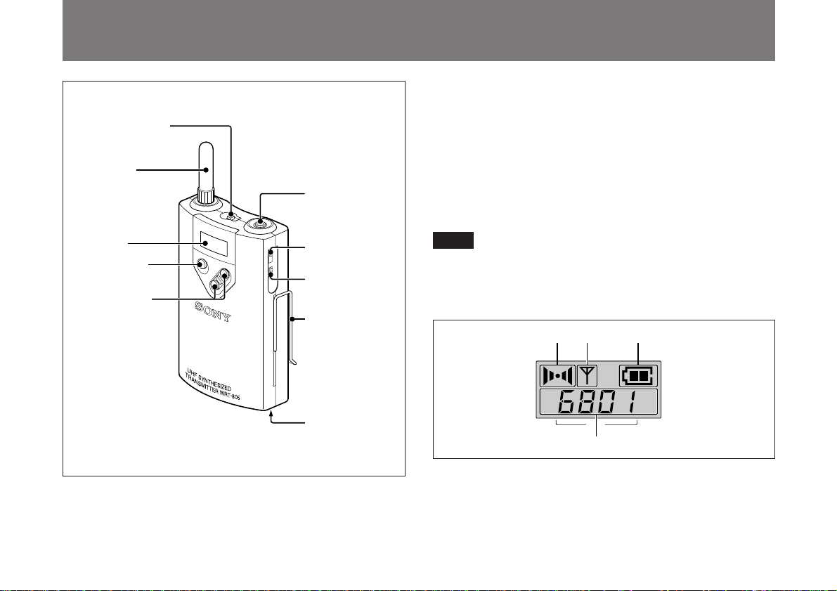
Parts Identification
1 POWER switch
Antenna
OFF
POWER
ON
2 Liquid-crystal
display
3 SET button
4 +/– buttons
AF
RF
BATT
CH
SET
+
–
INPUTPHASE
5 Audio input
connector
6 INPUT level
switch
7 PHASE switch
8 Belt clip
Battery
compartment
(See page 9.)
1 POWER switch
Turns the power of the transmitter ON or OFF.
When you set this switch to ON without holding any other
button, the transmitter is set to normal Transmit mode and
transmits the signal of the selected channel.
When you set this switch to ON while holding the SET
button down, Setting mode is initiated. No signal is
transmitted in Setting mode.
For setting mode, see “Settings” on page 12.
Note
Be sure to connect a microphone or guitar cable before
turning the power ON.
2 Liquid-crystal display
Location of parts
a AF (audio input) indication
Lights when an audio signal over the reference level is being
supplied.
7
Page 8
Parts Identification
b RF (antenna output) indication
Lights when a signal is being transmitted from the antenna.
c BATT (battery) indication
Displays the status of the battery.
See “Battery indication” on page 10.
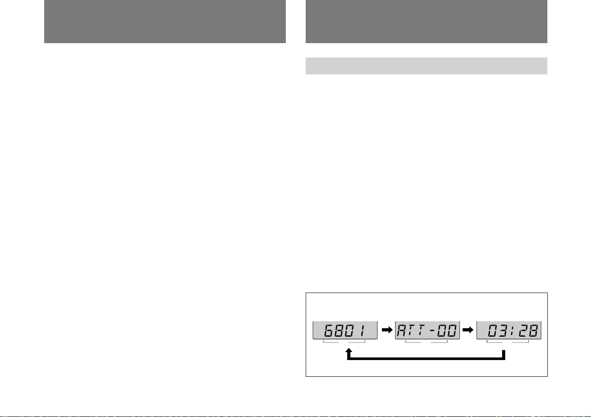
d CH (channel) indication
Displays the transmission channel.
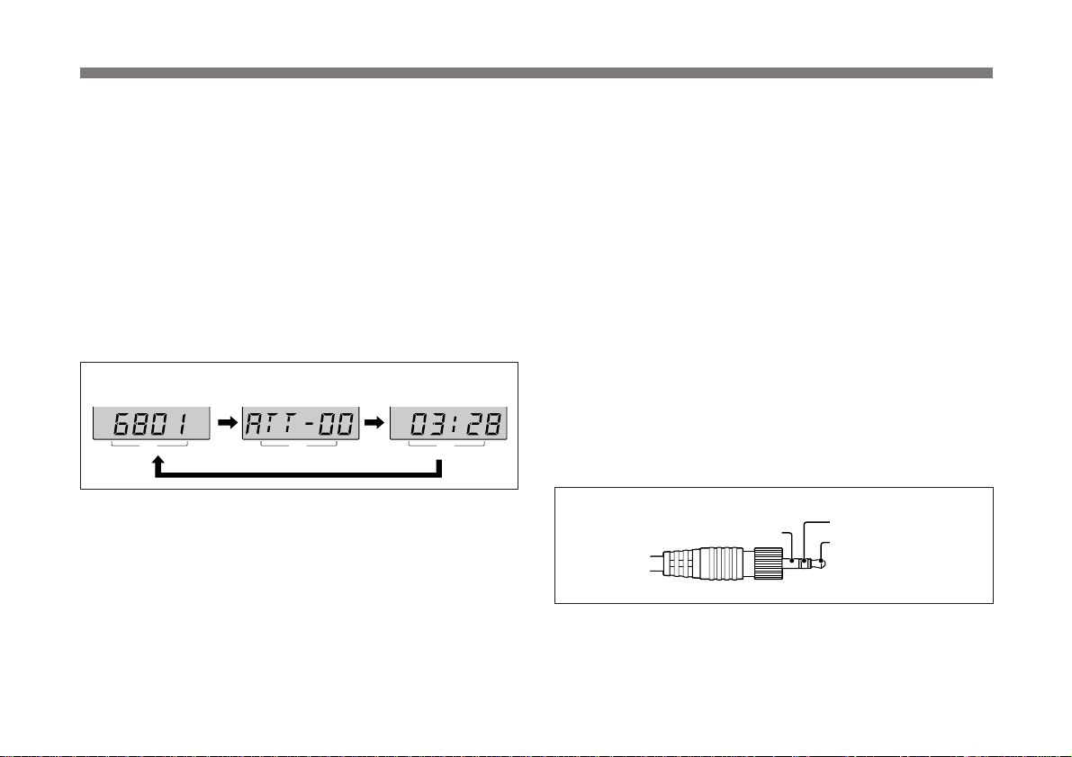
Each time you press the SET button in normal Transmit
mode, the channel indication changes to the input
attenuation and accumulated time indications.
Channel
indication
CH CH CH
Attenuation
indication
Accumulated time
indication
In Attenuation indication mode, it displays the input
attenuation setting in dB, which can be changed in a range
of 0 to 21 dB in 3-dB steps.
In Accumulated time indication mode, it displays the
accumulated time of battery use (in 1-minute increments).
For adjustments, see “Changing the Channel Selection” on
page 13, “Changing the Input Attenuation Setting” on page
14 or “Resetting the Accumulated Time Indication” on page
15.
3 SET button
In normal transmit mode, press this button to change the
indication items in the lower half of the liquid-crystal
display.
When you set the POWER switch to ON while holding this
button down, setting mode is initiated. In Setting mode,
press this button to select the item to be set.
For Setting mode, see “Settings” on page 12.
4 + (+ selection) / – (– selection/reset) buttons
In setting mode, select the transmission channel and
attenuator level using either of these buttons, or reset the
accumulated time indication to “00:00” with the – button.
For Setting mode, see “Settings” on page 12.
5 Audio input connector (ø3.5 mm, with locking
mechanism)
To connect a microphone or other audio source.
GND
+5 V (output)
INPUT
See “Connections” on page 11.
8
Page 9
SET
CH
+
–
PUSH
6 INPUT level switch
Select the reference input level appropriate for the connected
audio source.
–60 dBV: For a microphone
–40 dBV: For an electric guitar
7 PHASE switch
Select the input phase appropriate for the connected audio
source.
= : For a microphone other than the ECM-44BMP or an
electric guitar
ø : For the ECM-44BMP
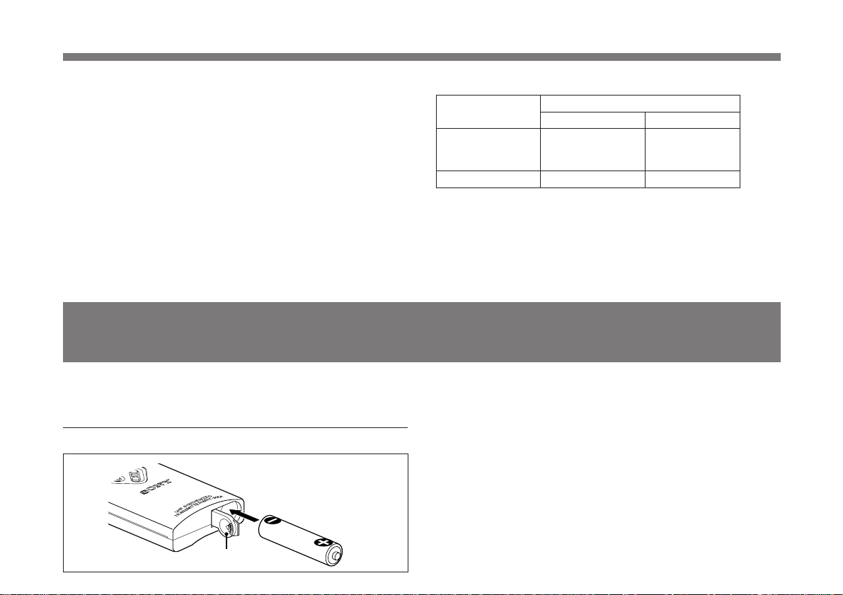
Power Supply
Switch functions
7 hctiwsESAHP
=
øPMB44-MCE—
6 hctiwslevelTUPNI
VBd06–VBd04–
PMB121-MCE
PMB221-MCE
PMB013-MCE
PM7.0-CG
8 Belt clip
You can easily carry the transmitter attached to your
clothing on your belt, etc. Depending on your selection of
the mount holes for the belt clip, you can adjust the position
or even carry the unit with the antenna downward.
The transmitter can operate on one LR6 (size AA) alkaline
battery continuously for about 6 hours at 25°C (77°F).
Inserting the battery
1 Slide the lid in the direction of the arrow (
battery compartment.
2 Match the polarities and insert the battery.
) to open the
$
3 Close the lid and slide it in the reverse direction to lock.
Lid
9
Page 10
Power Supply
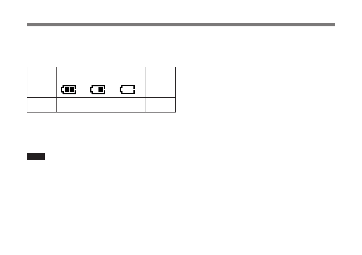
Battery indication
When you turn the power on, the battery status appears in
the BATT indication on the liquid-crystal display.
1234
TTAB
noitacidni
yrettaB
noitidnoc
sthgiLsthgiLsehsalFffoseoG
dooG
nahtsseL
egrahc-flah
tsomlA
detsuahxe
detsuahxe
When the battery reaches stage 3 shown in the table, the
BATT indication on the WRR-800A/801A/850A also starts
flashing.
Promptly replace the battery when the indications flash.
Note
The indication may be incorrect if the battery is not new
when inserted. If you plan to use the transmitter for a long
period, it is best to replace the battery with new one.
Notes on battery
Use a new alkaline battery.
•
Be careful to insert the battery with the correct polarity.
•
When not using the transmitter for a long period, remove the
•
battery to avoid leakage. If the battery does leak, clean all
leakage from the unit and insert a new battery. Leakage left
in the unit may cause poor battery contact. If there seems to
be poor battery contact, consult your Sony dealer.
yletelpmoC
10
Page 11
Connections
Caution
When connecting a microphone or electric guitar to the unit,
be sure to turn the unit off.
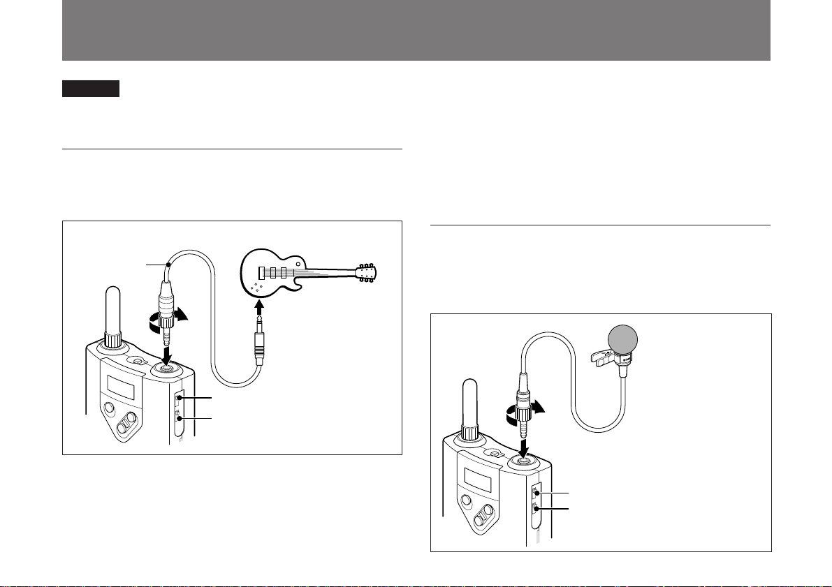
To connect an electric guitar
For connection of an electric guitar, use the optional GC-0.7
MP Guitar Cable.
GC-0.7 MP
guitar cable
(optional)
2
OFF
POWER
1
ON
AF
RF
BATT
CH
SET
+
–
INPUT level switch: –40 dBV
INPUTPHASE
PHASE switch: =
To obtain the proper output level
The optimum level setting depends on type of guitar. Set the
INPUT level switch and the ATT (attenuator) level of this unit
according to the guitar to be used.
Loud noise: If noise is not negligible even if the INPUT
switch is set at “–40 dBV” and the ATT level is “0 dB,” set
the INPUT switch to “–60 dBV” and adjust the ATT level
for an optimum result.
Distortion: If the guitar sound is distorted even if the
INPUT switch is set at “–40 dBV” and the ATT level is “0
dB,” increase the ATT level by 3 dB (0 to 3 to 6 . . . 21 dB).
For the ATT level adjustment, see page 13.
To connect a microphone
When using one of the following optional Sony Electret
Condenser Microphones equipped with a miniature phone
plug, connect it as illustrated below.
Sony
Electret Condenser
Microphones (optional):
ECM-44BMP
ECM-122BMP
2
OFF
POWER
1
ON
AF
RF
BATT
CH
SET
+
–
INPUT switch: –60 dBV
INPUTPHASE
Set the PHASE switch to “ø” when
using the ECM-44BMP.
For other microphone, set it to “=.”
ECM-121BMP
ECM-310BMP
11
Page 12
CH CH CH
Notes on Microphone
System Operation
To operate with 2 or more channels, maintain a distance of
•
at least 30 cm (1 ft.) between each pair of transmitters.
For details of operation with 2 or more channels, refer to
the Operating Instructions for the WRR-800A/801A UHF
Synthesized Diversity Tuners.
Ensure that the tuners set to channels not being used are
•
either turned off or set to the minimum output level.
When powering the transmitter on or off, to keep the noise
•
to a minimum, set the audio output level from the tuner or
mixer to a minimum.
Powering the transmitter on without checking the channel
•
selection first may interfere with the operation of other
microphones/transmitters, if the current setting is already
being used.
Separate the reception antennas and the transmitter by more
•
than 3 meters (10 ft.).
Settings
Initiating Setting Mode
In Setting mode, you can change the transmission channel
and the attenuation level, or reset the accumulated time
indication.
To enter Setting mode
While holding down the SET button, set the POWER switch
to ON.
Hold the SET button down until a display appears on the
liquid-crystal display.
The transmitter enters Setting mode and the indication
before the transmitter was previously turned OFF flashes on
the liquid-crystal display.
Each time you press the SET button, Channel selection
mode, Attenuator adjustment mode (page 14) and
Accumulated time indication reset mode (page 15) are
cyclically switched.
Channel selection
Attenuator
adjustment
Accumulated time
indication reset
12
Press the SET button.
Page 13
Changing the Channel Selection
1 Set the unit to Setting mode.
3 Once the desired channel number appears, set the
POWER switch to OFF to release Setting mode.
Or, press the SET button to continue operations in Setting
mode.
If the channel number is not displayed, press the SET
button to obtain the channel number indication.
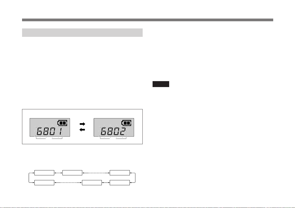
2 Press the + or – button to select the channel.
Pressing the + button cyclically changes the channel
indication in the order shown in the table of “Channels
and Carrier Frequencies” on page 6. Pressing the –
button changes it in reverse order.
AF RF BATT
CH
If you keep either button pressed, the channel setting will
be incremented or decremented successively.
The display will cycle from 68-01 through 69-47.
68-01 68-02 68-47
69-47 69-02 69-01
+ button
– button
AF RF BATT
CH
The next time you turn on the power only by setting the
POWER switch to ON, the transmitter will be set to
Transmit mode with the selected channel.
Notes
The unit cannot transmit in Setting mode.
•
Make sure that the channel selected is the same as that
•
selected on the tuner used in the same system.
Depending on the noise or interference conditions, the
•
selectable channels may not necessarily all be usable. If
necessary, you can determine the usable channels by
stepping the channel selection through a number of
channels on a tuner with the transmitter set to OFF. Those
channels on which the RF indicator of the tuner does not
light are usable.
If there is a TV broadcasting station near by, do not use
•
the station's channel.
The unit may not operate correctly if it is turned on again
•
immediately after turning off the power while in setting
mode. Pause for a few seconds or more before turning on
the power again.
13
Page 14
Settings
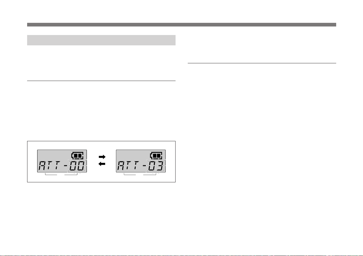
Changing the Input Attenuation Setting
You can change the input attenuation setting in 3-dB steps
in a range of 0 to 21 dB. You can change it either in Setting
mode or in Transmit mode.
Changing in Setting mode
1 Set the unit to Setting mode.
2 If the attenuation level is not displayed, press the SET
button to obtain the attenuation indication.
3 Press the + or – button to select the attenuation setting.
AF RF BATT
CH
If you keep either button pressed, the level will be
incremented or decremented successively.
+ button
– button
AF RF BATT
CH
4 Once the desired level appears, set the POWER switch to
OFF to release Setting mode.
Or, press the SET button to continue operations in Setting
mode.
The next time you turn on the power only by setting the
POWER switch to ON, the transmitter will be set to
Transmit mode with the selected attenuation setting.
Changing in Transmit mode
You can also change the input attenuation setting during
transmission.
1 If the attenuation level is not displayed, press the SET
button to obtain the attenuation indication.
2 Press the + or – button to select the attenuation setting.
14
Page 15
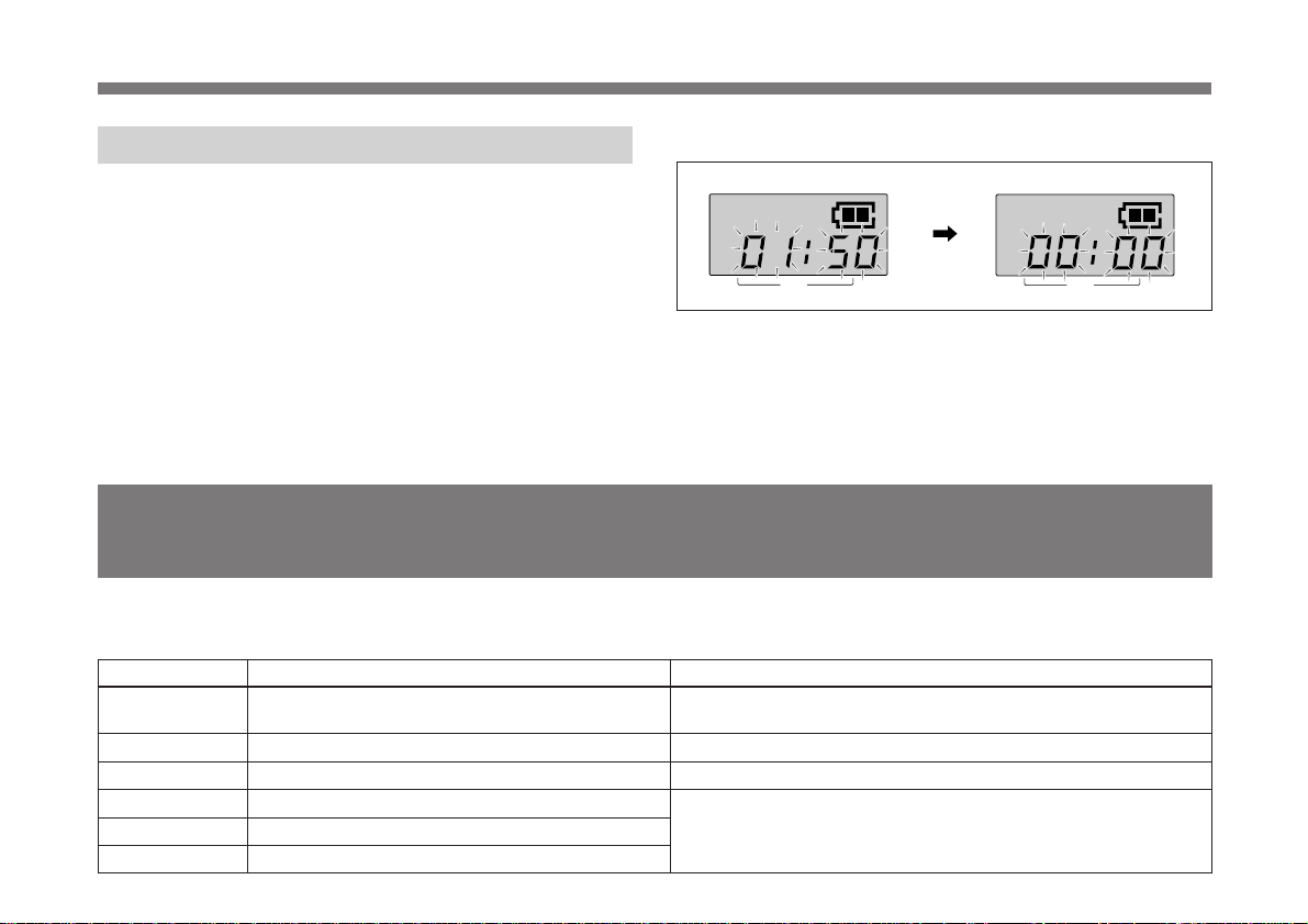
Resetting the Accumulated Time Indication
The time indication accumulates time in hours and minutes
when the WRT-805A is on.
Reset the indication to “00:00” whenever you replace the
battery so that it can display the running time of the battery.
The time indication resets to “00:00.”
AF RF BATT
– button
CH
AF RF BATT
CH
1 Set the unit to Setting mode.
2 If the accumulated time is not displayed, press the SET
button to obtain the accumulated time indication.
3 Press the – button.
Error Messages
When a problem occurs, one of the following error messages
may appear on the display.
segasseMstnetnoCserusaeM
11rorrE.atadyromempukcabniderruccororrenA
12rorrE.elbuortnisitiucricdezisehtnysLLPehT .relaedynoSruoytcatnoC
13rorrE.eulavelbawollaehtsdeecxeegatlovyrettabehT .yrettabdeificepsehtesU
14rorrEtiucriclanretninafotcefeD
16rorrEtiucriclanretninafotcefeD
While you see “00:00” indication, you can go back to
previous value by pressing the + button.
4 Set the POWER switch to OFF to release Setting mode.
dnalennahcgnittimsnartehtteS.dezilaitinisawatadehT
.niaganoitaunettatupnieht
.relaedynoSruoytcatnoC15rorrEtiucricretrevnocD/AehtfotcefeD
15
Page 16

Specifications
Transmitter and modulator section
Oscillator Crystal controlled PLL synthesizer
Type of emission 110KF3E
Carrier frequencies 794.125 to 805.875 MHz
(94 settings at 125 kHz intervals)
RF power output 10 mW
Frequency stability Within ±0.005%
Spurious radiation 20 nW or less
Tone signal 32.768 kHz
Type of antenna
1
/4 -wavelength helical
Audio section
Pre-emphasis 50 µs
Deviation ±16 kHz (–40 dBV
±5 kHz (–60 dBV
1)
, 1 kHz input)
1)
, 1 kHz input)
Maximum deviation ±40 kHz
Frequency response 70 to 15,000 Hz
Signal-to-noise ratio 57 dB or more
(A-weighted, modulation frequency
1 kHz, with reference deviation at
WRR-800A/801A)
Audio attenuator 0 to 21 dB, variable in 3-dB steps
Reference input level –60/–40 dBV
1)
at audio attenuator
0 dB
Power section
Power requirements 1.5 V DC
(one LR6/size AA alkaline battery)
Battery life Approx. 6 hours at 25°C or 77°F
with Sony LR6 alkaline battery
General
Operating temperature 0°C to +50°C (32°F to 122°F)
Storage temperature –30°C to +60°C (–22°F to +140°F)
Dimensions 58 × 95 × 21 mm (w/h/d)
(23/8 × 33/4 × 27/32 inches)
Mass Approx. 100 g (3.5 oz) including
battery
2)
2)
Supplied accessory
Operating Instructions (1)
Design and specifications are subject to change without
notice.
. . . . . . . . . . . . . . . . . . . . . . . . . . . . . . . . . . . . . . . . . . . . . . . . . . . . . . . . . . . . . . . . . . . . . . . . . . . . . . . . . . . . . . . . . . . . . . . . . . . . . . . . . . . . . . . . . . . . . . . . . . . . . . . . . . . . . . . . . . . . . . . . . . . . . . . . . . . . . . . . . . . . . . . . . .
1) 0 dBV = 1 Vrms
2) INPUT switch at –60 dBV position
16
Page 17

Español
Índice
Precauciones..................................................................... 17
Introducción ..................................................................... 18
Características .............................................................. 18
Canales y frecuencias portadoras .................................. 20
Identificación de partes ................................................... 21
Fuente de alimentación ................................................... 23
Conexiónes........................................................................ 25
Notas sobre el funcionamiento del sistema
de micrófono ............................................................... 26
Precauciones
La unidad ha sido diseñada para emplearse a una
•
temperatura ambiente de 0°C a 50°C (32°F a 122°F).
No coloque la unidad en o cerca de fuentes de calor tales
•
como lámparas o amplificadores de potencia, o un lugar
expuesto a los rayos del sol o a humedad excesiva. Estos
lugares pueden afectar la terminación exterior o las piezas
en el interior de la unidad.
Si se utiliza la unidad en lugares muy húmedos o con
•
mucho polvo o si se coloca en un lugar expuesto al gas,
limpie bien su superficie y los conectores con un paño
seco y suave, después del uso. Un uso prolongado de la
unidad en dichos lugares, o si no la limpia después de
utilizarla en tales lugares, puede acortar su longevidad.
Ajustes .............................................................................. 26
Activación del modo de ajuste..................................... 26
Cambio de la selección de canal .................................. 27
Cambio del ajuste de atenuación de entrada ................ 28
Reposición de la indicación de tiempo acumulado de
utilización..................................................................... 29
Mensajes de error ............................................................ 30
Especificaciones ............................................................... 31
Cuando limpie la unidad, no utilice solventes orgánicos
•
tales como diluyentes o bencina que puedan dañar el
acabado de la unidad.
La unidad ha sido ajustada precisamente en fábrica. No
•
debe tocar o tratar de reparar sus piezas interiores.
17
E
Español
Page 18

Introducción
El WRT-805A es un transmisor para utilizarse en
combinación con el sintonizador de recepción en diversidad
sintetizado de UHF WRR-800A/801A para un sistema de
micrófono inalámbrico sintetizado de UHF de 800 MHz
para fines de producción de programas de radiodifusión o de
películas.
El WRT-805A también puede utilizarse en un sistema de
micrófono inalámbrico Sony convencional compuesto por el
transmisor sintetizado de UHF WRT-810A/820A, el
sintonizador de recepción en diversidad sintetizado de UHF
WRR-810A/820A/840A/850A, etc.
El micrófono/transmisor y los sintonizadores del sistema de
micrófono inalámbrico se clasifican por la banda de
frecuencias.
Una banda de frecuencias de 12 MHz (o dos canales de
televisión de número consecutivo, como el 68 y el 69 del
WRT-805A) está asignada a cada modelo de micrófono/
transmisor y sintonizador.
Para componer un sistema de micrófono inalámbrico de
UHF, cerciórese de combinar un micrófono/transmisor y un
sintonizador que posean el mismo número de canal de TV.
Características
Selección fácil de 94 canales
La unidad puede funcionar con cualquiera de 94 frecuencias
portadoras seleccionadas mediante una sencilla operación de
teclas.
Compacto y ligero
La innovadora tecnología de montaje de alta densidad ha
permitido la creación de este transmisor compacto y ligero,
que le permitirá moverse a cualquier parte para la
recopilación electrónica de noticias (ENG) y la producción
electrónica en el sitio (EFP).
El diseño curvado de la caja moldeada le permitirá adaptarlo
cómodamente a su cintura.
Información sobre el estado de la pila
Este transmisor posee la capacidad de poder transmitir
“información sobre el estado de la pila” al WRR-800A/
801A/850A para ofrecerle un aviso anticipado del
agotamiento de la pila.
Cuando el WRR-800A/801A/850A reciba la informción, el
LED y el visualizador de cristal líquido del panel
comenzarán a parpadear.
18
Page 19

Alimentación fácil con pila
El convertidor de CC-CC de gran eficacia incorporado
permite la operación estable, durante 6 horas continuas, con
una sola pila LR6 (tamaño AA).
Visualizador de cristal líquido para el control
coordinado de la operación
El visualizador de cristal líquido mostrará el número del
canal actual, la energía restante de la pila, el ajuste de la
atenuación de entrada, el nivel de entrada de AF, y la salida
de RF.
También existe una indicación de tiempo de operación
acumulado para poder controlar fácilmente la utilización de
la pila (en incrementos de 1 minuto).
Ajustes de canal almacenado y atenuación de entrada
La unidad conservará los ajustes de canal y de la atenuación
de entrada aunque desconecte su alimentación. Los ajustes
almacenados se conservará incluso aunque extraiga la pila.
Por lo tanto, cuando vuelva a utilizar la unidad, no
necesitará volver a realizar los mismos ajustes.
Atenuador electrónico de gran fiabilidad
El atenuador de nivel de entrada incorporado podrá ajustarse
dentro de un margen de 0 a 21 dB en pasos de 3 dB. Esto
reducirá la distorsión de la señal cuando se reciba una señal
de entrada de gran intensidad.
Portadora de RF con señal de tono
La unidad transmite la portadora de RF acompañada por una
señal de tono, lo que permitirá que el sintonizador, con su
circuito silenciador, elija solamente la señal de audio
pretendida.
Amplia gama dinámica y bajo ruido
El sistema compansor (compresor/expansor) permite la
transmisión en una amplia gama dinámica con el ruido
mínimo.
Conector de entrada de audio (3,5 mm de diámetro) con
mecanismo de bloqueo
El mecanismo de bloqueo de tipo tornillos asegura una
conexión fiable.
Antena helicoidal compacta
19
Page 20

Canales y frecuencias portadoras
El WRT-805A puede transmitir en cualquiera de los canales
inalámbricos indicadas a continuación.
lanaC
10-86521,49752-86521,79710-96521,00852-96521,308
20-86052,49762-86052,79720-96052,00862-96052,308
30-86573,49772-86573,79730-96573,00872-96573,308
40-86005,49782-86005,79740-96005,00882-96005,308
50-86526,49792-86526,79750-96526,00892-96526,308
60-86057,497 03-86057,797 60-96057,008 03-96057,308
70-86578,49713-86578,79770-96578,00813-96578,308
80-86000,59723-86000,89780-96000,10823-96000,408
90-86521,59733-86521,89790-96521,10833-96521,408
01-86052,597 43-86052,897 01-96052,108 43-96052,408
11-86573,59753-86573,89711-96573,10853-96573,408
21-86005,59763-86005,89721-96005,10863-96005,408
31-86526,59773-86526,89731-96526,10873-96526,408
41-86057,59783-86057,89741-96057,10883-96057,408
51-86578,59793-86578,89751-96578,10893-96578,408
61-86000,697 04-86000,997 61-96000,208 04-96000,508
71-86521,69714-86521,99771-96521,20814-96521,508
81-86052,69724-86052,99781-96052,20824-96052,508
91-86573,69734-86573,99791-96573,20834-96573,508
02-86005,697 44-86005,997 02-96005,208 44-96005,508
12-86526,69754-86526,99712-96526,20854-96526,508
22-86057,69764-86057,99722-96057,20864-96057,508
32-86578,69774-86578,99732-96578,20874-96578,508
42-86000,79742-96000,308
)zHM(aicneucerF
86VTedadnaB
lanaC
Con respecto a la selección del canal, consulte “Cambio de
la selección de canal” de la página 27.
)zHM(aicneucerF
86VTedadnaB
lanaC
)zHM(aicneucerF
96VTedadnaB
lanaC
)zHM(aicneucerF
96VTedadnaB
20
Page 21

Identificación de partes
1 Interruptor de
alimentación
(POWER)
Antena
5 Conector de
entrada de audio
6 Selector de nivel
INPUTPHASE
de entrada
(INPUT)
7 Selector de fase
(PHASE)
8 Presilla para el
cinturón
Compartimiento de
la pila
la página 23.)
2 Visualizador de
cristal líquido
3 Tecla de ajuste
(SET)
4 Teclas de
selección (+/–)
/reposición (–)
OFF
POWER
ON
AF
RF
BATT
CH
SET
+
–
Ubicación de partes
1 Interruptor de alimentación (POWER)
Utilícelo para conectar y desconectar la alimentación del
transmisor.
Cuando ponga este interruptor en ON sin mantener
presionada ninguna otra tecla, el transmisor pasará al modo
de transmisión normal, y transmitirá la señal del canal
seleccionado.
Cuando ponga este interruptor en ON manteniendo
presionada la tecla SET, se iniciará el modo de ajuste. En el
modo de ajuste no se transmitirá señal.
Con respecto al modo de ajuste, consulte “Ajustes” de la
página 26.
Nota
Cerciórese de conectar un micrófono o una guitarra antes de
conectar la alimentación.
2 Visualizador de cristal líquido
a b c
AF RF BATT
(Consulte
CH
d
a Indicación de entrada de audio (AF)
Aparecerá cuando se esté suministrando una señal de audio
de nivel superior al de referencia.
21
Page 22

Identificación de partes
b Indicación de salida de antena (RF)
Aparecerá cuando se esté transmitiendo una señal a través
de la antena.
c Indicación de la pila (BATT)
Mostrará el estado de la pila.
Consulte “Indicación de la pila” de la página 24.
d Indicación de canal (CH)
Mostrará el canal de transmisión.
Cada vez que presione la tecla SET en el modo de
transmisión normal, la indicación del canal cambiará a las
de atenuación de entrada y de tiempo acumulado de
utilización.
Indicación del
canal
CH CH CH
Atenuación de
entrada
Tiempo acumulado
de utilización
En el modo de indicación de atenuación, mostrará el
ajuste de atenuación de entrada en dB, que podrá cambiarse
dentro de un margen de 0 a 30 dB en pasos de 3 dB.
En el modo de indicación del tiempo acumulado de
utilización, mostrará el tiempo acumulado de utilización de
la pila (en incrementos de 1 minuto).
Con respecto a los ajustes, consulte “Cambio de la selección
de canal” de la página 27, “Cambio del ajuste de atenuación
de entrada” de la página 28, o “Reposición de la indicación
de tiempo acumulado de utilización ” de la página 29.
22
3 Tecla de ajuste (SET)
En el modo de transmisión normal, presione esta tecla para
cambiar los ítemes de indicación de la mitad inferior del
visualizador de cristal líquido.
Si pone el interruptor POWER en ON manteniendo
presionada esta tecla, se iniciará el modo de ajuste. En el
modo de ajuste, presione esta tecla para seleccionar el ítem
que desee ajustar.
Con respecto al modo de ajuste, consulte “Ajustes” de la
página 26.
4 Teclas de selección (+)/reposición (–)
En el modo de ajuste, seleccione el canal de transmisión y el
nivel de atenuación utilizando cualquiera de estas teclas, o
reponga la indicación de tiempo acumulado de utilización a
“00:00” con la tecla –.
Con respecto al modo de ajuste, consulte “Ajustes” de la
página 26.
5 Conector de entrada de audio (3,5 mm ø, con
mecanismo de bloqueo
Para conectar un micrófono u otra fuente de audio.
Masa
+5 V (salida)
Entrada
Consulte “Conexiones” de la página 25.
Page 23

SET
CH
+
–
PUSH
6 Selector de nivel de entrada (INPUT)
Seleccione el nivel de entrada de referencia para la fuente de
audio conectada.
–60 dBV: Para un micrófono
–40 dBV: Para una guitarra eléctrica
7 Selector de fase (PHASE)
Seleccione la fase de entrada apropiada para la fuente de
audio conectada.
= : Para un micrófono que no sea el ECM-44BMP o para
una guitarra eléctrica
ø :Para el ECM-44BMP
Fuente de alimentación
Funciones de los selectores
7 edrotceleS
)ESAHP(esaf
=
øPMB44-MCE—
6 levinedrotceleS
VBd06–VBd04–
PMB121-MCE
PMB221-MCE
PMB013-MCE
)TUPNI(adartneed
PM7.0-CG
8 Presilla para el cinturón
Usted podrá transportar fácilmente el transmisor fijado a su
cinturón, etc. Dependiendo de la selección de los orificios de
montaje de la presilla para el cinturón, podrá ajustar la
posición, o incluso llevar la unidad con la antena hacia abajo.
El transmisor podrá funcionar con una pila alcalina LR6
(tamaño AA) durante unas 6 horas a 25°C.
Inserción de la pila
Tapa
1 Deslice la tapa en el sentido de la flecha (
) para abrir el
$
compartimiento de la pila.
2 Haga coincidir los polos e inserte la pila.
3 Cierre la tapa y deslícela en sentido contrario para
bloquearla.
23
Page 24

Fuente de alimentación
Indicación de la pila
Cuando conecte la alimentación, en la indicación BATT del
visualizador aparecerá el estado de la pila.
12 34
nóicacidnI
TTAB
edodatsE
alipal
adidnecnEadidnecnEodnaedapraPadagapA
oneuB
edsoneM
eddatimal
agracal
-acitcárP
etnem
adatoga
etnem
adatoga
Cuando la pila llegue a la etapa 3 mostrada en la tabla, la
indicación BATT del WRR-800A/801A/850A comenzará a
parpadear.
Cuando parpadee esta indicación, reemplace la pila lo antes
posible.
Nota
La indicación puede ser incorrecta si la pila insertada no es
nueva. Cuando planee utilizar el transmisor durante mucho
tiempo, lo mejor será que reemplace la pila por otra nueva.
Notas sobre la pila
Utilice una pila alcalina nueva.
•
Tenga cuidado de insertar la pila con la polaridad correcta.
•
Cuando no vaya a utilizar el transmisor durante mucho
•
tiempo, extraiga la pila para evitar la fuga del electrólito
de la misma. Si se fuga, limpie bien la unidad e inserte
una pila nueva.
-atelpmoC
Si dejase electrólito en la unidad, podría provocar el mal
contacto de la pila. Cuando parezca que la pila no hace
buen contacto, consulte a su proveedor Sony.
24
Page 25

Conexiones
Precaución
Antes de conectar un micrófono o una guitarra eléctrica a la
unidad, cerciórese de desconectar la alimentación de dicha
unidad.
Para conectar una guitarra eléctrica
Para conectar una guitarra eléctrica, utilice un cable para
guitarra GC-0.7 MP opcional.
Cable para guitarra
GC-0.7 MP (opcional)
2
OFF
POWER
1
ON
AF
RF
BATT
CH
SET
+
–
Selector de nivel INPUT: –40 dBV
INPUTPHASE
Selector PHASE: =
Para obtener el nivel de salida apropiado
El ajuste óptimo del nivel dependerá del tipo de guitarra.
Ajuste el selector de nivel INPUT y el de atenuación (ATT)
de esta unidad de acuerdo con la guitarra que esté utilizando.
Ruido bajo: Si el ruido no es insignificante aunque el
selector INPUT esté en “-40 dBV”, y el selector ATT esté
ajustado a “0 dB”, ajuste el selector INPUT a “-60 dBV”, y
el selector LEVEL hasta obtener el óptimo resultado.
Distorsión: Si el sonido de la guitarra se oye distorsionado
aunque el selector INPUT esté ajustado a “0 dB”, aumente
el nivel de atenuación 3 dB (0 a 3, 6 ... 21 dB).
Con respecto al ajuste del nivel de atenuación, consulte la
página 28.
Para conectar un micrófono
Cuando utilice uno de los siguientes micrófonos
electrostáticos de electreto Sony opcionales provistos de
miniclavija telefónica, conéctelo como se muestra en la
figura siguiente.
Micrófonos
electrostáticos de
electreto Sony:
ECM-44BMP
ECM-122BMP
2
OFF
POWER
1
ON
AF
RF
BATT
CH
SET
+
–
Selector de nivel INPUT: –60 dBV
INPUTPHASE
Cuando utilice el ECM-44BMP, ponga
el selector PHASE en “ø”.
Para otro micrófono, póngalo en “=”.
ECM-121BMP
ECM-310BMP
25
Page 26

CH CH CH
Notas sobre el funcionamiento
del sistema de micrófono
Para operar con 2 o más canales, mantenga una distancia
•
de por lo menos 30 cm (1 pie) entre cada par de
transmisores.
Con respecto a la operación con 2 o más canales,
consulte el manual de instrucciones de los sintonizadores
de recepción en diversidad sintetizados de UHF WRR800A/801A.
Confirme que los sintonizadores ajustados a canales que
•
no se están usando se han desconectado o están en su
nivel de salida mínimo.
Cuando conecte o desconecte el transmisor, para mantener
•
el ruido a un mínimo, ajuste el nivel de salida de audio del
sintonizador o mezclador al mínimo.
La conexión de la alimentación del transmisor sin haber
•
verificado primero la selección de canal puede interferir
con el funcionamiento de otros micrófonos/transmisores,
si ya se estaba utilizando la misma selección para otro
uso.
Separe las antenas de recepción y el transmisor más de 3
•
metros (10 pies).
Ajustes
Activación del modo de ajuste
En el modo de ajuste usted podrá cambiar el canal de
transmisión y el nivel de atenuación, o reponer la indicación
de tiempo acumulado de utilización.
Para entrar en el modo de ajuste
Manteniendo presionada la tecla SET, ponga el interruptor
POWER en ON.
Mantenga presionada la tecla SET hasta que en el
visualizador de cristal líquido aparezca una indicación.
El transmisor entrará en el modo de ajuste y en el
visualizador de cristal líquido parpadeará la indicación
existente antes de haber desconectado (OFF) la alimentación
del transmisor.
Cada vez que presione la tecla SET, cambiarán cíclicamente
el modo de selección de canal, el modo de ajuste de
atenuación (página 28), y el modo de reposición de la
indicación de tiempo acumulado de utilización (página 29).
Selección de
canal
Ajuste de
atenuación
Reposición de la
indicación de tiempo
acumulado
26
Presione la tecla SET.
Page 27

Cambio de la selección de canal
1 Ponga la unidad en el modo de ajuste.
Si no está visualizándose el número de canal, presione la
tecla SET para hacer que se visualice.
2 Presione la tecla + o – para seleccionar el canal.
Al presionar la tecla +, la indicación de canal cambiará
cíclicamente en el orden mostrado en la tabla “Canales y
frecuencias portadoras” (página 20).
AF RF BATT
CH
Si mantiene presionada cualquiera de las teclas, el ajuste
del canal aumentará o se reducirá sucesivamente.
La visualización cambiará cíclicamente de 68-01 a 69-47.
68-01 68-02 68-47
69-47 69-02 69-01
Tecla +
Tecla –
AF RF BATT
CH
3 Después de haber aparecido el número de canal deseado,
ponga el interruptor POWER en OFF para desactivar el
modo de ajuste.
O, presione la tecla SET para continuar la operación en el
modo de ajuste.
La próxima vez que conecte la alimentación poniendo
solamente el interruptor POWER en ON, el transmisor se
ajustará al modo de transmisión con el canal
seleccionado.
Notas
La unidad no podrá transmitir en el modo de ajuste.
•
Cerciórese de que el canal seleccionado sea el mismo que
•
el elegido en el sintonizador utilizado en el mismo
sistema.
Dependiendo de las condiciones de ruido o de interferencias,
•
es posible que no puedan utilizarse todos los canales
seleccionables. Si es necesario, podrá determinar los canales
utilizables probando varios canales en el sintonizador con la
alimentación del transmisor desconectada. Los canales en
los que el indicador de RF del sintonizador no se encienda
serán los que podrán utilizarse.
Si hay una emisora de televisión cercana, no utilice el
•
canal de la misma.
Es posible que la unidad no funcione correctamente si
•
conecta su alimentación inmediatamente después de
haberla desconectado estando en el modo de ajuste.
Espere algunos segundos antes de volver a conectar la
alimentación.
27
Page 28

Ajustes
Cambio del ajuste de atenuación de entrada
Usted podrá cambiar el ajuste de la atenuación de entrada en
pasos de 3 dB dentro de un margen de 0 a 21 dB. Usted
podrá realizar el ajuste en el mode de ajuste o en el de
transmisión.
Cambio en el mode de ajuste
1 Ponga la unidad en el modo de ajuste.
2 Si no se visualiza el nivel de ajuste, presione la tecla SET
para obtener la indicación de atenuación.
3 Presione la tecla + o – para seleccionar el ajuste de atenuación.
AF RF BATT
CH
Si mantiene presionada cualquiera de las teclas, el ajuste
del canal aumentará o se reducirá sucesivamente.
Tecla +
Tecla –
AF RF BATT
CH
4 Después de haber aparecido el nivel deseado, ponga el
interruptor POWER en OFF para desactivar el modo de
ajuste. O, presione la tecla SET para continuar la
operación en el modo de ajuste.
La próxima vez que conecte la alimentación poniendo
solamente el interruptor POWER en ON, el transmisor se
ajustará al modo de atenuación seleccionado.
Cambio en el mode de transmisión
Usted también podrá ajustar el nivel de entrada de
atenuación durabte la transmision.
1 Si no se visualiza el nivel de ajuste, presione la tecla SET
para obtener la indicación de atenuación.
2 Presione la tecla + o – para seleccionar el ajuste de atenuación.
28
Page 29

Reposición de la indicación de tiempo
acumulado de utilización
La indicación de tiempo acumulará las horas y minutos de
utilización cuando conecte la alimentación del WRT-805A.
Reponga la indicación a “00:00” cada vez que reemplace la
pila a fin de que visualice el tiempo de utilización de la misma.
1 Ponga la unidad en el modo de ajuste.
2 Si el tiempo acumulado de utilización no se visualiza,
presione la tecla SET para obtener la indicación del
tiempo acumulado de utilización.
3 Presione la tecla –.
La indicación se repondrá a “00:00”.
AF RF BATT
Tecla –
CH
Mientras esté viendo la indicación “00:00”, podrá volver
al valor anterior presionando la tecla +.
AF RF BATT
CH
4 Para desactivar el modo de ajuste, ponga el interruptor
POWER en OFF.
29
Page 30

Mensajes de error
Cuando ocurra un problema, es posible que en el
visualizador aparezca uno de los mensajes de error
siguientes.
sejasneModinetnoCsadideM
11rorrE
12rorrE
13rorrE.elbisimreprolavleasaperbosalipalednóisnetaL .adacificepsealipalecilitU
14rorrE.onretniotiucricnuneotcefeD
16rorrE.onretniotiucricnuneotcefeD
.odlapseredairomem
.odairevaátse
aledsotadsolnerorrenuodicudorpaheS
esafedehcnagneedelcubedodazitetnisotiucriclE
.adartneednóicaunetaalynóisimsnart
edlanacleratsujaaavleuV.odazilaicininahessotadsoL
.ynoSrodeevorpusnocotcatnocneesagnóP
.ynoSrodeevorpusnocotcatnocneesagnóP15rorrE.D/AroditrevnocledotiucricleneotcefeD
30
Page 31

Especificaciones
Sección del transmisor y modulador
Oscilador Sintetizador de PLL controlado por
cristal
Tipo de transmisión 110KF3E
Frecuencias portadoras 794,125 a 805,875 MHz
(94 ajustes a intervalos de
125 kHz)
Salida de potencia RF 10 mW
Estabilidad de la frecuencia
Dentro de ±0,005%
Radiación espuria 20 nW o menos
Señal de tono 32,768 kHz
Tipo de antena Helicoidal de 1/4 de longitud de
onda
Sección de audio
Preacentuación 50 µs
Desviación ±16 kHz
(–40 dBV 1), entrada de 1 kHz)
2)
±5 kHz
(–60 dBV 1), entrada de 1 kHz)
2)
Desviación máxima ±40 kHz
Respuesta de frecuencia 70 Hz a 15 kHz
Relación señal/ruido Más de 57 dB (ponderación A, con
desviación de referencia en WRR-
800A/801A)
Atenuador de audio 0 a 21 dB, variable en pasos de
3 dB
Nivel de entrada de referencia
–60/–40 dBV
1)
con el atenuador de
audio a 0 dB
Sección de alimentación
Alimentación 1,5 V CC (una pila alcalina LR6/
tamaño AA)
Duración de la pila Aprox. 6 horas a 25°C o 77°F (con
pila alcalina Sony LR6)
Generalidades
Temperatura de funcionamiento
0°C a +50°C (32°F a 122°F)
Temperatura de almacenamiento
–30°C a +60°C (–22°F a +140°F)
Dimensiones 58 × 95× 21mm (an/al/prf)
(23/8 × 33/4 × 27/32 pulg.)
Masa Aprox. 100 g incluyendo la pila
Accesorio suministrado
Manual de instrucciones (1)
El diseño y las especificaciones están sujetos a cambios sin
previo aviso.
.. . . . . . . . . . . . . . . . . . . . . . . . . . . . . . . . . . . . . . . . . . . . . . . . . . . . . . . . . . . . . . . . . . . . . . . . . . . . . . . . . . . . . . . . . . . . . . . . . . . . . . . . . . . . . . . . . . . . . . . . . . . . . . . . . . . . . . . . . . . . . . . . . . . . . . . . . . . . . . . . . . . . . . . . . .
1) 0 dBV = 1 Vrms
2) Selector INPUT ajustado a la posición –60 dBV
31
Page 32

Français
Avis pour les clients au Canada:
L’usage des appareils sans-fil Sony est réglé par l’Industrie
Canada comme décrit dans leur Cahier des Normes
Radioélectriques CNR-123. Une licence est normalement
requise. Le bureau de l’Industrie Canada doit être contacté.
Lorsque l’opération de l’appareil est dans les limites de la
bande de radiodiffusion, la licence est émanée sur la base
de non-interférence, non-protection avec les signaux de
radiodiffusion.
32
Page 33

Table des matières
Précautions....................................................................... 33
Introduction ..................................................................... 34
Caractéristiques............................................................ 34
Canaux et fréquences porteuses ..................................... 36
Identification des pièces .................................................. 37
Alimentation..................................................................... 39
Connexions ....................................................................... 41
Remarques sur le fonctionnement du système de
microphone ................................................................. 42
Précautions
Cet appareil est conçu pour utilisation à une température
•
ambiante de 0 à 50 °C.
Ne pas placer cet appareil sur ou près des sources de
•
chaleur comme l’équipement d’éclairage ou les
amplificateurs, ou dans un endroit exposé au soleil ou à
une humidité excessive, au risque d’endommager la
finition extérieure ou les composants internes de
l’appareil.
Réglages ............................................................................ 42
Amorçage du mode de réglage .................................... 42
Changement de sélection de canaux ............................ 43
Changement de réglage d’atténuation d’entrée ........... 44
Remise à zéro de l’indication de temps accumulé ....... 45
Messages d’erreur ........................................................... 45
Fiche technique ................................................................ 46
Si l’appareil est utilisé dans des endroits très humides ou
•
poussiéreux, ou en présence d’un gaz actif, en nettoyer la
surface et les connecteurs avec un linge propre et doux
immédiatement après utilisation sans quoi sa durée utile
pourrait être écourtée.
Ne jamais utiliser de dissolvant organique tel que du
•
diluant ou du benzène pour le nettoyage, au risque
d’endommager la finition de l’appareil.
L’ajustement de cet appareil est très précis. Ne pas
•
modifier les composants internes ni essayer de les réparer.
F
Français
33
Page 34

Introduction
L’émetteur WRT-805A s’utilise en conjonction avec le
syntoniseur de diversité synthétisé UHF WRR-800A/801A
pour un système de microphone UHF sans fil synthétisé à
bande 800 MHz à des fins de diffusion ou de production
cinématographique.
Le WRT-805A peut aussi être utilisé dans un système
conventionnel de microphone sans fil Sony composé de
l’émetteur synthétisé UHF WRT-810A/820A, du
syntoniseur de diversité synthétisé UHF WRR-810A/820A/
840A/850A, etc.
Le microphone/émetteur et les syntoniseurs du système de
microphone sans fil sont classifiés par bande de fréquence.
Une bande de fréquence de 12 MHz (ou deux canaux de
télévision à numéro consécutif, tel que 68 et 69 du WRT805A) est assignée à chaque modèle de microphone/
émetteur et syntoniseur. En élaborant un système de
microphone UHF sans fil, s’assurer de combiner un
microphone/émetteur et un syntoniseur ayant le même
numéro de canal de télévision.
Caractéristiques
Sélection facile de 94 canaux
La sélection de n’importe quelle des 94 fréquences porteuses
se fait en manipulant simplement un bouton.
Appareil léger et compact
La technologie novatrice de montage à haute densité a
permis de réaliser cet émetteur léger et compact assurant une
grande mobilité pour le journalisme électronique et la
production électronique sur place. La forme incurvée du
boîtier moulé s’adapte bien à la taille.
Indicateur d’état de la pile
Cet émetteur peut transmettre l’information d’état de la pile
au WRR-800A/801A/850A pour vous signaler d’avance que
la pile devra bientôt être remplacée.
L’information est envoyée au WRR-800A/801A/850A
environ une heure avant que la pile soit complètement à plat
pour pouvoir ainsi remplacer la pile du émetteur en toute
sécurité.
Quand le WRR-800A/801A/850A reçoit l’information, les
DEL de l’affichage ACL commencent à clignoter.
Alimentation sur pile ordinaire
Le convertisseur intégré C.C.-C.C. à haute efficacité permet
d’obtenir environ 6 heures de fonctionnement continu à
l’aide d’une seule pile alcaline LR6 (format AA).
34
Page 35

ACL pour la coordination des opérations
L’affichage à cristaux liquides ACL donne le numéro de
canal sélectionné, la puissance résiduelle de la pile, le
réglage d’atténuation d’entrée, le niveau d’entrée AF et la
sortie RF.
Un indicateur intégré permet de déterminer à vue le nombre
d’heures d’utilisation de la pile (par tranches d’une minute).
Sauvegarde des réglages de canal et d’atténuation
d’entrée
À la mise hors circuit, l’appareil garde en mémoire les
réglages de canal et d’atténuation d’entrée. Les réglages sont
sauvegardés même si l’on retire la pile. Il n’est donc pas
nécessaire de refaire les mêmes réglages lors de la prochaine
utilisation.
Atténuateur électronique ultra-fiable
L’atténuateur de niveau d’entrée intégré se règle sur une
gamme de 0 à 21 dB, par tranches de 3 dB. Il réduit la
distorsion du signal lorsqu’un signal audio excessivement
fort est capté.
Porteuse RF avec signal de tonalité
L’appareil transmet la fréquence porteuse RF accompagnée
d’un signal à tonalité, permettant au syntoniseur à circuit
silencieux de capter uniquement le signal audio ciblé.
Large gamme dynamique et faible bruit
Le système à compresseur/extenseur (compander) permet la
transmission sur une large gamme dynamique, avec un
minimum de bruit.
Connecteur d’entrée audio de 3,5 mm de diamètre à
mécanisme de blocage
Le mécanisme de blocage à visser assure la fiabilité du
raccordement.
Antenne hélicoïdale compacte
35
Page 36

Canaux et fréquences porteuses
Le WRT-805A peut transmettre sur n’importe quel canal
sélectionné de la liste ci-dessous.
lanaC
10-86521,49752-86521,79710-96521,00852-96521,308
20-86052,49762-86052,79720-96052,00862-96052,308
30-86573,49772-86573,79730-96573,00872-96573,308
40-86005,49782-86005,79740-96005,00882-96005,308
50-86526,49792-86526,79750-96526,00892-96526,308
60-86057,497 03-86057,797 60-96057,008 03-96057,308
70-86578,49713-86578,79770-96578,00813-96578,308
80-86000,59723-86000,89780-96000,10823-96000,408
90-86521,59733-86521,89790-96521,10833-96521,408
01-86052,597 43-86052,897 01-96052,108 43-96052,408
11-86573,59753-86573,89711-96573,10853-96573,408
21-86005,59763-86005,89721-96005,10863-96005,408
31-86526,59773-86526,89731-96526,10873-96526,408
41-86057,59783-86057,89741-96057,10883-96057,408
51-86578,59793-86578,89751-96578,10893-96578,408
61-86000,697 04-86000,997 61-96000,208 04-96000,508
71-86521,69714-86521,99771-96521,20814-96521,508
81-86052,69724-86052,99781-96052,20824-96052,508
91-86573,69734-86573,99791-96573,20834-96573,508
02-86005,697 44-86005,997 02-96005,208 44-96005,508
12-86526,69754-86526,99712-96526,20854-96526,508
22-86057,69764-86057,99722-96057,20864-96057,508
32-86578,69774-86578,99732-96578,20874-96578,508
42-86000,79742-96000,308
)zHM(ecneuqérF
86élétednaB
lanaC
Pour la sélection des canaux, voir “Changement de
sélection de canaux” à la page 43.
)zHM(ecneuqérF
86élétednaB
lanaC
)zHM(ecneuqérF
96élétednaB
lanaC
)zHM(ecneuqérF
96élétednaB
36
Page 37

Identification des pièces
1 Interrupteur
Antenne
5 Connecteur
d’entrée audio
6 Commutateur de
INPUTPHASE
niveau d’entrée
“INPUT”
7 Commutateur
de PHASE
8 Pince de ceinture
Logement de pile
(voir page 39)
2 Affichage ACL
3 Bouton de
réglage
4 Boutons +/–
OFF
POWER
ON
AF
RF
BATT
CH
SET
+
–
1 Interrupteur
Régler l’interrupteur sur “ON” pour la mise en circuit.
Lorsqu’on règle l’interrupteur sur “ON” sans tenir d’autres
boutons, l’émetteur se règle en mode de transmission
normale et transmet le signal au canal sélectionné.
Si on règle l’interrupteur sur “ON” tout en appuyant sur le
bouton “SET”, on amorce le mode de réglage. Aucun signal
n’est transmis en mode de réglage.
Pour de plus amples renseignements, voir “Réglages” à la
page 42.
Nota
S’assurer de raccorder un câble de guitare ou de microphone
avant la mise en circuit.
2 Affichage ACL
a b c
AF RF BATT
CH
d
Emplacement des pièces
a Indication AF (entrée audio)
S’allume lorsqu’un signal audio au-dessus du niveau de
référence est fourni.
37
Page 38

Identification des pièces
b Indication RF (sortie d’antenne)
S’allume lorsqu’un signal est transmis de l’antenne.
c Indication BATT (pile)
Indique la puissance résiduelle de la pile.
Voir “Indication d’état de la pile” à la page 40.
d Indication “CH” (canal)
Affiche le canal de transmission.
Chaque fois qu’on appuie sur le bouton “SET” en mode de
transmission normale, l’indication de canal change pour
afficher l’indication d’atténuation et l’indication de temps
accumulé.
Indication de
canal
CH CH CH
Indication
d’atténuation
Indication de temps
accumulé
En mode d’indication d’atténuation, on peut voir le
réglage d’atténuation d’entrée en dB, pouvant être changé
dans une gamme de 0 à 21 dB par tranches de 3 dB.
En mode d’indication de temps accumulé, on peut voir le
nombre d’heures d’utilisation de la pile (par tranches de 1
minute).
Pour les réglages, voir “Changement de sélection de
canaux” à la page 43, “Changement de réglage d’atténuation d’entrée” à la page 44 ou “Remise à zéro de l’indication de temps accumulé” à la page 45.
38
3 Bouton “SET”
En mode de transmission normale, appuyer sur ce bouton
pour changer les articles de l’indication dans la moitié
inférieure de l’affichage ACL.
En réglant l’interrupteur sur “ON” tout en appuyant sur ce
bouton, le mode de réglage est amorcé. En mode de réglage,
appuyer sur ce bouton pour sélectionner l’article que l’on
désire régler.
Pour le mode de réglage, voir “Réglages” à la page 42.
4 Boutons + (sélection +) / – (sélection –/remise à
zéro)
En mode de réglage, sélectionner le canal de transmission et
le niveau d’atténuateur en utilisant l’un ou l’autre de ces
boutons, ou remettre à “00:00” l’indication de temps
accumulé en appuyant sur le bouton –.
Pour le mode de réglage, voir “Réglages” à la page 42.
5 Connecteur d’entrée audio (ø3,5 mm avec
mécanisme de blocage)
Pour raccorder un microphone ou une autre source audio.
MASSE
+5 V (sortie)
ENTRÉE
Voir “Connexions” à la page 41.
Page 39

6 Commutateur de niveau d’entrée “INPUT”
7 ruetatummoC
ESAHPed
6 ”TUPNI“eértne’duaevinedruetatummoC
VBd06–VBd04–
=
PMB121-MCE
PMB221-MCE
PMB013-MCE
PM7.0-CG
øPMB44-MCE—
SET
CH
+
–
PUSH
Choisir le niveau d’entrée de référence approprié selon la
source audio connectée.
–60 dBV: Pour un microphone
–40 dBV: Pour une guitare électrique
7 Commutateur de PHASE
Sélectionner la phase d’entrée appropriée selon la source
audio connectée.
=:Pour tout autre microphone qu’un ECM-44BMP ou une
guitare électrique
ø:Pour le microphone ECM-44BMP
Alimentation
Fonctions du commutateur
8 Pince de ceinture
L’émetteur se transporte facilement en le fixant à un
vêtement ou à la ceinture. Selon la position de montage
sélectionnée pour la pince de ceinture, la position de
l’appareil peut être ajustée ou on peut même le transporter
en orientant l’antenne vers le bas.
L’émetteur peut fonctionner de façon continue pendant
environ 6 heures à une température de 25 °C à l’aide d’une
pile alcaline LR6 (format AA).
Insertion de la pile
Couvercle
1 Glisser le couvercle dans le sens de la flèche (
) pour
$
ouvrir le compartiment à pile.
2 Insérer la pile en respectant la polarité indiquée.
3 Refermer le couvercle et le glisser dans l’autre sens pour
le bloquer en place.
39
Page 40

Alimentation
Indication d’état de la pile
Lors de la mise en circuit, l’indication “BATT” apparaît
dans l’affichage à cristaux liquides.
1234
noitacidnI
TTAB
aledtatÉ
elip
émullAémullAetongilCtnietÉ
eégrahC
éitiomÀ
eégrahc
àeuqserP
talp
Quand la pile atteint le niveau 3 indiqué dans le tableau cidessus, l’indication “BATT” du WRR-800A/801A/850A
commence aussi à clignoter.
Remplacer promptement la pile quand les indicateurs
clignotent.
Nota
L’indication peut être incorrecte si la pile n’était pas neuve
lorsqu’elle a été insérée dans l’appareil. Si l’on prévoit
utiliser l’émetteur pendant une longue période de temps, il
est toujours préférable de remplacer la pile par une neuve.
-etèlpmoC
talpàtnem
Remarques au sujet de la pile
Toujours utiliser une pile alcaline neuve.
•
Bien s’assurer de respecter la polarité indiquée.
•
Si l’émetteur ne va pas être utilisé pendant une longue
•
période de temps, en retirer la pile pour éviter les fuites.
S’il se produit une fuite, nettoyer soigneusement le
compartiment et insérer une pile neuve. Par suite d’une
fuite, il peut y avoir un mauvais contact avec la pile. Si le
contact semble mauvais, consulter un dépositaire Sony.
40
Page 41

Connexions
Avertissement
Lors du raccordement d’un microphone ou d’une guitare
électrique sur l’appareil, s’assurer de mettre l’appareil hors
circuit.
Raccordement d’une guitare électrique
Pour le raccordement d’une guitare électrique, utiliser le
câble de guitare GC-0.7 MP optionnel.
Câble de guitare
GC-0.7 MP
(optionnel)
2
OFF
POWER
1
ON
AF
RF
BATT
CH
SET
+
–
Commutateur de niveau d’entrée
INPUTPHASE
“INPUT” : –40 dBV
Commutateur de PHASE : =
Pour obtenir le niveau de sortie optimal
Le réglage optimal du niveau de sortie dépend du type de
guitare. Régler le commutateur de niveau d’entrée “INPUT”
et l’atténuateur “ATT” selon la guitare utilisée.
Niveau du bruit: Si le niveau du bruit est élevé même
lorsque le commutateur “INPUT” est réglé à “-40 dBV” et
l’atténuateur à “0 dB”, régler le commutateur à “-60 dBV”
et l’atténuateur “ATT” au niveau optimal.
Distorsion: Si le son de la guitare présente de la distorsion
même lorsque le commutateur “INPUT” est réglé à “-40
dBV” et l’atténuateur à “0 dB”, augmenter le niveau de
l’atténuateur de 3 dB (0 à 3 à 6 ... 21 dB).
Pour le réglage du niveau de l’atténuateur, voir page 44.
Raccordement d’un microphone
Pour utiliser un de ces microphones optionnels Sony à
condensateur électret avec une fiche phono miniature,
effectuer le raccordement de la façon illustrée ci-dessous.
Microphones à
condensateur électret
Sony:
ECM-44BMP
2
OFF
POWER
1
ON
AF
RF
BATT
CH
SET
+
–
Commutateur de niveau d’entrée
INPUTPHASE
“INPUT” : –60 dBV
Régler le commutateur de PHASE à “ø”
pour utiliser le ECM-44BMP.
Pour tout autre microphone, le régler à “=”.
ECM-122BMP
ECM-121BMP
ECM-310BMP
41
Page 42

Remarques sur le fonctionnement
du système de microphone
Pour le fonctionnement à deux ou plusieurs canaux,
•
maintenir une distance d’au moins 30 cm (1 pi) entre
chaque paire d’émetteurs.
Pour plus de détails sur le fonctionnement à deux canaux
ou plus, se référer aux instructions de fonctionnement des
syntoniseurs de diversité synthétisés UHF WRR-800A/
801A.
S’assurer que les syntoniseurs réglés sur les canaux non
•
utilisés sont hors circuit ou réglés au niveau de sortie
minimum.
Lors de la mise en/hors circuit de l’émetteur, pour
•
maintenir le niveau de bruit au minimum, régler en
position minimum le niveau de sortie audio du syntoniseur
ou du mixeur.
La mise en circuit de l’émetteur sans vérifier d’abord la
•
sélection des canaux peut causer une interférence avec le
fonctionnement des autres microphones/émetteurs, si le
réglage courant est déjà utilisé.
Maintenir une distance de plus de 3 mètres (10 pi) entre
•
les antennes de réception et l’émetteur.
.
Réglages
Amorçage du mode de réglage
En mode de réglage, on peut changer le canal de
transmission ou le niveau d’atténuation, ou encore remettre
à zéro l’indication de temps accumulé.
Pour entrer en mode de réglage
Tout en appuyant sur le bouton “SET”, régler l’interrupteur
sur “ON”.
Tenir le bouton “SET” jusqu’à ce que l’affichage apparaisse
sur l’écran ACL.
L’émetteur entre en mode de réglage et l’indication qui
apparaissait avant que l’émetteur ne soit mis hors circuit
clignote sur l’affichage ACL.
Chaque fois que l’on appuie sur le bouton “SET”, on passe
successivement en mode de sélection de canal, mode
d’ajustement d’atténuateur (page 44) et mode de remise à
zéro d’indication de temps accumulé (page 45).
Sélection de
canal
Ajustement
d’atténuateur
Remise à zéro de
l’indication de
temps accumulé
42
CH CH CH
Appuyer sur le bouton “SET”
Page 43

Changement de sélection de canaux
1 Amorcer le mode de réglage.
Si le numéro de canal n’est pas affiché, appuyer sur le
bouton “SET” pour obtenir l’indication de numéro de
canal.
2 Appuyer sur le bouton + ou – pour sélectionner le canal.
Le fait d’appuyer sur le bouton + change cycliquement
l’indication de canal dans l’ordre indiqué au tableau
“Canaux et fréquences porteuses” à la page 6. Le fait
d’appuyer sur le bouton – effectue le changement en
ordre inverse.
AF RF BATT
CH
Si l’on maintient l’un ou l’autre bouton enfoncé, le
réglage de canal sera augmenté ou réduit successivement.
L’affichage passera de 68-01 à 69-47.
68-01 68-02 68-47
Bouton +
Bouton –
AF RF BATT
CH
3 Lorsque le numéro de canal voulu apparaît, régler
l’interrupteur à “OFF” pour sortir du mode de réglage.
Ou, appuyer sur le bouton “SET” pour demeurer en mode
de réglage.
Lors de la prochaine mise en marche en réglant
uniquement l’interrupteur sur “ON”, l’émetteur sera réglé
en mode de transmission avec le canal sélectionné.
Remarques
L’appareil ne peut pas transmettre en mode de réglage.
•
S’assurer que le canal sélectionné est le même que celui
•
sélectionné pour le syntoniseur utilisé sur le même
système.
Selon les conditions de bruit d’interférence, les canaux
•
sélectionnables peuvent ne pas tous être utilisables. Au
besoin, on peut déterminer quels canaux sont utilisables en
essayant divers canaux sur un syntoniseur avec l’émetteur
hors circuit. Les canaux pour lesquels l’indicateur RF du
syntoniseur ne s’allument pas sont utilisables.
S’il y a à proximité une station de diffusion de télévision,
•
ne pas utiliser le canal de cette station.
L’appareil peut ne pas fonctionner correctement s’il est
•
remis immédiatement en circuit après avoir été mis hors
fonction en mode de réglage. Attendre quelques secondes
avant de remettre l’appareil en circuit.
69-47 69-02 69-01
43
Page 44

Réglages
Changement de réglage d’atténuation
d’entrée
On peut changer le réglage d’atténuation d’entrée par
tranches de 3 dB dans la gamme de 0 à 21 dB. Le
changement peut se faire en mode de réglage ou de
transmission.
Changement en mode de réglage
1 Amorcer le mode de réglage.
2 Si le niveau d’atténuation n’est pas affiché, appuyer sur le
bouton “SET” pour obtenir l’indication d’atténuation.
3 Appuyer sur le bouton + ou – pour sélectionner le réglage
d’atténuation.
AF RF BATT
CH
Si l’on maintient enfoncé l’un ou l’autre bouton, le
niveau augmentera ou diminuera successivement.
Bouton +
Bouton –
AF RF BATT
CH
4 Lorsque le niveau voulu apparaît, régler l’interrupteur sur
“OFF” pour sortir du mode de réglage.
Ou, appuyer sur le bouton “SET” pour demeurer en mode
de réglage.
À la prochaine mise en circuit en réglant uniquement
l’interrupteur en position “ON”, l’émetteur sera réglé en
mode de transmission avec le réglage d’atténuation
sélectionné.
Changement en mode de transmission
On peut aussi changer le réglage d’atténuation d’entrée
durant la transmission.
1 Si le niveau d’atténuation n’est pas affiché, appuyer sur le
bouton “SET” pour obtenir l’indication d’atténuation.
2 Appuyer sur le bouton + ou – pour sélectionner le réglage
d’atténuation.
44
Page 45

Remise à zéro de l’indication de temps
AF RF BATT
CH
AF RF BATT
CH
accumulé
3 Appuyer sur le bouton –.
L’indication de temps revient à “00:00”.
L’indication de temps accumule les heures et les minutes
d’utilisation quand le WRT-805A est en fonction.
L’indication doit être remise à “00:00” chaque fois que l’on
remplace la pile de façon que l’affichage de la durée
résiduelle soit exact.
1 Amorcer le mode de réglage.
2 Si I’indication de temps n’est pas affichée, appuyer sur le
bouton “SET” pour obtenir l’indication de temps
accumulé.
Messages d’erreur
Si un problème survient, un de ces messages d’erreur peut être affiché.
Bouton –
Quand l’indication “00:00” est visible, on peut revenir à
la valeur précédente en appuyant sur le bouton +.
4 Régler l’interrupteur sur “OFF” pour sortir du mode de
réglage.
egasseMnoitacifingiS retroppaànoitcerroC
11ruerrE
12ruerrE.ennapnetseLLPésitéhtnystiucriceL .ynoSeriatisopédelcevareuqinummoC
13ruerrE.elbissimdaruelavalessapédelipalednoisnetaL .eésinocérpelipalresilitU
14ruerrE.enretnitiucricnu’détisoutceféD
16ruerrE.enretnitiucricnu’détisoutceféD
.edragevuasederiomémal
edseénnodseduaevinuaeunevrustseruerreenU
.eértne’dnoitaunétta’ltenoissimsnart
.ynoSeriatisopédelcevareuqinummoC15ruerrE.N/AruessitrevnoctiucricudétisoutceféD
edlanaceluaevuonedrelgéR.eésilaitiniétéaeénnodaL
45
Page 46

Fiche technique
Émetteur et modulateur
Oscillateur Synthétiseur PLL piloté au quartz
Type d’émission 110KF3E
Fréquences porteuses 794,125 à 805,875 MHz
(94 réglages à intervalles de 125
kHz)
Sortie de puissance RF 10 mW
Stabilité de fréquence En deçà de ±0,005 %
Rayonnement parasite 20 nW ou moins
Signal de tonalité 32,768 kHz
Type d’antenne Helicoïdale, 1/4 de longueur d’onde
Audio
Pré-accentuation 50 µs
Déviation ±16 kHz
(–40 dBV 1), entrée à 1 kHz 2))
±5 kHz
(–60 dBV 1), entrée à 1 kHz 2))
Déviation maximale ±40 kHz
Courbe de réponse 70 à 15 000 Hz
Rapport signal-bruit 57 dB ou plus
(pondération A, modulation de
fréquence de 1 kHz, avec déviation
de référence à WRR-800A/801A)
Atténuateur audio 0 à 21 dB, variable par tranches de
3 dB
Niveau d’entrée de référence
–60/–40 dBV
1)
avec atténuateur
audio à 0 dB
Alimentation
Exigences d’alimentation
C.C. 1,5 V
(une pile alcaline LR6/format AA)
Durée de la pile Environ 6 heures à 25 °C (pile
alcaline Sony LR6)
Généralités
Température de fonctionnement
0 à 50 °C
Température d’entreposage
–30 à 60 °C
Type d’antenne Hélicoïdale, + de longueur d’onde
Dimensions (L/H/P) 58 × 95 × 21 mm
(23/8 × 33/4 × 27/32 po)
Masse Environ 100 g (3,5 oz) incluant la
pile
Accessoire fourni
Mode d’emploi (1)
Sous réserve de modifications sans préavis.
. . . . . . . . . . . . . . . . . . . . . . . . . . . . . . . . . . . . . . . . . . . . . . . . . . . . . . . . . . . . . . . . . . . . . . . . . . . . . . . . . . . . . . . . . . . . . . . . . . . . . . . . . . . . . . . . . . . . . . . . . . . . . . . . . . . . . . . . . . . . . . . . . . . . . . . . . . . . . . . . . . . . . . . . . .
1) 0 dBV = 1 Vrms
2) Commutateur INPUT à la position –60 dBV
46
Page 47

Page 48

Sony Corporation
Printed in Japan
 Loading...