

Sony WRR-862A, Wrr-862B User Manual
UHF Synthesized
Dual Diversity Tuner
3-205-401-13 (1)
Operating Instructions
Mode d'emploi
Bedienungsanleitung
Manual de instrucciones
WRR-862A/WRR-862B
2000 Sony Corporation
GB
FR
DE
ES

Owner’s Record
The model and serial numbers are located at the rear of the
unit. Record the serial number in the space provided below.
Refer to these numbers whenever you call upon your Sony
dealer regarding this product.
Model No. WRR-862A/862B Serial No.
Notice for customers in the U.S.A.
You are cautioned that any changes or modifications not
expressly approved in this manual could void your authority
to operate this equipment.
If you have any questions about this product, you
may call:
Sony's Business Information Center (BIC)
at 1-800-686-SONY (7669)
or Write to:
Sony Customer Information Services Center
6900-29 Daniels Parkway, PMB 330 Fort Myers,
Florida 33912
Declaration of Conformity
Trade Name: SONY
Model No.: WRR-862B
Responsible Party: Sony Electronics Inc.
Address: 1 Sony Drive, Park Ridge,
NJ.07656 U.S.A.
Telephone No.: 201-930-6972
This device complies with Part 15 of the FCC Rules.
Operation is subject to the following two conditions:
(1) This device may not cause harmful interference, and
(2) this device must accept any interference received,
including interference that may cause undesired
operation.
II

Notice for customers in Canada:
Use of Sony wireless devices is regulated by the Industry
Canada as described in their Radio Standard Specification
RSS-123.
A licence is normally required. The local district office of
Industry Canada should therefore be contacted. When the
operation of the device is within the broadcast band, the
licence is issued on no-interference, no-protection basis with
respect to broadcast signals.
Operation of this device is subject to the following two
conditions: (1) this device may not cause interference, and
(2) this device must accept any interference, including
interference that may cause undesired operation of the
device.
Avis pour les clients au Canada:
L’usage des appareils sans-fil Sony est réglé par l’Industrie
Canada comme décrit dans leur Cahier des Normes
Radioélectriques CNR-123.
Une licence est normalement requise. Le bureau de
l’Industrie Canada doit être contacté. Lorsque l’opération de
l’appareil est dans les limites de la bande de radiodiffusion,
la licence est émanée sur la base de non-interférence, nonprotection avec les signaux de radiodiffusion.
L’utilisation de cet appareil est soumise aux deux conditions
suivantes : (1) cet appareil ne peut causer d’interférences, et
(2) cet appareil doit accepter toutes les interférences, y
compris les interférences capables de provoquer un
fonctionnement indésirable de l’appareil.
III

Notice for customers in Europe
Spécifications particulières pour les consommateurs européens
Hinweis für Kunden in Europa
Aviso para los usuarios en Europa
U.K. 854.125 - 862 MHz
Germany 798 - 822 MHz
Norway 800 - 820 MHz
Luxembourg 800 - 830 MHz, 854.125 - 862 MHz
Belgium 854.125 - 862 MHz
Denmark 800.100 - 819.900 MHz
France 470 - 830 MHz
Italy 800 - 820 MHz
Sweden 800 - 820 MHz
Switzerland 800 - 820 MHz
Finland 800 - 814 MHz
Iceland 800 - 814 MHz
Austria 774 - 790 MHz
Netherland 774 - 782 MHz
IV
Hereby, Sony Corporation, declares that this WRR-862B is
in compliance with the essential requirements and other
relevant provisions of Directive 1999/5/EC.
Sony Corporation déclare par la présente que ce WRR-862B
est conforme aux exigences fondamentales et aux autres
dispositions applicables de la Directive 1999/5/CE.
Hiermit erklärt die Sony Corporation, daß das Modell
WRR-862B die grundlegenden Anforderungen und sonstigen
relevanten Bestimmungen der Richtlinie 1999/5/EU erfüllt.
Por la presente, Sony Corporation, declara que este
WRR-862B cumple con los requisitos esenciales y otras
disposiciones pertinentes de la Directiva 1999/5/CE.

English
Table of Contents
Precautions
Precautions ......................................................................... 1
Overview.............................................................................2
Features .......................................................................... 2
Parts Identification ............................................................ 3
Power Supply ..................................................................... 6
Settings................................................................................ 7
Wireless Channel Selection ........................................... 7
Setting the Squelch Level ............................................ 10
Resetting the Accumulated Time Indication ............... 11
Selecting the Backlight Mode...................................... 12
Error Messages ................................................................ 12
Specifications.................................................................... 13
Appendix .......................................................................... 15
Connections ................................................................. 15
Attaching to a Camcorder ............................................ 15
The unit is designed for use in ambient temperature range
•
of 0°C to 50°C (32°F to 122°F).
Do not place the unit on or near heat sources, such as
•
lighting equipment, power amplifiers, or in a place subject
to direct sunlight or excessive moisture. In such places,
the external finish or internal parts of the unit may be
damaged.
If the unit is used in a very humid or dusty place or in a
•
place subject to an active or corrosive gas, clean its
surface as well as the connectors with a dry, soft cloth
soon after use.
Lengthy use of the unit in such places or not cleaning it
after its use in such places may shorten its life.
When cleaning the unit, never use organic solvents such
•
as thinners or benzine, which will damage the finish of the
unit.
The unit has been factory adjusted precisely. Do not
•
tamper with its internal parts or attempt to repair it.
GB
English
1
(GB)

Overview
The WRR-862A/862B is a highly reliable diversity tuner for
the Sony UHF wireless microphone system to be used for
broadcast or movie production purposes.
This tuner is suitable for Electronic News Gathering (ENG)
and Electronic Field Production (EFP).
The microphone/transmitter and tuners of the wireless
microphone system are classified by frequency band.
In building a UHF wireless microphone system, be sure to
combine a microphone/transmitter and a tuner having the
same wireless channel (frequency).
Features
Dual Diversity Tuner
Despite of its compact design, the WRR-862A/862B
simultaneously receives two signal channels. A space
diversity system is employed on both channels to eliminate
signal dropout and provide stable reception. Two SMC9-4S
(Sony 4 pin) audio output connectors are provided on the
top panel.
Wide Operating Frequency ranges
The WRR-862A operates over a 14 MHz frequency band
within the range of 792 MHz to 806 MHz (model available
in Australia) , while the WRR-862B operates over a 24 MHz
frequency band between 470 MHz to 806 MHz (model
available in U.S.A.), or 470 MHz to 862 MHz (model
available in Europe).
2
(GB)
WRR-862A
Model available in Australia: 792 to 806 MHz, TV channels 66 to 67
WRR-862B
Model available in USA: 470 to 806 MHz, TV channels 14 to 69 (14
frequency band, divided into 24 MHz range. All 14 frequency bands
may not be available in some areas.)
Model available in Europe: 470 to 862 MHz, TV channels 21 to 69 (17
frequency band, divided into 24 MHz range. All 17 frequency bands
may not be available in some areas.)
Compact, lightweight and easy to mount on Sony
camcorders
The WRR-862A/862B is extremely compact and
lightweight, housing in the rugged, die-cast magnesium
case. It is easily mounted on Sony camcorders.
Preprogrammed wireless channel plans for simultaneous
multi channel operation
The WRR-862A/862B has many preprogrammed channel
groups, meaning combination of wireless channels to permit
simultaneous operation of multiple channels without
intermodulation.
See “Wireless Microphone System Frequency List” supplied
with this manual.
Extensive information by the LEDs and LCD display
The LEDs indicate each channel RF input level (green/ red
indication), diversity reception status, and transmitter
battery alarm. The LCD display for each tuner indicates the
Overview
operating channel/frequency, AF output level, RF input
level, battery status of the tuner, and the accumulated
operating time.
Long operating time
Approximate five hours of continuous operation is provided
by using four LR6 (size AA) alkaline batteries. The WRR862A/862B can also be operated on the external power from
Sony camcorders via the supplied DC cable.
Switchable RF squelch
The RF squelch can be easily turned ON or off with the
panel button. The RF squelch level is selectable from 5 dBµ,
10 dBµ and 15 dBµ.
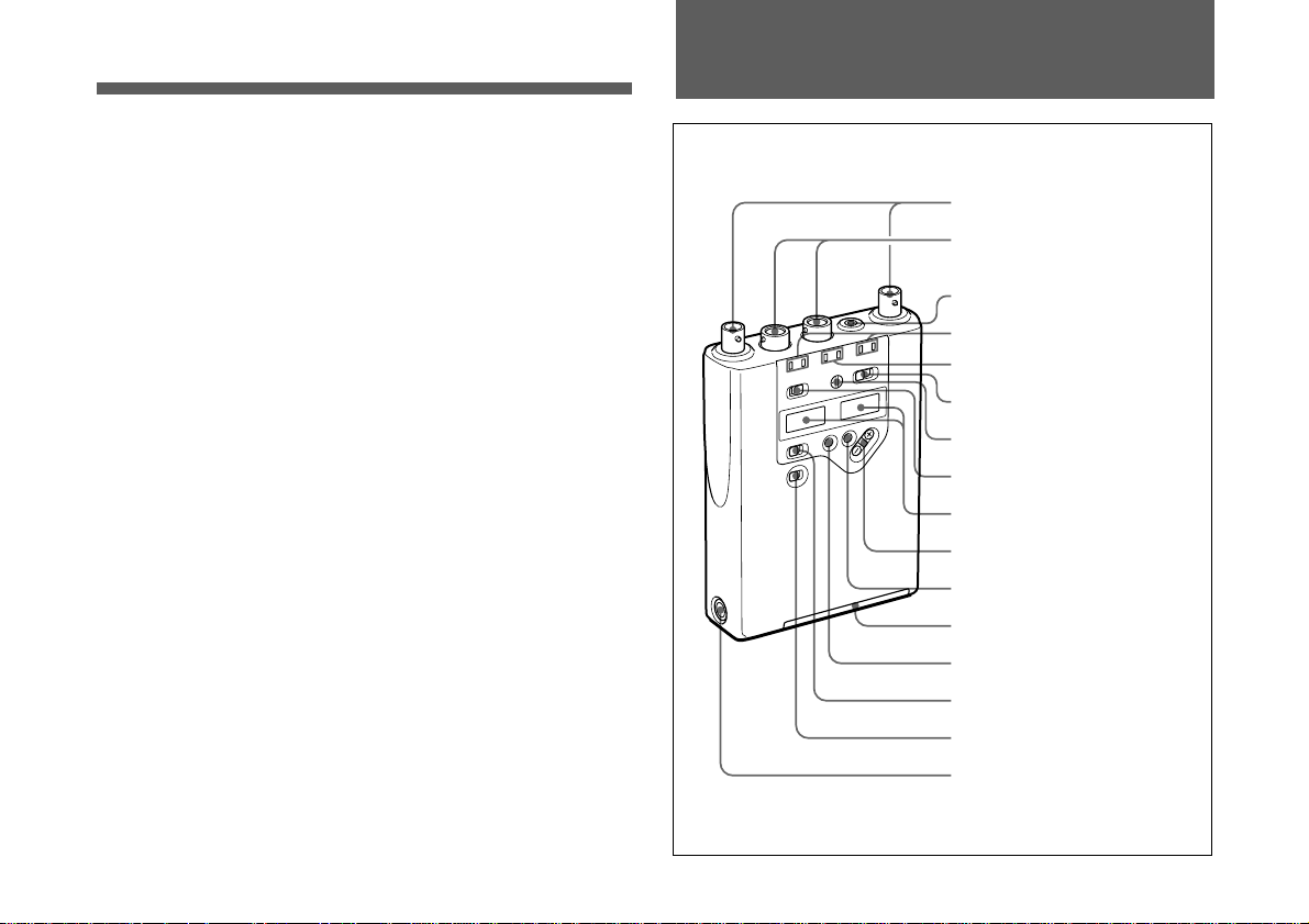
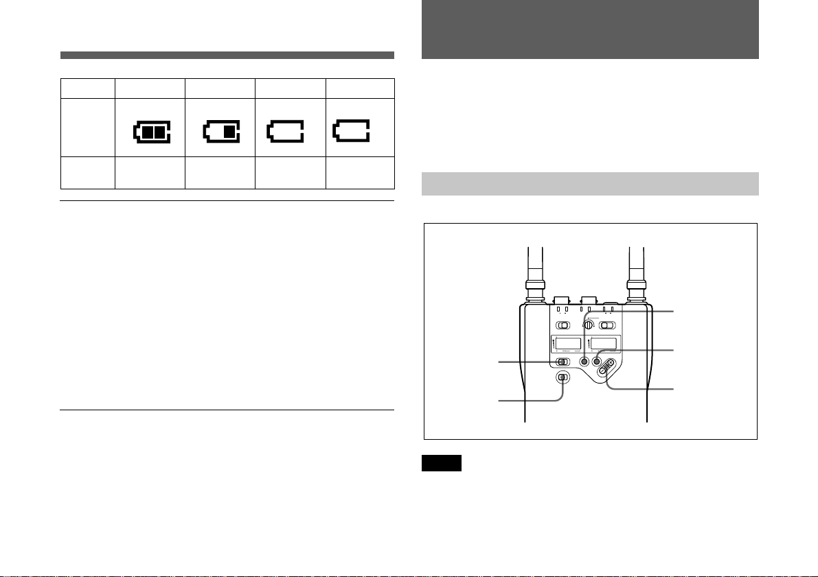
Parts Identification
1 ANT a/b connectors
2 OUTPUT 1/2 (BAL)
connectors
3 MONITOR connector
4 RF indicators
5 TX BATT indicators
6 MONITOR switch
7 MONITOR volume
8 SQUELCH switch
Output monitoring
Monitoring of the tuner 1, the tuner 2, or mixed 1 and 2
output is selectable. The monitor volume is adjustable with
a knob.
9 Display section
0 +/– buttons
qa SET button
Battery holder
qs MODE button
qd CONTROL switch
qf POWER switch
qg DC 12V IN connector
3
(GB)

Parts Identification
1 ANT (antenna) a/b connectors
Connect the antennas supplied to both ANT a/b connectors.
Note
Be sure to connect two antennas to these connectors, even
when you use one tuner, to make the diversity reception
properly.
2 OUTPUT 1/2 (BAL) connectors
The OUTPUT 1 connector supplies audio signal output
from tuner 1, and the OUTPUT 2 connector supplies the
output from tuner 2.
Connect these connectors to the microphone input
connector of a camcorder, mixer, or tape recorder by using
the supplied cable.
3 MONITOR connector
To monitor the tuner output, connect the headphones,
equipped with a 3.5 mm (5/32 inch) dia stereo mini jack.
Use either of stereo or monaural headphones. Select the
tuner to be monitored with the MONITOR switch, and
adjust the monitor level with the MONITOR volume.
4 RF (radio frequency) indicators
Indicate the strength of the RF input signal and the
receiving antenna for diversity reception of each tuner; the
left pair is for the tuner 1, and the right pair is for the tuner
2.
The indication color shows the strength of the RF input
signal. The indicated signal level changes corresponding to
4
(GB)
the squelch level setting.
When the squelch level is set to 5 dBµ;
On in green: RF input is more than 15 dBµ.
On in red: RF input is between 5 dBµ and 15 dBµ.
Off: RF input is less than 5 dBµ.
When the squelch level is set to 10 dBµ;
On in green: RF input is more than 20 dBµ.
On in red: RF input is between 10 dBµ and 20 dBµ.
Off: RF input is less than 10 dBµ.
When the squelch level is set to 15 dBµ;
On in green: RF input is more than 25 dBµ.
On in red: RF input is between 15 dBµ and 25 dBµ.
Off: RF input is less than 15 dBµ.
5 TX BATT (transmitter battery) indicators
Show the battery conditions of the two wireless microphone
transmitters independently. The indicators start flashing
about one hour before the transmitter batteries go flat.
6 MONITOR switch
Select the tuner to monitor. The “1+2” position allows to
monitor the mixed output of both tuners.
7 MONITOR volume
Turn to adjust the monitoring level through headphones.
8 SQUELCH switch
In ordinary use, set the switch to ON, and the noise and
signal interference will be eliminated when the tuner is in
signal reception stand-by mode. Set to OFF to search outside
noise or a radio wave which may disrupt the transmission.
Note
If you turn off the SQUELCH switch when the tuner is in
stand-by condition for signal receiving or when the RF input
level is low, noise may be heard or the connected device or
speakers may be damaged. Be sure to operate this switch
only after minimizing the input of the connected device.
See “Setting the Squelch Level” on page 10.
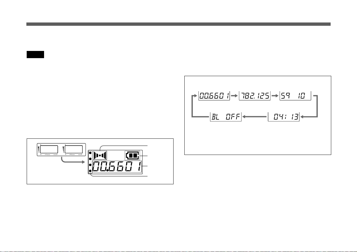
9 Display section
Shows the status of the tuner; the left display shows the
tuner 1, and the right shows the tuner 2.
For details of each indication, see A to D.
AFRF BATT
GP
CH GP
AFRF BATT
CH
A
B
C
C GP/CH (group/channel) indication
Shows the receiving channel group and channel number.
Each time you press the MODE button the group/channel
indication changes to the frequency, squelch level,
accumulated time of battery use and backlight mode
indications.
Group/channel
Backlight mode
Group/channel and frequency indications show those of
the U66 model as an example
Frequency Squelch level
Accumulated time
of battery use
For each item setting, see “Settings" from page 7 to 12.
D
A AF (audio frequency) indication
Lights when the output audio signal is over the reference
level.
B BATT (battery) indication
Displays the status of the batteries of this tuner.
See “Battery indication” on page 6.
D RF (radio frequency) indications
The number of dots shows the RF input level as below.
Four dots on: more than 35 dBµ
Three dots on: between 25 dBµ and 35 dBµ
Two dots on: between 15 dBµ and 25 dBµ
One dot on: between 5 dBµ and 15 dBµ
No dot: less than 5 dBµ
5
(GB)
Parts Identification
Power Supply
0 + (+ selection) / – (– selection/reset) buttons
When setting the transmission channel, frequency, squelch
level and backlight mode, press these buttons to change its
contents. The “–” button resets the accumulated time
indication to “00:00”.
qa SET button
Press to set and fix the item on the display.
qs MODE button
Press to select the item shown on the display.
qd CONTROL switch
Select the tuner to be set.
qf POWER switch
Turns the power of the tuner ON or OFF.
qg DC 12V IN connector
For external power operation, connect to an external power
supply (DC 10 V to 17 V) of a camcorder using the supplied
power cable.
For connecting the antennas, output cables and DC power
cable and attaching the unit to a camcorder, see
“Appendix” on page 15.
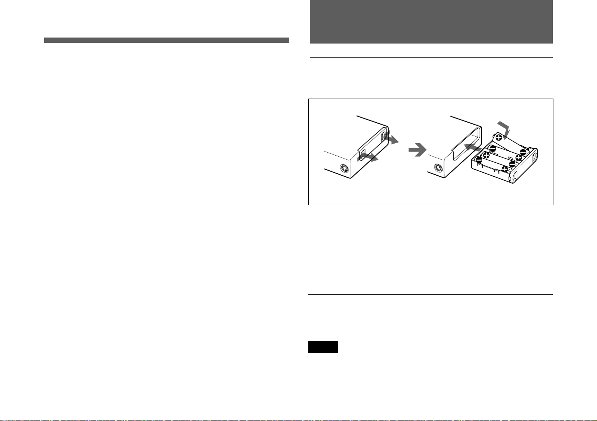
Installing the batteries
The tuner can operate on four LR6 (size AA) alkaline
batteries continuously for about 5 hours at 25°C (77 °F).
Four Alkaline batteries LR6 (sizeAA)
1 Slide the battery-holder catches inward to take out the
battery holder.
2 Match the polarities and insert the batteries.
3 Set the battery holder in the original position.
Confirm that both catches on the holder are locked.
Battery indication
When you turn the power on, the battery status of this unit
appears in the BATT indication on the display section.
Note
The indication may be incorrect if the batteries are not new
when installed. If you plan to use the tuner for a long
period, it is best to replace the batteries with new ones.
6
(GB)
Settings
1234
BATT
indication
BATT
condition
Lights Lights Lights
Good
Less than
50% charge
Less than
20% charge
Flashes
Almost
exhausted
Notes on batteries
Use new alkaline batteries.
•
Do not use different types of batteries together.
•
Always replace the four batteries together.
•
The batteries are not rechargeable.
•
Be careful to install the batteries with the correct polarity.
•
When not using the tuner for a long period, remove the
•
batteries to avoid leakage. If the batteries do leak, clean all
leakage from the battery holder case and the unit. Leakage
left in the holder case and the unit may cause poor battery
contact. If there seems to be poor battery contact, consult
your Sony dealer.
External power operation
To operate on an external power supply (DC 10 V to 17 V),
connect the DC 12V IN connector to the DC OUT connector
of a camcorder using the power cable supplied. When the
external power is supplied, the tuner functions regardless of
the built-in batteries.
To set the tuner in Setting Mode, press the SET button. The
indication on the display starts to flash waiting for you to
press the +/– buttons to change the contents on the display.
The Setting Mode is automatically cancelled if no buttons
are pressed for 30 seconds while the indication flashes.
Wireless Channel Selection
TX BATT
BRF
ON 1+2
AFRF BATT
CH GP
MODE SET
21
POWER
ABRF
12
CH
3
4,6,8
5,7
2
A
SQUELCH MONITOR
OFF
AFRF BATT
GP
CONTROL
OFF ON
1
Note
Noise may occur when the power is turned on or off. Be
sure to turn down the input level of the connected equipment
before operating the POWER switch.
7
(GB)
Settings
1 Set the POWER switch to ON.
The display shows the same status as before the tuner
was last turned off.
2 Set the CONTROL switch to “1” or “2”.
The tuner to be set is selected.
If the group name and channel number is shown on the
display, skip step 3 and proceed with step 4.
3 Press the MODE button until the group and channel
number appear on the display.
4 Press the SET button.
The group indication starts flashing.
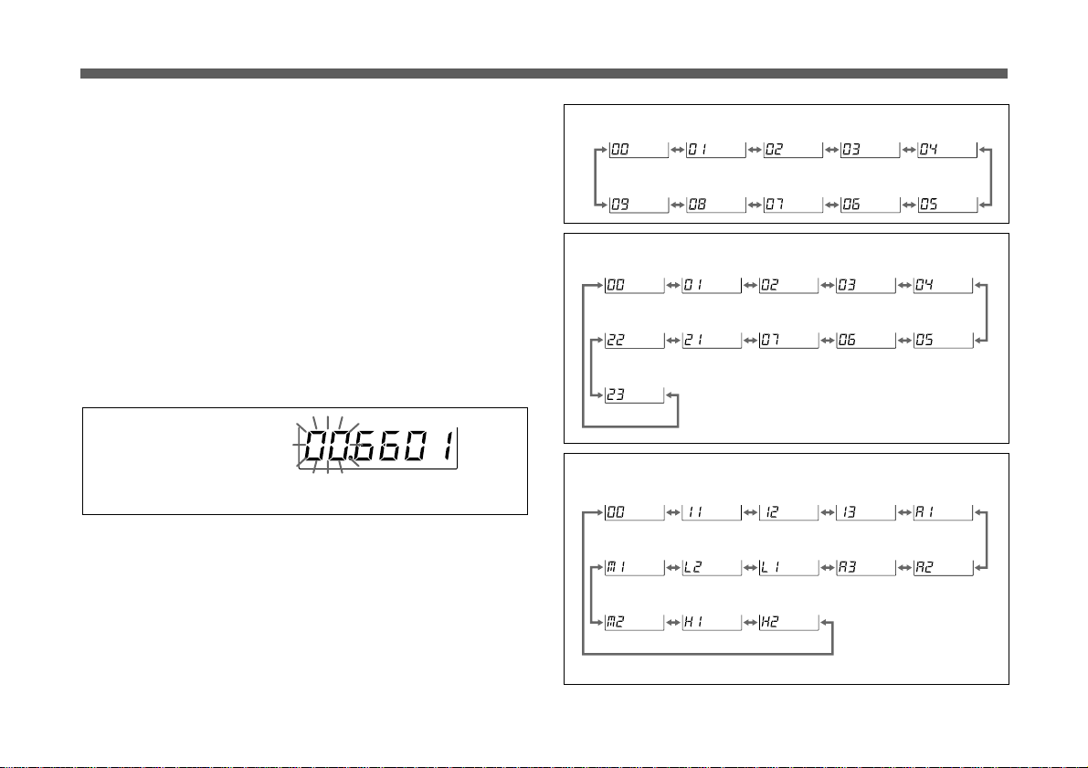
Group setting
Display example for U66 model
5 Press the + or – button to select the desired group.
Pressing the + button cyclically changes the group in the
following order. Pressing the – button changes it in the
reverse order.
Model available in USA
Model available in Europe (CE21)
Model available in Australia
If you hold the button down, the group will continuously
change.
8
(GB)
6 When the desired group appears, press the SET button
again.
The group selected is fixed.
The tuner now enters the wireless channel setting mode,
and both of the TV channel number and 2-digit number
flash on the display.
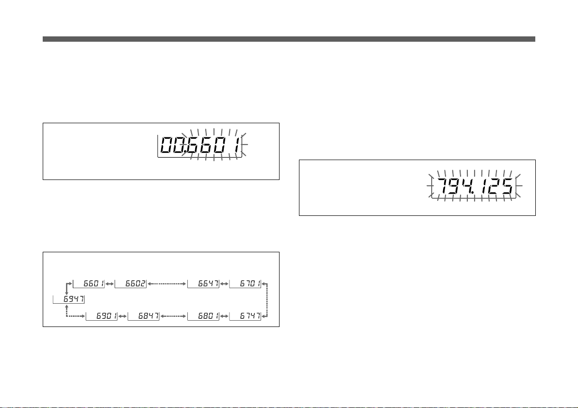
Channel setting
Display example for U66 model
7 Press the + or – button to select the desired wireless
channel.
The wireless channels change in the order listed on the
table of the group on the “Wireless Microphone System
Frequency List” supplied with this manual.
To select the channel by frequency indication
1 Turn on the unit, select the tuner to be set.
2 Press the MODE button until the frequency indication
appears.
3 Press the SET button.
The frequency indication starts flashing.
Display example for U66 model
4 Press the + or – button to select the desired channel
frequency.
When the group 00 is selected for U66 model
8 When the desired wireless channel appears, press the
SET button.
The display stops flashing and the selected group and
wireless channel are now stored in memory.
5 When the desired frequency appears, press the SET
button.
The display stops flashing and the selected wireless
channel is now stored in memory.
If noise is heard
Depending on the environment where the system is installed,
outside noise or radio wave may disrupt the transmission of
certain channels.
To select a channel under this circumstance, turn off the
wireless microphone or transmitter. Then select a channel at
9
(GB)
Settings
which the RF indicator is off. (A channel free from noise or
radio wave interference is selected.) Set the same channel on
the microphone or transmitter.
Notes
Do not remove the batteries during group and wireless
•
channel selection. If they are inadvertently removed, reinsert them immediately and repeat the steps on pages 7 to
9 from the beginning.
Make sure that the channel selected is the same as that
•
selected on the transmitter used in the same system.
Be sure to set tuners 1 and 2 to different channels.
•
Depending on the noise or interference conditions, the
•
selectable channels may not necessarily all be usable. If
necessary, you can determine the usable channels by
stepping the channel selection through a number of
channels on the tuner with the microphone/transmitter set
to OFF. Those channels on which the RF indicator of the
tuner does not light are usable.
If there is a TV broadcasting station near by, do not use
•
the station's channel.
The unit may not operate correctly if it is turned on again
•
immediately after turning off the power while in setting
mode. Pause for a few seconds or more before turning on
the power again.
When operating the unit with one transmitter (for
•
example, using tuner 1 for reception, and leaving tuner 2
unused), noise or audio signals may occur on the unused
tuner, if the tuner and the transmitter are too close to each
10
(GB)
other. In such a case, keep a enough distance to ensure
the proper performance of the unit.
When operating two or more UHF wireless microphone
•
systems using channels in different groups, ensure that the
systems are at least 100 m (330 feet) apart from each
other. (The same applies also when using channels in a
group if the different UHF wireless microphone systems
are installed where they are within sight of each other.)
Setting the Squelch Level
You can eliminate the noise and signal interference which
may occur in reception stand-by mode. Select a squelch
level from 5 dBµ, 10 dBµ or 15 dBµ. The factory preset
level is 10 dBµ. To obtain a wide service area, set this to
5 dBµ. When using the tuner in a multi-channel system or
when you want to receive noise free audio input all the time,
set it to 15 dBµ.
1 Press the MODE button until the squelch level appears.
2 Press the SET button.
The squelch level indication starts flashing.
Squelch level
3 Press the + or – button to select the desired level.
Resetting the Accumulated Time Indication
4 When the desired level appears, press the SET button.
The display stops flashing and the selected level is now
stored in memory.
Squelch functions
When the SQUELCH switch is set to ON, the following functions
work in combination.
(1) Squelching by RF input level
As sufficient S/N for the audio output may not be obtained if no RF
signal is received or the RF input level is low, the audio output is
squelched when the RF input level falls below the squelch level
selected.
(2) Tone squelch
The audio output is obtained only when the unit receives an RF
signal which includes a specified tone signal. The audio output is
squelched to eliminate noise which may be heard when the
transmitter is turned on/off or the unit receives an interference RF
signal.
(3) Noise squelch
The audio output is squelched to eliminate noise which may be
heard when there is such excessive interference RF signal that the
tone squelch does not work.
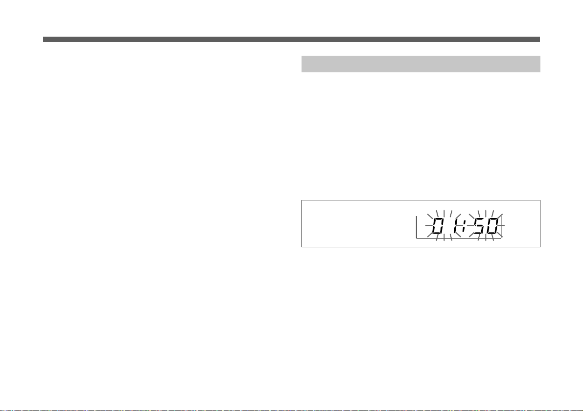
The time indication accumulates time in hours and minutes
when the WRR-862A/862B is on.
Reset the indication to “00:00” whenever you replace the
batteries so that it can display the running time of the
batteries.
1 Press the MODE button until the accumulated time
appears.
2 Press the SET button.
Accumulated time of
battery use
3 Press the – button.
The time indication resets to “00:00.”
While you see “00:00” is flashing, you can go back to
previous value by pressing the + button.
4 Press the SET button.
11
(GB)
Settings
Error Messages
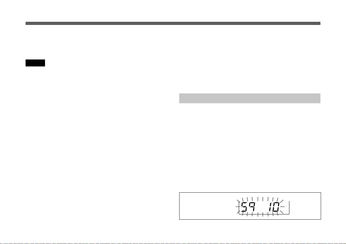
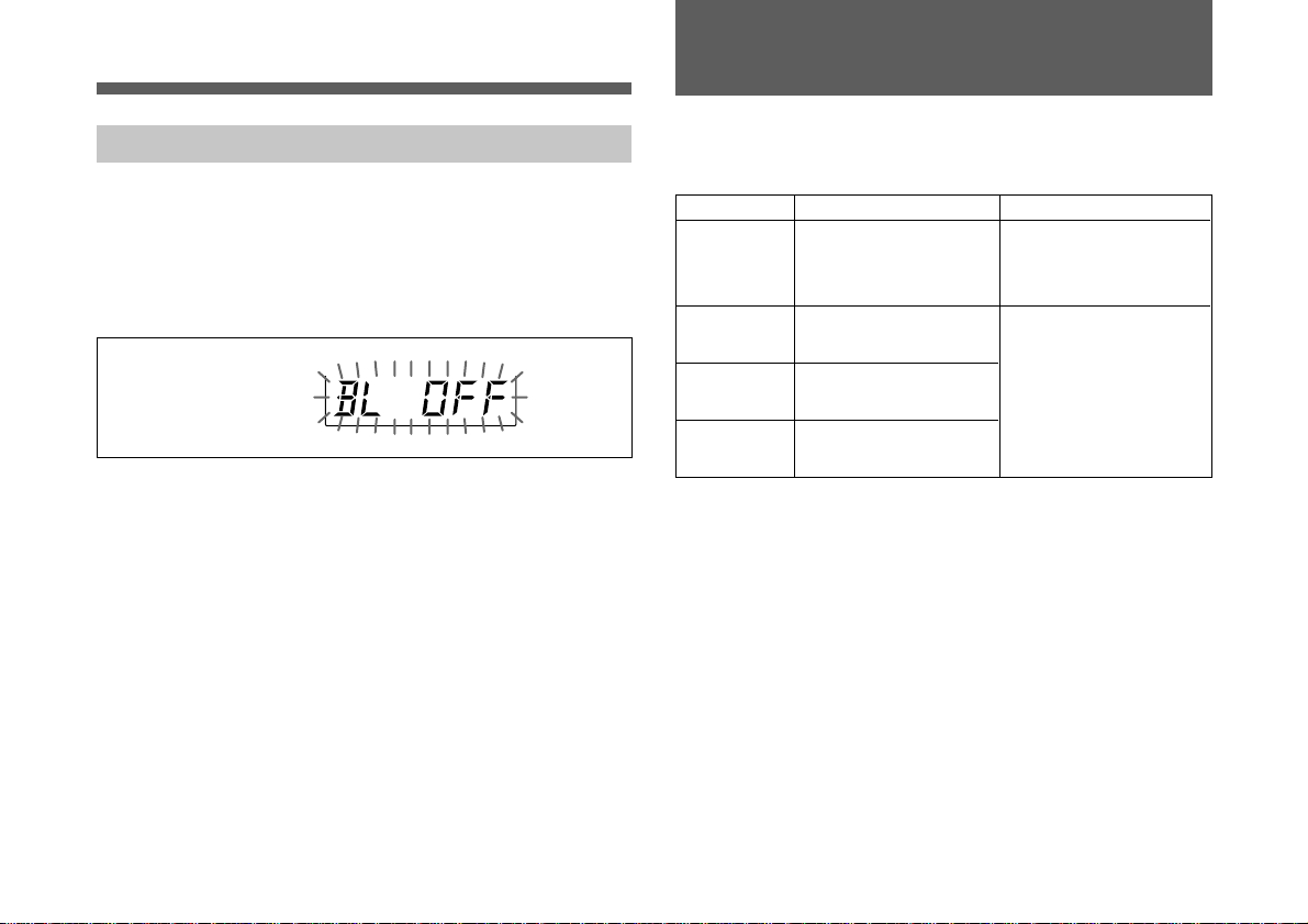
Selecting the Backlight Mode
You can select the backlight mode of the display.
1 Press the MODE button until the backlight mode appears.
2 Press the SET button.
The backlight indication starts flashing.
Backlight mode
3 Press the + or – button to select the desired mode.
BL OFF : Lights off all the time
BL ON : Lights on all the time
BL AT : Lights on when you begin to operate the
tuner. Turns off automatically 15 seconds
after you finish operation.
4 When the desired mode appears, press the SET button.
The display stops flashing and the selected mode is now
stored in memory.
When a problem occurs, one of the following error message
may appear on the display.
Messages
ERROR 03
ERROR 11
ERROR 21
ERROR 51
Contents
The battery voltage
exceeds the allowable
value.
An error occurred in
backup memory data.
The PLL synthesized
circuit is in trouble.
Defect of the A/D
converter.
Measures
Use the specified
batteries.
Contact your Sony
dealer.
12
(GB)

Specifications
Tuner section
Type of reception Space diversity
Circuit system Dual conversion superheterodyne
Receiving frequencies
Model available in USA:
two frequencies within a 24
MHz frequency band selected
from 470 to 806 MHz
Model available in Europe:
two frequencies within a 24
MHz frequency band selected
from 470 to 862 MHz
Model available in Australia:
two frequencies within 792 to
806 MHz
Local oscillators 1st: Crystal controlled PLL
synthesizer
2nd: Crystal oscillator
Antenna connectors BNC-R (2)
RF input impedance 50 Ω
RF squelch level 5 dBµ /10 dBµ /15 dBµ or OFF
selectable
Frequency response 40 Hz to 18 kHz
De-emphasis 50 µs
Selectivity 60 dB or more
(at ±250 kHz detuned)
Spurious rejection ratio 70 dB or more
.............................................................................................................................................................................................................................................................
0 dBµ = 1 µV
0 dBm = 0.775 Vrms (600 Ω loaded)
EMF
Image rejection ratio 60 dB or more
Signal-to-noise ratio 30 dB or more at 10 dBµ RF input
60 dB or more at 60 dBµ RF input
(±5 kHz deviation at 1 kHz
modulation, A-weighted)
Distortion 1% or less
(±40 kHz deviation at 1 kHz
modulation)
Tone squelch frequency 32.768 kHz
Output connectors SMC9-4S (2)
Output level –58 dBm
(±5 kHz deviation at 1 kHz
modulation)
Output impedance 150 Ω, balanced
Monitor connector 3.5 mm (5/32 inch) dia.
stereo mini jack
General
Power requirements
Batteries: 6 V DC , four
alkaline
batteries LR6 (size AA)
External: 12V DC
Current consumption Batteries: Approx. 230 mA
at 6V DC
External: Approx. 135 mA
at 12 V DC
Battery life 5 hours or more of continuous use
with four Sony LR6 alkaline
batteries at 25°C
13
(GB)

Specifications
Operating temperature
0 °C to +50 °C (32 °F to 122 °F)
Storage temperature –20 °C to +60 °C
(–4 °F to +140 °F)
Dimensions 89 × 120 × 29.5 mm (w/h/d)
(35/8 × 43/4 × 13/16 inches)
Mass 400 g (14 oz) including batteries
Supplied accessories
Antennas (2)
Output cables (2)
DC power cable (1)
Mounting plate (1)
Attachment case (1)
Operating instructions (1)
Wireless Microphone System Frequency List (1)
Optional accessory
Mounting bracket (A-8278-057-A)
Design and specifications are subject to change without notice.
14
(GB)
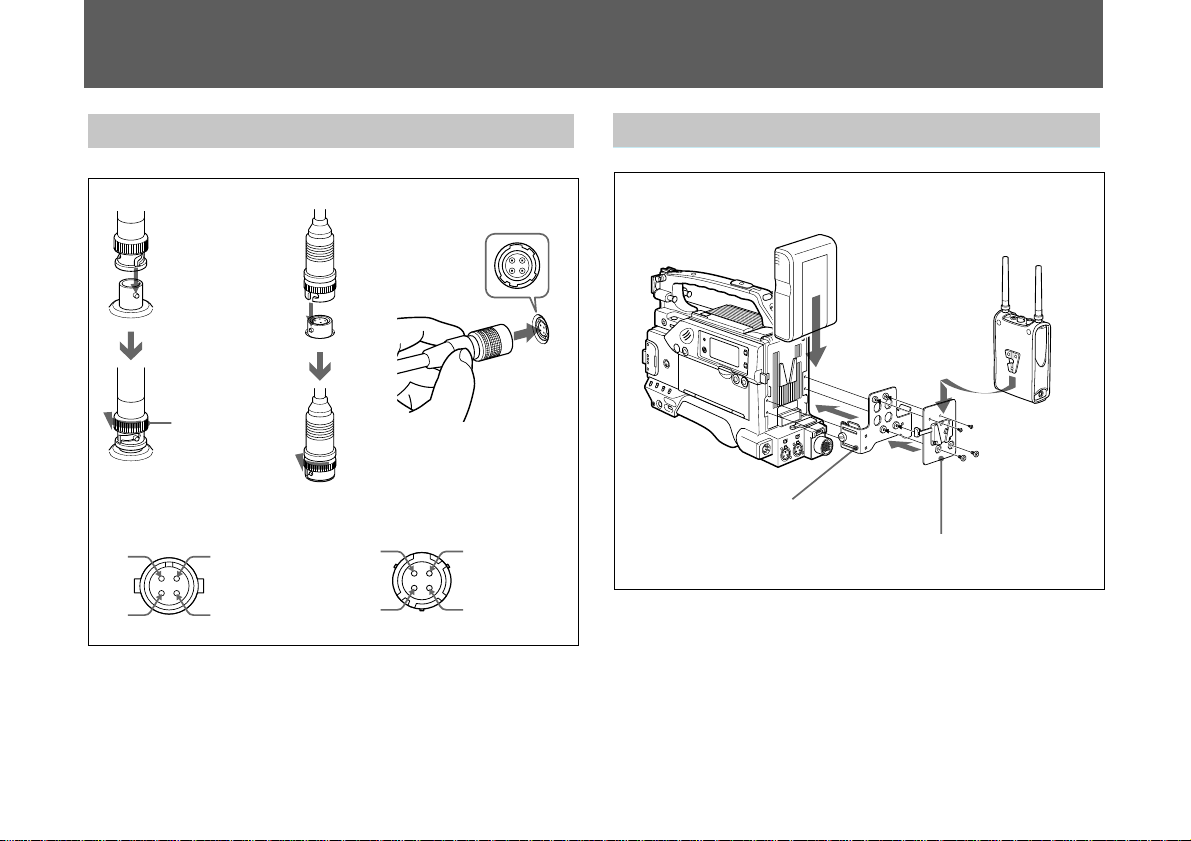
Appendix
Attaching to a CamcorderConnections
Antenna
Turn the
connector
cover to
lock.
OUTPUT 1/2 (BAL)
4
3
1
2
Output cable
1: NC
2: Hot
3: Cold
4: GND
DC power cable
DC 12V IN
4
3
1
2
1: GND
2: NC
3: NC
4: +12V
When connecting antennas and cables, match the guides of
the male and female connectors.
The DC power cable can be released by pulling out the
connector cover.
Sony lithium-ion battery pack BP-L60/L60A
Mounting bracket optional
(A-8278-057-A)
Mounting plate supplied
When the Sony lithium-ion battery pack BP-L60/L60A is
attached on the camcorder, both the mounting bracket
optional (A-8278-057-A) and the mounting plate supplied
are required. When attaching the Sony nickel-cadmium
battery, use only the supplied mounting plate.
To release the tuner from the mounting plate, push in the
lever on the plate.
15
(GB)

16
(GB)

Français
Table des matières
Précautions
Précautions ......................................................................... 1
Introduction ....................................................................... 2
Caractéristiques.............................................................. 2
Identification des pièces .................................................... 3
Alimentation....................................................................... 7
Réglages .............................................................................. 8
Sélection d’un canal sans fil .......................................... 8
Réglage du niveau du silencieux ................................. 11
Remise à zéro de l’indication de temps cumulé .......... 12
Sélection du mode de rétro-éclairage........................... 12
Messages d’erreur ........................................................... 13
Spécifications.................................................................... 14
Annexe .............................................................................. 16
Raccordements............................................................. 16
Raccordement à un caméscope .................................... 16
• Cet appareil est conçu pour utilisation à une température
ambiante de 0 à 50 °C.
• Ne pas placer cet appareil sur ou près des sources de
chaleur comme le matériel d’éclairage ou les
amplificateurs, ou dans un endroit exposé au soleil ou à
une humidité excessive, au risque d’endommager la
finition extérieure ou les composants internes de
l’appareil.
• Si l’appareil est utilisé dans un endroit très humide ou
poussiéreux ou dans un endroit soumis à un gaz actif ou
corrosif, nettoyez sa surface ainsi que les connecteurs avec
un chiffon doux et sec, immédiatement après l’utilisation.
L’utilisation prolongée de l’appareil dans de tels endroits
ou l’absence de nettoyage après utilisation dans de tels
endroits est susceptible de raccourcir sa durée de vie.
• Ne jamais utiliser de dissolvant organique tel que du
diluant ou du benzène pour le nettoyage, au risque
d’endommager la finition de l’appareil.
• L’appareil a été réglé avec précision en usine. Ne pas
modifier les composants internes ni essayer de les réparer.
FR
Français
1
(FR)
 Loading...