

Sony WRR-855A, WRR-855B User Manual
UHF Synthesized
Tuner Unit
3-205-489-13 (1)
Operating Instructions
Mode d'emploi
Bedienungsanleitung
Manual de instrucciones
WRR-855A/WRR-855B
2000 Sony Corporation
GB
FR
DE
ES

Owner’s Record
The model and serial numbers are located at the rear of the
unit. Record the serial number in the space provided below.
Refer to these numbers whenever you call upon your Sony
dealer regarding this product.
Model No. WRR-855A/855B Serial No.
Notice for customers in the U.S.A.
You are cautioned that any changes or modifications not
expressly approved in this manual could void your authority
to operate this equipment.
If you have any questions about this product, you
may call:
Sony's Business Information Center (BIC)
at 1-800-686-SONY (7669)
or Write to:
Sony Customer Information Services Center
6900-29 Daniels Parkway, PMB 330 Fort Myers,
Florida 33912
Declaration of Conformity
Trade Name: SONY
Model No.: WRR-855B
Responsible Party: Sony Electronics Inc.
Address: 1 Sony Drive, Park Ridge,
NJ.07656 U.S.A.
Telephone No.: 201-930-6972
This device complies with Part 15 of the FCC Rules.
Operation is subject to the following two conditions:
(1) This device may not cause harmful interference, and
(2) this device must accept any interference received,
including interference that may cause undesired
operation.
II

Notice for customers in Canada:
Use of Sony wireless devices is regulated by the Industry
Canada as described in their Radio Standard Specification
RSS-123.
A licence is normally required. The local district office of
Industry Canada should therefore be contacted. When the
operation of the device is within the broadcast band, the
licence is issued on no-interference, no-protection basis with
respect to broadcast signals.
Operation of this device is subject to the following two
conditions: (1) this device may not cause interference, and
(2) this device must accept any interference, including
interference that may cause undesired operation of the
device.
Avis pour les clients au Canada:
L’usage des appareils sans-fil Sony est réglé par l’Industrie
Canada comme décrit dans leur Cahier des Normes
Radioélectriques CNR-123.
Une licence est normalement requise. Le bureau de
l’Industrie Canada doit être contacté. Lorsque l’opération de
l’appareil est dans les limites de la bande de radiodiffusion,
la licence est émanée sur la base de non-interférence, nonprotection avec les signaux de radiodiffusion.
L’utilisation de cet appareil est soumise aux deux conditions
suivantes : (1) cet appareil ne peut causer d’interférences,
et (2) cet appareil doit accepter toutes les interférences, y
compris les interférences capables de provoquer un
fonctionnement indésirable de l’appareil.
III

Notice for customers in Europe
Spécifications particulières pour les consommateurs européens
Hinweis für Kunden in Europa
Aviso para los usuarios en Europa
U.K. 854.125 - 862 MHz
Germany 798 - 822 MHz
Norway 800 - 820 MHz
Luxembourg 800 - 830 MHz, 854.125 - 862 MHz
Belgium 854.125 - 862 MHz
Denmark 800.100 - 819.900 MHz
France 470 - 830 MHz
Italy 800 - 820 MHz
Sweden 800 - 820 MHz
Switzerland 800 - 820 MHz
Finland 800 - 814 MHz
Iceland 800 - 814 MHz
Austria 774 - 790 MHz
Netherland 774 - 782 MHz
IV
Hereby, Sony Corporation, declares that this WRR-855B is
in compliance with the essential requirements and other
relevant provisions of Directive 1999/5/EC.
Sony Corporation déclare par la présente que ce WRR-855B
est conforme aux exigences fondamentales et aux autres
dispositions applicables de la Directive 1999/5/CE.
Hiermit erklärt die Sony Corporation, daß das Modell
WRR-855B die grundlegenden Anforderungen und sonstigen
relevanten Bestimmungen der Richtlinie 1999/5/EU erfüllt.
Por la presente, Sony Corporation, declara que este
WRR-855B cumple con los requisitos esenciales y otras
disposiciones pertinentes de la Directiva 1999/5/CE.

English
Table of Contents
Precautions
Precautions......................................................................... 1
Overview.............................................................................2
Features .......................................................................... 2
Parts Identification ............................................................ 4
WRR-855A/855B .......................................................... 5
BTA-801 Portable Tuner Mount
Adapter (Optional) .................................................... 6
Preparations ....................................................................... 7
Mounting to a Portable Tuner Mount Adapter .............. 7
Connecting the Power Cable.......................................... 8
Attaching the Antennas.................................................. 8
Settings................................................................................ 9
Channel Selection .......................................................... 9
Setting and Releasing
the T (Tone Squelch) OFF Mode............................ 12
Attaching and Connecting to a Betacam ....................... 13
Messages on the Display.................................................. 15
Specifications.................................................................... 15
On operation
The tuner unit must be used within the temperature range
•
of 0°C to 50°C (32°F to 122°F). Avoid using for an
extended period of time in extremely high temperature, or
the place subject to direct sunlight, especially outdoors,
because the finish of the case might be damaged.
Never install the tuner on or near heat sources, such as
lighting equipment, power amplifiers.
The tuner is designed to be portable and is built to resist
•
humidity and dust. However, try to avoid using in very
humid or dusty places, because such use may shorten the
life of the tuner unit.
To avoid degradation of the signal-to-noise ratio, do not
•
use the tuner in noisy places or in locations subject to
vibration, for example:
–near electric equipment such as motors, transformers or
dimmers
–near air conditioning equipment or places subject to direct
air flow from an air conditioner
–near a public address loudspeaker
–in a location where adjacent equipment might knock
against the tuner.
The switching of lights may produce electrical interference
•
over the entire frequency range.
Position the tuner and the wireless microphone in a place
where such interference is at minimum.
The unit has been factory adjusted precisely. Do not
•
tamper with its internal parts or attempt to repair it.
GB
English
1
(GB)
Precautions
Overview
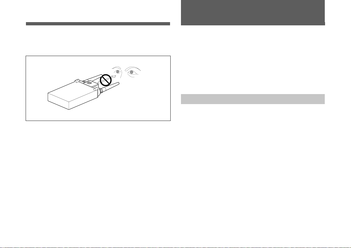
When looking into the upper-panel displays, be careful to
•
keep a sufficient distance between your eyes and the tuner
unit.
S
On cleaning
Clean the tuner unit with a dry, soft cloth. Never use thinner
or benzine, since these will damage the finish.
2
(GB)
The WRR-855A/855B UHF Synthesized Tuner Unit in use
with an optional Portable Tuner Mount Adapter, such as the
BTA-801, provides a highly reliable portable diversity tuner
for the Sony UHF wireless microphone system, which uses
the frequency bands allocated for UHF TV broadcasting.
This tuner enables the application of multiple channels over
unused television channels through the use of the built-in
Sony original channel plan.
Features
Wide Operating Frequency ranges
The WRR-855A operates over a 14 MHz frequency band
within the range of 792 MHz to 806 MHz (model available
in Australia) , while the WRR-855B operates over a 24 MHz
frequency band between 470 MHz to 806 MHz (model
available in U.S.A.), or 470 MHz to 862 MHz (model
available in Europe).
WRR-855A
Model available in Australia:
792 to 806 MHz, TV channels 66 to 67
WRR-855B
Model available in USA:
470 to 806 MHz, TV channels 14 to 69
(14 frequency band, divided into 24 MHz range. All 14
frequency bands may not be available in some areas.)
Model available in Europe:
470 to 862 MHz, TV channels 21 to 69
(17 frequency band, divided into 24 MHz range. All 17
frequency bands may not be available in some areas.)

Preprogrammed wireless channel plans for simultaneous
multi channel operation
The WRR-855A/855B has many preprogrammed channel
groups, meaning combination of wireless channels to permit
simultaneous operation of multiple channels without
intermodulation.
For the channel plans available on your unit, see “Wireless
Microphone System Frequency List” supplied with this
manual.
Space diversity reception system
The WRR-855A/855B provides stable signal reception with
only a minute amount of dropout.
Versatile display
A variety of information is obtained at a glance on the upper
panel, such as the reception channel with the liquid-crystal
display, and RF input level and audio level with the
respective LEDs.
Compact and lightweight
Innovative, high-density mounting technology has enabled
the creation of this compact, lightweight tuner. Using the
optional BTA-801 Portable Tuner Mount Adapter in
combination, the WRR-855A/855B can be easily attached to
a Betacam-series Camcorder.
Weatherproof structure
By properly mounting the WRR-855A/855B to the optional
BTA-801 Portable Tuner Mount Adapter and attaching the
two supplied antennas, a weatherproof structure is obtained.
Muting ON/OFF function
You can activate or deactivate the muting function to suit
your needs.
Tone-squelch circuit for noise elimination
The unit uses a built-in squelch circuit to selectively receive
the desired RF carrier accompanied by the tone signal from
the transmitter.
Compander system
A compander (compressor/expander) system enables
stabilized wireless transmission over a wide dynamic range.
3
(GB)
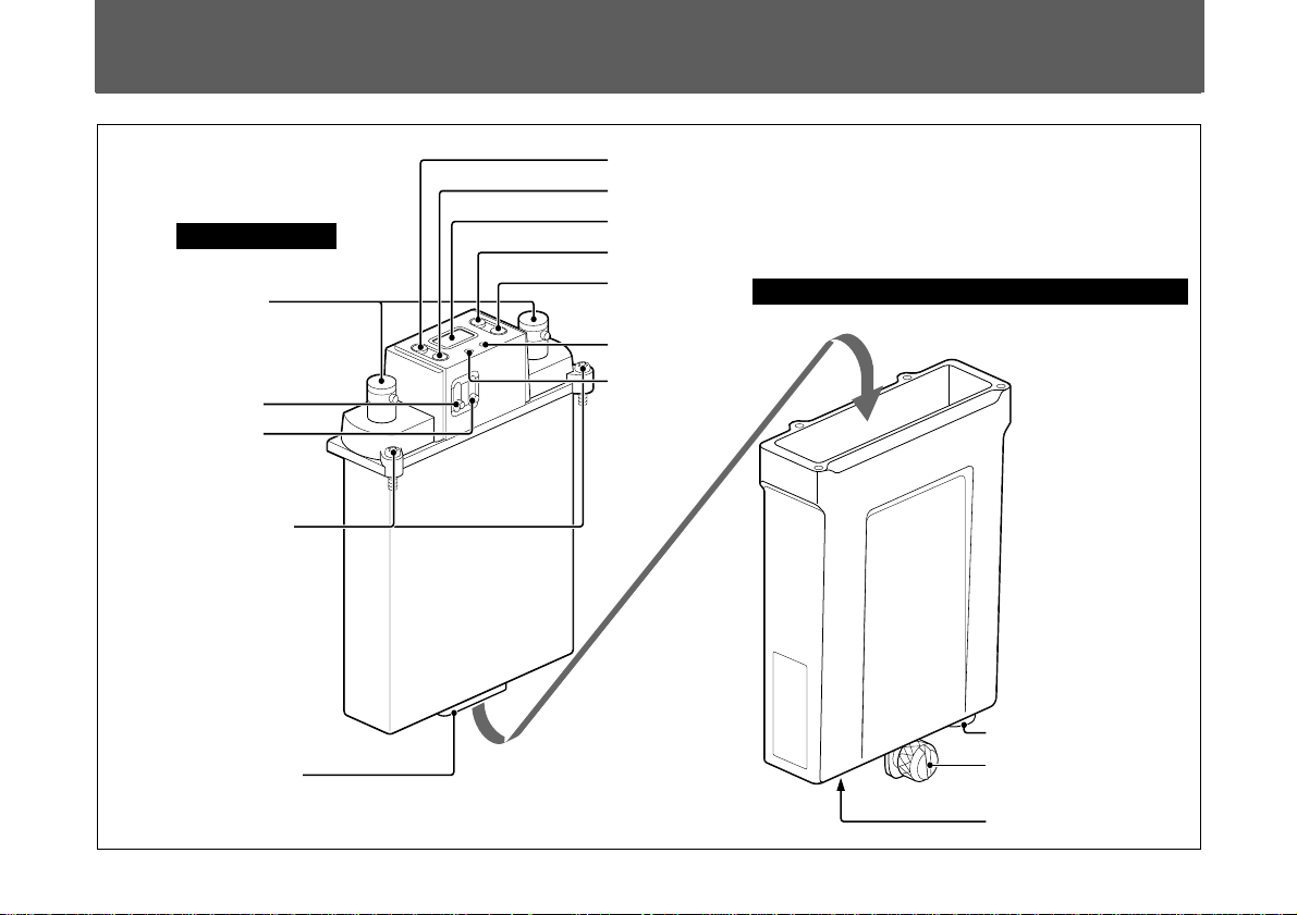
Parts Identification
WRR-855A/855B
1 ANT connectors
GP/CH
GP
2 POWER switch
3 MUTING switch
4 Mounting screws (4)
+
–
AF
RF
CH
MUTING
ON
POWER
OFF
UHF SYNTHESIZED
TUNER UNIT WRR-855
6 GP button
7 CH button
8 Liquid-crystal display
9 + button
0 – button
S
qa AF indicator
BTA-801 Portable Tuner Mount Adapter (optional)
qs RF indicator
5 Accessory connector
4
(GB)
qd DC 12V IN connector
qf Betacam attachment
knob
qg OUTPUT connector
WRR-855A/855B
5 Accessory connector
For the signal and power connections with the BTA-801.
1 ANT (antenna) connectors
Connect the two supplied antennas to these connectors.
2 POWER switch
Turns the power ON/OFF.
3 MUTING switch
Turns the muting ON/OFF. The muting level is fixed at
10 dBµ.
Note
If you turn off the muting when the tuner is in standby
condition for signal receiving or when the RF input level is
low, noise may be heard or the connected device or speakers
may be damaged. Be sure to operate this switch only after
minimizing the input of the connected device.
4 Mounting screws
Used to secure the WRR-855A/855B to the BTA-801.
For mounting, see “Mounting to a Portable Tuner Mount
Adapter” on page 7.
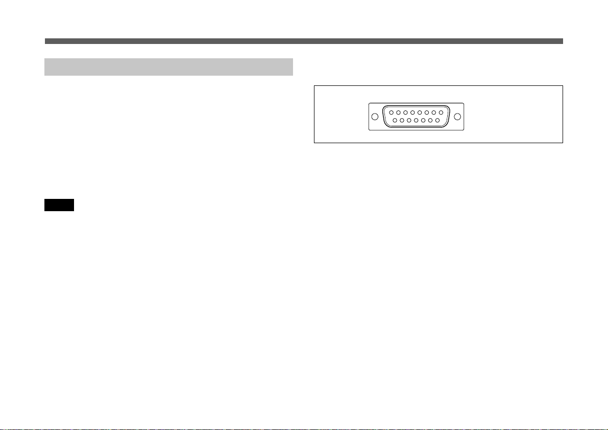
Pin assignment
1
9
8
15
1: AF GND
2: AF OUTPUT
4: DC +7V
5: GND
6 GP (group set) button
Press and hold down for at least one second to go to the
group selection mode, and the group number flashes on the
display.
See “Settings” on page 9.
7 CH (channel set) button
Press and hold down for at least one second to go to the
channel selection mode and the channel number flashes on
the display.
See “Settings” on page 10.
8 Liquid-crystal display
On the WRR-855A: When you turn the power ON, the
“HELLO” message appears, then the tuner unit goes to
normal display mode.
On the WRR-855B: When you turn the power ON, the
version number of your tuner (for example “U66”)
appears, then the tuner unit goes to normal display mode.
5
(GB)
Parts Identification
9 + button / 0 – button
Press to select the group and channel numbers to be
received.
See “Settings” on pages 10 and 11.
qa AF (audio frequency level) indicator
Lights when an audio signal greater than the reference level
is output.
qs RF (radio frequency input level) indicator
Displays the strength of the input signal.
Lights in green: Higher than 25 dBµ
Lights in red: 10 to 25 dBµ
Goes off: Lower than 10 dBµ
BTA-801 Portable Tuner Mount Adapter (Optional)
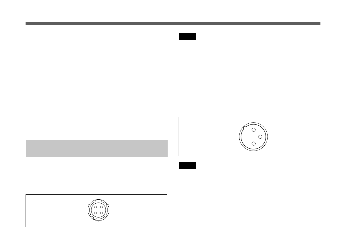
qd DC 12V IN (power input) connector
Connect to an external power supply (DC 10 to 17 V) of a
Betacam using the DC power cable supplied with the
BTA-801.
Pin assignment
4
4
1
1
2
2
3
3
1: GND
2: NC
3: NC
4: +12 V
Note
Be sure to check the operating voltage and polarity when
connecting to a power source.
qf Betacam attachment knob
Used to fix the unit to a Betacam.
For attaching the unit to a Betacam, see page 13.
qg OUTPUT connector (XLR 3-pin, male)
Supplies audio signals. You can connect this to the
microphone input connector of a Betacam, mixer, tape
recorder or other similar equipment.
Pin assignment
Note
2
3
1
1: GND
2: HOT
3: COLD
When connecting to an audio mixer which has a Phantom
powering capability for microphones, it is recommended to
use the mixer with the Phantom power OFF.
6
(GB)
Preparations
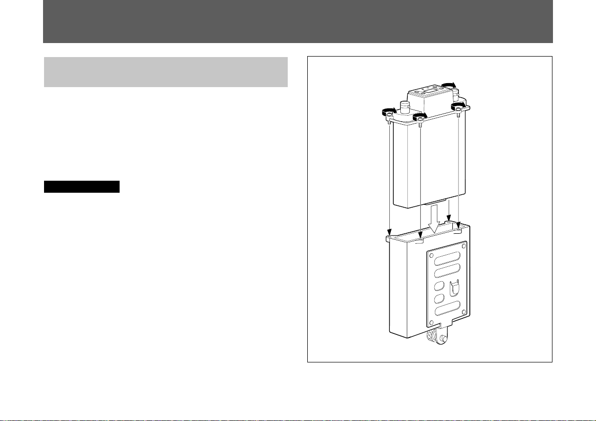
Mounting to a Portable Tuner Mount Adapter
This section shows you how to mount the
WRR-855A/855B to the BTA-801 Portable Tuner Mount
Adapter for example.
By properly mounting the WRR-855A/855B to the
BTA-801 and attaching the two supplied antennas, a
weatherproof structure is obtained.
Before mounting
Be sure to clean the abutting surfaces of the
WRR-855A/855B and the BTA-801 before mounting.
Procedure for mounting to the BTA-801
WRR-855A/855B
1 Observing the direction, insert the WRR-855A/855B in
the BTA-801.
2 Push the WRR-855A/855B until the accessory connector
clicks into place.
3 Run in the four mounting screws little by little in turn to
gradually secure the units together, then tighten them.
BTA-801
7
(GB)
Preparations
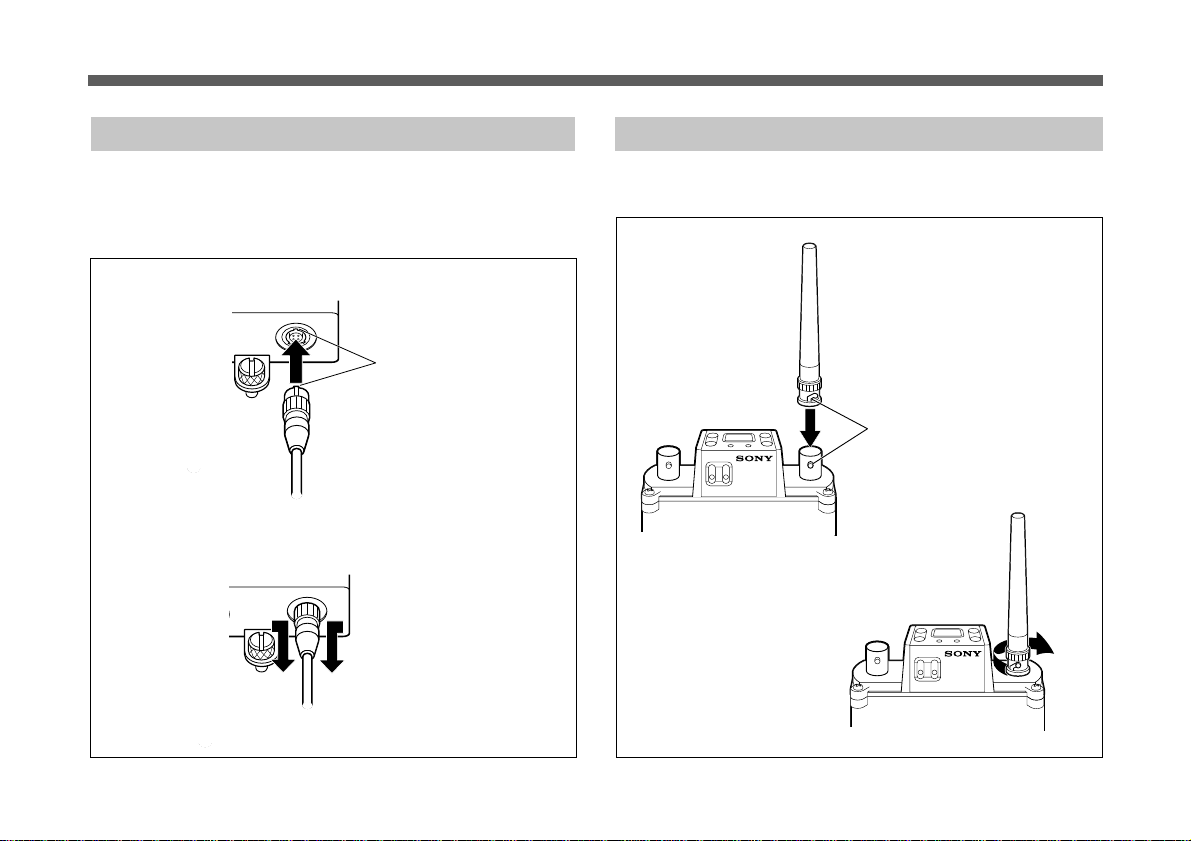
Connecting the Power Cable
Connect the DC 12 V IN connector of the BTA-801 to the
DC OUT connector of a Betacam-series Camcorder using
the DC power cable supplied with the BTA-801.
BTA-801 (bottom)
To remove: Pull the metal part of the connector in the
direction of the arrow and remove.
Match the connector pins
with the connector inside
and insert.
DC power cable
(supplied with the BTA-801)
Attaching the Antennas
Attach the supplied antennas to the two ANT connectors.
1 Align the protruding part
of the connector with the
antenna slot.
2 Turn to lock.
8
(GB)
Settings
Channel Selection
Notes
Take the following precautions to prevent interference and
noise.
• Do not simultaneously use two or more microphones and
transmitters that are set to the same channel.
• When using two or more tuners simultaneously, always set
the tuners that use the same groups (other than group 00) to
different channels in that group.
• The reception antennas and transmitter should be used at
least 3 meters away from each other.
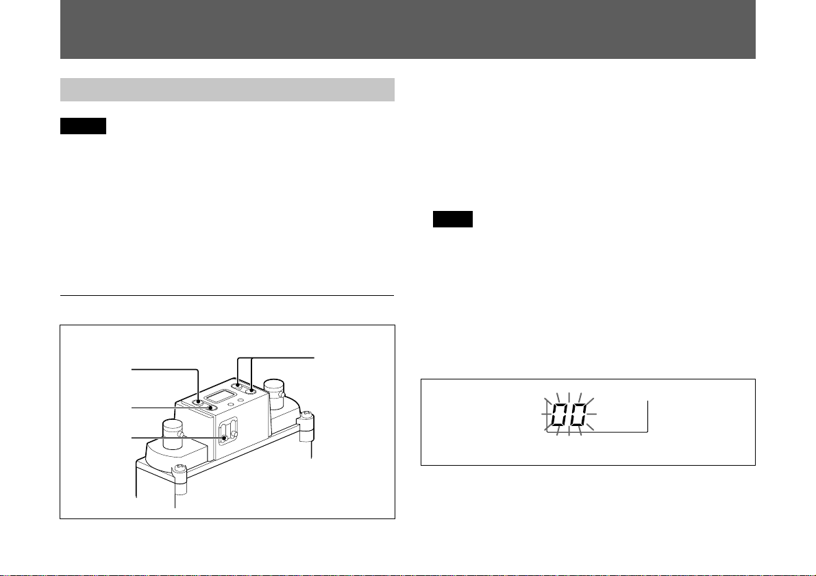
Operations
2
4
1
GP/CH
P
G
+
–
F
A
F
R
H
C
S
MUTING
ON
POWER
OFF
UHF SYNTHESIZED
TUNER UNIT WRR-855
3,5
1 Turn the POWER switch ON.
On the WRR-855A, the “HELLO” message appears on
the display, then it changes to the tuner status indication
shown before the tuner was previously turned off.
On the WRR-855B, the version number of your tuner (for
example “U66”) appears, then it changes to the tuner
status indication shown before the tuner was previously
turned off.
Note
POWER switch operation should be performed after
disconnecting the input from connected equipment, as
noise will be heard if the switch is turned ON or OFF
beforehand.
2 Press and hold the GP button down for more than one
second.
The tuner goes to the group selection mode and the group
number flashes.
Group
selection mode
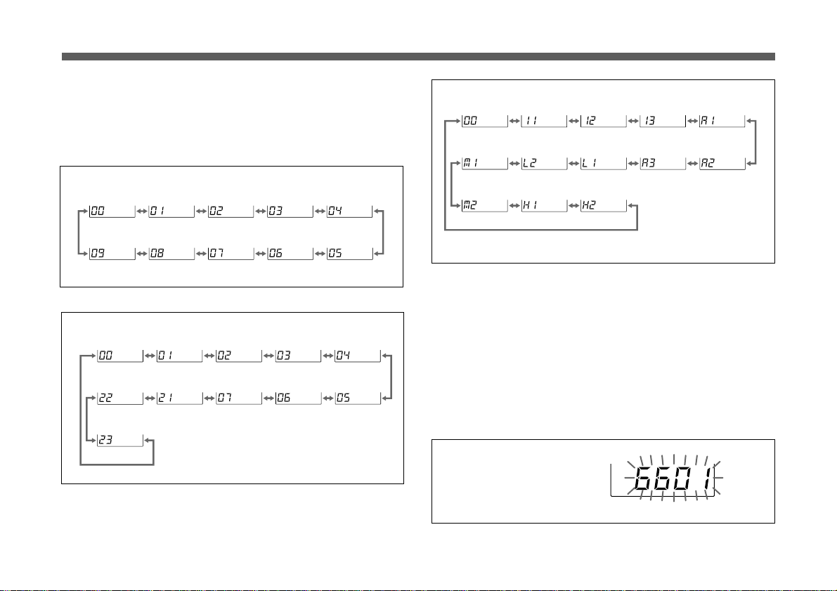
3 Press the + or – button to select the group.
Pressing the + button cyclically changes the groups in
(Continued)
9
(GB)
Settings
numerical order and pressing the – button changes them
in the reverse order.
Press and hold down the button to continuously change
the display.
Model available in USA
Model available in Europe (CE21)
Model available in Australia
If no buttons are pressed for 5 seconds, the group
selection mode is automatically cancelled and the lowest
frequency channel in the group selected at that time is
displayed.
For Group 00, however, the channel previously set in
Group 00 appears.
4
When the desired group is displayed, press the CH button.
The tuner goes to the channel selection mode and the
channel number flashes.
Channel selection
mode
Display example for U66 model
10
(GB)
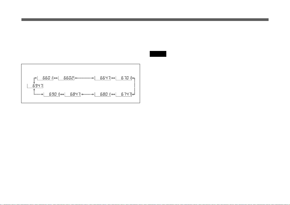
5 Press the + or – button to select the channel.
Pressing the + button cyclically changes the channels of
the group selected in step 3 in the listed order in the
respective table in the “Wireless Microphone System
Frequency List ” supplied with this manual.
Pressing the – button changes them in the reverse order.
When the group 00 is selectedfor U66 model
When you reach the last channel in the group, press the +
button to return to the first channel in the group.
Likewise, press the – button to go from the first channel
to the last channel.
6 After the desired channel is displayed, leave the unit for
5 seconds without pressing any buttons.
Channel selection mode is automatically canceled and
the channel shown on the display is set.
Storing the group and channel
The selected group and channel set by the above procedure
are stored in memory when the display stops flashing.
Notes
To eliminate interference or noise, please note the
following.
Do not use two or more wireless microphones or
•
transmitters whose wireless channels are the same.
If there is a TV broadcasting station nearby, to avoid
•
possible interference from its broadcast, do not use that
station’s channel.
The number of wireless channels actually usable in a
•
multi-channel system may be smaller than the normal
capacity of that system if there is interference from TV
broadcasting or other RF signals.
• To operate two or more UHF synthesized wireless
microphones/transmitters using the same wireless channel
of the same group, ensure that the wireless microphones/
1)
transmitters are at least 100 m (330 feet
)
apart as far as
they are installed within sight of each other.
• When using two or more WRR-855A/855Bs, do not
directly put one unit upon the other.
.........................................................................................................................
1) The distance depends on the operating environment and conditions.
11
(GB)

Settings
Interference-check function
Before operating a wireless microphone or transmitter, you
can check for possible interference by using the
interference-check function of this unit. To check the
interference, simultaneously press the + and – buttons in the
channel selection mode (the channel number flashes). The
channels of the selected group are automatically switched
one by one in sequence (this operation is called “scanning”).
Notes
• When the MUTING switch is ON and the unit is not in the
T OFF mode (see page 13), scanning stops and the channel
at that time is selected if a tone signal (32.768 kHz) is
detected in the signal received during scanning.
However, scanning will not stop if a interfering signal
having no tone signal is received.
In this case, check for the interference by observing the RF
input level indicator.
• Scanning is automatically cancelled when all the channels
of the selected group are scanned twice. To cancel
scanning in progress, press any of the operation buttons.
• If an extremely strong signal is received, scanning may
stop at a point other than the actual channel.
Setting and Releasing the T (Tone Squelch) OFF Mode
The WRR-855A/855B has the following three muting
functions, which work in combination.
(1) Muting by RF input level: As sufficient S/N for the
audio output may not be obtained if no RF signal is
received or the RF input level is low, the audio output
can be muted when the RF input level falls below the
selected level.
(2) Tone squelch: The audio output is obtained only when
the tuner receives an RF signal which includes a
specified tone signal. The audio output is muted to
eliminate noise which may be heard when the transmitter
is turned on/off or the tuner receives an interference RF
signal.
(3) Noise squelch: The audio output is muted to eliminate
noise which may be heard when there is such excessive
interference RF signal that the tone squelch does not
work.
Only the muting functions described in (2) can be canceled
by selecting the Tone-squelch OFF (T OFF) mode when
desired. Apply this mode when you use a transmitter with
no specified tone signal.
12
(GB)
Attaching and Connecting to a Betacam
Selecting the T OFF mode
1 Turn the power ON while pressing and holding the GP
and – buttons.
2 On the WRR-855A, release the buttons after the
“HELLO” message appears. On the WRR-855B, release
the buttons after the version number of your tuner (for
example “U66”) appears.
“T OFF” is momentarily displayed and the tuner goes to
the T OFF mode.
The T OFF mode is maintained even when the power is
turned OFF.
Cancelling the T OFF mode
1 Turn the power ON while pressing and holding the GP
and + buttons.
2 On the WRR-855A, release the buttons after the
“HELLO” message appears. On the WRR-855B, release
the buttons after the version number of your tuner
appears.
“T ON” is momentarily displayed and the tuner resumes
the normal status.
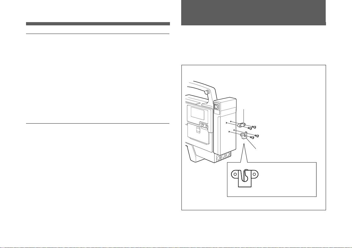
Use the Betacam attachment kit supplied with the BTA-801
Portable Tuner Mount Adapter.
1 Attach the holder and bracket to the Betacam.
Holder
Binding head screws (M3 × 6) (2)
Binding head screws
(M4 × 6) (2)
Bracket
Attach with the slit
facing upward.
13
(GB)
U
H
F
S
Y
N
T
H
E
S
I
Z
E
D
T
U
N
E
R
U
N
I
T
W
R
R
-
8
5
5
S
OUTPUT
AUDIO IN
Attaching and Connecting to a Betacam
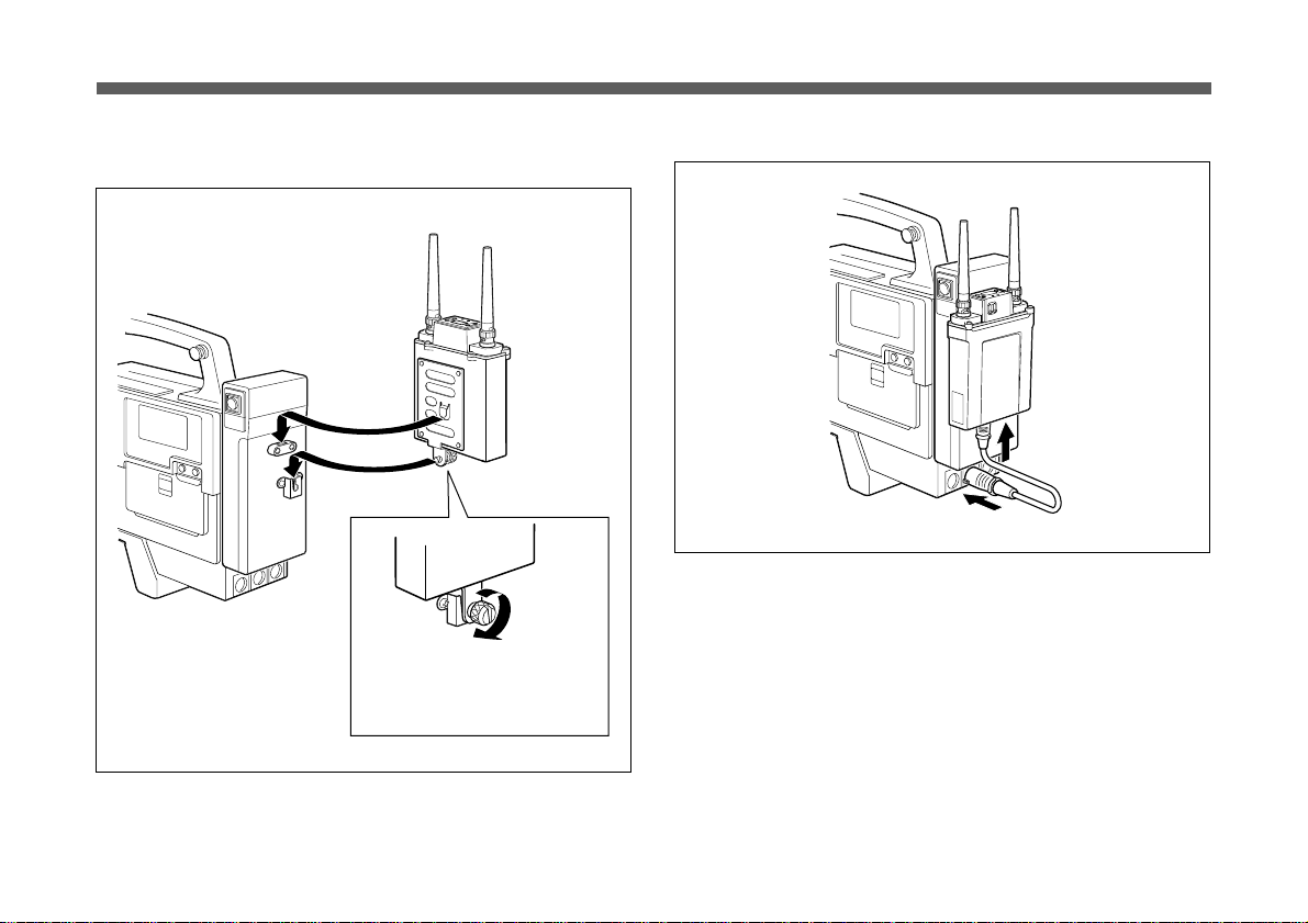
2 Align the attachment plate of the back of the BTA-801
with the holder and bracket.
Press the knob and turn it 90°
in a clockwise manner to
secure.
3 Connect the output cable (optional).
4 Connect the DC power cable supplied with the BTA-801.
For the power cable connection, see page 8.
14
(GB)

Messages on the Display
Specifications
In addition to the normal indications, the following messages
may appear on the liquid-crystal display.
Messages
Err 01
Err 02
Err 03
TONE
T OFF
a) When the tuner is turned on, this message appears after “HELLO”
on the WRR-855A. On the WRR-855B, the message appears
after the version number of your tuner.
Subsequently, the tuner goes to the normal display status.
Contents
An error occurred in
backup memory data.
The PLL synthesized
circuit is in trouble.
The operating voltage
exceeds the allowable
value.
As no tone signal is
available or a tone signal
other than 32.768 kHz is
being received, the audio
signal output is being
muted.
a)
The tuner is set in T OFF
mode.
Measures
Contact your Sony dealer.
Set the tuner to the T OFF
mode (see page 13) to
output the audio signal.
For details, see “Selecting
and Releasing the T (Tone
Squelch) OFF Mode" on
page 12.
Tuner section
Type of reception Space diversity
Circuit system Dual conversion superheterodyne
Receiving frequencies
Model available in USA:
one frequency within a 24 MHz
frequency band selected from 470 to
806 MHz
Model available in Europe:
one frequency within a 24 MHz
frequency band selected from 470 to
862 MHz
Model available in Australia:
Local oscillators
one frequency
1st: Crystal controlled PLL synthesizer
within 792 to 806 MHz
2nd: Crystal oscillator
Antenna connectors BNC-R type (2), 50 ohms
Selectivity 60 dB or more (at ±250 kHz detuned)
Suprious rejection ratio
70 dB or more
Image rejection ratio60 dB or more
Muting level 10 dBµ (ON/OFF selectable)
De-emphasis 50 µs
Frequency response 50 to 15,000 Hz ±3.0 dB
...........................................................................................................................
0 dBµ = 1 µVEMF
0 dBu = 0.775 Vrms
15
(GB)

Specifications
Signal-to-noise ratio
(±5.0 kHz deviation at 1 kHz modulation)
30 dB or more at RF input level
10 dBµ (A-weighted)
60 dB or more at RF input level
60 dBµ (A-weighted)
Distortion 1.0% or less (±40 kHz deviation at
1 kHz modulation)
Tone squelch frequency
32.768 kHz
Output level –40 dBu (±5.0 kHz deviation at 1 kHz
modulation)
Output impedance 25 ohms, unbalanced
Output connector 15-pin D-sub connector (1)
General
Power requirements DC 7 V (supplied from the BTA-801)
Operating voltage DC 6.5 to 9.0 V
Current consumption
200 mA DC or less (at DC 7 V)
Operating temperature
0°C to +50°C (32°F to 122°F)
Storage temperature –20°C to +60°C (–4°F to +140°F)
Dimensions 88 × 118.8 × 31.3 mm (w/h/d)
(31/2 × 43/4 × 11/4 inches)
Mass Approx. 280 g (9.9 oz) with the
supplied antennas attached
Supplied accessories
Antennas (2)
Operating instructions (1)
Wireless Microphone System Frequency List (1)
Optional accessories
Portable Tuner Mount Adapter: BTA-801
Microphone cable (for Audio output cable):
EC-0.5C2-F (XLR-3-11C type ↔ XLR-3-11C type)
EC-0.5C2 (XLR-3-11C type ↔ XLR-3-12C type)
Design and specifications are subject to change without
notice.
16
(GB)

Français
Table des matières
Précautions
Précautions......................................................................... 1
Introduction ....................................................................... 2
Caractéristiques.............................................................. 2
Identification des pièces .................................................... 4
WRR-855A/855B .......................................................... 5
Adaptateur de montage de syntoniseur portable
BTA-801 (en option) ................................................ 6
Préparations ....................................................................... 7
Installation sur un adaptateur de montage
de syntoniseur portable ............................................. 7
Raccordement du câble d’alimentation.......................... 8
Fixation des antennes..................................................... 8
Réglages .............................................................................. 9
Sélection d’un canal....................................................... 9
Régler et quitter le mode T OFF (Silencieux) ............. 12
Fixation sur un caméscope Betacam et raccordements 13
Messages affichés ............................................................. 15
Spécifications.................................................................... 15
En cours de fonctionnement
• Le syntoniseur est conçu pour être utilisé à une
température ambiante de 0°C à 50°C (32°F à 122°F).
Evitez les utilisations prolongées avec une température
excessive ou dans un endroit exposé au soleil, notamment
à l’extérieur, car cela pourrait endommager la finition
extérieure de l’appareil.
N’installez jamais le syntoniseur sur ou à proximité de
sources de chaleur, comme du matériel d’éclairage ou des
amplificateurs.
• Le syntoniseur est conçu pour être portable et pour résister
à l’humidité et à la poussière. Cependant, évitez de
l’utiliser dans des endroits très humides ou très
poussiéreux, car cela pourrait réduire la durée de vie de
l’appareil.
• Pour éviter la dégradation du rapport signal/bruit, n’utilisez
pas le syntoniseur dans des endroits bruyants ou soumis à
des vibrations, par exemple :
– à proximité d’équipements électriques comme des
moteurs, des transformateurs ou des variateurs ;
– à proximité d’équipement d’air conditionné ou dans des
endroits soumis à un flux d’air conditionné direct ;
– à proximité d’un haut-parleur pour une sonorisation
extérieure ;
– dans un endroit où les équipements adjacents pourraient
heurter le syntoniseur.
• Le fait d’allumer ou d’éteindre des lampes peut produire
des interférences électriques sur l’ensemble de la plage de
fréquences.
FR
Français
is
1
(FR)
 Loading...