

Page 1

S
3-800-445-11(1)
UHF Synthesized
Diversity Tuner
Operating Instructions
Before operating the unit, please read this manual
thoroughly and retain it for future reference.
WRR-850A
1996 by Sony Corporation
1
Page 2
Owner’s Record
The model and serial numbers are located at the
rear. Record the serial number in the space
provided below. Refer to these numbers
whenever you call upon your Sony dealer
regarding this product.
Model No. WRR-850A
Serial No. ________________
Notice for customers in Canada:
Use of Sony wireless devices is regulated by
Industry Canada as described in their
Telecommunication Regulatory Circular RSS-123.
A licence is normally required. The local district
office of Industry Canada should therefore be
contacted. When the operation of the device is
within the broadcast band, the licence is issued
on no-interference, no-protection basis with
respect to broadcast signals.
You are cautioned that any changes or
modifications not expressly approved in this
manual could void your authority to operate this
equipment.
WARNING
To prevent fire or shock hazard, do not
expose the unit to rain or moisture.
To avoid electrical shock, do not open the
cabinet. Refer servicing to qualified personnel
only.
Avis pour les clients au Canada:
L’usage des appareils sans-fil Sony est réglé par
l’Industrie Canada comme décrit dans leur Cahier
des Normes Radioélectriques CNR-123. Une
licence est normalement requise. Le bureau de
l’Industrie Canada doit être contacté.
Lorsque l’opération de l’appareil est dans les
limites de la bande de radiodiffusion, la licence
est émanée sur la base de non-interférence, nonprotection avec les signaux de radiodiffusion.
This symbol is intended to alert the user to
presence of uninsulated “dangerous voltage” within the product’s enclosure that
may be of sufficient magnitude to constitute
a risk of electric shock to persons.
This symbol is intended to alert the user to
the presence of important operating and
maintenance (servicing) instructions in the
literature accompanying the appliance.
2
Page 3

Table of Contents
Features ......................................................................................................4
Channel Plan .............................................................................................. 5
Groups, Channels and Frequencies ........................................................5
42 Channel System Plan.........................................................................9
Precautions ............................................................................................... 10
Location of Parts and Controls ..............................................................11
Front Panel ...........................................................................................11
Display..................................................................................................12
Rear Panel.............................................................................................13
Connections ..............................................................................................14
Basic Connections ................................................................................14
Multichannel Mode ..............................................................................15
Installation................................................................................................16
Installation of Receivers and Antennas ................................................16
Notes on Antenna Installation ..............................................................17
System Setup ............................................................................................18
System Configuration...........................................................................18
Settings......................................................................................................22
Selecting the Reception Channel.......................................................... 22
Setting the Muting Level ......................................................................25
Setting the Output Level.......................................................................27
Setting the Tuner Unit Number ............................................................27
Operation..................................................................................................28
Rack Mounting ........................................................................................30
Removing the Mounting Brackets........................................................31
Dimensions...........................................................................................31
Error Messages ........................................................................................ 32
Specifications............................................................................................33
3
Page 4

Features
The WRR-850A is a high-performance tuner for the 800-MHz-band Sony
UHF wireless microphone system which uses the frequency bands
allocated for UHF TV broadcasting. This tuner enables application of
multiple channels over unused television channels through the use of the
built-in Sony original channel plan.
Phase Locked Loop (PLL) synthesized system
The unit has a refined phase locked loop (PLL) synthesizer circuit and
covers two UHF TV channels. It operates on 94 channels over a 12-MHz
frequency.
Built-in wireless channel plan for simultaneous
multichannel operation
The WRR-850A has many preprogrammed, easily settable channels in a
simultaneous multichannel operation. One group allows setting of 94
channels. The unit also has six preset groups of channels, each of which
permits simultaneous operation of 8, 11, 13, or 19 channels without the
effects of intermodulation. There is also a channel plan for 42 channel
simultaneous operation using the 6 TV bands on UHF TV channels 64 to
69.
Twin tuners
The WRR-850A has two tuner units. You can set the tuners to different
channels and still operate both at the same time.
Versatile display
A large liquid-crystal display provides a variety of information, including
the levels of the reception channels, RF information and transmitter battery
condition.
Space diversity reception system
The WRR-850A provides stable signal reception with minimum dropout.
Adjustable muting level
You can select the muting level (15 dBµ, 25 dBµ and 35 dBµ) to meet your
specific needs.
Tone squelch circuit for noise elimination
A built-in squelch circuit eliminates noise and signal interference when the
unit is in signal reception standby mode.
Compander system
A compander (compressor/expander) system enables stabilized wireless
transmission over a wide dynamic range.
Output monitoring
You can monitor the audio output using headphones. The level is
adjustable.
1U-size EIA rack mount
4
The unit can be mounted in an EIA-standard 19-inch rack (1U size).
Page 5

Channel Plan
Groups, Channels and Frequencies
The unit stores 11 groups of selectable channels: groups 00
(94 channels), 11 (11 ch.), 12 (8 ch.), 13 (8 ch.), A1 (19 ch.),
A2 (13 ch.), A3 (13 ch.), L1 (7 ch.), L2 (7 ch.), H1 (7 ch.),
and H2 (7 ch.). Channel groups other than group 00 are
designed so that all channels of one group can be used
simultaneously within the same UHF wireless microphone
system without causing intermodulation. It is therefore
recommended that you usually use a channel group other than
group 00 unless the use of group 00 is specifically necessary.
The following pages explain the purpose of each group, and
give the channel-frequency assignment table for each group.
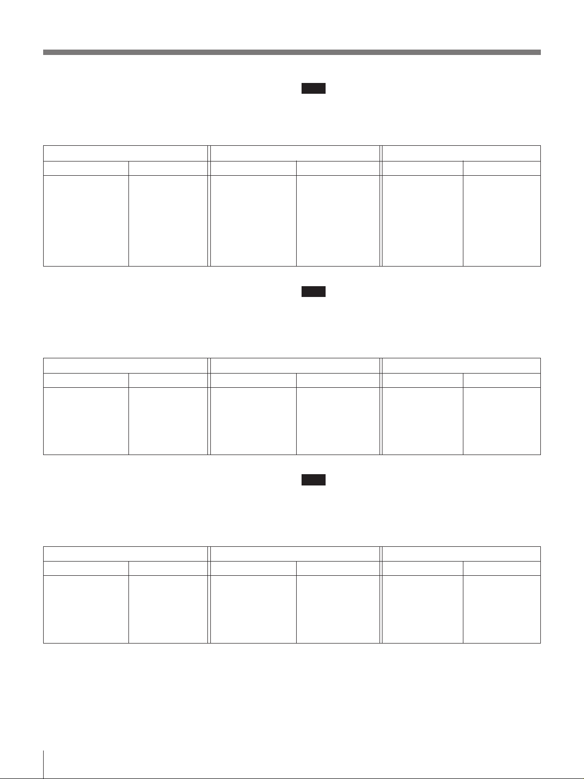
Group 00 (to receive all 94 channels)
This group receives all 94 wireless microphone channels
selected at 125-kHz intervals in a frequency band assigned
to a WRR-850A combination.
Note
When using more than one channel from group 00
Notes
• Each “wireless channel” is represented by a 2-digit TV
channel number and a 2-digit number, for example: 68-23.
• The channels in each group other than group 00 can be
used simultaneously.
• When operating two or more UHF wireless microphone
systems using channels in different groups, ensure that the
systems are at least 100 m (330 feet) apart from each other.
(The same applies also when using channels in a group if
the different UHF wireless microphone systems are
installed where they are within sight of each other.)
• If there is a TV broadcasting station nearby, to avoid
possible interference with broadcasting, do not use that
station’s channel.
• The number of wireless microphone channels actually
usable in a multi-channel system may be smaller than the
normal capacity of that system if there is interference from
TV broadcasting or other RF signals.
simultaneously, avoid selecting adjacent channels or
channels at uniform intervals.
WRR-850A (64) WRR-850A (66) WRR-850A (68)
Channel Frequency Channel Frequency Channel Frequency Channel Frequency Channel Frequency Channel Frequency
64-01
64-02
64-03
64-04
64-05
64-06
64-07
64-08
64-09
64-10
64-11
64-12
64-13
64-14
64-15
64-16
64-17
64-18
64-19
64-20
64-21
64-22
64-23
64-24
64-25
64-26
64-27
64-28
64-29
64-30
64-31
64-32
64-33
64-34
64-35
64-36
64-37
64-38
64-39
64-40
64-41
64-42
64-43
64-44
64-45
64-46
64-47
770.125
770.250
770.375
770.500
770.625
770.750
770.875
771.000
771.125
771.250
771.375
771.500
771.625
771.750
771.875
772.000
772.125
772.250
772.375
772.500
772.625
772.750
772.875
773.000
773.125
773.250
773.375
773.500
773.625
773.750
773.875
774.000
774.125
774.250
774.375
774.500
774.625
774.750
774.875
775.000
775.125
775.250
775.375
775.500
775.625
775.750
775.875
65-01
65-02
65-03
65-04
65-05
65-06
65-07
65-08
65-09
65-10
65-11
65-12
65-13
65-14
65-15
65-16
65-17
65-18
65-19
65-20
65-21
65-22
65-23
65-24
65-25
65-26
65-27
65-28
65-29
65-30
65-31
65-32
65-33
65-34
65-35
65-36
65-37
65-38
65-39
65-40
65-41
65-42
65-43
65-44
65-45
65-46
65-47
776.125
776.250
776.375
776.500
776.625
776.750
776.875
777.000
777.125
777.250
777.375
777.500
777.625
777.750
777.875
778.000
778.125
778.250
778.375
778.500
778.625
778.750
778.875
779.000
779.125
779.250
779.375
779.500
779.625
779.750
779.875
780.000
780.125
780.250
780.375
780.500
780.625
780.750
780.875
781.000
781.125
781.250
781.375
781.500
781.625
781.750
781.875
66-01
66-02
66-03
66-04
66-05
66-06
66-07
66-08
66-09
66-10
66-11
66-12
66-13
66-14
66-15
66-16
66-17
66-18
66-19
66-20
66-21
66-22
66-23
66-24
66-25
66-26
66-27
66-28
66-29
66-30
66-31
66-32
66-33
66-34
66-35
66-36
66-37
66-38
66-39
66-40
66-41
66-42
66-43
66-44
66-45
66-46
66-47
782.125
782.250
782.375
782.500
782.625
782.750
782.875
783.000
783.125
783.250
783.375
783.500
783.625
783.750
783.875
784.000
784.125
784.250
784.375
784.500
784.625
784.750
784.875
785.000
785.125
785.250
785.375
785.500
785.625
785.750
785.875
786.000
786.125
786.250
786.375
786.500
786.625
786.750
786.875
787.000
787.125
787.250
787.375
787.500
787.625
787.750
787.875
67-01
67-02
67-03
67-04
67-05
67-06
67-07
67-08
67-09
67-10
67-11
67-12
67-13
67-14
67-15
67-16
67-17
67-18
67-19
67-20
67-21
67-22
67-23
67-24
67-25
67-26
67-27
67-28
67-29
67-30
67-31
67-32
67-33
67-34
67-35
67-36
67-37
67-38
67-39
67-40
67-41
67-42
67-43
67-44
67-45
67-46
67-47
788.125
788.250
788.375
788.500
788.625
788.750
788.875
789.000
789.125
789.250
789.375
789.500
789.625
789.750
789.875
790.000
790.125
790.250
790.375
790.500
790.625
790.750
790.875
791.000
791.125
791.250
791.375
791.500
791.625
791.750
791.875
792.000
792.125
792.250
792.375
792.500
792.625
792.750
792.875
793.000
793.125
793.250
793.375
793.500
793.625
793.750
793.875
68-01
68-02
68-03
68-04
68-05
68-06
68-07
68-08
68-09
68-10
68-11
68-12
68-13
68-14
68-15
68-16
68-17
68-18
68-19
68-20
68-21
68-22
68-23
68-24
68-25
68-26
68-27
68-28
68-29
68-30
68-31
68-32
68-33
68-34
68-35
68-36
68-37
68-38
68-39
68-40
68-41
68-42
68-43
68-44
68-45
68-46
68-47
794.125
794.250
794.375
794.500
794.625
794.750
794.875
795.000
795.125
795.250
795.375
795.500
795.625
795.750
795.875
796.000
796.125
796.250
796.375
796.500
796.625
796.750
796.875
797.000
797.125
797.250
797.375
797.500
797.625
797.750
797.875
798.000
798.125
798.250
798.375
798.500
798.625
798.750
798.875
799.000
799.125
799.250
799.375
799.500
799.625
799.750
799.875
Frequency (in MHz)
69-01
69-02
69-03
69-04
69-05
69-06
69-07
69-08
69-09
69-10
69-11
69-12
69-13
69-14
69-15
69-16
69-17
69-18
69-19
69-20
69-21
69-22
69-23
69-24
69-25
69-26
69-27
69-28
69-29
69-30
69-31
69-32
69-33
69-34
69-35
69-36
69-37
69-38
69-39
69-40
69-41
69-42
69-43
69-44
69-45
69-46
69-47
800.125
800.250
800.375
800.500
800.625
800.750
800.875
801.000
801.125
801.250
801.375
801.500
801.625
801.750
801.875
802.000
802.125
802.250
802.375
802.500
802.625
802.750
802.875
803.000
803.125
803.250
803.375
803.500
803.625
803.750
803.875
804.000
804.125
804.250
804.375
804.500
804.625
804.750
804.875
805.000
805.125
805.250
805.375
805.500
805.625
805.750
805.875
5
Page 6
Channel Plan
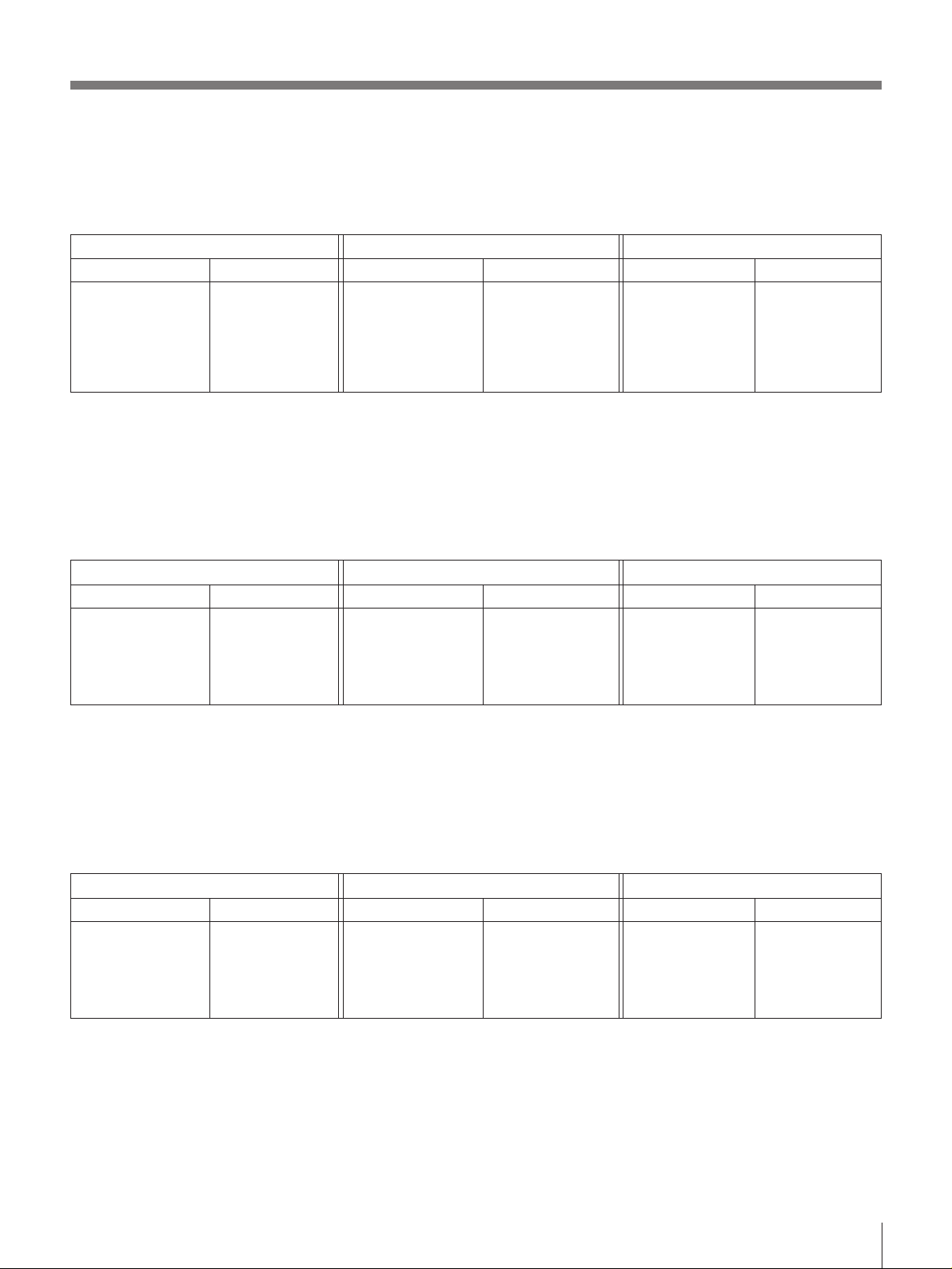
Group 11 (for an 11-channel system)
This group is used to simultaneously receive up to 11
wireless microphone channels selected in the frequency
band assigned to a WRR-850A combination.
WRR-850A (64) WRR-850A (66) WRR-850A (68)
Channel
64-05
64-14
64-25
64-41
64-47
65-12
65-16
65-30
65-37
65-40
65-42
Frequency
770.625
771.750
773.125
775.125
775.875
777.500
778.000
779.750
780.625
781.000
781.250
Channel
66-05
66-14
66-25
66-41
66-47
67-12
67-16
67-30
67-37
67-40
67-42
Group 12 (for an 8-channel system using odd-numbered
TV channels)
This group is used to simultaneously receive up to eight
wireless microphone channels selected in the frequency
band of the odd-numbered TV channel assigned to a WRR850A combination.
WRR-850A (64) WRR-850A (66) WRR-850A (68)
Channel
65-01
65-05
65-11
65-25
65-28
65-36
65-41
65-43
Frequency
776.125
776.625
777.375
779.125
779.500
780.500
781.125
781.375
Channel
67-01
67-05
67-11
67-25
67-28
67-36
67-41
67-43
Note
In a place where an 11-channel system composed of a
particular WRR-850A combination is used, you cannot
simultaneously use another 11-channel system composed of
a different WRR-850A combination.
Note
Frequency
782.625
783.750
785.125
787.125
787.875
789.500
790.000
791.750
792.625
793.000
793.250
Channel
68-05
68-14
68-25
68-41
68-47
69-12
69-16
69-30
69-37
69-40
69-42
Frequency (in MHz)
Frequency
794.625
795.750
797.125
799.125
799.875
801.500
802.000
803.750
804.625
805.000
805.250
In a place where an 8-channel system composed of a
particular WRR-850A combination is used, you cannot
simultaneously use another 8-channel system composed of a
different WRR-850A combination.
Frequency (in MHz)
Frequency
788.125
788.625
789.375
791.125
791.500
792.500
793.125
793.375
Channel
69-01
69-05
69-11
69-25
69-28
69-36
69-41
69-43
Frequency
800.125
800.625
801.375
803.125
803.500
804.500
805.125
805.375
Group 13 (for an 8-channel system using even-numbered
TV channels)
This group is used to simultaneously receive up to eight
wireless microphone channels selected in the frequency
band of the even-numbered TV channel assigned to a WRR850A combination.
WRR-850A (64) WRR-850A (66) WRR-850A (68)
Channel
64-03
64-13
64-18
64-26
64-37
64-40
64-44
64-46
Frequency
770.375
771.625
772.250
773.250
774.625
775.000
775.500
775.750
Channel
66-03
66-13
66-18
66-26
66-37
66-40
66-44
66-46
6
Note
In a place where an 8-channel system composed of a
particular WRR-850A combination is used, you cannot
simultaneously use another 8-channel system composed of a
different WRR-850A combination.
Frequency (in MHz)
Frequency
782.375
783.625
784.250
785.250
786.625
787.000
787.500
787.750
Channel
68-03
68-13
68-18
68-26
68-37
68-40
68-44
68-46
Frequency
794.375
795.625
796.250
797.250
798.625
799.000
799.500
799.750
Page 7
Group A1 (for a 19-channel system)
This group is used to simultaneously receive up to 19
channels selected in the overall frequency band of 6 TV
channels receivable by three types of tuner combinations:
WRR-850A (64), WRR-850A (66) and WRR-850A (68).
WRR-850A (64) WRR-850A (66) WRR-850A (68)
Channel
64-05
64-12
64-15
65-24
65-33
—
—
—
Frequency
770.625
771.500
771.875
779.000
780.125
—
—
—
Channel
66-02
66-24
66-29
67-16
67-18
67-39
—
—
Group A2 (for a 13-channel system using odd-numbered
TV channels)
This group is used to simultaneously receive up to 13
wireless microphone channels selected in the frequency
bands of the odd-numbered TV channels receivable by three
types of tuner combinations: WRR-850A (64), WRR-850A
(66) and WRR-850A (68).
WRR-850A (64) WRR-850A (66) WRR-850A (68)
Channel
65-02
65-19
65-43
—
—
—
—
Frequency
776.250
778.375
781.375
—
—
—
—
Channel
67-07
67-33
67-45
—
—
—
—
Frequency
782.250
785.000
785.625
790.000
790.250
792.875
—
—
Frequency
788.875
792.125
793.625
—
—
—
—
Channel
68-06
68-20
68-24
68-40
69-04
69-17
69-23
69-47
Channel
69-11
69-22
69-30
69-36
69-40
69-43
69-45
Frequency (in MHz)
Frequency
794.750
796.500
797.000
799.000
800.500
802.125
802.875
805.875
Frequency (in MHz)
Frequency
801.375
802.750
803.750
804.500
805.000
805.375
805.625
Group A3 (for a 13-channel system using evennumbered TV channels)
This group is used to simultaneously receive up to 13
wireless microphone channels selected in the frequency
bands of even-numbered TV channels receivable by three
types of tuner combinations: WRR-850A (64), WRR-850A
(66) and WRR-850A (68).
WRR-850A (64) WRR-850A (66) WRR-850A (68)
Channel
64-01
64-18
64-42
—
—
—
—
Frequency
770.125
772.250
775.250
—
—
—
—
Channel
66-06
66-32
66-44
—
—
—
—
Frequency
782.750
786.000
787.500
—
—
—
—
Channel
68-10
68-21
68-29
68-35
68-39
68-42
68-44
Frequency (in MHz)
Frequency
795.250
796.625
797.625
798.375
798.875
799.250
799.500
7
Page 8

Channel Plan
Group L1 (for a 7-channel system using even-numbered
TV channels)
This group is used to simultaniously receive up to 7 wireless
microphones.
WRR-850A (64) WRR-850A (66) WRR-850A (68)
Channel
64-09
64-11
64-19
64-25
64-30
64-34
64-37
Group L2 (for a 7-channel system using even-numbered
TV channels)
This group is used to simultaniously receive up to 7 wireless
microphones.
WRR-850A (64) WRR-850A (66) WRR-850A (68)
Channel
64-10
64-13
64-17
64-22
64-28
64-36
64-38
Frequency
771.125
771.375
772.375
773.125
773.750
774.250
774.625
Frequency
771.250
771.625
772.125
772.750
773.500
774.500
774.750
Channel
66-09
66-11
66-19
66-25
66-30
66-34
66-37
Channel
66-10
66-13
66-17
66-22
66-28
66-36
66-38
Frequency
783.125
783.375
784.375
785.125
785.750
786.250
786.625
Frequency
783.250
783.625
784.125
784.750
785.500
786.500
786.750
Channel
68-09
68-11
68-19
68-25
68-30
68-34
68-37
Channel
68-10
68-13
68-17
68-22
68-28
68-36
68-38
Frequency (in MHz)
Frequency
795.125
795.375
796.375
797.125
797.750
798.250
798.625
Frequency (in MHz)
Frequency
795.250
795.625
796.125
796.750
797.500
798.500
798.750
Group H1 (for a 7-channel system using odd-numbered
TV channels)
This group is used to simultaniously receive up to 7 wireless
microphones.
WRR-850A (64) WRR-850A (66) WRR-850A (68)
Channel
65-09
65-11
65-19
65-25
65-30
65-34
65-37
Frequency
777.125
777.375
778.375
779.125
779.750
780.250
780.625
Channel
67-09
67-11
67-19
67-25
67-30
67-34
67-37
Group H2 (for a 7-channel system using odd-numbered
TV channels)
This group is used to simultaniously receive up to 7 wireless
microphones.
WRR-850A (64) WRR-850A (66) WRR-850A (68)
Channel
65-10
65-13
65-17
65-22
65-28
65-36
65-38
Frequency
777.250
777.625
778.125
778.750
779.500
780.500
780.750
Channel
67-10
67-13
67-17
67-22
67-28
67-36
67-38
Frequency
789.125
789.375
790.375
791.125
791.750
792.250
792.625
Frequency
789.250
789.625
790.125
790.750
791.500
792.500
792.750
Channel
69-09
69-11
69-19
69-25
69-30
69-34
69-37
Channel
69-10
69-13
69-17
69-22
69-28
69-36
69-38
Frequency (in MHz)
Frequency
801.125
801.375
802.375
803.125
803.750
804.250
804.625
Frequency (in MHz)
Frequency
801.250
801.625
802.125
802.750
803.500
804.500
804.750
8
Page 9
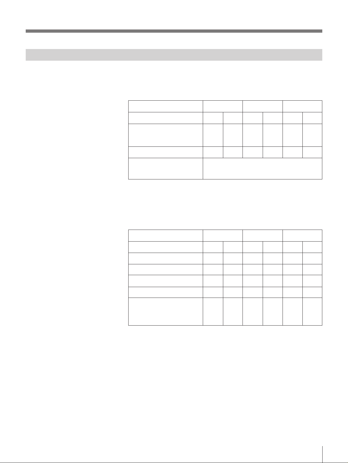
42 Channel System Plan
By combining groups L1 or L2 and H1 or H2 for models 64, 66 and 68 it
is possible to operate 42 channels simultaniously. When operating 42
channels simulaniously, you will need both the WD-820A and the WD880A antenna dividers.
TV Channel
Group name
Number of channels
Number of simultaniously
operable channels when models
64,66 and 68 are used together.
WRR-850A (64)
64
L1
or
L2
7
65
H1
or
H2
7
WRR-850A (66)
66
L1
or
L2
7
42
67
H1
or
H2
7
WRR-850A (68)
68
L1
or
L2
7
• If the TV channel number is even, select group L1 or L2; if it is odd, select
group H1 or H2.
An example of group combination
You can select either group for a TV channel regardless of the group
setting for other TV channels.
TV Channel
Group Combination Example 1
Example 2
WRR-850A (64)
64
L1
L2
65
H1
H2
WRR-850A (66)
66
L1
L2
67
H1
H2
WRR-850A (68)
68
L1
L2
69
H1
or
H2
7
69
H1
H2
Example 3
Example 4
•
•
•
•
L1
L1
H2
H1
•
•
•
•
•
•
•
•
L1
L2
H2
H2
•
•
•
•
•
•
•
•
L1
L2
•
•
•
•
• For further information on group settings, see “Example of 42-Channel
receiving system” on page 21.
H2
H1
•
•
•
•
9
Page 10

Precautions
• The tuner must be used within a temperature range of 0°C to +50°C
(+32°F to +122°F). Avoid using the unit for extended periods at
extremely high temperatures or placing it in direct sunlight, as this may
damage the finish of the case. Never install the tuner on or near a heat
source, such as lighting equipment or power amplifiers.
• If you install the tuner in a rack, be sure that the rack is adequately
ventilated; inadequate rack ventilation may lead to overheating
problems.
• If the tuner is used in an environment that is humid, dusty or susceptible
to harmful gas, clean the connectors and the surface after use. If used in
such an environment for an extended period, the tuner life may be
shortened.
• Do not install the tuner near electrical equipment, such as motors,
transformers, or dimmers, since this may incur magnetic induction.
• Switching lights on or off may produce electrical interference over the
wider frequency range. Position the tuner and the wireless microphones
so that interference is minimized.
• To avoid degradation of the signal-to-noise ratio, do not use the tuner in
noisy places or in locations subject to noise or vibration, such as the
following:
— near electrical equipment, such as motors or transformers
— near air conditioning equipment or places subject to direct air flow
from an air conditioner
— near public address loudspeakers
— where adjacent equipment might knock against the tuner
Install the tuner as far as possible from sources of interference and, if
needed, provide shock absorbent material.
• Clean the tuner with a dry, soft cloth. Never use thinner, benzene,
alcohol or any other chemicals, since these may damage the finish.
10
Page 11
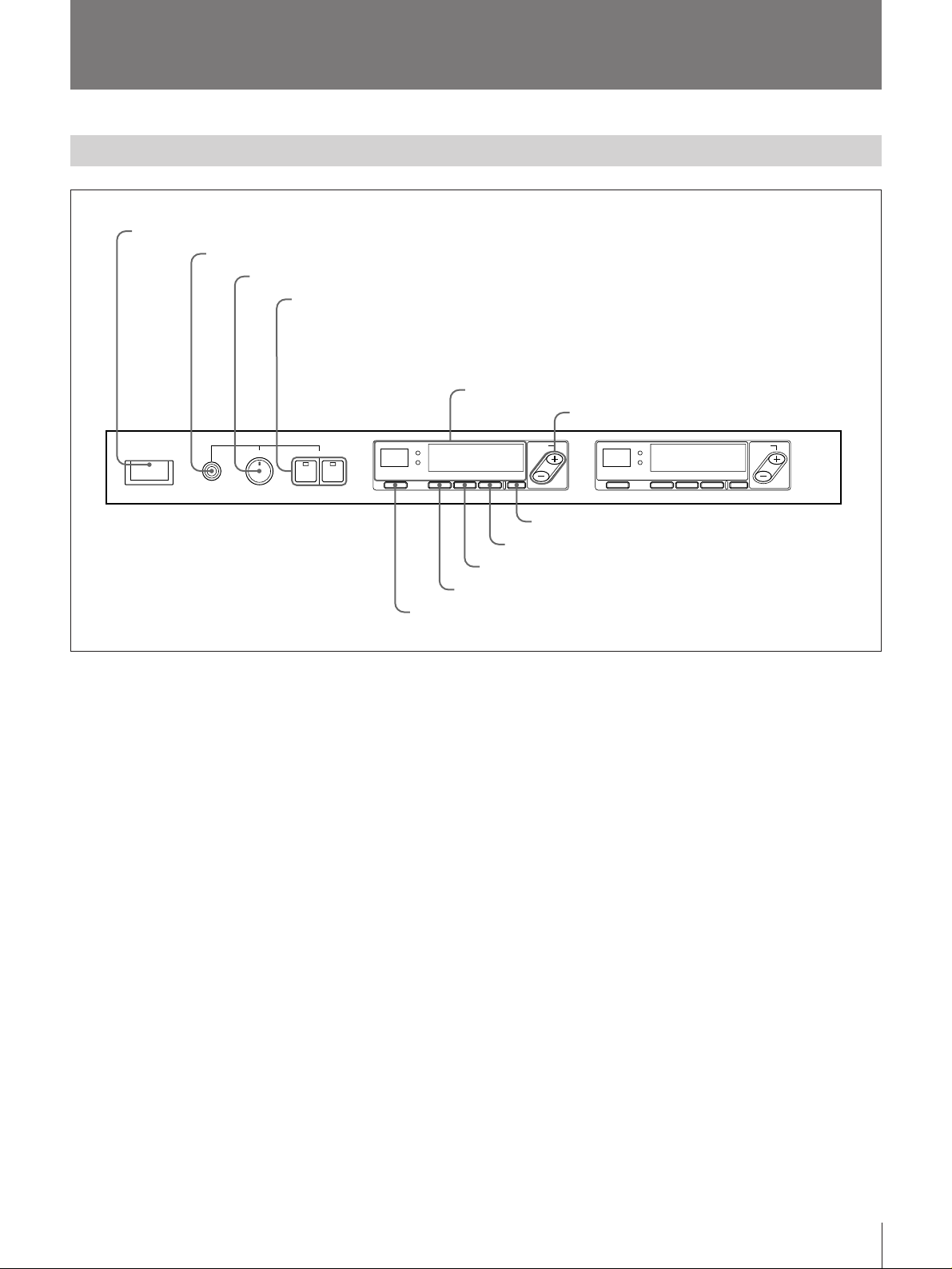
Location of Parts and Controls
Front Panel
1 POWER switch
2 MONITOR jack
3 MONITOR LEVEL control
4 MONITOR switches and indicators
5 Display
6 FREQ +/– buttons
S
POWER
ØON øOFF
MONITOR
MIN MAX
12LEVEL
12
RF
AF
!¡ NO. button
1 POWER switch
Turns the power ON and OFF.
2 MONITOR jack
Connects to headphones to enable monitoring of the
output signal.
3 MONITOR LEVEL control
Adjusts the volume of the headphones connected to the
MONITOR jack.
4 MONITOR switches and indicators
Selects tuner unit 1 or 2 for monitoring. The indicator
below the number of the selected tuner lights.
FREQ
OUTPUT
CHGPMUTINGNO.
LEVEL
7 OUTPUT LEVEL button
8 CH button
9 GP button
0 MUTING button
RF
AF
FREQ
OUTPUT
CHGPMUTINGNO.
LEVEL
UHF SYNTHESIZED DIVERSITY TUNER WRR-850
The FREQ + button toggles between the CH indication
and the frequency indication.
7 OUTPUT LEVEL button
Sets the output level (–20 dBm or –58 dBm).
8 CH (channel) button
Changes the channel in the same group.
9 GP (group) button
Changes the group of the reception channel.
0 MUTING button
Sets the muting level.
Tuner unit 1
5 Display
After you turn on the power, the message “64
HELLO”, “66 HELLO” or “68 HELLO”appears,
depending on the model. When the message
disappears, the tuner changes to normal display mode.
6 FREQ (frequency) +/– buttons
Sets a reception channel with a press on the NO.
button, MUTING button, GP button, CH button, and
OUTPUT LEVEL button.
!¡ NO. (number) button
Sets the tuner unit number.
Tuner unit 2
The buttons for tuner unit 2 have the same functions
as those for tuner unit 1.
11
Page 12

Location of Parts and Controls
Display
1 Number indicator
2 RF lamp
3 RF indicator
4 AF indicator
5 Battery indicator
6 Output level indicator
RF
88
1 Number indicator
Shows the number (1 to 99) that has been assigned to
the tuner unit.
2 RF (radio frequency) lamp
Lights when the antenna reception is optimal.
3 RF (radio frequency input level) indicator
Shows the strength of the input signal. The diversity
changeover is displayed when either a or b is lit.
Indicator
Level
4 AF (audio frequency) indicator
Lights when an audio signal greater than the reference
level is output.
5 Battery indicator
Indicates the condition of the wireless microphone
transmitter batteries. The battery indicator and the
number indicator start flashing about one hour before
the transmitter batteries go flat.
more than
15 dBµ
more than
25 dBµ
AF
9 AF lamp
more than
35 dBµ
a
b
OFF
888.8888
11 1
8 MUTING indicator
more than
45 dBµ
–20 dBm
–58 dBm
MHz
7 GP/CH indicator
Note
The battery and number indicators only flash when the
unit is used with certain transmitters, such as the
WRT-860A. For details on compatible transmitters,
see the operating instructions of the transmitter.
6 Output level indicator
Shows the output reference level.
7 GP/CH (group/channel) indicator
Shows the reception channel group and respective
channel number.
Each time the FREQ + button is pressed, this indicator
switches between showing the reception channel
frequency and the channel number.
8 MUTING indicator
OFF
Shows the muting level or
For details, see “Setting the Muting Level” on page 25.
9 AF (audio frequency) lamp
Lights when an audio signal greater than the reference
level is output.
.
12
Page 13

Rear Panel
1 ANTENNA A, B IN / DC 9 V OUT connectors
2 TUNER OUTPUT connectors
3 REMOTE connector
4 AC power output connector
DO 9V OUT
IN
ANTENNA B
DO 9V OUT
IN
ANTENNA A
12
TUNER OUTPUT
1 ANTENNA A, B IN / DC 9 V OUT (antenna A, B
input/DC power output) connectors (BNC type)
Connects to an AN-820A UHF Antenna (A/B) for
diversity reception.
If an antenna is connected directly to the tuner without
connecting with an antenna divider such as the WD820A, DC 9 V is supplied to the antenna’s internal
booster.
Note
Never short-circuit this connector.
2 TUNER OUTPUT (tuner sound output)
connectors (XLR, 3-pin, male)
Supplies audio signals. You can connect this to the
microphone input connector or the sound input
connector of a mixer, tape recorder, or similar
equipment.
⁄ AC IN
REMOTE (15PIN)
5 AC IN connector
3 REMOTE connector (D-sub, 15-pin)
Connects to a display unit (not supplied) that shows
the numbers for 12 channels and is equipped with an
AF lamp and an RF lamp.
4 AC power output connector
Supplies a maximum of 300 W power to a peripheral
piece of equipment, regardless of whether the POWER
switch is set to ON or OFF.
5 AC IN connector
Connects to an AC power source with the supplied AC
power cable.
2
1
3
1: GND
2: HOT
3: COLD
13
Page 14

Connections
Basic Connections
AN-820A UHF antenna
Antenna B Antenna A
DO 12V OUT
ANTENNA B
DO 12V OUT
IN
IN
ANTENNA A
12
TUNER OUTPUT
Note
Make sure to use a pair of antennas.
WRR-850A
⁄ AC IN
REMOTE (15PIN)
to AC power
to input connector of
a mixer, amplifier, etc.
Once you have made all the connections, use the plus/minus (+/–) buttons
and the OUTPUT LEVEL button to set the reference level of the TUNER
OUTPUT connectors in accordance with the input level of the connected
equipment (mixer, amplifier, etc.).
For details on the reference level setting, see “Setting the Output Level”
on page 27.
14
Page 15

Multichannel Mode
Connect the signal output connectors of each tuner directly to the mixer.
When the tuner is in the multichannel mode, you can set up the mixer for a
variety of operations, such as allocating channels for particular tasks,
limiting the number of microphones used, operating microphones
separately, etc.
In addition to the connections below, you can combine the WRR-850A
tuner with tuners WRR-820A or WRR-840A.
Example of using
four antennas
AN-820A
WD-820A
WD-820A
50-ohm BNC terminators
WRR-850A
WRR-850A
WRR-850A
WRR-850A
WRR-850A
WRR-850A
50-ohm BNC
terminators
15
Page 16

Installation
Installation of Receivers and Antennas
• Small hall with a stage width of 10 meters (33 feet): Install an antenna on both sides of the stage.
• Large hall with a stage width of 15 meters (50 feet) or larger: Install two antennas parallelly (1 to 2 meters [3
to 6 2/3 feet] apart) on the side of the stage closest to the sound control room.
Setup in halls where the sound control room is behind the seating area
Install the antennas on one side
of the stage with the receiver in
the sound control room.
Coaxial cable
Antennas
Sound control room
Receiver unit
1
/3
Setup in halls where the sound control room is behind the seating area and far from the stage
Install the receiver unit close to
the antennas at the side of the
stage to minimize the length of
the antenna (coaxial) cable.
Audio cable
Receiver unit
Antennas
Sound control room
16
Page 17

Setup in halls where the sound control room is at the side of the stage
Sound control room
Receiver unit
Antenna
Notes on Antenna Installation
• Use a pair of antennas. Separate them by 1 to 2
1
meters (3
/3 to 6 2/3 feet). Mount the antennas so that
a wireless microphone or transmitter can transmit
signals directly to the antennas.
• Do not install the antennas in the following
locations:
– inside the ceiling or walls
– near windows, metal boards, or electric equipment
(lighting fixtures, motors, elevators, breakers, etc.)
electronic equipment (computers, dimmers,
televisions, TV cameras, etc.)
– where people or other equipment might interfere
with them
Separate the antennas by 1 to 2
meters (3 1/3 to 6 2/3 feet).
• The recommended coaxial cable for connecting the
antennas to the tuner and antenna divider is a 5D-2V
(50 ohm or higher). You can also use a 5C-2V (75
ohm or higher).
Signal loss: 5D-2V 50 m: 12.5 dB
100 m: 25 dB
5C-2V 50 m: 13.5 dB
100 m: 27 dB
• The coaxial cable should be as short as possible. The
signal loss increases as the cable length increases,
which has a greater impact than the difference
between 50 ohms and 75 ohms.
Mount the antennas more than 10 centimeters
(4 in.) away from the ceiling or an adjacent wall.
Mount the antennas about half way
between the floor and the ceiling or
at about 5 meters (16 ft. 8 in.) in
height.
Mount the antennas as far as
possible from windows to prevent
interference from outside.
Mount the antennas as far as
possible from electric equipment
(e.g., elevators, computers, etc.) to
prevent radio wave interference.
17
Page 18

System Setup
System Configuration
Connection of tuners in series allows for 19 channel
simultaneous operation. If the WD-880A antenna
divider is used, a maximum of 42 channels become
Use a pair of antennas. Do not operate multiple
wireless microphones or transmitters on the same
channel.
available.
When using two channels When using four channels
AN-820A
WRR-850A
WD-820A
WRR-850A
When using six channels
AN-820A
AN-820A
for four antennas
for four antennas
WD-820A
WRR-850A
When combining with an existing system
AN-820A
for four antennas
WD-820A
WRR-820A
WRR-840A
WRR-850A
When using 19 channels
AN-820A
for four antennas
WD-820A
WRR-850A
18
Page 19

Example of 11-channel receiving system (using Group 11)
AN-820A AN-820A
Cascade connection
WD-820A
WRR-850A
Example of 8-channel receiving system (using Group 12 or 13)
AN-820A AN-820A
WD-820A
WD-820A
WRR-850A
WRR-850A
19
Page 20

Installation
Example of 13-channel receiving system (using Group A2 or A3)
AN-820A
Cascade
WD-820A WD-820A
WRR-850A (64)
WRR-850A (68)
WRR-850A (66)
TV Channel 64: 3 channels +
TV Channel 66: 3 channels
TV Channel 64: 3 channels
+
TV Channel 66: 3 channels
+
TV Channel 68: 7 channels
AN-820A
TV Channel 68: 7 channels
Example of 19-channel receiving system (using Group A1)
AN-820A
Cascade connection Cascade connection
WD-820A
WRR850A (64)
WRR850A (66)
TV Channel 64: 5 channels +
TV Channel 66: 2 channels
WD-820A
WRR850A (66)
WRR850A (68)
TV Channel 66: 4 channels +
TV Channel 68: 4 channels
TV Channel 64: 5 channels
TV Channel 66: 6 channels
TV Channel 68: 8 channels
AN-820A
WD-820A
WRR850A (68)
TV Channel 68: 4 channels
+
+
20
Page 21

Example of 42-Channel receiving system (using Groups L1, L2 or H1, H2)
This setup requires both the WD-820A and the WD-880A antenna dividers.
WD-820A
WRR-850A
(64)
AN-820A
TV64
WRR-850A
TV Channel 64: 7 Channels
Group L1 or L2
TV67
TV65
WD-820A WD-820A
(64)
WRR-850A
(66)
TV Channel 65: 7 Channels
Group H1 or H2
TV68 TV69
AN-820A
WD-880A
TV66
TV Channel 66: 7 Channels
Group L1 or L2
WD-820A
WRR-850A
(66)
WRR-850A
TV Channel 67: 7 Channels
Group H1 or H2
WD-820A WD-820A
WRR-850A
(68)
(68)
TV Channel 68: 7 Channels
Group L1 or L2
TV Channel 69: 7 Channels
Group H1 or H2
21
Page 22

Settings
You can select the reception channel and set the muting level, the
reference level, etc., by following the instructions below.
Selecting the Reception Channel
Take the following precautions to prevent interference and noise.
• Do not simultaneously use two or more microphones and transmitters
that are set to the same channel.
• When simultaneously using two or more tuners, always set the tuners to
different channels within the same group.
• Separate the reception antennas and the transmitter by more than 2
meters (6 ft. 4 in.).
1 3,5
S
POWER
ØON øOFF
MONITOR
MIN MAX
12
12LEVEL
2
RF
AF
FREQ
OUTPUT
CHGPMUTINGNO.
LEVEL
RF
AF
FREQ
OUTPUT
CHGPMUTINGNO.
LEVEL
UHF SYNTHESIZED DIVERSITY TUNER WRR-850
4
1 Press the POWER switch.
The power is turned on.
Note
Press the POWER switch after reducing the volume of equipment
connected to the TUNER OUTPUT as noise will be heard if the power
is turned on or off beforehand.
2 Press the GP button and hold it down.
The tuner changes to the group selection mode, and the GP indicator
flashes.
22
00 6801
GP CH
(continued)
Page 23

3 While holding down the GP button, press the plus (+) or minus (–)
button to select a group.
Pressing the plus (+) button scrolls through the groups in numerical
order. (See “Groups, Channels and Frequencies” on page 5.) If “00” is
displayed and you press the plus (+) button, the display returns to show
“11”. Pressing the minus (–) button scrolls through the groups in
reverse order. For example, if “12” is displayed and you press the
minus (–) button, the display shows “11”.
Releasing the buttons automatically cancels the group selection mode,
and the currently displayed group is selected.
The display scrolls through the following groups while the +/– button is held down.
+
11 6805 12 6901
GP CH GP CH
→ 00 ↔ 11 ↔ 12 ↔ 13 ↔ A1 ↔ A2 ↔ A3 ↔ L1 ↔ L2 ↔ H1 ↔ H2←
–
Selecting “00” shows the channel of
the previous group 00 setting.
1) If the button is held down, the display changes continuously.
2) When “00” is selected, the channel that you have selected in the 00 group is displayed.
The CH indication shows the lowest frequency channel selected in the group.
The CH indication shows the lowest
frequency channel of the selected group.
4 Press the CH button and hold it down.
The tuner changes to the channel selection mode, and the CH indicator
flashes.
A2 6911
GP CH
23
Page 24

Settings
5 While holding down the CH button, press the plus (+) or minus (–)
button to select a channel.
Similar to step 3 above, pressing the plus (+) button scrolls through the
groups in the order shown in the group and reception channel list (See
“Groups, Channels and Frequencies” on page 5). Pressing the minus
(–) button scrolls through the groups in reverse order. If the last channel
of a group is displayed and you press the plus (+) button, the first
channel of the group is displayed. If the first channel of a group is
displayed and you press the minus (–) button, the last channel of the
group is displayed.
When the GP indicator reads “00”, channels are cycled one at a time.
+
A2 6911 A2 6922
GP CH GP CH
–
Selecting the reception channel by frequency
Press the plus (+) button. This changes the CH indicator to a frequency
indicator and lets you select a reception channel by frequency.
While holding down the CH button, press the plus (+) button to show a
higher frequency, or press the minus (–) button to show a lower
frequency.
Press the plus (+) button again (or the GP button) to change the
frequency indicator back into a channel indicator.
+
801.375 802.750
GP CH GP CH
MHz MHz
–
6 If the desired channel or frequency is displayed, release the CH button
and plus (+) or minus (–) button.
The selected channel is set.
Storing the set group, channel and muting level
The selected group and channel, and the muting level set in the following
section are stored in memory 5 seconds after appearing on the display.
24
Page 25

Channel scan function
Before using the wireless microphones, you should use the channel scan
function to check for interference and the frequencies of channels that are
already in use, so that they may be avoided when selecting groups and
channels.
To activate this function, select the group you wish to scan and press the
CH, the plus (+) and the minus (–) buttons simultaneously. The reception
channels within the selected group will be scanned automatically.
The RF lamp lights up whenever signals above 15dB µ are detected in the
frequencies within the wireless channels receivable on Sony receivers. The
scanning will also stop on any frequency containing a tone signal of
32.768kHz, provided the RF signal is stronger than the set muting level.
Whenever the scanning stops on a particular frequency, that particular
frequency is being used.
To restart the scanning process after it has stopped on a particular
frequency, press the CH, the plus (+) and the minus (–) buttons
simultaneously.
Notes
• Once the channels in a group have been scanned twice, the scanning stops
automatically. If you want to stop the scanning process, press any button.
• If the interference is very strong, the scanning may stop on a frequency
that differs from the actual interference frequency.
Setting the Muting Level
1 Press the MUTING button and hold it down.
The tuner changes to the muting level setting mode, and the MUTING
indicator flashes.
A2 6922
GP CHMUTING
2 While holding down the MUTING button, press the plus (+) or minus
(–) button and select the muting level.
Pressing the plus (+) button increases the level; pressing the minus (–)
button decreases the level.
Press +Press –
Indicator
Level 35 dBµ25 dBµ15 dBµ
3 When the desired muting level is displayed, release the MUTING
button and the plus (+) or minus (–) button.
The selected muting level is set.
25
Page 26

Settings
Muting functions
26
The WRR-850A has the following three muting/squelching functions:
(1) Weak RF level muting
The weak RF level muting function mutes the audio output so that the
transmission can avoid affection by noise due to weak radio signal
when the field strength falls below the set level. Levels are selectable
among 15, 25 and 35 dBµ. 15 dBµ muting level is normally
recommended. The higher muting set level can suppress interference
caused by undesired RF carriers coming over from the surrounding
place. This will, however, result in a shorter range of reception.
When audio output is necessary more than good S/N, it is
recommended to use WRR-850A with the muting functions off. When
the RF level muting function is switched off, the noise squelching
function switches off automatically as well.
(2) Tone signal squelching
The tone signal squelch function mutes the audio output unless the RF
carrier contains the tone signal (32.768kHz) for discrimination of the
Sony wireless microphone system. The moment a transmitter is turned
on or off, it does not transmit the tone signal on the RF carrier, and
this function enables the WRR-850A to squelch noise caused when a
transmitter is switched on or off. It is possible to operate the WRR850A together with a transmitter which has no tone signal if the tone
signal squelch circuit is turned off. While the tone signal squelch
circuit is off, be aware that the noise generated by power switch-on/off
of a transmitter will not be squelched.
Once the tone signal squelch circuit is turned off, it remains off even
after the tuner is switched off.
(3) Noise squelching
When RF level from a transmitter is too weak to produce a quality
audio signal, the noise squelching function checks if noise exists in the
detected audio signals, and the function will shut off the audio output if
noise exists. In most cases, the noise squelch function should be left on.
Notes
• If any of the muting/squelching functions are switched off, the indicator
appears in the muting display. If
OFF
OFF
appears in the muting
display, you can confirm which muting/squelching function has been
turned off by pressing the buttons indicated in the “Buttons” column in
the “Error Messages” table on page 32.
• Under normal circumstances, all three muting/squelching functions
should be left on. If you find that one of the muting/squelching functions
has been turned off by accident, turn it back on again as described below,
and in the “Remedy” column of the “Error Messages” table on page 32.
Switching muting/squelching functions on and off
To switch the weak RF level muting function on:
Press the NO., MUTING and plus (+) buttons simultaneously.
To switch the weak RF level muting function off:
Press the NO., MUTING and minus (–) buttons at the same time.
To switch the tone signal squelch function on:
Press the NO., GP, and plus (+) buttons at the same time.
To switch the tone signal squelch function off:
Press the NO., GP and minus (–) buttons at the same time.
To switch the noise squelch function on:
Press the NO., CH, and plus (+) buttons at the same time.
To switch the noise squelch function off :
Press the NO., CH and minus (–) buttons at the same time.
Page 27

Setting the Output Level
1 Press and hold down the OUTPUT LEVEL button.
When you hold down this button, the tuner changes to the output level
setting mode, and the output level flashes.
–20 dBm
–58 dBm
2 While holding down the OUTPUT LEVEL button, press the plus (+) or
minus (–) button to select the output level.
Pressing the plus (+) button selects –20 dBm; pressing the minus (–)
button selects –58 dBm.
3 When the desired output level is displayed, release the OUTPUT
LEVEL button and the plus (+) or minus (–) button.
The selected output level is set.
Setting the Tuner Unit Number
You can assign a number (1 to 99) to the tuner unit.
1 Press and hold down the NO. button.
When you hold down this button, the tuner changes to the number
setting mode and the number flashes.
2 While holding down the NO. button, press the plus (+) or minus (–)
button to select a number.
Pressing the plus (+) button increases the displayed number; pressing
the minus (–) button decreases the number.
3 When the desired number is displayed, release the NO. button and
plus/minus button.
Press +
Press –
1 2 98 99
The selected tuner unit number is set.
27
Page 28

Operation
1
S
POWER
ØON øOFF
MONITOR
MIN MAX
12LEVEL
UHF synthesized wireless
microphone
1 Press the POWER switch.
The power is turned on.
12
RF
AF
FREQ
OUTPUT
CHGPMUTINGNO.
LEVEL
RF
AF
OUTPUT
CHGPMUTINGNO.
LEVEL
UHF SYNTHESIZED DIVERSITY TUNER WRR-850
to the input connector of a
mixer, amplifier, etc.
UHF synthesized
transmitter
2
FREQ
Note
Press the POWER switch after reducing the volume of equipment
connected to the TUNER OUTPUT as noise will be heard if the power
is turned on or off beforehand.
2 Turn on the wireless microphones or transmitters.
• Before using the wireless microphones or the transmitter channels, set
the microphones to the same channels as those on the tuner.
• For details on setting the channels on the tuner and setting up the
system, see “Channel Plan” on page 5 and System Setup on pages
18~21.
• For details on channel selection, see “Selecting the Reception
Channel” on page 22.
If noise is heard
Depending on the environment where the system is installed, outside noise
or radio waves may disrupt the transmission of certain channels.
To select a channel under these circumstances, switch channels after
turning off the power to the microphone or transmitter, then select a
channel for which the RF indicator is off (i.e., a channel free from noise or
radio wave interference). Then set the microphone and transmitter to the
same channel.
28
Page 29

For better reception
The RF lamp remains on when reception is good. If the RF lamp is off,
check that there are no interfering objects between the wireless
microphones/transmitters and the antenna, and that they are within range
of reception.
• For details, see “Installation” on page 16.
Notes
• You can use a maximum of two wireless microphones or transmitters
with this tuner. When setting channels for such equipment, you must set
each piece of equipment to a different channel within the same group.
For example, in group 11, channels 68-05 and 68-14 can be selected but
channels 68-05 and 68-11 cannot. If only one of the two tuners is in use,
be sure to set them to different channels within the same group.
• Be sure to separate the transmitter and the reception antenna by more
than two meters (6 feet, 8 inches). If they are closer than two meters (6
feet, 8 inches), the tuner may operate erratically and generate noise.
29
Page 30

Rack Mounting
1 Remove the feet of the unit before mounting it on a rack.
Pin
Foot
Remove the pins inside the
feet with a small screwdriver
or similar tool.
Bottom panel
WRR-850A
2 Mount the equipment on the rack using screws that are at least 10 mm
2
/5 in.) long and that match the diameter of the screw holes on the rack.
(
Rack
WRR-850A
30
Screws
Page 31

Removing the Mounting Brackets
You can remove the rack mounting brackets from the unit if you do not
intend to mount it in a rack.
Dimensions
Front view
4447
Side view
482
430
WRR-850ARack mounting bracket Rack mounting bracket
300
26
Rack mounting bracket
(Unit: mm)
31
Page 32

Error Messages
Apart from the normal indications, the following error messages may appear on the display.
Message
Error 01
Error 02
Error 03
NO TONE
You are also able to confirm the operational status of the unit with the following buttons. After confirming the
status, take the appropriate remedy.
Buttons
Press the NO. and
MUTING buttons
at the same time.
An error has occurred in the
backup memory data.
The PLL-synthesized circuit
has a malfunction.
The circuit has a malfunction.
No tone signal is available or a
tone signal other than 32.768
kHz is being received, and the
audio signal output is muted.
Meaning
Message
M OFF
The memory data is cleared. Reset the group, channel and
muting settings.
Contact your nearest Sony dealer.
Contact your nearest Sony dealer.
If you are using a WRT-810A wireless mike, a “NO TONE”
message appears when you turn off the AF switch, but this is
normal.
Meaning
The weak RF level muting
and noise squelch
functions are off.
Press the NO., MUTING and plus (+) buttons
at the same time, or switch off the power to
revert the unit to the normal operating mode.
Remedy
Remedy
Press the NO. and
the GP buttons at
the same time.
Press the NO. and
the CH buttons at
the same time.
Press the NO. and
OUTPUT LEVEL
buttons on tuner
unit 1 at the same
time.
Note
The ANTENNA terminal DC power supply can only be turned on and off from tuner unit 1. If you try to switch
the power supply on and off from tuner unit 2, the ANt ON/ANt OFF message will appear on the display, but the
ANTENNA terminal DC power supply will not be switched over.
T OFF
N OFF
ANt ON
ANt OFF
The tone signal squelch
function is off.
The noise squelch function
is off.
The DC power output on
the ANTENNA terminal
is set to ON.
The DC power output on
the ANTENNA terminal is
set to OFF.
Press the NO., GP and plus (+) buttons at the
same time.
Press the NO., CH and plus (+) buttons at the
same time, or switch the power off to revert the
unit back to the normal operating mode.
The unit is normally operated in this mode.
Pressing the NO. OUTPUT LEVEL and minus
(–) buttons at the same time switches the
ANTENNA terminal DC power output to OFF.
Power is not supplied to the antenna booster
connected to the ANTENNA terminal. In most
cases, set the ANTENNA terminal DC power
supply to ON by pressing the NO., OUTPUT
LEVEL and plus (+) buttons to ON.
32
Page 33

Specifications
Tuner
Reception type 110KF3E frequency modulation
Circuit system Dual-conversion super heterodyne
Reception frequencies
WRR-850A (64): 770.125 – 781.875
MHz
WRR-850A (66): 782.125 – 793.875
MHz
WRR-850A (68): 794.125 – 805.875
MHz
(Any two out of 94 channels)
Local oscillators
1st: Crystal-controlled PLL
synthesizer
2nd: Crystal oscillator
Selectivity 60 dB or more (at ± 250 kHz detuned)
Spurious distortion ratio
80 dB or more
Image distortion ratio
80 dB or more
Muting levels 15/25/35 dBµ (selectable)
Antenna connectors
BNC-R type, 50 ohms
Frequency response
50 to 15,000 Hz ± 3.0 dB
De-emphasis 50 µsec
Signal-to-noise ratio
(± 5.0 kHz deviation at a modulation
of 1 kHz)
30 dB or more at an A-weighted RF
input level of 15 dBµ
60 dB or more at an A-weighted RF
input level of 60 dBµ
Distortion 1% or less (± 40 kHz deviation at a
modulation of 1 kHz)
Tone signal frequency
32.768 kHz
Output level –58 dBm/–20 dBm (selectable)
(600 ohm load, ± 5.0 kHz deviation at
a modulation of 1 kHz)
Output impedance
150 ohms, balanced
Output connectors
XLR-3-12C type (2)
15-pin D-sub connector (1)
Power/General
Power requirements
120 V AC, 60 Hz
Power consumption
30 W + outlet 300 W max.
Operating temperature
0°C to +50°C (+32°F to +122°F)
Storage temperature
–20°C to +60°C (–4°F to +140°F)
Dimensions 482 × 44 × 300 mm
3
(19 × 1
/4 × 1113/16 in.) (w/h/d)
(including mounting brackets, but not
feet)
Mass 5.4 kg (11 lb 14 oz)
Accessories supplied
Power cable (1)
Operating Instructions (1)
Design and specifications are subject to change
without notice.
............................................................................................................................................................................................................................................................................................................................................................................................................................................
0 dBµ = 1 µV
0 dBm = 0.775 Vrms (600 ohms loaded)
33
Page 34

34
Page 35

35
Page 36

Sony Corporation Printed in Japan
 Loading...