

Sony WM PSY 02 Service Manual
WM-PSY02
SERVICE MANUAL
Ver 1.0 1999.03
SPECIFICATIONS
• Frequency range
For U area indication: FM: 87.5-108MHz
AM: 530-1710kHz
For E area indication: FM: 87.5-108MHz
AM: 531-1602kHz
• Power requirements
3V DC batteries AA (R6) × 2/External DC 3V
power sources
• Dimensions
115 × 90.5 × 34.4mm (4 5/8 × 3 5/8 1 3/8 inches) (w/h/d)
incl. projecting parts and controls
• Mass
Approx. 150g (5.3 oz)
Approx. 230g (8.2 oz) incl. batteries and a tape
• Supplied accessories
Stereo headphones or earphones (1) /
Bumper guard (1)/Chain (1)
US Model
Canadian Model
Model Name Using Similar Mechanism WM-FX251
T ape Transport Mechanism T ype MF-WMFX251-114
MICROFILM
Design and specifications are subject to change without notice.
RADIO CASSETTE PLAYER
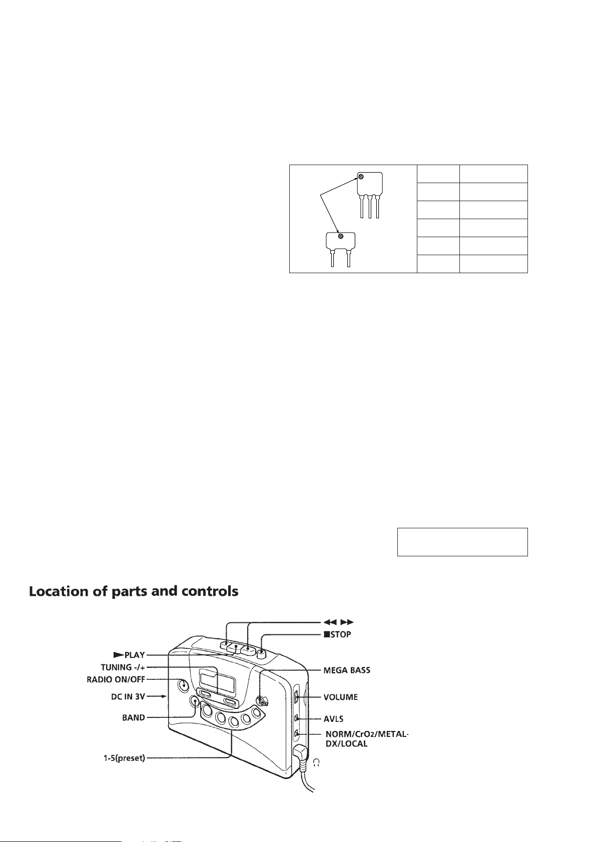
TABLE OF CONTENTS
SERVICING NOTES
Specifications ........................................................................... 1
1. GENERAL ...................................................................... 2
2. DISASSEMBLY
2-1. Cabinet (Front) ASSY ................................................ 3
2-2. Main Board ................................................................. 4
2-3. Cassette Holder........................................................... 4
2-4. Mechanism Deck (MF-WMFX251-114).................... 5
2-5. Belt, Motor (Capstan/Reel) (M901),
Playback Head (HP901).............................................. 5
3. MECHANICAL ADJUSTMENTS ............................ 6
4. ELECTRICAL ADJUSTMENTS
Tape Section....................................................................... 6
Tuner Section ..................................................................... 7
5. DIAGRAMS
5-1. Explanation of IC Terminals ....................................... 9
5-2. Block Diagram.......................................................... 10
5-3. Printed Wiring Boards .............................................. 13
5-4. Schematic Diagram................................................... 17
6. EXPLODED VIEWS
6-1. Main Section-1 ......................................................... 22
6-2. Main Section-2 ......................................................... 23
6-3. Mechanism Deck Section ......................................... 24
HOW TO CHANGE THE CERAMIC FILTERS
This model is used two ceramic filters of CF2 and X2.
You must used same type of color marked ceramic filters in order
to meet same specifications.
Therefore, the ceramic filter must changed two pieces together
since it's supply two pieces in one package as a spare parts.
CF2
mark
X2
Flexible Circuit Board Repairing
• Keep the temperature of the soldering iron around 270°C during
repairing.
• Do not touch the soldering iron on the same conductor of the
circuit board (within 3 times).
• Be careful not to apply force on the conductor when soldering
or unsoldering.
Notes on chip component replacement
• Never reuse a disconnected chip component.
• Notice that the minus side of a tantalum capacitor may be damaged by heat.
Mark Center frequency
red 10.70MHz
blue 10.67MHz
orange 10.73MHz
black 10.64MHz
white 10.76MHz
7. ELECTRICAL PARTS LIST .................................... 25
SECTION 1
GENERAL
This section is extracted from
instruction manual.
– 2 –
SECTION 2
DISASSEMBLY
r
The equipment can be removed using the following procedure.
Set
Cabinet (Front) ASSY
Note : Follow the disassembly procedure in the numerical order given.
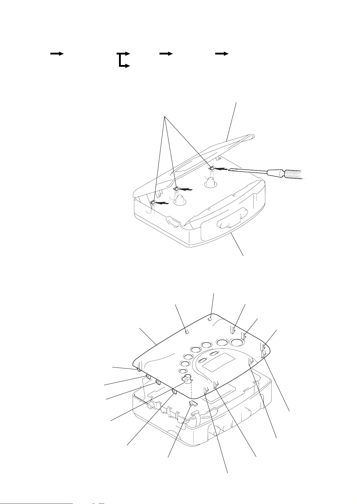
2-1. CABINET (FRONT) ASSY
1
Insert the precision screwdriver
(1.4 mm flat-blade) in to the slit
at claw A and release the claw.
Note: To avoid the damage to the
cabinet, wrap a point of
2
screwdriver with cloth.
Remove the cabinet (front) ASSY.
(Release all claw B to N in
alphabetical order.)
Main board
Cassette holder
Mechanism deck
(MF-WMFX251-114)
A
Belt, Motor (Capstan/Reel) (M901),
Playback head (HP901)
Cassette holder
N
M
L
Joint (MB)
Cabinet (front) ASSY
B
Cabinet (front) ASSY
C
D
E
F
G
Note: On installation cabinet (front) ASSY
adjust the S306 and joint (MB).
K
S306
H
I
J
– 3 –
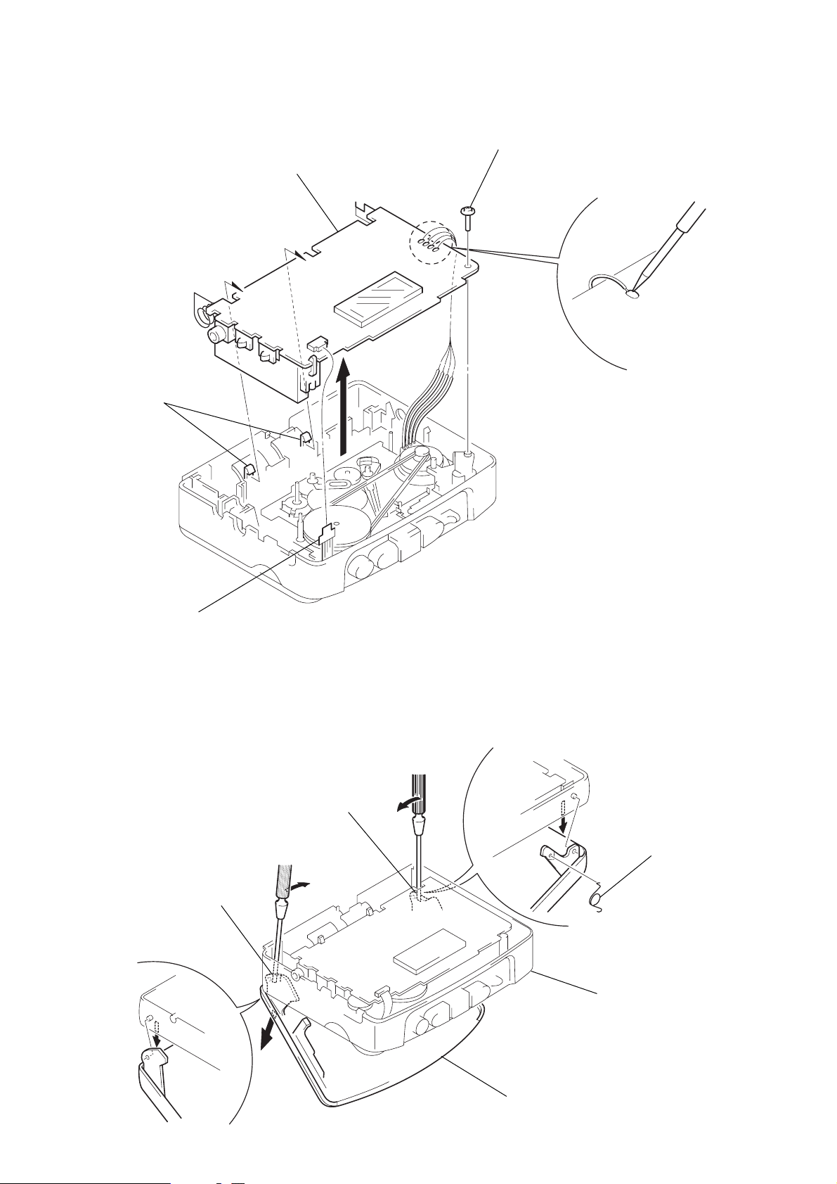
2-2. MAIN BOARD
4
Two claws
5
Main board
3
Screw (M1.4)
2
Remove the
four solders.
1
Flexible board
(CN301)
2-3. CASSETTE HOLDER
2
Insert a precision screwdriver
(1.4 mm flat-blade) vertically
in to portion A to release the
hinge plate.
3
Portion B to release the
hinge plate.
A
2
B
3
5
Torsion spring
Center cabinet
– 4 –
1
Open the cassette holder.
4
Cassette holder
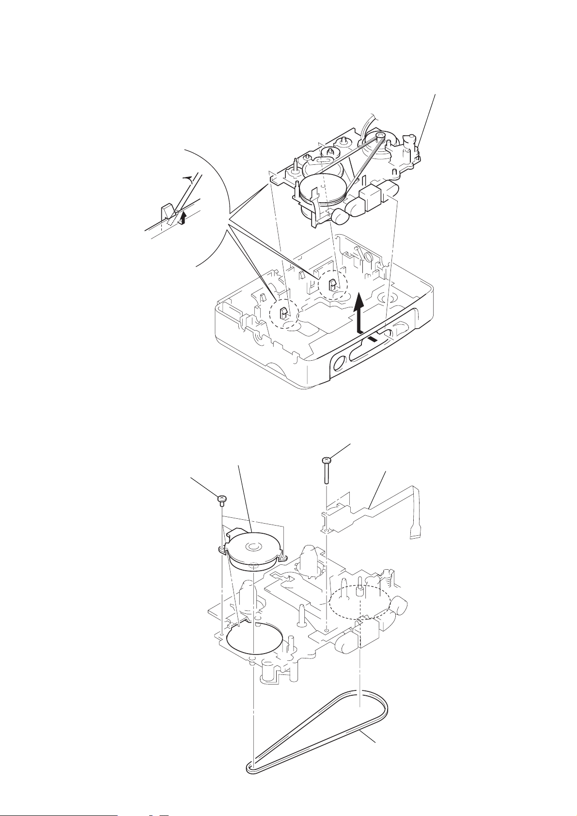
2-4. MECHANISM DECK (MF-WMFX251-114)
1
Insert the precision screwdriver
(1.4 mm flat-blade) in the slit
and relese two claws.
2
Remove the mechanism deck
(MF-WMFX251-114) in the
direction of the arrow
A
.
A
)
2-5. BELT, MOTOR (CAPSTAN/REEL) (M901), PLAYBACK HEAD (HP901)
2
Two screws
(M1.4
×
3
Motor (capstan/reel)
(M901)
1.6)
4
Screws (M1.4)
5
Playback head (HP901
– 5 –
1
Belt
SECTION 3
MECHANICAL ADJUSTMENTS
SECTION 4
ELECTRICAL ADJUSTMENTS
Precaution
1. Clean the following parts with a denatured-alcoholmoistened
swab:
playback head pinch roller
capstan rubber belt
2. Demagnetize the playback head with a head demagnetizer.
3. Do not use a magnetized screwdriver for the adjustments.
4. After the adjustments, apply suitable locking compound to the
parts adjusted.
5. The adjustments should be performed with the rated power supply voltage (2.5 V) unless otherwise noted.
Torque Measurement
Mode Torque Meter Meter Reading
FWD
FWD less than 2 g•cm
Back Tension (less than 0.03 oz•inch)
FF, REW CQ-201B
CQ-102C (0.28 – 0.58 oz•inch)
20 – 42 g•cm
more than 60 g•cm
(more than 0.83 oz•inch)
Precaution
• Supplied voltage: 2.5 V
• Switch and control position
TAPE switch: NORM
RADIO switch: DX
VOLUME CONTROL: maximum
AVLS switch: NORM
MEGA BASS switch: OFF
Test tape
Type Signal Used for
WS-48A 3 kHz, 0 dB Tape Speed Adjustment
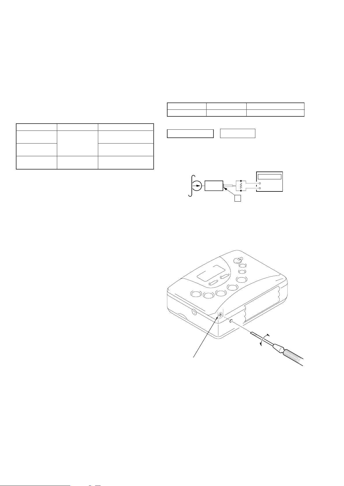
TAPE SECTION
0 dB=0.775 V
Tape Speed Adjustment
Procedure:
test tape
WS-48A
(3 kHz, 0dB)
set
frequency counter
16
Ω
2
jack (J301)
+
–
Playback WS-48A (tape center part) and adjust RV601 so that the
frequency counter reading becomes 3,000 Hz.
Standard value: 2,985 to 3,015 Hz
Adjustment Location:
RV601
– 6 –
 Loading...