

Sony WMGX-888 Service manual
WM-GX680/GX688
SERVICE MANUAL
Ver 1.2 2002. 01
Photo: WM-GX688
Manufactured under license from Dolby Laboratories
Licensing Corporation.
“DOLBY” and the double-D symbol a are trademarks
of Dolby Laboratories Licensing Corporation.
US Model
AEP Model
WM-GX680
E Model
Tourist Model
WM-GX688
Chinese Model
WM-GX680/GX688
Model Name Using Similar Mechanism WM-GX677
Tape Transport Mechanism Type MF-WMGX670-162
SPECIFICATIONS
Radio section
Frequency range
FM : 76.0 ~ 90.0 MHz (Tourist Model)
: 87.5 ~ 108 MHz (Other Models)
AM : 531 ~ 1710 kHz (Tourist, US Models)
: 531 ~ 1 602 kHz (Other Models)
Tape section
Frequency response
(Dolby NR off)
Playback: 40 - 15 000 Hz
Recording/playback: 100 - 8 000 Hz
Output
Headphones (iREMOTE) jack
Load impedance 8 - 300 Ω
Input
Microphone (MIC) jack
General
Power requirements
1.5 V
Rechargeable battery
One R6 (size AA) battery
Dimensions (w/h/d)
Approx. 108.4 × 77.7 × 23.0 mm
3
(4
⁄8 × 31⁄8 × 29⁄32 inches)
Mass
Approx. 148 g (5.3 oz)
Supplied accessories
Battery case (1)
Stereo headphones or earphones with
remote control (1)
Battery charger (1)
AC plug adaptor (1) (Saudi Arabian,
Tourist model)
Rechargeable battery (NC-6WM, 1.2 V,
600 mAh, Ni-Cd) (1)
Rechargeable battery carrying case (1)
Carrying pouch (1)
Stereo microphone (1)
Design and specifications are subject to
change without notice.
9-873-034-12
2002A1600-1
© 2002.1
RADIO CASSETTE-CORDER
Sony Corporation
Personal Audio Company
Published by Sony Engineering Corporation

TABLE OF CONTENTS
1. SERVICE NOTE ······························································· 3
2. GENERAL ··········································································5
3. DISASSEMBLY
3-1. Case assy·········································································6
3-2. Belt··················································································7
3-3. Lid block assy, cassette ··················································· 7
3-4. Ornament, reel ································································ 8
3-5. Main Board ·····································································8
3-6. Motor (M601) ·································································9
3-7. Holder (F) Assy······························································· 9
3-8. Lever (N)/(R) Assy, pinch ············································· 10
3-9. Head, magnetic (HP901)··············································· 10
4. MECHANICAL ADJUSTMENT ································ 11
5. ELECTRICAL ADJUSTMENT ·································· 11
6. DIAGRAMS
6-1. Block Diagram ······························································ 13
6-2. Schematic Diagram (1/3) ·············································· 16
6-3. Schematic Diagram (2/3) ·············································· 19
6-4. Schematic Diagram (3/3) ·············································· 21
6-5. IC Block Diagrams ·······················································23
6-6. Printed Wiring Board (SIDE A)···································· 25
6-7. Printed Wiring Board (SIDE B) ···································· 27
6-8. IC Pin Function Discription ·········································· 29
7. EXPLODED VIEWS
7-1. Cabinet Block, Main Board ··········································31
7-2. Mechanism Deck Block················································ 32
8. ELECTRICAL PARTS LIST ······································· 33
SAFETY-RELATED COMPONENT WARNING!!
COMPONENTS IDENTIFIED BY MARK ! OR DOTTED LINE WITH
MARK ! ON THE SCHEMATIC DIAGRAMS AND IN THE PARTS
LIST ARE CRITICAL TO SAFE OPERATION. REPLACE THESE
COMPONENTS WITH SONY PARTS WHOSE PART NUMBERS
APPEAR AS SHOWN IN THIS MANUAL OR IN SUPPLEMENTS
PUBLISHED BY SONY.
Notes on chip component replacement
• Never reuse a disconnected chip component.
• Notice that the minus side of a tantalum capacitor may be
damaged by heat.
Flexible Circuit Board Repairing
• Keep the temperature of soldering iron around 270˚C
during repairing.
• Do not touch the soldering iron on the same conductor of the
circuit board (within 3 times).
• Be careful not to apply force on the conductor when soldering
or unsoldering.
— 2 —
SECTION 1
SERVICE NOTE
[Service Mode]
The service mode enables to operate the mechanism of WM-GX680/
688 while the MAIN board is opened.
Rotation of the idler gear (A) (S side) is detected using the photoreflector (PH1) in the WM-GX680/688. PH1 is located on the MAIN
board, therefore the rotation of the idler gear (A) (S side) cannot be
detected by PH1 when the MAIN board is removed. As a result, the
motor cannot be controlled and cannot run correctly.
To repair the machine after the MAIN board is removed while the
main power is turned on, follow the procedures as described below.
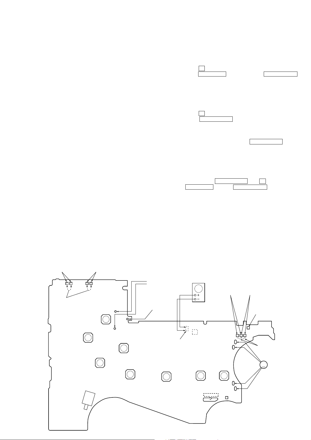
1. Setting
1) Remove the cabinets referring to section “3. DISASSEMBL Y”.
Open the MAIN board.
2) Connect the motor (M601) and the plunger solenoid (PM901)
to the MAIN board using the jumper wires. When the extension
jig (1-769-143-11) (10 wires as a set) is used, they can be
connected easily.
3) Short the TAPE DETECT switch (S901-2), R TUME switch
(S901-1), F TUME switch (S902-1) and ATS switch (S902-2).
4) Connect an AF oscillator to resistor (R43).
5) Connect DC 1.3 V from e xternal regulated power supply to ‘
and ’ terminals of the battery.
2. PRE-SET status
The PLA Y, FF and REW modes can be entered only from the PRESET status.
1) Check that the slider (NR) is in the center position (S1), and
the FWD/REV switch is also in the center position. When
these switches are not in the center position, set them to the
PRE-SET status as follows.
2) Move the FWD/REV switch (S1) to the same position as the
slider (NR) is set.
3) The slider (NR) can be moved when the main power of the
regulated power supply is turned OFF once then back ON.
Move the FWD/REV switch (S1) to the center position in
synchronism with the timing when the slider (NR) is moved.
3. FF, REW modes
1) Check that the PRE-SET status is set.
2) Connect square wave or sine wave to resistor (R43). (See
illustration below.)
3) Press the p switch (S3) to enter the STOP mode.
4) Press the FF PRESET+ switch (S4) and the REW PRESET–
switch (S5).
4. PLAY mode
1) Check that the PRE-SET status is set.
2) Connect square wave or sine wave to resistor (R43). (See
illustration below.)
3) Press the p switch (S3) to enter the STOP mode.
4) When the 9(REPEAT switch (S9) of the MAIN board is
pressed, the slider (NR) moves once to the F side then moves
to the R side. When the FWD/REV switch (S1) is pressed in
the synchronism with the above timing, the machine can enter
the PLAY (R side) mode. Press the 9(REPEAT switch
(S9) again, and move the FWD/REV switch (S1) in the
synchronism with the motion of slider (NR). It enables the
machine to enter into the PLAY (F side) mode.
Note 1: When you fail to enter the PLAY mode, re-start from step
1) PRE-SET status.
Note 2: Regarding the 9(REPEAT (S9), p (S3),
FF PRESET+ (S4), and REW PRESET– (S5) switches,
use these switches of the remote control unit as much as
possible.
Note 3: If a headphones are used, the beep sound shows the timing
of the FWD/REV switch (S1).
R TUME
SWITCH
(S901-1)
Short
TAPE DETECT
SWITCH
(S901-2)
FF PRESET +
(S4)
REW PRESET –
(S5)
p
(S3)
œ
REPEAT
(S9)
ENTER
(S10)
– MAIN BOARD (SIDE B) —
Plunger (PM901)
R43
Square wave
10 Hz, -3.5 dB
(SIDE A)
Battery terminal
BAND
(S8)
’
(SIDE A)
AF OSC
(sine wave)
Q15
MENU
(S6)
FWD
←
ATS
SWITCH
(S902-2)
SET
(S7)
(S1)
STOP→REV
F TUME
SWITCH
(S902-1)
Battery terminal
Short
M
‘
M601
REC
(S11)
— 3 —
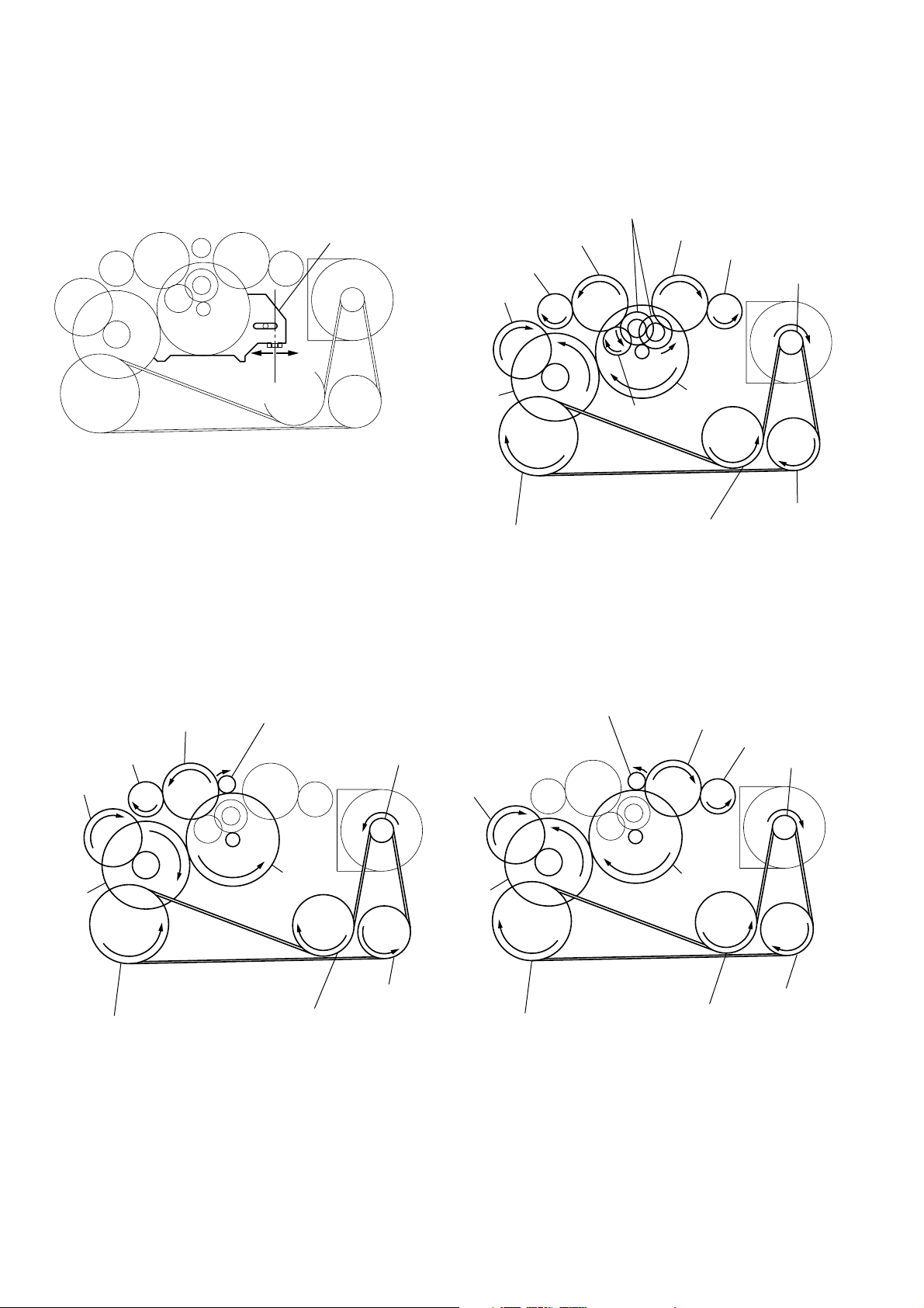
[ Slider (NR) ] [ Tape drive mechanism ]
y
Tape drive mechanism in PLAY mode
Gear (NR)
(FWD : Left side
REV : Right side)
Idler Gear
(A)(T side)
Gear
Idler Gear(B)
F side
Center
Slider (NR)
(REEL)(T side)
Cam Gear
R side
Gear (Y)
Insert Flywheel (N)
Idler Gear (A)(S side)
Gear (REEL)(S side)
Motor Pulley
Clutch Assy(F)
Pulley (Reverse)
Insert Flywheel (R)
Tape drive mechanism in FF mode
Idler Gear
(A)(T side)
Gear
(REEL)(T side)
Cam Gear
Gear (Y)
Insert Flywheel (N)
Gear (FR)
(FF : Left side)
Insert Flywheel (R)
Clutch Assy(F)
Pulley (Reverse)
Motor Pulle
Tape drive mechanism in REW mode
Gear (FR)
(REW : Right side)
Cam Gear
Gear (Y)
Insert Flywheel (N)
Idler Gear
(A)(S side)
Clutch Assy(F)
Insert Flywheel (R)
Gear
(REEL)(S side)
Motor Pulley
Pulley (Reverse)
— 4 —
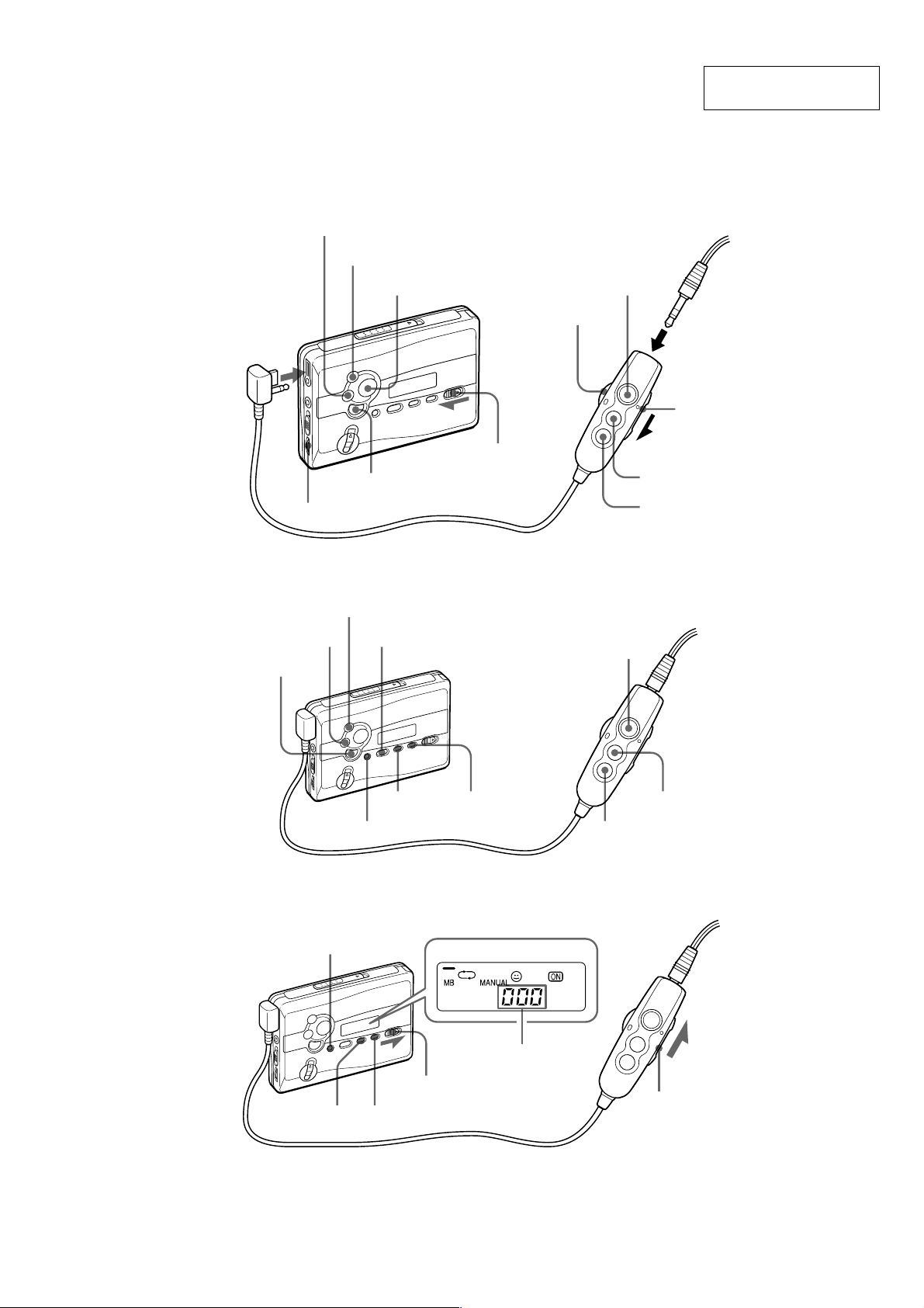
• LOCATION OF CONTROLS
REW (AMS)
FF (AMS)
SECTION 2
GENERAL
This section is extracted
from instruction manual.
Y•REPEAT
iREMOTE
x
VOL
TUNE/PRESET +
TUNE/PRESET – RADIO ON/BAND
RADIO OFF
Y•x
VOL
Plug in firmly.
HOLD
HOLD
FF
REW
RADIO ON/
BAND•OFF
ENTER
ENTER/COUNTER RESET
MENU
SET
SETMENU
PB TUNE FM PB
SOUND MODE MODE AVLS MODEaNR
Tape counter
HOLD
PRESET +
PRESET –
HOLD
— 5 —
DISASSEMBLY
Note : Disassemble the unit in the order as shown below.
SECTION 3
Set Case assy
Belt
Lid block assy, cassette Main board
Motor
(M601)
Holder (F)
assy
Lever (N)/(R) assy,
pinch
Note : Follow the disassembly procedure in the numerical order given.
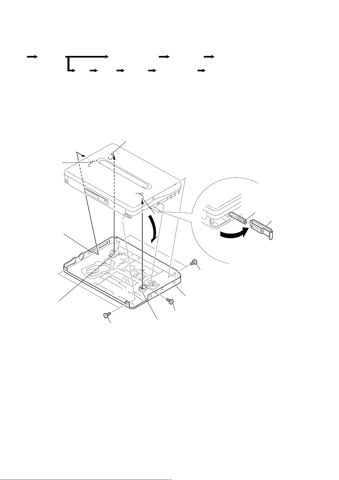
3-1. CASE ASSY
S11
S501
knob (ISS)
Note: When assembling the
case assy, align the
knob (ISS) with the
position of S501.
S2
Ornament, reel
Head, magnetic
(HP901)
Claw
1 Lid, Battery
knob (REC)
Note: When assembling the
case assy, align the
knob (REC) with the
position of S11.
4 Two screws
(M1.4 × 2.5)
2 Two screws
(M1.4 × 2.0)
5 Remove the case assy
in the direction of the arrow.
3 Screw (M1.4 × 2.0)
knob (HOLD-B)
Note: When assembling the
case assy, align the
knob (HOLD-B) with the
position of S2.
— 6 —
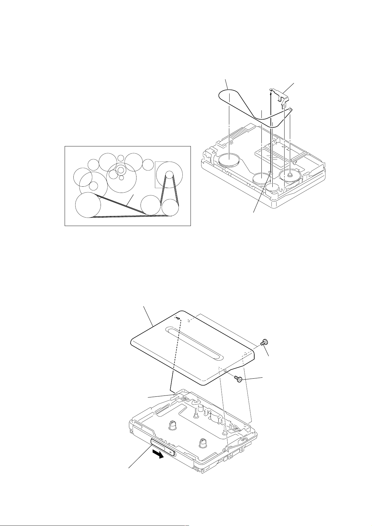
3-2. BELT
d
Belt threading
Belt
3 Belt
2 Terminal boar
(Battery ’)
1 Remove solder from
the battery terminal board.
3-3. LID BLOCK ASSY, CASSETTE
5 Lid block assy, cassette
4 Shaft
2 Two screws (M1.4 × 2.0)
1 Screw (M1.4 × 2.0)
3 Open the cassette lid
— 7 —
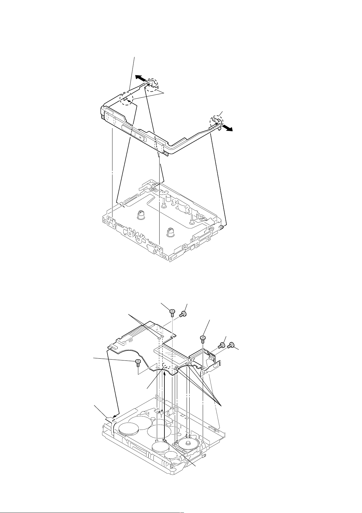
3-4. ORNAMENT, REEL
g
1 Ornament, reel
Remove the assembly while removin
Note:
the three claws and boss carefully.
Claw
Claw
3-5. MAIN BOARD
7
Screw (M1.4)
Toothed lock
1
Ats flexible board
8
Remove soldering
(two points)
from plunger solenoid.
6
Screw (B1.7 × 3)
tapping
S1
2
Screw (M1.4)
5
Screw (B1.7 × 3)
tapping
3
Screw (1.4 × 1.6)
9
Remove soldering
(four points) from
motor.
4
Screw (M1.4)
— 8 —
SLIDER
Note:
When assembling the MAIN board,
align the slider with the position of S1.
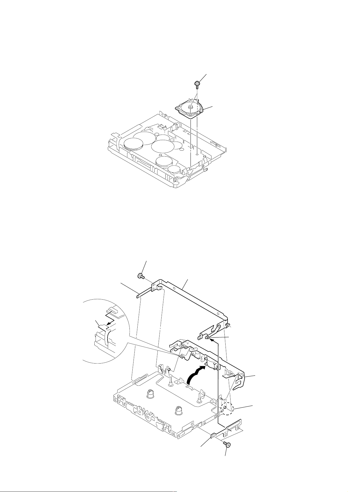
3-6. MOTOR (M601)
1 Two screws (M1.4)
Toothed lock
2 Motor (M601)
3-7. HOLDER (F) ASSY
5 Lever (S), lock
8 Flexible board
4 Screw (M1.4)
7 Bracket (cassette) assy
2 Shaft
9 Remove the holder (F)
assy in the direction
of the arrow.
6 Shaft
3 Lever (B), lock
— 9 —
1 Two screws (M1.4 × 1.6)
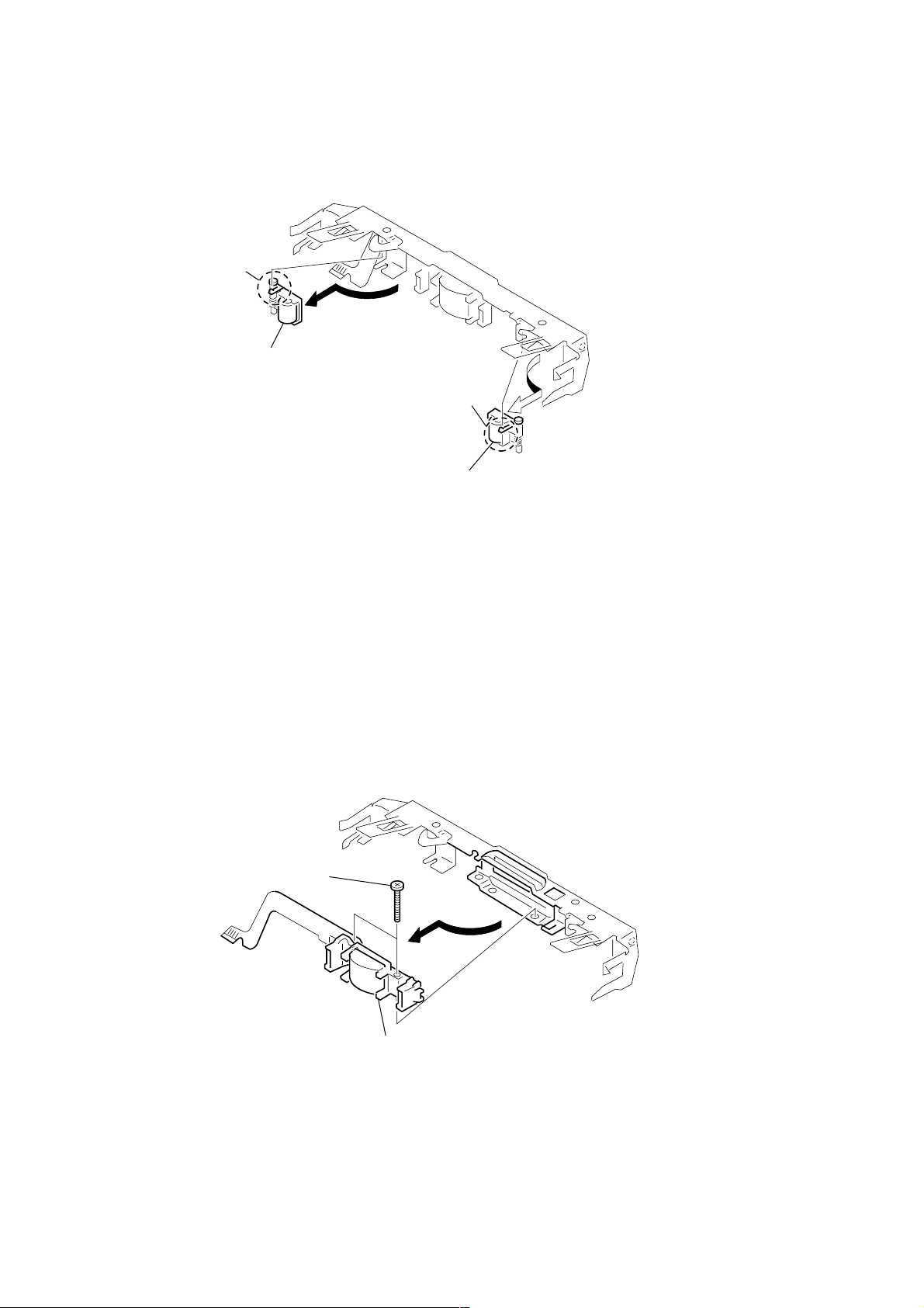
3-8. LEVER (N) / (R) ASSY, PINCH
Claw
2 Remove the lever (N) assy, pinch
in the direction of the arrow.
Note: Be careful of the claw
Claw
1 Remove the lever (R) assy, pinch
in the direction of the arrow.
Note: Be careful of the claw
3-9. HEAD, MAGNETIC (HP901)
1 Two screws
(M1.4 × 7.2)
2 Remove the head, magnetic (HP901)
in the direction of the arrow.
— 10 —
 Loading...