

WM-GX780/GX788
SERVICE MANUAL
Ver 1.1 2003. 10
Photo: WM-GX788
US Model
AEP Model
WM-GX788
E Model
Chinese Model
WM-GX780/GX788
Tourist Model
WM-GX788
Model Name Using Similar Mechanism NEW
Tape Transport Mechanism T ype MF-WMGX788-162
SPECIFICATIONS
Radio section
Frequency range
FM:
87.5 - 108 MHz
530 - 1 710 kHz (North, Central,
AM:
and South America)
531 - 1 602 kHz (other
countries/regions)
Tape section
Frequency response
Playback: 40 - 15 000 Hz
Recording/playback: 100 - 8 000 Hz
Output
Headphones (i) jack
Load impedance 8 - 300 Ω
Input
Microphone (MIC) jack
General
Power requirements
1.5 V
Rechargeable battery
One R6 (size AA) battery
Dimensions (w/h/d)
Approx. 77.1 × 108.0 × 22.5 mm
1
(3
⁄8 × 43⁄8 × 29⁄32 inches) excl. projecting
parts and controls
Mass
Approx. 152 g (5.4 oz) (main unit only)
Supplied accessories
AC power adaptor (1)
Battery case (1)
Stereo headphones or earphones with
remote control (1)
Charging stand (1)
AC plug adaptor (1) (Saudi Arabian
model only)
Rechargeable battery (NH-14WM(A),
1.2 V, 1 350 mAh (min), Ni-MH) (1)
Rechargeable battery carrying case (1)
Carrying pouch (1)
Stereo microphone (1)
Design and specifications are subject to
change without notice.
9-877-201-02
2003J16-1
© 2003.10
RADIO CASSETTE-CORDER
Sony Corporation
Personal Audio Company
Published by Sony Engineering Corporation

WM-GX780/GX788
TABLE OF CONTENTS
1. SERVICE NOTE······························································· 3
2. GENERAL ··········································································5
3. DISASSEMBLY
3-1. Case Block Assy ····························································· 6
3-2. Button Rec, Button Assy················································· 7
3-3. Cassette Lid Assy···························································· 7
3-4. Ornament Block Assy Reel, Flexible Retainer ··············· 8
3-5. MAIN Board, Belt (F0) ·················································· 8
3-6. Motor (M901) ·································································9
3-7. Bracket (cassette) Assy, Holder (FA) Assy ····················· 9
3-8. Pinch Lever (RA) Assy, Pinch Lever (NA) Assy ·········· 10
3-9. Magnetic Head (HP901) ··············································· 10
4. MECHANICAL ADJUSTMENT ································ 11
5. ELECTRICAL ADJUSTMENT ··································11
6. DIAGRAMS······································································12
6-1. Block Diagram ······························································ 13
6-2. Printed Wiring Board (Side A) ······································ 14
6-3. Printed Wiring Board (Side B)······································ 15
6-4. Schematic Diagram (1/2) ·············································· 16
6-5. Schematic Diagram (2/2) ·············································· 17
6-6. IC Block Diagrams ······················································· 18
6-7. IC Pin Function Discription ·········································· 19
7. EXPLODED VIEWS
7-1. Case Section·································································· 21
7-2. Main Section ································································· 22
7-3. Mechanism Deck Section (MF-WMGX788-162) ········ 23
8. ELECTRICAL PARTS LIST ······································· 24
SAFETY-RELATED COMPONENT WARNING!!
COMPONENTS IDENTIFIED BY MARK 0 OR DOTTED LINE WITH
MARK 0 ON THE SCHEMATIC DIAGRAMS AND IN THE PARTS
LIST ARE CRITICAL TO SAFE OPERATION. REPLACE THESE
COMPONENTS WITH SONY PARTS WHOSE PART NUMBERS
APPEAR AS SHOWN IN THIS MANUAL OR IN SUPPLEMENTS
PUBLISHED BY SONY .
Notes on chip component replacement
•Never reuse a disconnected chip component.
• Notice that the minus side of a tantalum capacitor may be
damaged by heat.
Flexible Circuit Board Repairing
•Keep the temperature of soldering iron around 270˚C
during repairing.
• Do not touch the soldering iron on the same conductor of the
circuit board (within 3 times).
• Be careful not to apply force on the conductor when soldering
or unsoldering.
UNLEADED SOLDER
Boards requiring use of unleaded solder are printed with the leadfree mark (LF) indicating the solder contains no lead.
(Caution: Some printed circuit boards may not come printed with
the lead free mark due to their particular size)
: LEAD FREE MARK
Unleaded solder has the following characteristics.
• Unleaded solder melts at a temperature about 40 ˚C higher than
ordinary solder.
Ordinary soldering irons can be used but the iron tip has to be
applied to the solder joint for a slightly longer time.
Soldering irons using a temperature regulator should be set to
about 350 ˚C .
Caution: The printed pattern (copper foil) may peel away if the
heated tip is applied for too long, so be careful!
• Strong viscosity
Unleaded solder is more viscous (sticky , less prone to flow) than
ordinary solder so use caution not to let solder bridges occur
such as on IC pins, etc.
• Usable with ordinary solder
It is best to use only unleaded solder but unleaded solder may
also be added to ordinary solder.
2
SECTION 1
SERVICE NOTE
[Service Mode]
The service mode enables to operate the mechanism of WM-GX780/
GX788 while the MAIN board is opened.
Rotation of the idler gear (A) (S side) is detected using the photoreflector (PH701) in the WM-GX780/GX788. PH701 is located on
the MAIN board, therefore the rotation of the idler gear (A) (S side)
cannot be detected by PH701 when the MAIN board is removed.
As a result, the motor cannot be controlled and cannot run correctly .
To repair the machine after the MAIN board is removed while the
main power is turned on, follow the procedures as described below.
1. Setting
1) Remove the cabinets referring to section “3. DISASSEMBL Y”.
Open the MAIN board.
2) Connect the motor (M601) and the plunger solenoid (PM901)
to the MAIN board using the jumper wires. When the extension
jig (1-769-143-11) (10 wires as a set) is used, they can be
connected easily.
3) Short the TAPE DETECT switch (S303), REV TUME switch
(S503), FWD TUME switch (S502) and ATS switch (S302).
4) Connect an AF oscillator to resistor (R712).
5) Connect DC 1.3 V from external re gulated power supply to ‘
and ’ terminals of the battery.
2. PRE-SET status
The PLA Y, FF and REW modes can be entered only from the PRESET status.
1) Check that the slider (NR) is in the center position (S801), and
the FWD/REV switch is also in the center position. When
these switches are not in the center position, set them to the
PRE-SET status as follows.
2) Move the FWD/REV switch (S801) to the same position as the
slider (NR) is set.
3) The slider (NR) can be moved when the main power of the
regulated power supply is turned OFF once then back ON.
Move the FWD/REV switch (S801) to the center position in
synchronism with the timing when the slider (NR) is moved.
WM-GX780/GX788
3. FF, REW modes
1) Check that the PRE-SET status is set.
2) Connect square wave or sine wave to resistor (R712). (See
illustration below.)
3) Press the x switch (S703) to enter the STOP mode.
4) Press the FF PRESET+ switch (S708) and the REW PRESET–
switch (S707).
4. PLAY mode
1) Check that the PRE-SET status is set.
2) Connect square wave or sine wave to resistor (R712). (See
illustration below.)
3) Press the x switch (S703) to enter the STOP mode.
4) When the nNREPEAT switch (S709) of the MAIN board
is pressed, the slider (NR) moves once to the F side then moves
to the R side. When the FWD/REV switch (S801) is pressed
in the synchronism with the above timing, the machine can
enter the PLAY (R side) mode. Press the nNREPEAT
switch (S709) again, and move the FWD/REV switch (S801)
in the synchronism with the motion of slider (NR). It enables
the machine to enter into the PLAY (F side) mode.
Note 1: When you fail to enter the PLAY mode, re-start from step
1) PRE-SET status.
Note 2: Regarding the nNREPEAT (S709), x (S703),
FF PRESET+ (S708), and REW PRESET– (S707)
switches, use these switches of the remote control unit as
much as possible.
Note 3: If a headphones are used, the beep sound shows the timing
of the FWD/REV switch (S801).
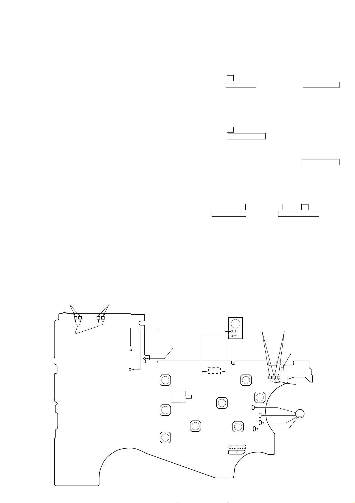
REV TUME
SWITCH
(S503)
Short
TAPE DETECT
SWITCH
(S303)
Battery terminal
ENTER
(S702)
SET
(S705)
MENU
(S706)
– MAIN BOARD (SIDE B) —
Plunger (PM901)
#
REC
(S710)
RADIO ON/
BAND
(S704)
R710
(Side A)
Y
REPEAT
(S709)
REW/PRESET–
(S801)
FWD
←
STOP→REV
(S707)
OSC
Sine wave
10 Hz, -3.5 dB
FF/PRESET+
(S708)
ATS
SWITCH
(S302)
FWD TUME
SWITCH
(S502)
Battery terminal
x
RADIO OFF
(S703)
Short
M
3
M601
3
WM-GX780/GX788
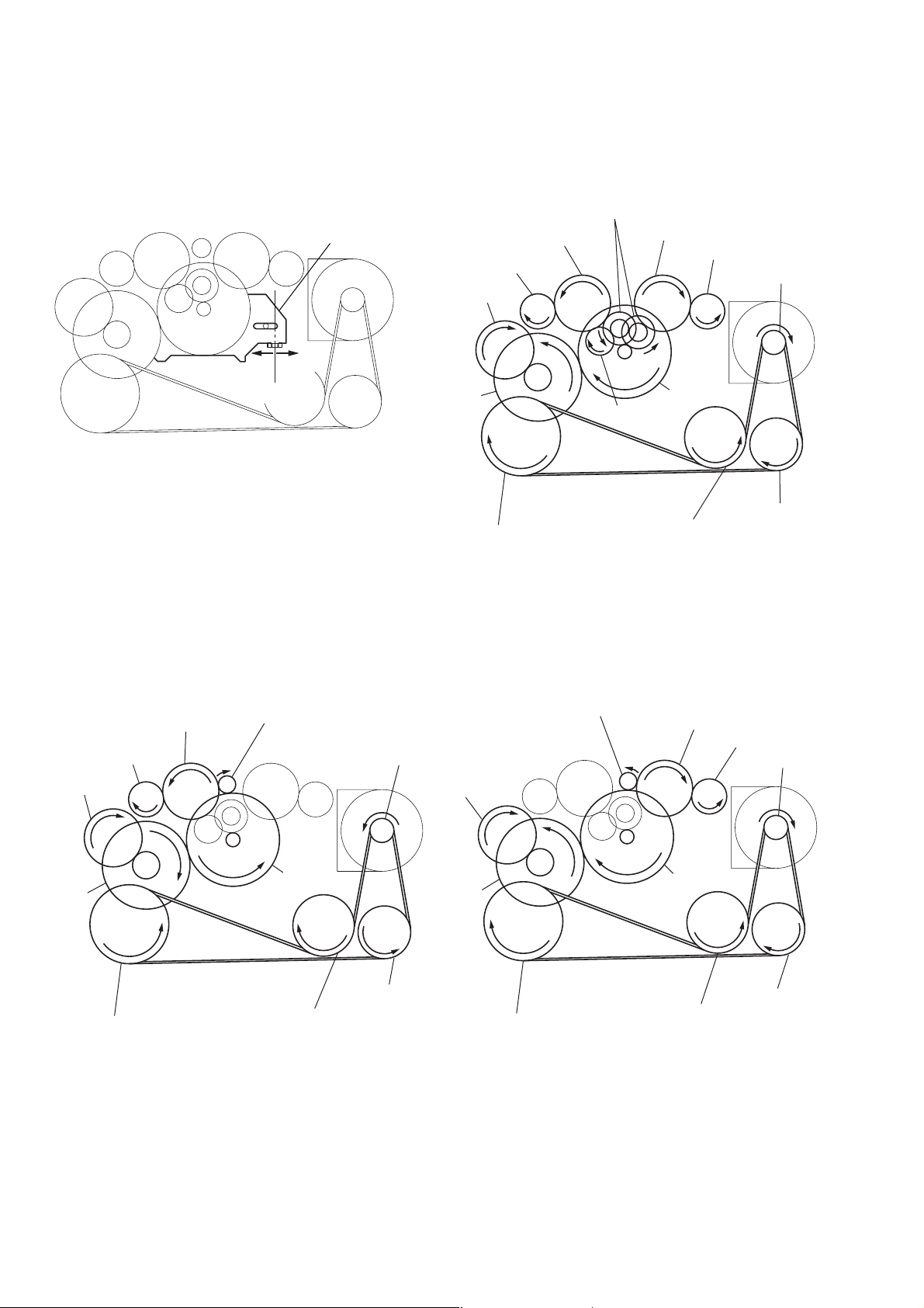
y
[ Slider (NR) ] [ Tape drive mechanism ]
Tape drive mechanism in PLAY mode
Gear (NR)
(FWD : Left side
REV : Right side)
Idler Gear
(A)(T side)
Gear
Idler Gear(B)
F side
Center
Slider (NR)
(REEL)(T side)
Cam Gear
R side
Gear (Y)
Idler Gear (A)(S side)
Gear (REEL)(S side)
Motor Pulley
Clutch Assy(F)
Tape drive mechanism in FF mode
Idler Gear
(A)(T side)
Gear
(REEL)(T side)
Cam Gear
Gear (Y)
Gear (FR)
(FF : Left side)
Clutch Assy(F)
Motor Pulle
Insert Flywheel (N)
Insert Flywheel (R)
Tape drive mechanism in REW mode
Gear (FR)
(REW : Right side)
Cam Gear
Gear (Y)
Idler Gear
(A)(S side)
Clutch Assy(F)
Pulley (Reverse)
Gear
(REEL)(S side)
Motor Pulley
Insert Flywheel (N)
4
Pulley (Reverse)
Insert Flywheel (R)
Pulley (Reverse)
Insert Flywheel (N)
Insert Flywheel (R)
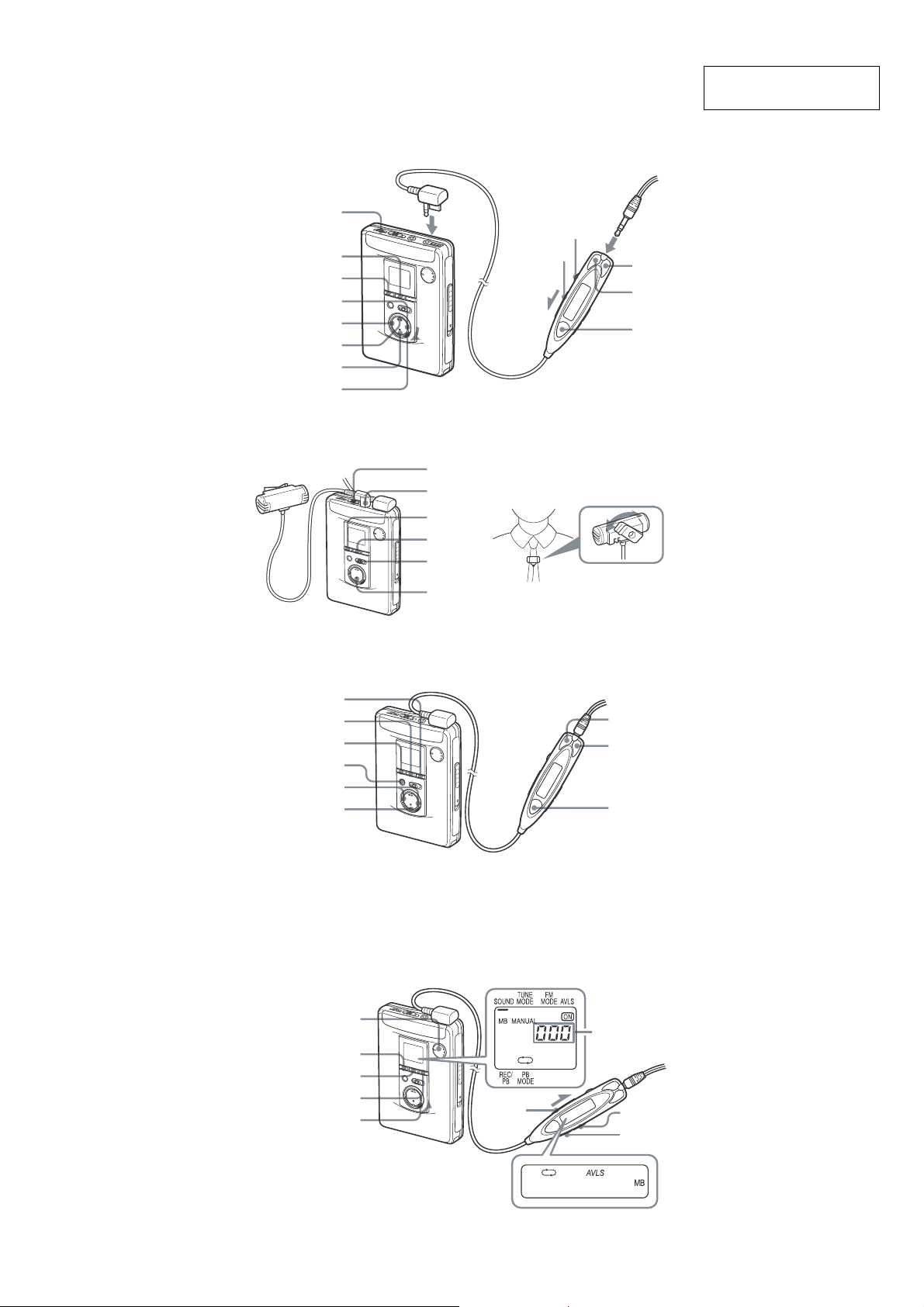
• LOCATION OF CONTROLS
FF/CUE
REW/REVIEW
Y•REPEAT**
VOL*
SET
MENU
HOLD
WM-GX780/GX788
SECTION 2
GENERAL
Plug in firmly.
i
x
ISS
MIC**
HOLD
VOL
REW –
FF +
Y•x
This section is extracted
from instruction manual.
ENTER
SET
MENU
RADIO ON/BAND
TUNE/PRESET –/+
RADIO OFF
MENU
SET
REC
x
FF +
REW –
RADIO ON/BAND
OFF
SPEED
CONTROL
MENU
SET
COUNTER RESET
ENTER/
HOLD
Tape counter
HOLD SOUND
MODE
5
WM-GX780/GX788
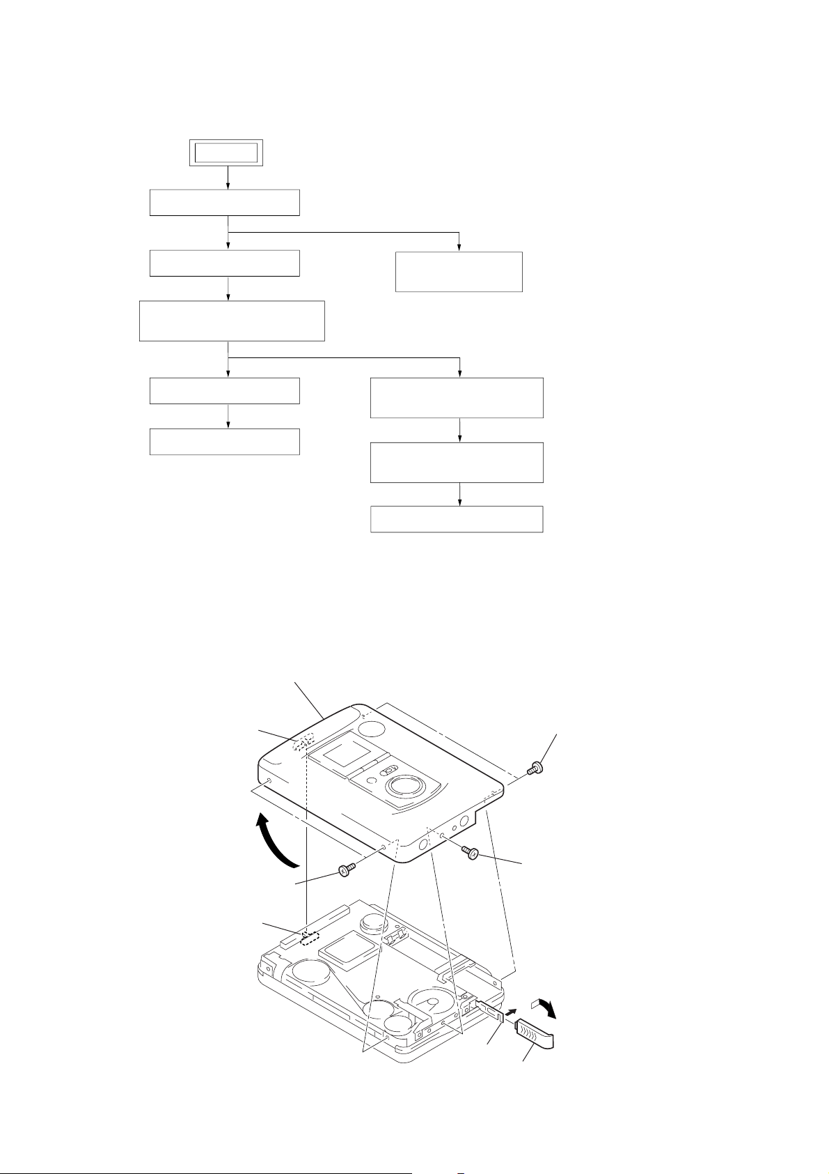
DISASSEMBLY
Note : Disassemble the unit in the order as shown below.
SET
CASE BLOCK ASSY
SECTION 3
CASSETTE LID ASSY
ORNAMENT BLOCK ASSY REEL,
FLEXIBLE RETAINER
MAIN BOARD, BELT (F0)
MOTOR (M901)
BRACKET (CASSETTE) ASSY,
HOLDER (FA) ASSY
PINCH LEVER (RA) ASSY,
PINCH LEVER (NA) ASSY
MAGNETIC HEAD (HP901)
Note : Follow the disassembly procedure in the numerical order given.
3-1. Case Block Assy
7
Remove the case block assy
in the direction of the arrow.
BUTTON REC,
BUTTON ASSY
knob (iss)
4
two screws
(M1.4)(EG)
S501
Note: On installation case block assy
adjust the S501 and knob (iss).
2
claw
5
3
battery lid
6
two screws
(M1.4)(EG)
screw
(M1.4)(EG)
1
Open the battery lid.
6
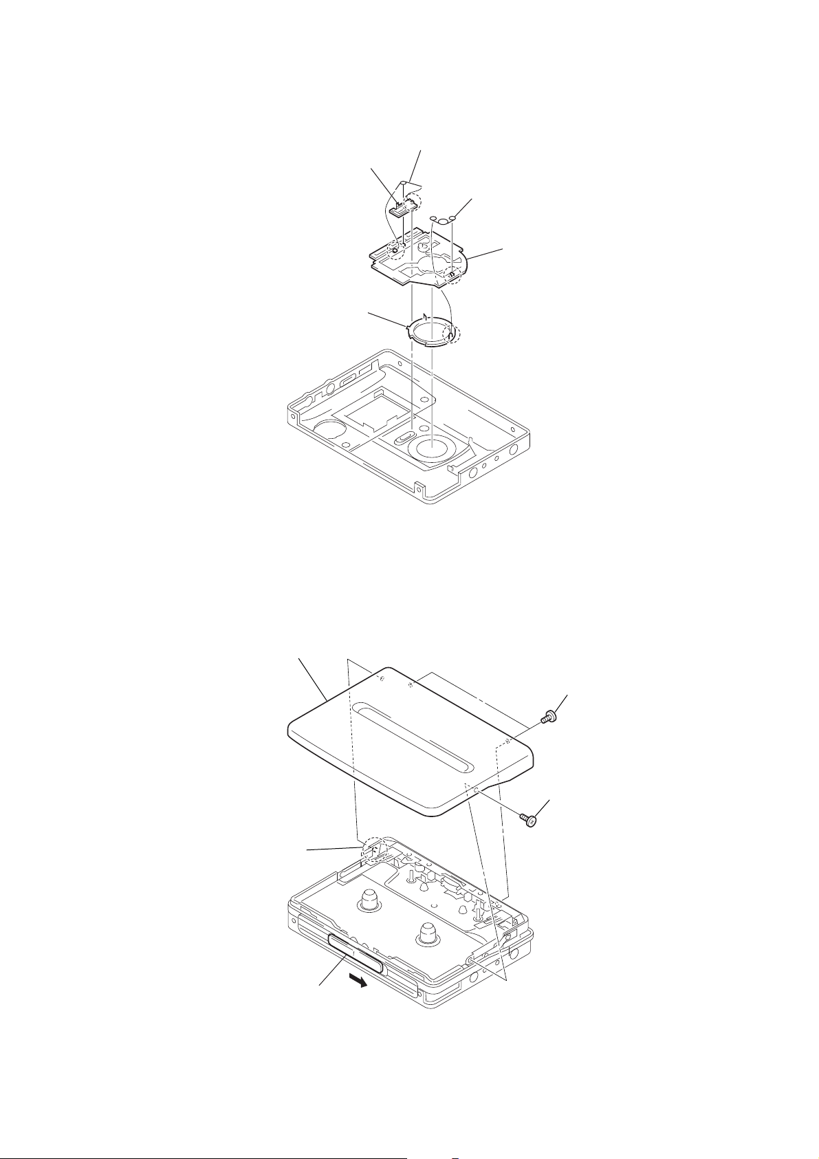
3-2. Button Rec, Button Assy
)
)
2
5
knob (hold)
button rec
1
rec spring
3
torion spring (hold
4
button assy
WM-GX780/GX788
3-3. Cassette Lid Assy
5
cassette lid assy
3
Slide the knob (open)
in the direction of the arrow.
4
shaft
2
two screws
(M1.4)(EG)
1
screw (M1.4)(EG
7
WM-GX780/GX788
f
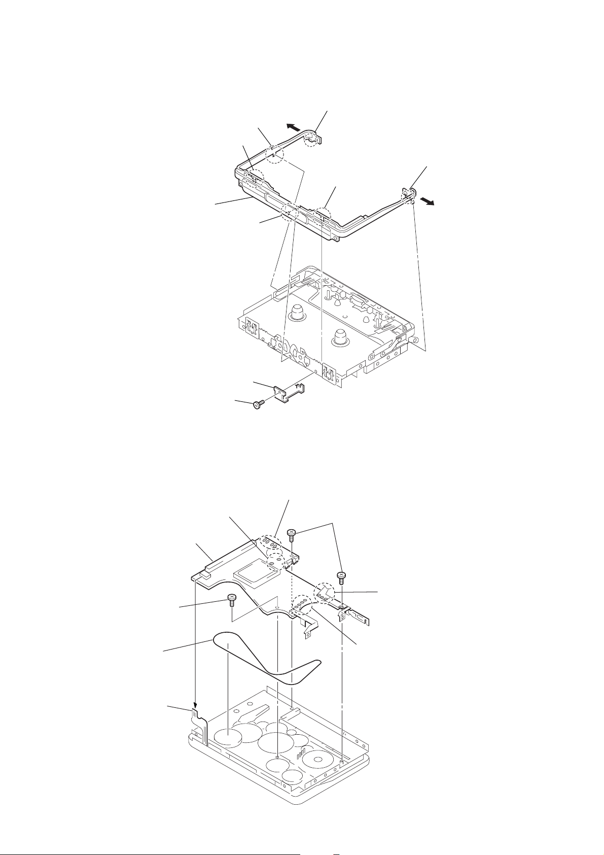
3-4. Ornament Block Assy Reel, Flexible Retainer
2
claw
3
claw
5
ornament block assy reel
4
boss
1
claw
3
claw
1
claw
3-5. MAIN Board, Belt (F0)
8
6
screw (M1.4)
9
belt (F0)
7
flexible retainer
6
screw (M1.4)
3
Remove two solders
of plunger solenoid.
MAIN board
4
Remove four solders
of leaf switch.
5
two screws
2
Remove three solders o
ATS flexible board.
1
Remove four solders of motor.
7
flexible board (head)
8
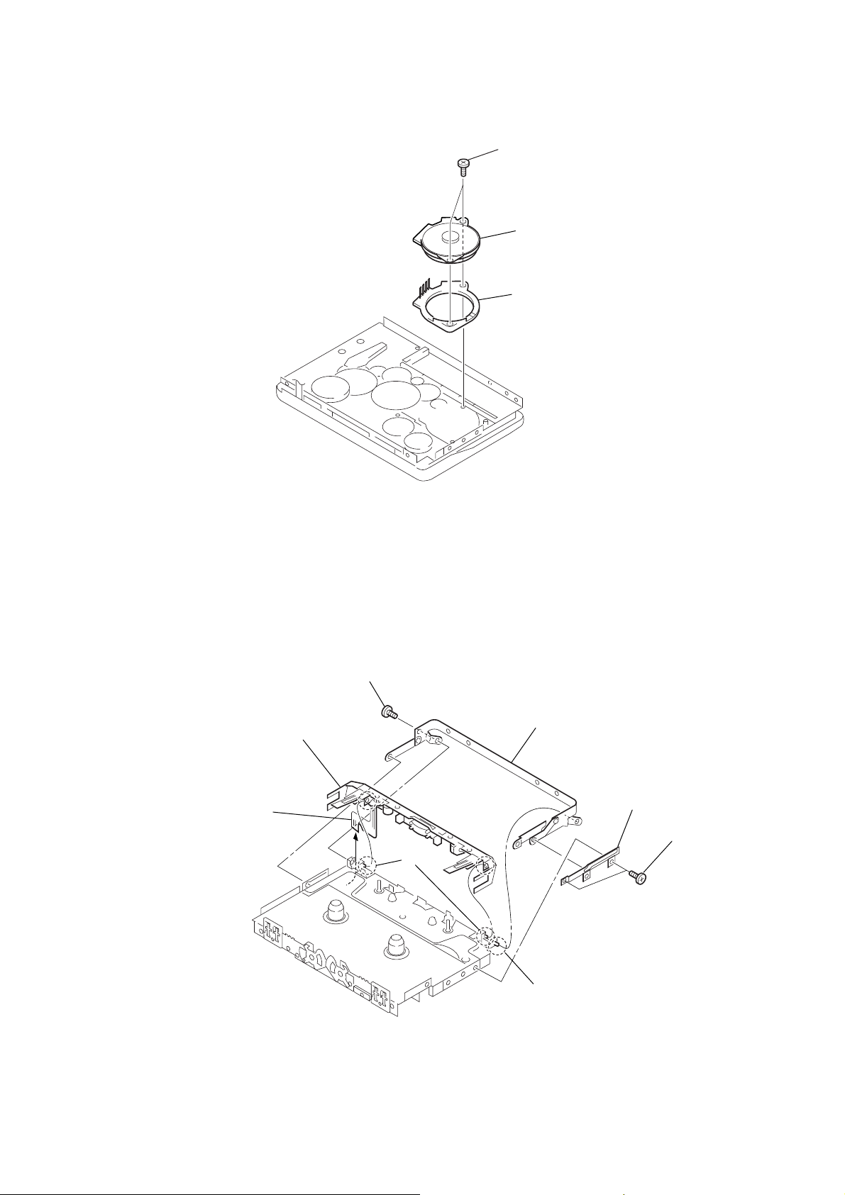
3-6. Motor (M901)
)
1
two screws (M1.4)
2
motor (M901)
3
motor retainer (F1
WM-GX780/GX788
3-7. Bracket (cassette) Assy, Holder (FA) Assy
3
screw (M1.4)
8
holder (FA) assy
6
flexible board (head)
7
shaft
5
bracket (cassette) assy
4
shaft
2
lock lever (B)
1
two screws
(M1.4
×
1.6)
9

WM-GX780/GX788
w
3-8. Pinch Lever (RA) Assy, Pinch Lever (NA) Assy
1
claw
2
Remove the pinch lever (RA) assy
in the dereciton of the arrow.
4
Remove the pinch lever (NA) assy
in the direction of the arrow.
3
cla
3-9. Magnetic Head (HP901)
1
claw
2
Remove the magnetic head (HP901)
in the direction of the arrow.
10

SECTION 4
)
r
MECHANICAL ADJUSTMENT
WM-GX780/GX788
SECTION 5
ELECTRICAL ADJUSTMENT
PRECAUTION
1. Clean the following parts with a denatured-alcohol-moistened
swab:
record/playback/erase head pinch roller
rubber belts capstan
2. Demagnetize the record/playback/erase head with a head
demagnetizer. (Do not bring a head demagnetizer close to the
erase head.)
3. The adjustments should be performed with the r ated power
supply voltage unless otherwise noted.
• T orque Measurement
Mode
Torque Meter
Meter Reading
1.47 to 2.45 mN•m
FWD
CQ-102C
(15 to 25 g•cm)
(0.21 to 0.34 oz•inch)
FWD
Back Tension
CQ-102C
Less than 0.20 mN•m
(Less than 2.0g•cm)
(Less than 0.028 oz•inch)
1.47 to 2.45 mN•m
REV
CQ-102RC
(15 to 25 g•cm)
(0.21 to 0.34 oz•inch)
REV
Back Tension
CQ-102RC
Less than 0.20 mN•m
(Less than 2.0g•cm)
(Less than 0.028 oz•inch)
More than 4.90 mN•m
FF, REW
CQ-201B
(More than 50 g•cm)
(More than 0.69 oz•inch)
Adjustment Parts Location :
PRECAUTION
1. Specified voltage : 1.3 V (DC)
2. Switch and control position
MENU switch
HOLD : OFF
VOL : MAX
ISS : 1
TAPE SECTION
Tape
WS-48A (4.8cm/s)
WS-24CC (2.4cm/s)
Signal
3 kHz, 0 dB
3 kHz, 0 dB
Tape Speed Adjustment
Procedure:
Test tape
WS-48A/24CC
(3kHz, 0dB)
Set
i REMOTE jack (J301)
1. Enter the FWD playback mode.
2. Confirm RV602 at center value. (mechanical center)
3. Adjust R V601 so that the value of the frequenc y counter reading
becomes 3,000 Hz.
Specification value:
Frequency counter
2,955 Hz – 3,045 Hz
4. Check that the frequency deviation at the be ginning and ending
of a tape is within 1.5 % (45 Hz).
5. Select switch to 2X (2.4 cm/s), then depress play button in and
adjust RV603 (2,955 Hz–3,045 Hz) at tape center.
Used for
Tape Speed Adjustment
Tape Speed Adjustment
Frequency counter
16 Ω
+
–
TUNER SECTION
0dB=1µV
[AM]
BAND switch : AM
AM RF signal
generator
30% amplitude modulation by 400Hz
signal.
Output level : as low as possible
Put the lead-wire
antenna close to
the set.
[FM]
BAND : FM
FM RF signal
generator
0.01µF
to ANT
22.5kHz frequency deviation by 400Hz signal.
Output level : as low as possible
level mete
16Ω
set
i REMOTE jack (J301)
+
–
•Repeat the procedures in each adjustment several times.
[MAIN BOARD] — SIDE A —
J501
J301
[MAIN BOARD] — SIDE B —
L5
L1
CT1
CT1 : AM frequency coverage
adjustment
L5 : AM frequency coverage
adjustment
L1 : FM frequency coverage
adjustment
RV603 RV601
WS-48A (4.8 cm/s
adjustment
WS-24CC (24 cm/s)
adjustment
AM FREQUENCY COVERAGE ADJUSTMENT
Adjust for a maximum reading on level meter.
620 kHz (US)
L5
621 kHz (Except US)
1400 kHz (US)
CT1
1395 kHz (Except US)
FM FREQUENCY COVERAGE ADJUSTMENT
Adjust for a maximum reading on level meter.
L1 76 MHz
Confirmation 108 MHz
1111

WM-GX780/GX788
SECTION 6
DIAGRAMS
Note for Printed Wiring Board and Schematic Diagrams
Note on Schematic Diagram:
• All capacitors are in µF unless otherwise noted. pF: µµF
50 WV or less are not indicated except for electrolytics
and tantalums.
• All resistors are in Ω and 1/
specified.
f
•
• C : panel designation.
• A : B+ Line.
• H : adjustment for repair.
•Power voltage is dc 1.5 V and fed with regulated dc power
•Voltages and waveforms are dc with respect to ground
: internal component.
supply from battery terminal.
under no-signal (detuned) conditions.
∗ : impossible to measure
Main board (1/2)
no mark : FM/AM, TAPE STOP
(): FM
[]: AM
<>: TAPE PB
Main board (2/2)
no mark : REC / PB
(): REC
[]: PB
•Voltages are taken with a VOM (Input impedance 10 MΩ).
Voltage var iations may be noted due to normal production tolerances.
•Waveforms are taken with a oscilloscope.
Voltage var iations may be noted due to normal production tolerances.
• Circled numbers refer to waveforms.
• Signal path.
E : PB
a : REC
F : FM
4
W or less unless otherwise
Note on Printed Wiring Board:
• Y : parts extracted from the conductor side.
• b : Pattern from the side which enables seeing.
Caution:
Pattern face side: Parts on the pattern face side seen from
(Side A) the pattern face are indicated.
Parts face side: Parts on the par ts face side seen from
(Side B) the parts face are indicated.
•Abbreviation
CH : Chinese model.
EA : Soudi Arabia model.
JE : Tourist model.
HK : Hong Kong model.
KR : Korea model.
• Wavef orm
1
T401 DD CON OUT
9MHz
IC701 ua XOUT 5µsec/div
2
0.5V/div
75kHz
100nsec/div
5V/div
1212

6-1. Block Diagram
FWD REC/PB HEAD
REV REC/PB HEAD
D1(1/2)
D1(2/2)
FWD
ERACE HEAD
REV
D3
CT1
AM FREQUENCY
L
R
L
R
L5,CT1
COVERAGE
L2D2
TV FREQUENCY
L1D4
FM FREQUENCY
L3
L5
L4
BIAS
Q509
FL1
HPF
FL2
BPF
L2
COVERAGE
L1
COVERAGE
L3
FM/TV
OSC
L5
AM
OSC
Q504
REV/FWD
R-CH
R-CH
SW
1
2
30
29
24
25
27
28
SW
Q506
FWD/REV
SW
Q507,508
BIAS
SELECT
S501
1-2-3
T501
Q511-515,505
FWD/REV
SW
1/2
FM/TV
MIX
TV
OSC
FM
OSC
AM
OSC
AM
MIX
VCCRF
• R-CH is omitted due to same as L-CH.
: FM
: PB
: REC
IC501
REC AMP
44
41
15
REG
6 7 8
REG
IC1
DET
LEVEL
DET
DET
1/16
ALC
FWD/REV
+1.5V
FM
AM
1/8
Q404,407
VT
DET
16
27 CONT D
28 CONT C
REC BIAS
5
Q502
BIAS
OSC
CF1
BPF
4 8 12 13
5 10
CF2
BPF
REC BIAS
Q510
FM/TV/AM TUNER
46
21
23
32REC/PLAY
33
34MIC/RADIO
Q503
SW
RADIO+1.5V
FM/AM/TV
PW SW
IC501-VCC2
VCCRF
IC1-VCC
IC301(1/3)
1
5
15 40
16
FM
MPX
15 R-CH
14 23 MONO/STEREO
19
SW
20
22
23 49 OSC IN
Q501
SW
Q517
SW
Q1
SW
+2.5V
AMS
DET
PRE
AMP
Q2
BUFF
Q702
IC301(3/3)
FILTER
FILTER
RIPLE
RIPLE
Q302
7
1214
191817
Q3
CONT
+1.5V
PRE
44 43 42
45 41
R-CH
S701
S702-710
KEY
REV-STOP-FWD
SW
46
Q305
S801
CUE
REVIEW
IC702
EEPROM
HOLD
ATS SW
Q306
AVLS
1 37 E2P CS
2 39 E2P CLK
3
4
X701
75kHz
S302
RV301
VOL
SYSTEM CONTROL
46 AMS IN
62 AVLS CTL
30 CUE REVIEW
55 PRE CTRL
38 E2P DATA
40 REC CTRL
54 F/R CONT
51 LOCAL/DX
71 X OUT
72 X IN
42 HOLD
58 MAIN KEY
69 MD SW(REV)
68 MD SW(STOP)
67 MD SW(FWD)
45 IF IN
56 MUTE CTL
32 BAND 121
33 BAND 2
52 D0
63 BST CTL
34 AMP CTRL
66 MIC/RADIO
Q303
MB/GRV
IC701
MOTOR BRAKE
+2.5V
IC301(2/3)
AGC
39
RV602
IC401
VOUT
1
Q401-403
DC-DC
CONV
T401
POWER
AMP-L
POWER
AMP-C
LCD701
LCD
3DRSTART
18
RV603
IC901
BATT
2 3
DET
5
28
R-CH
32 21
BEEP
SW
64MB/GRV CTL
36BEEP
65RV CONT
61REMOTE KEY
57R DATA I/O
COM1
1
|
|
COM4
4
5
S1
|
|
22
S18
29PM CTRL
45PHOTO IN
33PHOTO CTRL
59TAPE SW
27
24MOTOR START
28MOTOR DIR
25SPEED CTRL 1
26SPEED CTRL 2
SPEED CONTROL
70RESET
60BATT DET
2
RADIO+1.5V
AGC
DET
Q703,704
PLUNGER
DRIVER
Q701
BUFFER
S303,502,503
TAPE
SW
IC601
MOTOR DRIVER
8
SPEED
CONT
RV602
Q405
Q406
20
29
3533
RV601
SW
SW
Q605-607
+2.5V
IN+VREF
10
1
Q304
RV
SW
SENSER
PH701
W
U
V
IC703
RESET
+1.5V
ANT
REMOTE
24
1
2
R-CH
Q601-604
MOTOR
BRAKE
DATA
R-CH
1.5V
M601
M
WM-GX780/GX788
J301
J501
MIC
NI-MH
1.2V
1313

WM-GX780/GX788
6-2. Printed Wiring Board (Side A)
12
A
B
C
D
E
F
G
:Uses unleaded solder.
34567891011121314
• Semiconductor
Location
Ref. No. Location
D1 C-10
D5 E-11
D101 D-10
D201 D-10
D302 D-11
D303 B-11
D304 B-11
D305 B-10
D401 D-2
IC501 E-8
IC601 E-5
IC703 G-5
IC901 G-6
PH701 D-6
Q305 F-10
Q306 F-10
Q404 G-7
Q405 D-4
Q407 G-7
Q502 D-8
Q504 H-10
Q505 E-8
Q506 G-10
Q507 D-7
Q508 D-7
Q509 H-11
Q510 D-8
Q514 H-10
Q515 H-11
Q516 H-11
Q601 D-4
Q602 E-4
Q603 D-4
Q701 D-6
Q702 G-7
IC601
REV STOP FWD
IC703
IC501
J301
REMOTE
R
L
J501
MIC
(PLUG IN POWER)
S501
ISS
3
2
1
RV301
VOL
H
IC901
I
1414

WM-GX780/GX788
6-3. Printed Wiring Board (Side B)
12
A
S503 S303
REVE TUME TAPE SW
B
C
D
E
L5
AM FERRITE-ROD
F
ANTENNA
:Uses unleaded solder.
34567891011121314
• Semiconductor
Location
Ref. No. Location
D2 E-2
D3 D-3
D4 D-2
D402 D-9
D403 D-8
D404 D-8
D701 D-4
IC1 E-3
IC301 F-4
IC401 D-10
IC701 G-6
IC702 G-5
Q1 F-3
Q2 G-3
Q3 H-2
Q302 G-4
Q303 E-5
Q304 F-5
Q401 D-8
Q402 E-9
Q403 E-8
Q406 D-7
Q501 D-5
Q503 E-4
Q511 I-3
Q512 H-3
Q513 H-3
Q517 E-5
Q604 E-9
Q605 E-8
Q606 E-8
Q607 F-8
Q703 D-4
Q704 D-4
IC1
IC301
SPEED CONTROL
PM901
(PLUNGER)
MENU
ENTER
REC
RADIO ON/
BAND
IC701
REPEAT
S701
HOLD
FF/PRESET+
BATTERY PACK
(Ni-Cd)
NC-6WM 1.2V
S302 S502
RADIO
OFF
FWD TUMEATS SW
IC401
(CAPSTAN/REEL MOTOR)
DRY BATTERY
SIZE "AA"
(IEC DESIGNATION R6)
1PC 1.5V
(BATTERY CASE)
M601
U
V
W
G
H
IC702
FLEXIBLE
1
2
3
4
5
6
7
8
9
HP901
L CH
REV
R CH
R CH
FWD
L CH
I
REV
FWD
1515

WM-GX780/GX788
6-4. Schematic Diagram (1/2)
C701
0.047 0B
C702
0.1 0B
C703
0.1 0B
C709
0.1 0B
C704
0.1 0B
C708
10 6.3V P
C705
10p CH
C706
10p CH
470k
S-80808ANNP-E7Y
R901
100k
0.5%
0B
0B
0.0022
0.0022
C809
C810
R704
IC703
RESET IC
R705
C712
0.0022
220k
11B
R902
100k
0.5%
C811
0B
X701
75 KHz
TP34
0.5%
22k
0.5%
47k
R702
R703
R706
220k
220k
R708
R709
220k
F/R SW
S801
• See page 12 for Waveforms. • See page 18 for IC Block Diagram.
LCD701
IC701
IC901
XC62RP1602MR
TP36
R710
220k
XP4315
TC9328AF-118
1B
4V
C707
22
C711
0.47
R735
22k
TP13
TP70
TP37
TP25
R737
4.7k
R711
2.2k
R712
Q701
470k
PH701
PR-20
R741
100k
R707
47k
R714
10k
L701
R701
10k
R739
470k
220k
R738
TP69
TP67
TP68
S302
S303
S503
10k
R724
TP702
TP701
S701
HOLD OFF-ON
TP38
R716
1M
R736
220k
0B
C716
0.047
TP66
S502
10k 0.5%
1M
R740
100k 0.5%
R718
R720
10k
470
0.5%
0.5%
R719
R721
1.5k
100k
0.5%
0.5%
10k
0.5%
R725
220
0.5%
470
0.5%
R733
15k
0.5%
R742
15k
0.5%
C714
11B
TP7
TP8
TP35
IC702
R717
1k
R745
R743
470 0.5%
R744
R746
1.5k 0.5%
TP45
C715
0.047 0B
S703
R722R723
2.2k
S708
0.5%
R726
1k
S707
0.5%
R728
S706
5.6k
0.5%
R729
3.3k
S705
0.5%
R730
3.3k
S704
0.5%
R731R732
4.7k
S709
0.5%
R734
15k
S702
0.5%
S710
AK93C41AV-E2
TP21
D1
C23
SVC347
CT1
10p
TP40
IC401
TP60
C31
0.022 0B
R410
220k
R401
L4
TP6
R408
470k
L401
0.022 0B
BAR ANTENNA
CF1
FM IF
TP2
1k
TP1
0.1 1B
R8
470k
C24
0.022 0B
C19
0.01 0B
C16
0.01 0B
R4
2.2k
C15
TP41
X1
FM-DISCR
CF2
AM IF
TA
4V
C9
47
R414
47k 0.5%
R415
22k 0.5%
10k
C414
470p 0B
R412
R413
4.7k
C415
0.5%
0.47 1B
0B
0B
Q407
2SC4617TL-Q
220p
0.01
Q404
C416
C409
2SC4617TL-Q
TP23
R10
100k
C35
0.0022
*
FL1
COIL,FM RF
MA2S357
C34
0.0022 0B
D4
C6
TP63
4.7
6.3V
P
Q405
UMZ8NTR
R409
4.7k
XC6383C251ML
D401
ISS367
TA
0B
4V
C417
C412
0.1
22
TP59
3p
C20
0.0022 0B
CH
C39
220p
R12
*
*
D5
C1
0.001
0B
1B
1
C710
*
R11
TP61
BP1
L1
C33
C38
0.001
0B
C17
0.01 0B
IC1
TA2154FN
TUNER IC
C3
0.001
0B
C30
470p CH
R7
L5
10k
AM OSC
CH
R9
470k
TP3
C4
0.1 0B
C2
4.7
6.3V
P
1k
C7
R1
470p
0B
1B
0.47
C8
R411
R402
47k
4.7k
0.5%
F
0B
16V
0.022
C402
C401
CH
10p
10p
C29
C37
TP4
0B
0B
0B
0.01
0.022
0.047
C11
C5
C10
0B
0.01
C12
R403
470
0B
0.022
MAZS130
C404
D402
1B
1
C403
0.047 0B
C46
0.047 0B
C14
0.022
L402
1B
1
C406
2p
C40
C13
0.022
XP1215-TXE
XP4501
C45
R22
10k
R21
10k
2.2k
R2
2.2k
R3
R26
TP5
0B
0B
0.01
0.01
C44
C43
D403
MA2S111
D404
MA2SD1000L
P
6.3V
Q401
2SD1048
10
C407
L3
R25
0
FM-OSC
22nH
0
Q2
0.0022 0B
Q3
R404
47
Q403
12A02S-TL
DC/DC
100k
R6
C28
100p
C21
T401
C408
0.01
0B
D3
MA2S357
R19
10k
12A02S-TL
Q402
2SC4617TL-Q
CH
100p
C36
R18
10k
1k
R24
R23
100k
Q1
Q406
12A02S-TL
1B
1
680
C413
R405
Q704
12A02S-TL
W1
TP39
TP62
Q703
UN9216
W2
MA111
D701
W3
R17
4.7k
R13
4.7k
TP65
TP64
L403
47k
R407
P
1k
R406
1B
6.3V
1
10
C411
C410
1616

WM-GX780/GX788
6-5. Schematic Diagram (2/2)
Q601
12A02S-TL
CN3
TP55
TP56
TP57
M601
TP51
CB301
680P (SL)
C102
22 4V TA
R109
220
R108
22k
R102
R202
R208
22k
R209
220
C202
22 4V TA
D304
FB1
MA8051
0UH
FB2
0UH
FB3
0UH
FB4
0UH
J301
7P
CN1
• See page 18 for IC Block Diagrams.
TP33
TP32
Q604
UN5216QRS-(TX)
47k
TP601
470
470
R607
R608
Q602
Q603
12A02S-TL
12A02S-TL
R620 R621
470k 470k
TP30
R118
470
R110
R114
22k
10k
C104
C204
R214
10k
L301
L101
L201
1k
1k
0.047 0B
0.047 0B
R218
470
R112
C103
220k
0.022
0B
R111
R211
C203
0.022
R212
0B
220k
R210
22k
R203
22k
C319
0.1
R615
470
R614
470k
R616
Q607
XP1115
R617
470k
TP27
47
2.5V
C302
1B
2.2
C303
1k
1k
22k
C317
22k
0.0047
0B
R103
0B
F701
0.25A
R303
R304
47k
R302
C304
220k
0.1 0B
TP42
R113
*1
R610
220k
R609
220k
R611
C609
0.047
0B
Q605
TP58
HNIKO2FU
R603
0
IC301
TA2123AF
IC301: Impossible to measure
C305
22 4V
0.47
C105
22k
22
2.2
R305
C306
R104
TP44
220k
TH601
R213
100
*1
C608
0.0047 0B
C604
LB11675V-TLM
1B
0.22
C605
TP18
4.7
R306
0.001
C323
TP43
F
0.22
IC601
4.7k
RV602
0.47
C205
2.2
R204
R604
RV601
MA8051
4.7k
15k
MA8051
MA8051
D201
0
R613
R622
4.7k
C308
12A02S-TL
C309
4.7
6.3V
D305
MA8051
D303
D302
D101
MA8051
0B
C606
0.0047 0B
C607
0.0047
C603
1B
1B
100k
0.047
R601
C601
47k
R516
10k
R605
22k
RV603
Q606
HNIKO2FU
1B
220
R602
R619
2.2k
P
4.7
6.3V
Q302
C602
1B
1
C314
C311
0.1 0B
470k
R307
R301
2.2 4V
C312
0.22 1B
C316
C106
C206
2.2k
C315
0.047
1B
11B
R106
2.2k
R116
4.7k
R206
2.2k
R105
1B
1k
R205
1B
1k
XP1115
Q303
UN9116
Q304
Q306
XP1116
TP19
TP20
1B
*2
*2
R107
R215
1B
C107
C207
RV301
RES, VAR
30K/30K
C310
C318
0.1
C313
0.22 1B
C320
0.022
0B
R216
4.7k
C322
0.022
0B
C201
C101
0.001
0.001
0B
0B
Q305
XP1215
100k
R524
1B
1
C529
4.7 6.3V
100k
C537
R517
R526
1B
1
C540
220
R115
470
C536
4.7 6.3V
470
R510
F
F
1
1
C527
C528
R523
1.0M
R522
470k
Q501
XP4315
Q517
1SA02S-TL
TP54
220
R207
IC501
LA3235W
C523
4V
22
C524
Q510
12A02S-TL
2.5V
4V
R528
47
22
4.7k
C514
C535
C509
R508
0.0047
0.0022
Q503
DTC143TETL
Q504
C513
2.2 4V B
C515
C516
C517
C518
C519
CH
100p
TP53
10k
0B
C511
0B
1B
C521
0.22
B
F
1
6.3V
C520
1
C522
2.2
4V
Q508
XP1215
22
R505
C504
Q502
2SD596
L501
C534 C533
220p CH 220p CH
T501
11B
1F
1F
1F
1F
C503
2200p
SL
R513
10k
0.0022 0B
C507
R511
10k
0.0022 0B
C508
R520
10k
0.0022 0B
C506
R512
10k
C538
10k
R525
C541
10k
R527
TP48TP52
C531 C532
470p 0B 470p 0B
S501
1-2-3
11B
11B
XP1215
R509
10k
C505
0.0022
0B
Q507
XP1115
Q512
2SJ344
Q511
2SK2009
R507
10k
R519
470
C510
1 6.3V B
C512
1 6.3V B
Q506
XP1115
R506
R504
10k
10k
R518
470
Q509
XN4404
Q505
DTC144TETL
*3
R514
Q513 Q515Q516
2SK2009 2SK20092SK2009
FB502
0UH
TP31
FB503
0UH
TP46
FB501
TP47
P
6.3V
4.7k
10
R503
C502
R521
470
TP29
TP49
Q514
2SJ344
R529
470k
R515
0UH
R502
C525
4.7k
0.001
0B
C526
0.001
0B
TP28
TP26
TP22
TP50
TP24
2.2M
CN301
J501
3P
9P
1717

WM-GX780/GX788
6-6. IC Block Diagrams
IC1 TA2154FN(EL) IC301 TA2123AF(EL)
CONT B
CONT C
N.C.
REC MUTE
MIC/RADIO
FWD/REV
REC/PLAY
CONT F
CONT A
3536 34 33 32 31 30 29 28 27 26 25
CONT D
CONT E
N.C.
IC501 LA3235W
AGC DET
AGC IN
BST NF
BST OUT
IN-C
LPF
EQ R
NF-R
IN-R
IN-L
PW NF-L
36 35 34 33 32 31 30 29 28 27 26 25
EQ-L
V REF
GND
REV REC L
REV REC R
FWD REC R
FWD REC L
VCC2
MONITOR L
MONITOR R
IC601 LB11675V-TLM
N.C.
REF
N.C.
37
38
V REF
39
40
41
42
43
44
45
46
47
48
SYSTEM CONTROL
REV
REC
AMP
FWD
REC
AMP
MONITOR
AMP
MIC
REGULATOR
123456789101112
N.C.
MIC REG
MIC REG REF
VCC2
( ):REC
REC BIAS REGULATOR
OSC
REC BIAS REG
REC BIAS REG REF
(FWD)
PLAY(REV)
BASE
(REV)
PLAY(FWD)
VCC1
(REV)
(REV)
PLAY(FWD)
DET
VCCRF
PLAY
PLAY(FWD)
ALC
GND
REC
ALC
AMP
ALC
AMP
L
R
N.C.
24
23
22
21
20
19
18
17
16
15
14
13
GND
MIC IN L
NF L
RADIO IN L
MIC IN R
NF R
RADIO IN R
MIC OUT R
MIC OUT L
REC IN L
REC IN R
N.C.
CAMP SW
MT TC
BEEP
AMS OUT
MT SW
PW SW
BST SW
F/R SW
PRE SW
M/N SW
PRE GND
VREF IN
AGC
DET
37
38
39
BEEP
40
41
42
SW
43
44
45
46
47
48
VREF
–
BST
+
RF IN
24
PW GND
23
–
PWC
PWB
+
+
PWA
–
OUT L
22
OUT C
21
OUT R
20
+
VCC
TOMP
–
RIPPLE
FILTER
PREA
+
–
PREB
+
–
MIX
+
–
19
18
17
16
15
14
13
BASE
RF OUT
GND
AMS
AMS
AMS
MTL DRV
W OUT NC NC PGND COM FC
24
23 22 21 20 19 18 17 16 15 14 13
STARTING
DETECTION
VCC
POWER
SUPPLY
BIAS
VCC
10K
PREDRIVER
DR
REF
VOLTAGE
OSC
CIRCUIT
PV
PU
SOFT SW
SPEED
DETECTION
PW TC2 TC1
STARTING LOGIC
COMMUNICATION/
CURRENT
DETECTION
12111098765321 4
IN
IN
REF OUT
IN
IN
NF
OUT
MTL
MTL
OUT
NF
AMS IN
1
V OUT V OUT START PGND GND VCCI
1818
2 3 4 5 6 7 8 9 10 11 12
OSC
V REF
VSP
IN + OUT RI

6-7. IC Pin Function Description
• IC701 TC9328AF-118
WM-GX780/GX788
Pin No.
1 to 4
5 to 22
23
24
25
26
27
28
29
30
31
32
33
34
35
36
37
38
39
40
41
42
43
44
45
46
47
48
49
50
Pin Name
COM 1 to
COM 4
S1 to S18
MONO/
STEREO
MOTOR
START
SPEED CTRL1
SPEED CTRL2
MOTOR
BREAK
MOTOR DIR
PM CTRL
CUE REVIEW
VDD
BAND1
BAND2
AMP CTRL
PHOTO CTRL
BEEP
E2P CS
E2P DATA
E2P CK
REC CTRL
TEST
HOLD
E2P WRITE IN
PHOTO IN
IF IN
AMS IN
GND
NC
OSC IN
VDD
I/O
O
Common terminal.
O
Segment output terminal.
O
Stereo/Mono select terminal (H :STEREO / L:MONO)
O
Motor start terminal (H-Imp:Motor Off/ L:Motor ON.)
O
Refer Speed Ctrl List (page 20)
O
Refer Speed Ctrl List (page 20)
O
Motor break terminal (H:Motor Break/ L:Motor Break Off)
O
Motor direction terminal (H:CCW/ L:CW)
O
PL control terminal. (H:PL ON/ L:Normal)
O
H : Cue/Review/ L:Normal
—
Power supply voltage.
O
H: AM/TV(H) L: STOP/FM/TV(L)
O
H: FM,TV(L),TV(H) L: STOP/AM
O
H:AMP ON / L:AMP OFF
O
H:On / L:Off
O
BEEP terminal.
O
EEPROM chip select
I/O
EEPROM DATA output
O
EEPROM clock terminal.
O
Recording control terminal. (H:Normal/ L:Rec)
—
TEST terminal
I
Hold control input. (H:HOLD OFF / L:HOLD ON)
I
H:NORMAL / L:E2P Write in mode
I
Photo input terminal.
I
IF input.
I
Tape sound existing or not-exiting detect (L: Music exists: H: Music does not exist).
—
Power supply Ground terminal.
—
Non connection terminal.
I
OSC input terminal
—
Power supply voltage.
Description
19

WM-GX780/GX788
Pin No.
51
52
53
54
55
56
57
58
59
60
61
62
63
64
65
66
67
68
69
70
71
72
73
74
75
76
77
78
79
80
Pin Name
LOCAL//DX
DO
VREG
F/R CTRL
PRE CTL
MUTE CTL/
IF REQ
R DATA I/O
MAIN KEY
TAPE SW
BATT DET
REMOTE KEY
AVLS CTL
BST CTL
MB/GRV CTL
RV CTL
MIC/RADIO
MD SW (FWD)
MD SW(STOP)
MD SW (REV)
RESET
XOUT
XIN
GND
VDB
C1
C2
VEE
C3
C4
VLCD
I/O
O
TUNER sensitivity select terminal (H: LOCAL, L: DX).
O
Phase comparator output.
—
Power supply voltage.
O
HEAD select terminal (L: FWD, H: REW).
O
PRE AMP control terminal.(H :AMP OFF / L :AMP ON)
O
H : MUTE OFF / L:MUTE ON (IF Req ON)
I/O
Remote data I/O terminal.
I
Main Set key in.
I
Tape switch, Fwd Tsume, Rvs Tsume.
I
Voltage detect input.
I
Remote control key in.
O
Terminal for controlling AVLS (when ON=H).
O
Tone control terminal (L: normal, Hi-imp: MEGA BASS).
O
Tone control terminal (L: GRV, H: MB).
O
Revive control terminal.
O
Rec input select terminal.(L : RADIO ON, H : MIC)
I
Mecha Position switch
I
Mecha Position switch
I
Mecha Position switch
I
RESET terminal (H during operation).
O
Terminal to which external oscillator is connected.
I
—
Power supply Ground terminal.
—
Terminal to which external oscillator is connected.
—
Terminal to step-up power supply voltage for LCD drive.
—
—
Terminal for 1.5V constant voltage power supply of LCD drive.
—
Terminal to step-up power supply voltage for LCD drive.
—
—
Terminal to step-up power supply voltage for LCD drive. (3V)
Description
SPEED CTL LIST
ACTION
PLAY
FF/REW , AMS+/AMS-, REC
1/2PLAY
1/2REC, CUE/REVIEW
20
SPEED CTL1
H
H
L
L
SPEED CTL2
H-Imp
L
H-Imp
L
TAPE SPEED
NORMAL
NORMAL
1/2
1/2
SPEED CTL
OK
NON
OK
NON

NOTE:
• -XX, -X mean standardized parts, so they may
have some differences from the original one.
• Items marked “*” are not stocked since they
are seldom required for routine service. Some
delay should be anticipated when ordering these
items.
• The mechanical parts with no reference number
in the exploded views are not supplied.
7-1. Case Section
SECTION 7
EXPLODED VIEWS
• Color Indication of Appearance Parts
Example:
KNOB, BALANCE (WHITE) . . . (RED)
↑↑
Parts Color Cabinet’s Color
8
9
WM-GX780/GX788
• Accessories are given in the last of electrical
parts list.
•Abbreviation
CH : Chinese model.
EA : Soudi Arabia model.
JE : Tourist model.
HK : Hong Kong model.
KR : Korea model.
10
7
17
18
12
13
14
15
4
5
6
16
3
16
19
16
2
1
Ref. No. Part No. Description Remarks Ref. No. Part No. Description Remarks
1 3-245-675-01 WINDOW, LCD (SILVER) (GX788)
1 3-245-675-11 WINDOW, LCD (BLUE) (GX788)
1 3-245-675-21 WINDOW, LCD (GX780)
2 3-245-678-01 KNOB (REC)
3 3-245-673-01 CASE (SILVER)
3 3-245-673-11 CASE (BLUE) (GX788)
4 3-034-066-02 KNOB (ISS)
5 3-254-488-01 KNOB (OPEN)
6 3-029-220-11 SPRING, TENSION
7 3-233-968-01 ORNAMENT, REEL
8 3-245-674-01 PLATE, COVER (SILVER)
8 3-245-674-11 PLATE, COVER (BLUE) (GX788)
9 A-3608-446-A BUTTON ASSY (GX788)
9 A-3608-550-A BUTTON ASSY (GX780)
10 3-222-892-01 SPRING (HOLD), TORSION
12 3-245-677-01 KNOB (HOLD)
13 3-248-891-01 SPRING, REC
14 3-245-679-01 BUTTON REC
15 3-245-680-01 ORNAMENT PLATE TERMINAL
16 3-225-996-11 SCREW (M1.4)(EG),PRECISION PAN
(FOR SILVER)
16 3-225-996-12 SCREW (M1.4)(EG),PRECISION PAN
(FOR BLUE)
17 3-248-889-01 ADHESIVE, COVER PLATE
18 3-248-887-01 ADHESIVE, BUTTON OPERATE
19 3-248-890-01 ADHESIVE, WINDOW LCD
21

WM-GX780/GX788
Ver 1.1 2003.10
7-2. Main Section
MF-WMGX788-162
69
S303,
S503
69
57
60
62
64
73
63
74
73
75
65
72
66
67
59
71
70
56
58
5570
Ref. No. Part No. Description Remarks Ref. No. Part No. Description Remarks
51 3-034-068-51 LID, BATTERY (FOR SILVER)
51 3-034-068-91 LID, BATTERY (FOR BLUE)
52 X-3383-152-1 TERMINAL BOARD ASSY, BATT /G
53 3-038-057-01 TERMINAL BOARD, BATTERY
54 3-031-460-01 SHEET (BT)
55 3-034-074-11 RETAINER, FLEXIBLE
56 3-375-114-71 SCREW
57 3-038-056-01 TERMINAL BOARD (MINUS) (/M)
58 3-248-885-01 KNOB SPEED CONTROL
* 59 A-3608-404-A MAIN BOARD, COMPLETE (E,KR,HK,JE)
* 59 A-3608-474-A MAIN BOARD, COMPLETE (US)
* 59 A-3608-536-A MAIN BOARD, COMPLETE (CH,EA)
* 59 A-3608-544-A MAIN BOARD, COMPLETE (AEP)
60 X-3377-717-2 BRACKET ASSY (/M)
62 3-035-199-01 SHEET (GR3)
63 3-246-486-11 MD COVER
64 X-3383-281-1 LID ASSY, CASSETTE (BLUE) (GX788:E)
64 X-3383-298-1 LID ASSY, CASSETTE (SILVER)
64 X-3383-317-1 LID ASSY, CASSETTE (BLUE)
68
S302,
S502
54
69
51
(GX780/GX788:US,CH,KR,HK,EA,JE)
(GX780/GX788:US,CH,KR,HK,EA,JE)
53
52
56
64 X-3383-309-1 LID ASSY, CASSETTE (BLUE) (GX788:AEP)
65 3-245-282-01 WINDOW (CASSETTE)
66 X-3377-719-1 BRACKET (CASSETTE) ASSY (/M)
67 3-038-054-01 LEVER (B) (/M), LOCK
68 1-672-579-11 PWB, ATS FLEXIBLE
69 3-366-890-02 SCREW (M1.4)
70 3-704-197-01 SCREW (M1.4X1.6), LOCKING
71 3-345-648-71 SCREW (M1.4), TOOTHED LOCK
72 3-365-630-41 SCREW (M1.4)
73 3-225-996-09 SCREW (M1.4)(EG),PRECISION PAN
(FOR SILVER)
73 3-225-996-10 SCREW (M1.4)(EG),PRECISION PAN
(FOR BLUE)
74 3-039-616-01 SHEET (GR9)
75 3-029-225-11 SHEET (CASSETTE WINDOW)
S302 1-692-100-11 SWITCH, LEAF (ATS)
S303 1-692-101-11 SWITCH, LEAF (TAPE DETECT)
S502 1-692-100-11 SWITCH, LEAF (FWD TUME)
S503 1-692-101-11 SWITCH, LEAF (REV TUME)
22

7-3. Mechanism Deck Section (MF-WMGX788-162)
114
113
110
109
WM-GX780/GX788
117
M901
125
123
124
132
126
107
112
PM901
108
122
104
111
127
121
103
116
128
106
105
115
HP901
129
130
133
118
119
129
127
120
131
122
121
101
Ref. No. Part No. Description Remarks Ref. No. Part No. Description Remarks
101 X-3377-589-3 HOLDER (FA) ASSY /M
102 X-3377-228-1 LEVER (RA) ASSY, PINCH
103 3-046-789-01 SPRING (HDA)
104 X-3377-227-1 LEVER (NA) ASSY, PINCH
105 3-029-276-02 WASHER (STOPPER R)
106 3-029-289-01 WASHER
107 3-029-275-01 WASHER (STOPPER N)
108 3-029-278-01 WASHER
109 X-3376-813-1 CLUTCH ASSY (FM)
110 3-932-724-21 WASHER
111 3-040-897-04 SPRING (TGA), TORSION
112 3-386-694-01 WASHER
113 X-3379-420-1 FLYWHEEL (N), INSERT
114 3-221-357-01 BELT (F0)
115 X-3379-421-1 FLYWHEEL (R), INSERT
116 3-007-428-01 WASHER (R)
117 3-029-765-01 SCREW (M1.4), TOOTHED LOCK
118 3-029-883-01 RETAINER (F1), MOTOR
102
119 3-007-433-12 SHEET (N), REFLECTION
120 X-3377-584-5 CHASSIS ASSY (FA)
121 3-010-274-02 TABLE, REEL
122 3-010-954-01 SPRING (BT), COMPRESSION
123 3-029-282-12 GEAR (Y)
124 3-029-285-02 GEAR, CAM
125 3-029-284-13 LEVER, TRIGGER
126 3-029-281-01 GEAR, IDLER (B)
127 3-010-273-02 GEAR (REEL)
128 3-029-273-01 GEAR (FR)
129 3-029-283-02 GEAR, IDLER (A)
130 3-029-286-01 GEAR (NR)
131 3-029-288-11 PULLEY, REVERSE
132 3-033-757-01 SHEET (H)
133 3-032-575-11 LEVER, HEAD
M901 1-787-000-11 MOTOR
HP901 1-500-355-22 HEAD, MAGNETIC (REC/PB/ERASE)
PM901 1-454-674-32 SOLENOID, PLUNGER
23

WM-GX780/GX788
SECTION 8
MAIN
NOTE:
• Due to standardization, replacements in the
parts list may be different from the parts
specified in the diagrams or the components
used on the set.
• -XX, -X mean standardized parts, so they may
have some difference from the original one.
• Items marked “*” are not stocked since they
are seldom required for routine service. Some
delay should be anticipated when ordering these
items.
• Accessories and packing materials are given in
the last of this parts list.
• CAPACITORS:
uF: µF
Ref. No. Part No. Description Remarks Ref. No. Part No. Description Remarks
* A-3608-536-A MAIN BOARD, COMPLETE (CH,EA)
*********************
* A-3608-404-A MAIN BOARD, COMPLETE (E,KR,HK,JE)
*********************
ELECTRICAL PARTS LIST
• RESISTORS
All resistors are in ohms.
METAL: metal-film resistor
METAL OXIDE: Metal Oxide-film resistor
F: nonflammable
• COILS
uH: µH
•Abbreviation
CH : Chinese model.
EA : Soudi Arabia model.
JE : Tourist model.
HK : Hong Kong model.
KR : Korea model.
C37 1-164-850-11 CERAMIC CHIP 10PF 0.50PF 50V
C38 1-164-937-11 CERAMIC CHIP 0.001uF 10.00% 50V
C39 1-164-882-11 CERAMIC CHIP 220PF 5.00% 16V
C40 1-164-842-11 CERAMIC CHIP 2PF 0.25PF 50V
C43 1-164-943-11 CERAMIC CHIP 0.01uF 10.00% 16V
• SEMICONDUCTORS
In each case, u: µ, for example:
uA...: µA... , uPA... , µPA... ,
uPB... , µPB... , uPC... , µPC... ,
uPD..., µPD...
When indicating parts by reference number,
please include the board name.
The components identified by mark 0 or
dotted line with mark 0 are critical for safety.
Replace only with part number specified.
* A-3608-474-A MAIN BOARD, COMPLETE (US)
*********************
* A-3608-544-A MAIN BOARD, COMPLETE (AEP)
*********************
1-126-236-11 ELECT 330uF 20.00% 2V
3-245-681-01 HOLDER, LCD
3-245-683-01 RUBBER, CONDUCTIVE
< CAPACITOR >
C1 1-164-937-11 CERAMIC CHIP 0.001uF 10.00% 50V
C2 1-125-926-91 TANTAL. CHIP 4.7uF 20% 6.3V
C3 1-164-937-11 CERAMIC CHIP 0.001uF 10.00% 50V
C4 1-125-777-11 CERAMIC CHIP 0.1uF 10.00% 10V
C5 1-119-923-81 CERAMIC CHIP 0.047uF 10.00% 10V
C6 1-125-926-91 TANTAL. CHIP 4.7uF 20% 6.3V
C7 1-164-935-11 CERAMIC CHIP 470PF 10.00% 50V
C8 1-117-863-11 CERAMIC CHIP 0.47uF 10.00% 6.3V
C9 1-131-862-91 TANTAL. CHIP 47uF 20% 4V
C10 1-107-819-11 CERAMIC CHIP 0.022uF 10.00% 16V
C11 1-164-943-11 CERAMIC CHIP 0.01uF 10.00% 16V
C12 1-164-943-11 CERAMIC CHIP 0.01uF 10.00% 16V
C13 1-107-819-11 CERAMIC CHIP 0.022uF 10.00% 16V
C14 1-107-819-11 CERAMIC CHIP 0.022uF 10.00% 16V
C15 1-107-826-11 CERAMIC CHIP 0.1uF 10.00% 16V
C44 1-164-943-11 CERAMIC CHIP 0.01uF 10.00% 16V
C45 1-119-923-81 CERAMIC CHIP 0.047uF 10.00% 10V
C46 1-119-923-81 CERAMIC CHIP 0.047uF 10.00% 10V
C101 1-164-937-11 CERAMIC CHIP 0.001uF 10.00% 50V
C102 1-104-847-11 TANTAL. CHIP 22uF 20.00% 4V
C103 1-107-819-11 CERAMIC CHIP 0.022uF 10.00% 16V
C104 1-119-923-81 CERAMIC CHIP 0.047uF 10.00% 10V
C105 1-117-863-11 CERAMIC CHIP 0.47uF 10.00% 6.3V
C106 1-125-837-91 CERAMIC CHIP 1uF 10% 6.3V
C107 1-125-837-91 CERAMIC CHIP 1uF 10% 6.3V
C201 1-164-937-11 CERAMIC CHIP 0.001uF 10.00% 50V
C202 1-104-847-11 TANTAL. CHIP 22uF 20.00% 4V
C203 1-107-819-11 CERAMIC CHIP 0.022uF 10.00% 16V
C204 1-119-923-81 CERAMIC CHIP 0.047uF 10.00% 10V
C205 1-117-863-11 CERAMIC CHIP 0.47uF 10.00% 6.3V
C206 1-125-837-91 CERAMIC CHIP 1uF 10% 6.3V
C207 1-125-837-91 CERAMIC CHIP 1uF 10% 6.3V
C302 1-119-663-11 TANTAL. CHIP 47uF 20.00% 2.5V
C303 1-125-838-11 CERAMIC CHIP 2.2uF 10% 6.3V
C304 1-125-777-11 CERAMIC CHIP 0.1uF 10.00% 10V
C305 1-104-847-11 TANTAL. CHIP 22uF 20.00% 4V
C306 1-104-847-11 TANTAL. CHIP 22uF 20.00% 4V
C308 1-125-926-91 TANTAL. CHIP 4.7uF 20% 6.3V
C309 1-125-926-91 TANTAL. CHIP 4.7uF 20% 6.3V
C310 1-125-838-11 CERAMIC CHIP 2.2uF 10% 6.3V
C16 1-164-943-11 CERAMIC CHIP 0.01uF 10.00% 16V
C17 1-164-943-11 CERAMIC CHIP 0.01uF 10.00% 16V
C19 1-164-943-11 CERAMIC CHIP 0.01uF 10.00% 16V
C20 1-164-939-11 CERAMIC CHIP 0.0022uF 10.00% 50V
C21 1-164-939-11 CERAMIC CHIP 0.0022uF 10.00% 50V
C23 1-107-819-11 CERAMIC CHIP 0.022uF 10.00% 16V
C24 1-107-819-11 CERAMIC CHIP 0.022uF 10.00% 16V
C28 1-164-874-11 CERAMIC CHIP 100PF 5.00% 50V
C29 1-164-850-11 CERAMIC CHIP 10PF 0.50PF 50V
C30 1-164-315-11 CERAMIC CHIP 470PF 5.00% 50V
C31 1-107-819-11 CERAMIC CHIP 0.022uF 10.00% 16V
C33 1-164-843-11 CERAMIC CHIP 3PF 0.25PF 50V
C34 1-164-939-11 CERAMIC CHIP 0.0022uF 10.00% 50V
C35 1-164-939-11 CERAMIC CHIP 0.0022uF 10.00% 50V
C36 1-164-874-11 CERAMIC CHIP 100PF 5.00% 50V
24
C311 1-125-777-11 CERAMIC CHIP 0.1uF 10.00% 10V
C312 1-115-467-11 CERAMIC CHIP 0.22uF 10.00% 10V
C313 1-115-467-11 CERAMIC CHIP 0.22uF 10.00% 10V
C314 1-125-837-91 CERAMIC CHIP 1uF 10% 6.3V
C315 1-165-176-11 CERAMIC CHIP 0.047uF 10.00% 16V
C316 1-125-837-91 CERAMIC CHIP 1uF 10% 6.3V
C317 1-164-941-11 CERAMIC CHIP 0.0047uF 10.00% 16V
C318 1-107-826-11 CERAMIC CHIP 0.1uF 10.00% 16V
C319 1-125-777-11 CERAMIC CHIP 0.1uF 10.00% 10V
C320 1-107-819-11 CERAMIC CHIP 0.022uF 10.00% 16V
C322 1-107-819-11 CERAMIC CHIP 0.022uF 10.00% 16V
C323 1-164-937-11 CERAMIC CHIP 0.001uF 10.00% 50V
C401 1-164-505-11 CERAMIC CHIP 2.2uF 16V
C402 1-107-819-11 CERAMIC CHIP 0.022uF 10.00% 16V
C403 1-125-837-91 CERAMIC CHIP 1uF 10% 6.3V

WM-GX780/GX788
MAIN
Ref. No. Part No. Description Remarks Ref. No. Part No. Description Remarks
C404 1-107-819-11 CERAMIC CHIP 0.022uF 10.00% 16V
C406 1-125-837-91 CERAMIC CHIP 1uF 10% 6.3V
C407 1-117-919-11 TANTAL. CHIP 10uF 20.00% 6.3V
C408 1-164-943-11 CERAMIC CHIP 0.01uF 10.00% 16V
C409 1-164-943-11 CERAMIC CHIP 0.01uF 10.00% 16V
C701 1-119-923-81 CERAMIC CHIP 0.047uF 10.00% 10V
C702 1-125-777-11 CERAMIC CHIP 0.1uF 10.00% 10V
C703 1-125-777-11 CERAMIC CHIP 0.1uF 10.00% 10V
C704 1-125-777-11 CERAMIC CHIP 0.1uF 10.00% 10V
C705 1-164-850-11 CERAMIC CHIP 10PF 0.50PF 50V
C410 1-117-919-11 TANTAL. CHIP 10uF 20.00% 6.3V
C411 1-125-837-91 CERAMIC CHIP 1uF 10% 6.3V
C412 1-104-847-11 TANTAL. CHIP 22uF 20.00% 4V
C413 1-125-837-91 CERAMIC CHIP 1uF 10% 6.3V
C414 1-164-935-11 CERAMIC CHIP 470PF 10.00% 50V
C415 1-125-891-11 CERAMIC CHIP 0.47uF 10.00% 10V
C416 1-164-933-11 CERAMIC CHIP 220PF 10.00% 50V
C417 1-125-777-11 CERAMIC CHIP 0.1uF 10.00% 10V
C502 1-117-919-11 TANTAL. CHIP 10uF 20.00% 6.3V
C503 1-164-676-11 CERAMIC CHIP 2200PF 5.00% 16V
C504 1-104-847-11 TANTAL. CHIP 22uF 20.00% 4V
C505 1-164-939-11 CERAMIC CHIP 0.0022uF 10.00% 50V
C506 1-164-939-11 CERAMIC CHIP 0.0022uF 10.00% 50V
C507 1-164-939-11 CERAMIC CHIP 0.0022uF 10.00% 50V
C508 1-164-939-11 CERAMIC CHIP 0.0022uF 10.00% 50V
C509 1-164-941-11 CERAMIC CHIP 0.0047uF 10.00% 16V
C510 1-125-837-91 CERAMIC CHIP 1uF 10% 6.3V
C511 1-164-939-11 CERAMIC CHIP 0.0022uF 10.00% 50V
C512 1-125-837-91 CERAMIC CHIP 1uF 10% 6.3V
C513 1-125-838-11 CERAMIC CHIP 2.2uF 10% 6.3V
C514 1-119-663-11 TANTAL. CHIP 47uF 20.00% 2.5V
C515 1-125-837-91 CERAMIC CHIP 1uF 10% 6.3V
C516 1-115-156-11 CERAMIC CHIP 1uF 10V
C517 1-115-156-11 CERAMIC CHIP 1uF 10V
C518 1-115-156-11 CERAMIC CHIP 1uF 10V
C519 1-115-156-11 CERAMIC CHIP 1uF 10V
C520 1-125-837-91 CERAMIC CHIP 1uF 10% 6.3V
C521 1-115-467-11 CERAMIC CHIP 0.22uF 10.00% 10V
C522 1-115-156-11 CERAMIC CHIP 1uF 10V
C523 1-164-874-11 CERAMIC CHIP 100PF 5.00% 50V
C524 1-104-847-11 TANTAL. CHIP 22uF 20.00% 4V
C525 1-164-937-11 CERAMIC CHIP 0.001uF 10.00% 50V
C526 1-164-937-11 CERAMIC CHIP 0.001uF 10.00% 50V
C527 1-115-156-11 CERAMIC CHIP 1uF 10V
C528 1-115-156-11 CERAMIC CHIP 1uF 10V
C529 1-125-926-91 TANTAL. CHIP 4.7uF 20% 6.3V
C531 1-164-935-11 CERAMIC CHIP 470PF 10.00% 50V
C532 1-164-935-11 CERAMIC CHIP 470PF 10.00% 50V
C533 1-164-882-11 CERAMIC CHIP 220PF 5.00% 16V
C534 1-164-882-11 CERAMIC CHIP 220PF 5.00% 16V
C535 1-104-847-11 TANTAL. CHIP 22uF 20.00% 4V
C536 1-125-926-91 TANTAL. CHIP 4.7uF 20% 6.3V
C537 1-125-837-91 CERAMIC CHIP 1uF 10% 6.3V
C538 1-125-837-91 CERAMIC CHIP 1uF 10% 6.3V
C540 1-125-837-91 CERAMIC CHIP 1uF 10% 6.3V
C541 1-125-837-91 CERAMIC CHIP 1uF 10% 6.3V
C601 1-165-176-11 CERAMIC CHIP 0.047uF 10.00% 16V
C602 1-107-826-11 CERAMIC CHIP 0.1uF 10.00% 16V
C603 1-115-467-11 CERAMIC CHIP 0.22uF 10.00% 10V
C604 1-165-128-11 CERAMIC CHIP 0.22uF 16V
C605 1-115-467-11 CERAMIC CHIP 0.22uF 10.00% 10V
C606 1-164-941-11 CERAMIC CHIP 0.0047uF 10.00% 16V
C607 1-164-941-11 CERAMIC CHIP 0.0047uF 10.00% 16V
C608 1-164-941-11 CERAMIC CHIP 0.0047uF 10.00% 16V
C609 1-119-923-81 CERAMIC CHIP 0.047uF 10.00% 10V
C706 1-164-850-11 CERAMIC CHIP 10PF 0.50PF 50V
C707 1-104-847-11 TANTAL. CHIP 22uF 20.00% 4V
C708 1-117-919-11 TANTAL. CHIP 10uF 20.00% 6.3V
C709 1-125-777-11 CERAMIC CHIP 0.1uF 10.00% 10V
C710 1-125-837-91 CERAMIC CHIP 1uF 10% 6.3V
C711 1-117-863-11 CERAMIC CHIP 0.47uF 10.00% 6.3V
C712 1-125-837-91 CERAMIC CHIP 1uF 10% 6.3V
C714 1-125-837-91 CERAMIC CHIP 1uF 10% 6.3V
C715 1-119-923-81 CERAMIC CHIP 0.047uF 10.00% 10V
C716 1-119-923-81 CERAMIC CHIP 0.047uF 10.00% 10V
C809 1-164-939-11 CERAMIC CHIP 0.0022uF 10.00% 50V
C810 1-164-939-11 CERAMIC CHIP 0.0022uF 10.00% 50V
C811 1-164-939-11 CERAMIC CHIP 0.0022uF 10.00% 50V
< CAPACITOR BLOCK >
CB301 1-117-968-41 CAP, CHIP CERAMIC 680PF SL
< FILTER >
CF1 1-767-362-11 FILTER, CERAMIC
CF2 1-767-480-11 FILTER, CERAMIC (AM)
< CONNECTOR >
CN301 1-766-620-21 CONNECTOR, FFC/FPC 9P
< TRIMMER >
CT1 1-141-313-11 CAP, CHIP TYPE TRIMMER 10PF
< DIODE >
D1 8-719-072-60 DIODE SVC347T-TL
D3 8-719-080-77 DIODE MA2S357(E)-(TX).SO
D4 8-719-080-77 DIODE MA2S357(E)-(TX).SO
D5 1-216-864-11 METAL CHIP 0 5% 1/16W
(GX780:CH/GX788:AEP,CH,EA)
D5 6-500-174-01 DIODE MA2SP0100LSO
(GX780:KR/GX788:US,E,KR,HK,JE)
D101 8-719-422-37 DIODE MA8051-TX
D201 8-719-422-37 DIODE MA8051-TX
D302 8-719-422-37 DIODE MA8051-TX
D303 8-719-422-37 DIODE MA8051-TX
D304 8-719-422-37 DIODE MA8051-TX
D305 8-719-422-37 DIODE MA8051-TX
D401 8-719-049-09 DIODE 1SS367-T3SONY
D402 8-719-056-60 DIODE MAZS130008SO
D403 8-719-046-91 DIODE MA2S111-TX
D404 8-719-074-07 DIODE MA2SD10001S0
D701 8-719-404-50 DIODE MA111-TX
< FUSE >
0F701 1-576-439-21 FUSE (SMD) 0.25A 125V
The components identified by mark 0 or dotted
line with mark 0 are critical for safety.
Replace only with part number specified.
25

WM-GX780/GX788
MAIN
Ref. No. Part No. Description Remarks Ref. No. Part No. Description Remarks
< FERRITE BEAD >
FB1 1-414-760-21 FERRITE 0uH
FB2 1-414-760-21 FERRITE 0uH
FB3 1-414-760-21 FERRITE 0uH
FB4 1-414-760-21 FERRITE 0uH
FB501 1-414-760-21 FERRITE 0uH
FB502 1-414-760-21 FERRITE 0uH
FB503 1-414-760-21 FERRITE 0uH
Q305 8-729-426-36 TRANSISTOR XP1215-TXE
Q306 8-729-425-94 TRANSISTOR XP1116-TXE
Q401 8-729-800-37 TRANSISTOR 2SD1048X6-TB
Q402 8-729-927-99 TRANSISTOR 2SC4617TL-Q
Q403 6-550-623-01 TRANSISTOR 12A02S-TL
Q404 8-729-927-99 TRANSISTOR 2SC4617TL-Q
Q405 6-550-075-01 TRANSISTOR UMZ8NTR
Q406 6-550-623-01 TRANSISTOR 12A02S-TL
Q407 8-729-927-99 TRANSISTOR 2SC4617TL-Q
< FILTER >
FL1 1-239-015-21 FILTER, BAND PASS
< IC >
IC1 6-701-310-01 IC TA2154FN(EL)
IC301 8-759-579-12 IC TA2123AF(EL)
IC401 8-759-553-28 IC XC6383C251ML
IC501 8-759-428-23 IC LA3235W
IC601 6-704-202-01 IC LB11675V-TLM
IC701 6-802-988-01 IC TC9328AF-118
IC702 6-704-077-01 IC AK93C41A
IC703 8-759-572-21 IC S-80808ANNP-E7Y-T2
IC901 8-759-457-70 IC XC62RP1602MR
< JACK >
J301 1-779-867-81 JACK(REMOTE)
J501 1-766-907-43 JACK 3P(MIC)
< COIL >
L1 1-428-919-21 COIL, FM RF
L3 1-469-916-21 INDUCTOR 22NH
L4 1-456-357-11 BAR ANTENNA
L5 1-406-404-11 COIL (MW OSCILATION)
L101 1-414-760-21 FERRITE 0uH
Q501 8-729-425-46 TRANSISTOR XP4315-TXE
Q502 8-729-141-75 TRANSISTOR 2SD596-T1DV4
Q503 8-729-929-23 TRANSISTOR DTC143TE-TL
Q504 8-729-425-89 TRANSISTOR XP1115-TXE
Q505 8-729-929-32 TRANSISTOR DTC144TE-TL
Q506 8-729-425-89 TRANSISTOR XP1115-TXE
Q507 8-729-426-36 TRANSISTOR XP1215-TXE
Q508 8-729-426-36 TRANSISTOR XP1215-TXE
Q509 8-729-422-39 TRANSISTOR XN4404-TX
Q510 6-550-623-01 TRANSISTOR 12A02S-TL
Q511 8-729-028-27 TRANSISTOR 2SK2009(TE85L)
Q512 8-729-028-23 TRANSISTOR 2SJ344(TE85L)
Q513 8-729-028-27 TRANSISTOR 2SK2009(TE85L)
Q514 8-729-028-23 TRANSISTOR 2SJ344(TE85L)
Q515 8-729-028-27 TRANSISTOR 2SK2009(TE85L)
Q516 8-729-028-27 TRANSISTOR 2SK2009(TE85L)
Q517 8-729-037-64 TRANSISTOR UN9116J-(TX).SO
Q601 6-550-623-01 TRANSISTOR 12A02S-TL
Q602 6-550-623-01 TRANSISTOR 12A02S-TL
Q603 6-550-623-01 TRANSISTOR 12A02S-TL
Q604 8-729-421-26 TRANSISTOR UN5216QRS-TX
Q605 8-729-038-06 TRANSISTOR HN1K02FU(TE85L)
Q606 8-729-038-06 TRANSISTOR HN1K02FU(TE85L)
Q607 8-729-425-89 TRANSISTOR XP1115-TXE
Q701 8-729-425-46 TRANSISTOR XP4315-TXE
L201 1-414-760-21 FERRITE 0uH
L301 1-414-760-21 FERRITE 0uH
L401 1-412-033-11 INDUCTOR CHIP 220uH
L402 1-412-010-41 INDUCTOR 22uH
L403 1-412-010-41 INDUCTOR 22uH
L501 1-412-010-41 INDUCTOR 22uH
L701 1-412-010-41 INDUCTOR 22uH
< LIQUID CRYSTAL DISPLAY >
LCD701 1-804-966-11 LCD
< PHOTO INTERRUPTER >
PH701 8-749-014-43 PHOTO REFLECTOR PR-20-T
< TRANSISTOR >
Q1 6-550-623-01 TRANSISTOR 12A02S-TL
Q2 8-729-427-72 TRANSISTOR XP4501-TXE
Q3 8-729-426-36 TRANSISTOR XP1215-TXE
Q302 6-550-623-01 TRANSISTOR 12A02S-TL
Q303 8-729-037-64 TRANSISTOR UN9116J-(TX).SO
Q304 8-729-425-89 TRANSISTOR XP1115-TXE
Q703 8-729-013-60 TRANSISTOR UN9216J-(TX).SO
Q704 6-550-623-01 TRANSISTOR 12A02S-TL
< RESISTOR >
R1 1-218-953-11 RES-CHIP 1K 5% 1/16W
R2 1-218-957-11 RES-CHIP 2.2K 5% 1/16W
R3 1-218-957-11 RES-CHIP 2.2K 5% 1/16W
R4 1-218-957-11 RES-CHIP 2.2K 5% 1/16W
R6 1-218-977-11 RES-CHIP 100K 5% 1/16W
R7 1-218-965-11 RES-CHIP 10K 5% 1/16W
R8 1-218-985-11 RES-CHIP 470K 5% 1/16W
R9 1-218-985-11 RES-CHIP 470K 5% 1/16W
R10 1-218-977-11 RES-CHIP 100K 5% 1/16W
R11 1-218-953-11 RES-CHIP 1K 5% 1/16W
(GX780:KR/GX788:US,E,KR,HK,JE)
R12 1-218-953-11 RES-CHIP 1K 5% 1/16W
(GX780:KR/GX788:US,E,KR,HK,JE)
R13 1-218-961-11 RES-CHIP 4.7K 5% 1/16W
R17 1-218-961-11 RES-CHIP 4.7K 5% 1/16W
R18 1-218-965-11 RES-CHIP 10K 5% 1/16W
R19 1-218-965-11 RES-CHIP 10K 5% 1/16W
R21 1-218-965-11 RES-CHIP 10K 5% 1/16W
R22 1-218-965-11 RES-CHIP 10K 5% 1/16W
26

WM-GX780/GX788
MAIN
Ref. No. Part No. Description Remarks Ref. No. Part No. Description Remarks
R23 1-218-977-11 RES-CHIP 100K 5% 1/16W
R24 1-218-953-11 RES-CHIP 1K 5% 1/16W
R25 1-218-990-11 SHORT CHIP 0
R26 1-218-990-11 SHORT CHIP 0
R408 1-218-953-11 RES-CHIP 1K 5% 1/16W
R409 1-218-961-11 RES-CHIP 4.7K 5% 1/16W
R410 1-218-981-11 RES-CHIP 220K 5% 1/16W
R411 1-208-927-11 METAL CHIP 47K 0.5% 1/16W
R102 1-218-953-11 RES-CHIP 1K 5% 1/16W
R103 1-218-969-11 RES-CHIP 22K 5% 1/16W
R104 1-244-161-81 RES-CHIP 2.2 5% 1/16W
R105 1-218-953-11 RES-CHIP 1K 5% 1/16W
R106 1-218-957-11 RES-CHIP 2.2K 5% 1/16W
R107 1-208-635-11 RES-CHIP 10 5% 1/16W
(GX780/GX788:US,E,CH,KR,HK,EA,JE)
R107 1-218-945-11 RES-CHIP 220 5% 1/16W
(GX788:AEP)
R108 1-218-969-11 RES-CHIP 22K 5% 1/16W
R109 1-218-945-11 RES-CHIP 220 5% 1/16W
R110 1-218-969-11 RES-CHIP 22K 5% 1/16W
R111 1-218-953-11 RES-CHIP 1K 5% 1/16W
R112 1-218-981-11 RES-CHIP 220K 5% 1/16W
R113 1-218-990-11 SHORT CHIP 0
(GX780/GX788:US,E,CH,KR,HK,EA,JE)
R113 1-218-941-81 RES-CHIP 100 5% 1/16W
(GX788:AEP)
R114 1-218-965-11 RES-CHIP 10K 5% 1/16W
R115 1-218-945-11 RES-CHIP 220 5% 1/16W
R116 1-218-961-11 RES-CHIP 4.7K 5% 1/16W
R118 1-218-949-11 RES-CHIP 470 5% 1/16W
R202 1-218-953-11 RES-CHIP 1K 5% 1/16W
R203 1-218-969-11 RES-CHIP 22K 5% 1/16W
R204 1-244-161-81 RES-CHIP 2.2 5% 1/16W
R205 1-218-953-11 RES-CHIP 1K 5% 1/16W
R206 1-218-957-11 RES-CHIP 2.2K 5% 1/16W
R207 1-218-945-11 RES-CHIP 220 5% 1/16W
R208 1-218-969-11 RES-CHIP 22K 5% 1/16W
R209 1-218-945-11 RES-CHIP 220 5% 1/16W
R210 1-218-969-11 RES-CHIP 22K 5% 1/16W
R211 1-218-953-11 RES-CHIP 1K 5% 1/16W
R212 1-218-981-11 RES-CHIP 220K 5% 1/16W
R213 1-218-990-11 SHORT CHIP 0
(GX780/GX788:US,E,CH,KR,HK,EA,JE)
R213 1-218-941-81 RES-CHIP 100 5% 1/16W
(GX788:AEP)
R214 1-218-965-11 RES-CHIP 10K 5% 1/16W
R215 1-208-635-11 RES-CHIP 10 5% 1/16W
(GX780/GX788:US,E,CH,KR,HK,EA,JE)
R215 1-218-945-11 RES-CHIP 220 5% 1/16W
(GX788:AEP)
R216 1-218-961-11 RES-CHIP 4.7K 5% 1/16W
R218 1-218-949-11 RES-CHIP 470 5% 1/16W
R301 1-218-957-11 RES-CHIP 2.2K 5% 1/16W
R302 1-218-981-11 RES-CHIP 220K 5% 1/16W
R303 1-218-969-11 RES-CHIP 22K 5% 1/16W
R412 1-208-699-11 METAL CHIP 4.7K 0.5% 1/16W
R413 1-218-965-11 RES-CHIP 10K 5% 1/16W
R414 1-208-927-11 METAL CHIP 47K 0.5% 1/16W
R415 1-208-715-11 METAL CHIP 22K 0.5% 1/16W
R502 1-218-961-11 RES-CHIP 4.7K 5% 1/16W
R503 1-218-961-11 RES-CHIP 4.7K 5% 1/16W
R504 1-218-965-11 RES-CHIP 10K 5% 1/16W
R505 1-244-161-81 RES-CHIP 2.2 5% 1/16W
R506 1-218-965-11 RES-CHIP 10K 5% 1/16W
R507 1-218-965-11 RES-CHIP 10K 5% 1/16W
R508 1-218-961-11 RES-CHIP 4.7K 5% 1/16W
R509 1-218-965-11 RES-CHIP 10K 5% 1/16W
R510 1-218-949-11 RES-CHIP 470 5% 1/16W
R511 1-218-965-11 RES-CHIP 10K 5% 1/16W
R512 1-218-965-11 RES-CHIP 10K 5% 1/16W
R513 1-218-965-11 RES-CHIP 10K 5% 1/16W
R514 1-216-861-11 METAL CHIP 2.2M 5% 1/16W
(GX780/GX788:AEP,E,CH,KR,HK,EA,JE)
R514 1-218-861-11 METAL CHIP 3.9K 0.5% 1/10W
(GX788:US)
R515 1-216-861-11 METAL CHIP 2.2M 5% 1/16W
R516 1-218-973-11 RES-CHIP 47K 5% 1/16W
R517 1-218-949-11 RES-CHIP 470 5% 1/16W
R518 1-218-949-11 RES-CHIP 470 5% 1/16W
R519 1-218-949-11 RES-CHIP 470 5% 1/16W
R520 1-218-965-11 RES-CHIP 10K 5% 1/16W
R521 1-218-949-11 RES-CHIP 470 5% 1/16W
R522 1-218-985-11 RES-CHIP 470K 5% 1/16W
R523 1-218-989-11 RES-CHIP 1M 5% 1/16W
R524 1-218-977-11 RES-CHIP 100K 5% 1/16W
R525 1-218-965-11 RES-CHIP 10K 5% 1/16W
R526 1-218-977-11 RES-CHIP 100K 5% 1/16W
R527 1-218-965-11 RES-CHIP 10K 5% 1/16W
R528 1-218-965-11 RES-CHIP 10K 5% 1/16W
R529 1-218-985-11 RES-CHIP 470K 5% 1/16W
R601 1-218-977-11 RES-CHIP 100K 5% 1/16W
R602 1-218-945-11 RES-CHIP 220 5% 1/16W
R603 1-218-990-11 SHORT CHIP 0
R604 1-218-961-11 RES-CHIP 4.7K 5% 1/16W
R605 1-218-965-11 RES-CHIP 10K 5% 1/16W
R607 1-218-949-11 RES-CHIP 470 5% 1/16W
R608 1-218-949-11 RES-CHIP 470 5% 1/16W
R609 1-218-981-11 RES-CHIP 220K 5% 1/16W
R610 1-218-981-11 RES-CHIP 220K 5% 1/16W
R611 1-218-981-11 RES-CHIP 220K 5% 1/16W
R304 1-218-973-11 RES-CHIP 47K 5% 1/16W
R305 1-218-969-11 RES-CHIP 22K 5% 1/16W
R306 1-220-803-81 RES-CHIP 4.7 5% 1/16W
R307 1-218-985-11 RES-CHIP 470K 5% 1/16W
R401 1-218-985-11 RES-CHIP 470K 5% 1/16W
R402 1-218-961-11 RES-CHIP 4.7K 5% 1/16W
R403 1-218-949-11 RES-CHIP 470 5% 1/16W
R404 1-218-937-11 RES-CHIP 47 5% 1/16W
R405 1-218-951-11 RES-CHIP 680 5% 1/16W
R406 1-218-953-11 RES-CHIP 1K 5% 1/16W
R407 1-218-973-11 RES-CHIP 47K 5% 1/16W
R613 1-218-990-11 SHORT CHIP 0
R614 1-218-949-11 RES-CHIP 470 5% 1/16W
R615 1-218-973-11 RES-CHIP 47K 5% 1/16W
R616 1-218-985-11 RES-CHIP 470K 5% 1/16W
R617 1-218-985-11 RES-CHIP 470K 5% 1/16W
R619 1-218-957-11 RES-CHIP 2.2K 5% 1/16W
R620 1-218-985-11 RES-CHIP 470K 5% 1/16W
R621 1-218-985-11 RES-CHIP 470K 5% 1/16W
R622 1-218-961-11 RES-CHIP 4.7K 5% 1/16W
R701 1-218-965-11 RES-CHIP 10K 5% 1/16W
R702 1-208-715-11 METAL CHIP 22K 0.5% 1/16W
27

WM-GX780/GX788
MAIN
Ref. No. Part No. Description Remarks Ref. No. Part No. Description Remarks
R703 1-208-927-11 METAL CHIP 47K 0.5% 1/16W
R704 1-218-985-11 RES-CHIP 470K 5% 1/16W
R705 1-218-981-11 RES-CHIP 220K 5% 1/16W
R706 1-218-981-11 RES-CHIP 220K 5% 1/16W
R707 1-218-973-11 RES-CHIP 47K 5% 1/16W
R708 1-218-981-11 RES-CHIP 220K 5% 1/16W
R709 1-218-981-11 RES-CHIP 220K 5% 1/16W
R710 1-218-981-11 RES-CHIP 220K 5% 1/16W
R711 1-218-957-11 RES-CHIP 2.2K 5% 1/16W
R712 1-218-985-11 RES-CHIP 470K 5% 1/16W
R714 1-218-965-11 RES-CHIP 10K 5% 1/16W
R716 1-218-989-11 RES-CHIP 1M 5% 1/16W
R717 1-218-953-11 RES-CHIP 1K 5% 1/16W
R718 1-208-707-11 METAL CHIP 10K 0.5% 1/16W
R719 1-208-935-11 METAL CHIP 100K 0.5% 1/16W
R720 1-208-675-11 METAL CHIP 470 0.5% 1/16W
R721 1-208-687-11 METAL CHIP 1.5K 0.5% 1/16W
R722 1-208-691-11 METAL CHIP 2.2K 0.5% 1/16W
R723 1-208-707-11 METAL CHIP 10K 0.5% 1/16W
S707 1-786-515-21 SWITCH, TACTILE(REW PRESET-)
S708 1-786-515-21 SWITCH, TACTILE(FF PRESET+)
S709 1-786-515-21 SWITCH, TACTILE(REPEAT)
* S710 1-786-079-21 SWITCH, PUSH (1 KEY)(REC)
S801 1-771-475-21 SWITCH, SLIDE
< TRANSFORMER >
T401 1-423-745-11 TRANSFORMER, DC-DC CONVERTER
T501 1-423-744-11 TRANSFORMER, BIAS OSCILLATION
< THERMISTOR >
TH601 1-803-120-21 THERMISTOR, NTC (1608)
< VIBRATOR >
X1 1-795-410-21 FILTER, CERAMIC (10.7MHz)
X701 1-767-790-11 VIBRATOR, CRYSTAL(75kHz)
************************************************************
R724 1-218-965-11 RES-CHIP 10K 5% 1/16W
R725 1-218-945-11 METAL CHIP 220 0.5% 1/16W
R726 1-208-683-11 METAL CHIP 1K 0.5% 1/16W
R728 1-218-865-11 METAL CHIP 5.6K 0.5% 1/10W
R729 1-208-695-11 METAL CHIP 3.3K 0.5% 1/16W
R730 1-208-695-11 METAL CHIP 3.3K 0.5% 1/16W
R731 1-208-699-11 METAL CHIP 4.7K 0.5% 1/16W
R732 1-208-675-11 METAL CHIP 470 0.5% 1/16W
R733 1-208-711-11 METAL CHIP 15K 0.5% 1/16W
R734 1-208-711-11 METAL CHIP 15K 0.5% 1/16W
R735 1-218-969-11 RES-CHIP 22K 5% 1/16W
R736 1-216-849-11 METAL CHIP 220K 5% 1/16W
R737 1-218-961-11 RES-CHIP 4.7K 5% 1/16W
R738 1-216-849-11 METAL CHIP 220K 5% 1/16W
R739 1-218-985-11 RES-CHIP 470K 5% 1/16W
R740 1-216-857-11 METAL CHIP 1M 5% 1/16W
R741 1-218-977-11 RES-CHIP 100K 5% 1/16W
R742 1-208-711-11 METAL CHIP 15K 0.5% 1/16W
R743 1-208-707-11 METAL CHIP 10K 0.5% 1/16W
R744 1-208-935-11 METAL CHIP 100K 0.5% 1/16W
R745 1-208-675-11 METAL CHIP 470 0.5% 1/16W
R746 1-208-687-11 METAL CHIP 1.5K 0.5% 1/16W
R901 1-208-935-11 METAL CHIP 100K 0.5% 1/16W
R902 1-208-935-11 METAL CHIP 100K 0.5% 1/16W
< VARIABLE RESISTOR >
RV301 1-225-684-21 RES, VAR, CARBON 30K/30K(VOL)
RV601 1-227-550-11 RES, ADJ, CERMET 15K
RV602 1-227-501-11 RES, VAR, CARBON 4.7K(SPEED CONTROL)
RV603 1-225-903-21 RES, ADJ, CERMET (3 TYPE) 22K
< SWITCH >
S501 1-692-605-51 SWITCH, SLIDE(ISS)
S701 1-572-467-21 SWITCH, PUSH (1 KEY)(HOLD)
S702 1-786-515-21 SWITCH, TACTILE(ENTER)
S703 1-786-515-21 SWITCH, TACTILE(RADIO OFF)
S704 1-786-515-21 SWITCH, TACTILE(RADIO ON/BAND)
S705 1-786-515-21 SWITCH, TACTILE(SET)
S706 1-786-515-21 SWITCH, TACTILE(MENU)
MISCELLANEOUS
**************
68 1-672-579-11 PWB, ATS FLEXIBLE
M901 1-787-000-11 MOTOR
HP901 1-500-355-22 HEAD, MAGNETIC (REC/PB/ERASE)
PM901 1-454-674-32 SOLENOID, PLUNGER
S302 1-692-100-11 SWITCH, LEAF (ATS)
S303 1-692-101-11 SWITCH, LEAF (TAPE DETECT)
S502 1-692-100-11 SWITCH, LEAF (FWD TUME)
S503 1-692-101-11 SWITCH, LEAF (REV TUME)
************************************************************
ACCESSORIES
***********
0 1-477-496-11 ADAPTOR, AC (AC-ES455K) (JE)
0 1-477-497-11 ADAPTOR, AC (AC-ES455K) (KR)
0 1-477-499-11 ADAPTOR, AC (AC-ES455K) (CH)
0 1-477-500-11 ADAPTOR, AC (AC-ES455K) (AEP,E,EA)
0 1-477-501-11 ADAPTOR, AC (AC-ES455K) (HK)
0 1-477-502-11 ADAPTOR, AC (AC-ES455K) (US)
1-477-606-11 STAND CHARGER (BCA-WM10H) (GX780)
1-477-997-11 STAND CHARGER (BCA-WM14H) (GX788)
1-542-512-11 MICROPHONE
0 1-569-007-11 ADAPTOR, CONVERSION 2P (GX788:JE)
0 1-569-008-21 ADAPTOR, CONVERSION 2P (GX788:EA)
1-756-120-23 BATTERY, NICKEL HYDROGEN
(GX788:AEP,E,CH,KR,HK,EA,JE)
1-756-120-32 BATTERY, NICKEL HYDROGEN (GX788:US)
1-756-306-22 BATTERY, NICKEL HYDRIGEN (GX780)
1-759-213-31 CASE, BATTERY
3-008-521-01 CASE, CHARGE
3-222-163-01 POUCH, CARRYING
3-255-270-11 MANUAL, INSTRUCTION (ENGLISH)
(GX788:US,AEP)
3-255-270-21 MANUAL, INSTRUCTION
(SPANISH, PORTUGUESE) (GX788:AEP)
3-255-270-31 MANUAL, INSTRUCTION (GERMAN, ITALIAN)
(GX788:AEP)
The components identified by mark 0 or dotted
line with mark 0 are critical for safety.
Replace only with part number specified.
28

Ref. No. Part No. Description Remarks
3-255-270-41 MANUAL, INSTRUCTION (FRENCH, DUTCH)
(GX788:AEP)
3-255-270-51 MANUAL, INSTRUCTION (SWEDISH, FINNISH)
(GX788:AEP)
3-255-271-11 MANUAL, INSTRUCTION
(JAPANESE, ENGLISH, KOREAN) (GX788:JE)
3-255-271-21 MANUAL, INSTRUCTION
(TRADITIONAL CHINESE, SIMPLIFIED CHINESE) (GX788:JE)
3-255-271-31 MANUAL, INSTRUCTION (ENGLISH, ARABIC)
(GX788:EA)
WM-GX780/GX788
3-255-271-41 MANUAL, INSTRUCTION (ENGLISH, KOREAN)
3-255-271-51 MANUAL, INSTRUCTION
(ENGLISH, TRADITIONAL CHINESE) (GX788:HK)
3-255-271-61 MANUAL, INSTRUCTION
(ENGLISH, TRADITIONAL CHINESE) (GX788:E)
(No indication of the country of origin)
3-255-271-71 MANUAL, INSTRUCTION
(ENGLISH, SIMPLIFIED CHINESE) (GX788:CH)
3-255-272-11 MANUAL, INSTRUCTION (ENGLISH, KOREAN)
3-255-272-21 MANUAL, INSTRUCTION
(ENGLISH, SIMPLIFIED CHINESE) (GX780:CH)
3-318-203-61 SCREW (B1.7X4), TAPPING (GX788)
3-318-203-71 SCREW (B1.7X5), TAPPING (GX780)
8-954-008-90 RECEIVER, EAR MDR-E808SP/C SET
A-3608-587-A REMOTE CONTROL ASSY (GX788)
A-3608-889-A REM CONTROL ASSY (RM-WMF5/ECO)
(GX788:KR)
(GX780:KR)
(GX780)
29

WM-GX780/GX788
REVISION HISTORY
Clicking the version allows you to jump to the revised page.
Also, clicking the version at the upper right on the revised page allows you to jump to the next revised
page.
Ver. Date Description of Revision
1.0 2003.04 New
1.1 2003.10 Correction of Part No. of Ref. No. 51 (For silver) (SPM-03042)
 Loading...