

Sony WMGX-612, WMGX-614 Service manual
WM-GX612/GX614
SERVICE MANUAL
Ver 1.1 2002. 01
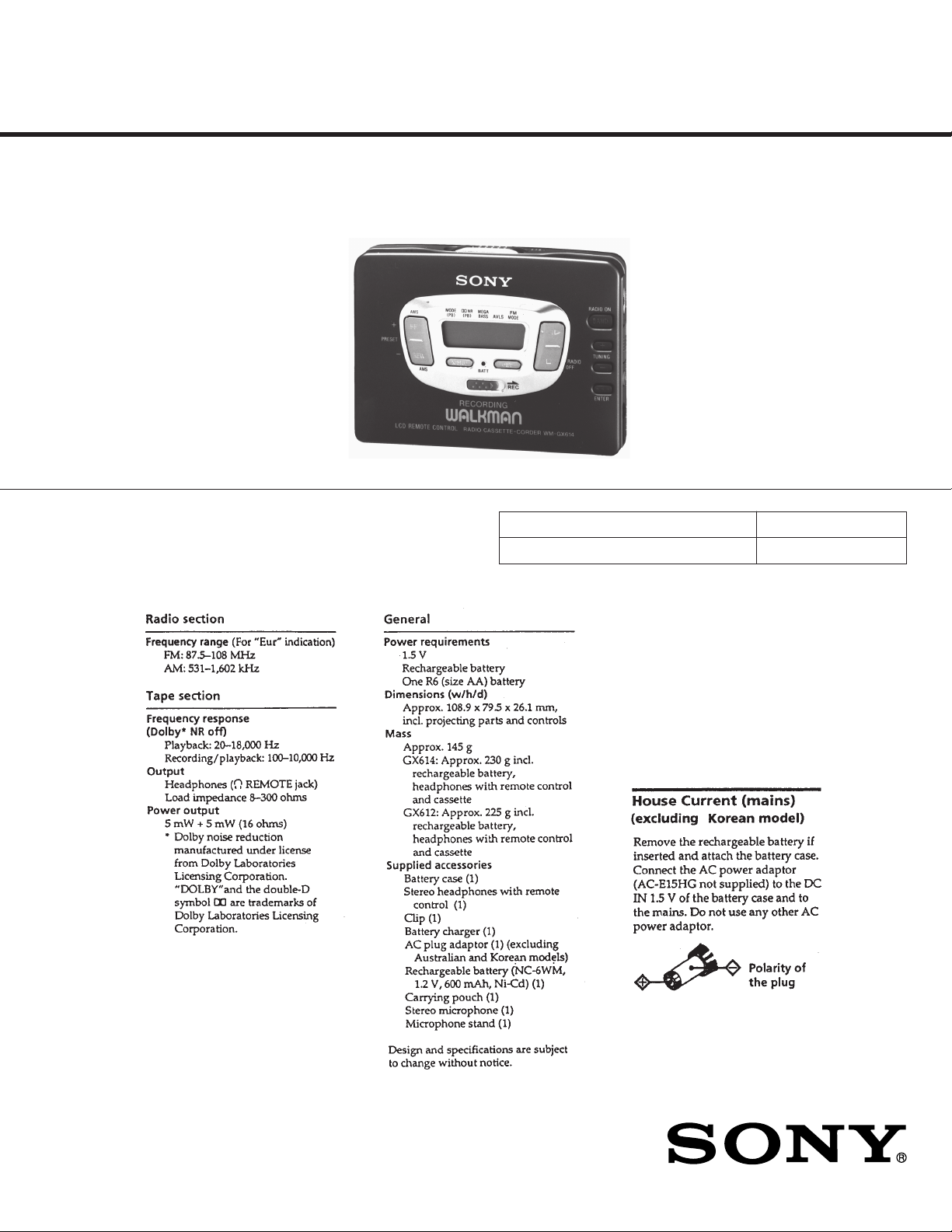
Photo : WM-GX614
SPECIFICATIONS
AEP Model
UK Model
E Model
Australian Model
Model Name Using Similar Mechanism NEW
Tape Transport Mechanism Type MF-WMGX614-112
9-960-414-12
2002A1600-1
© 2002.1
RADIO CASSETTE CODER
Sony Corporation
Personal Audio Company
Published by Sony Engineering Corporation
— 1 —
TABLE OF CONTENTS
Section Title Page
SECTION 1. SERVICE NOTE ................................. 3
SECTION 2. GENERAL .......................................... 5
SECTION 3. DISASSEMBLY
3-1. Cassette Lid ASSY and Case ASSY ................................. 7
3-2. Bracket ASSY and Cassette Holder ASSY ....................... 7
3-3. Tuner Board ....................................................................... 8
3-4. Main Board.........................................................................8
SECTION 4. MECHANICAL ADJUSTMENT .......... 9
SECTION 5. ELECTRICAL ADJUSTMENT ........... 9
SECTION 6. DIAGRAMS
6-1. IC Pin Functions
IC501 BA3641FV REC AMP ......................................... 11
IC701 MSM63120B System Control .............................. 11
IC702 SMC62L3A LCD Drive ....................................... 13
6-2. Printed Wiring Board — Tuner Section —.....................14
6-3. Schematic Diagram — Tuner Section —........................ 17
6-4. Schematic Diagram — Main Section — ......................... 21
6-5. Printed Wiring Board — Main Section —...................... 25
6-6. IC Block Diagrams .......................................................... 29
SECTION 7. EXPLODED VIEWS
7-1. Case Section ..................................................................... 33
7-2. Main Board Section ......................................................... 34
7-3. Mechanism Section (MF-WMGX614-112)..................... 35
SECTION 8. ELECTRICAL PARTS LIST............. 36
Notes on chip component replacement
• Never reuse a disconnected chip component.
• Notice that the minus side of a tantalum capacitor may be
damaged by heat.
Flexible Circuit Board Repairing
• Keep the temperature of the soldering iron around 270 °C
during repairing.
• Do not touch the soldering iron on the same conductor of
the circuit board (within 3 times).
• Be careful not to apply force on the conductor when solder-
ing or unsoldering.
SAFETY-RELATED COMPONENT WARNING !!
COMPONENTS IDENTIFIED BY MARK ! OR DOTTED
LINE WITH MARK ! ON THE SCHEMATIC DIAGRAMS
AND IN THE PARTS LIST ARE CRITICAL TO SAFE
OPERATION. REPLACE THESE COMPONENTS WITH
SONY PARTS WHOSE PART NUMBERS APPEAR AS
SHOWN IN THIS MANUAL OR IN SUPPLEMENTS
PUBLISHED BY SONY.
— 2 —
SECTION 1
SERVICE NOTE
[Service Mode]
Mode which enables the mechanism to be operated with the
MAIN board opened.
Photo sensor PH701 mounted on the MAIN board is used to
detect rotaion of the reels. Because it is mounted on the MAIN
board, when the MAIN board is being removed, rotation of the
reels cannot be detected and the auto-off/tape-end detector
circuit does not operate correctly.
F/R switch (S701) is also mounted on the MAIN board.
Therefore, without the MAIN board, the head cannnot be
placed in playback position, and power cannot be supplied to
the circuitry of the playback system.
When the MAIN board is being removed, follow the
procedures below, in order to check operation of the
mechanisms of the tape deck and to check voltages supplied to
each circuit.
1. Setting
1) Refer to “Disassembly” and remove the cabinet and open
the MAIN board.
2) Connect the MAIN board to the motor and plunger using a
jumper wire. Use “Extension tool (1-769-143-11)) (one set
10 tools)” to make connection simple.
3) Short-circuit the service mode land (BP2) by soldering.
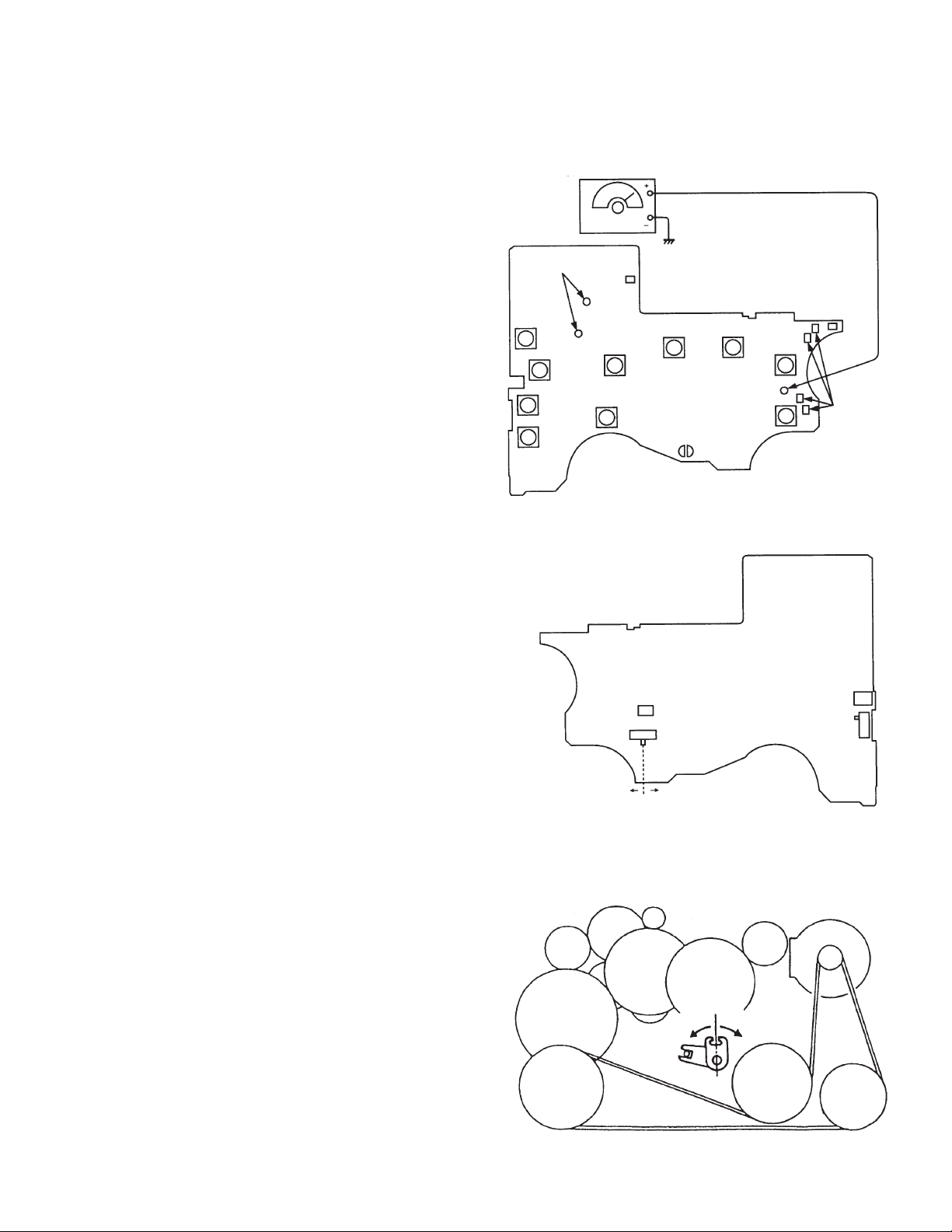
4) Apply a square wave signal to TP20. (See the figure on the
right.)
5) Supply 1.5V to the battery terminals (+) and (–) using a
DC power supply.
[MAIN Board]
— Side A —
AF OSCILLATOR
Connect to
plunger
S713
(ENTER)
S712
(TUNING –)
S704
S711
(TUNING +)
S707
(RADIO ON
BAND)
— Side B —
(REPEAT œ)
Battery Terminal (–)
S703
(RADIO OFF p)
SQUARE WAVE (SINE WAVE)
10Hz
3.5 dB (1.5V)
S709
(SET)
Service
mode land
S710
(MENU)
S705
(AMS FF
PRESET +)
S706
(AMS REW
PRESET –)
TP20
Battery
Terminal (+)
Connect to
motor
2. Preset State
This state must be set to set the PLAY, FF, and REW
modes.
1) Check that the lever (FR SW) is at the center and F/R
switch (S701) is at the center. If not, set the preset state as
follows.
2) Move the F/R switch (S701) according to the side faced by
the lever (FR SW).
3) Turn OFF the DC power supply switch once and then turn
it ON again so that the lever (FR SW) can be moved.
Move the F/R switch (S701) according to this timing and
set to the center.
3. FF REW Mode
1) Set the preset state and press the FF switch and REW
switch.
4. PLAY Mode
1) Set the preset state.
2) Press the ~ switch. The lever (FR SW) will move to the F
side once and then to the R side. Move the F/R switch
(S701) according to this timing to set the PLAY (R side)
mode. Press the ~ switch another time and move the F/R
switch (S701) according to the movement of the lever (FR
SW) to set the PLAY (F side) mode.
Note 1 : If the above cannot be performed, start again from
preset.
Note 2 : Use the remote control ~, &, FF, and REW switches
as much as possible. If the remote control is not
available, do not touch S703 to S706 with the hand
and use something with a round tip to press them.
R side
[Lever (FR SW)]
PH701
S701 F/R SWITCH
(FWD n STOP n REV)
F side
Center
R side
Lever (FR SW)
S702
(HOLDER
SWITCH)
S714
(C HOLD)
Center
F side
— 3 —
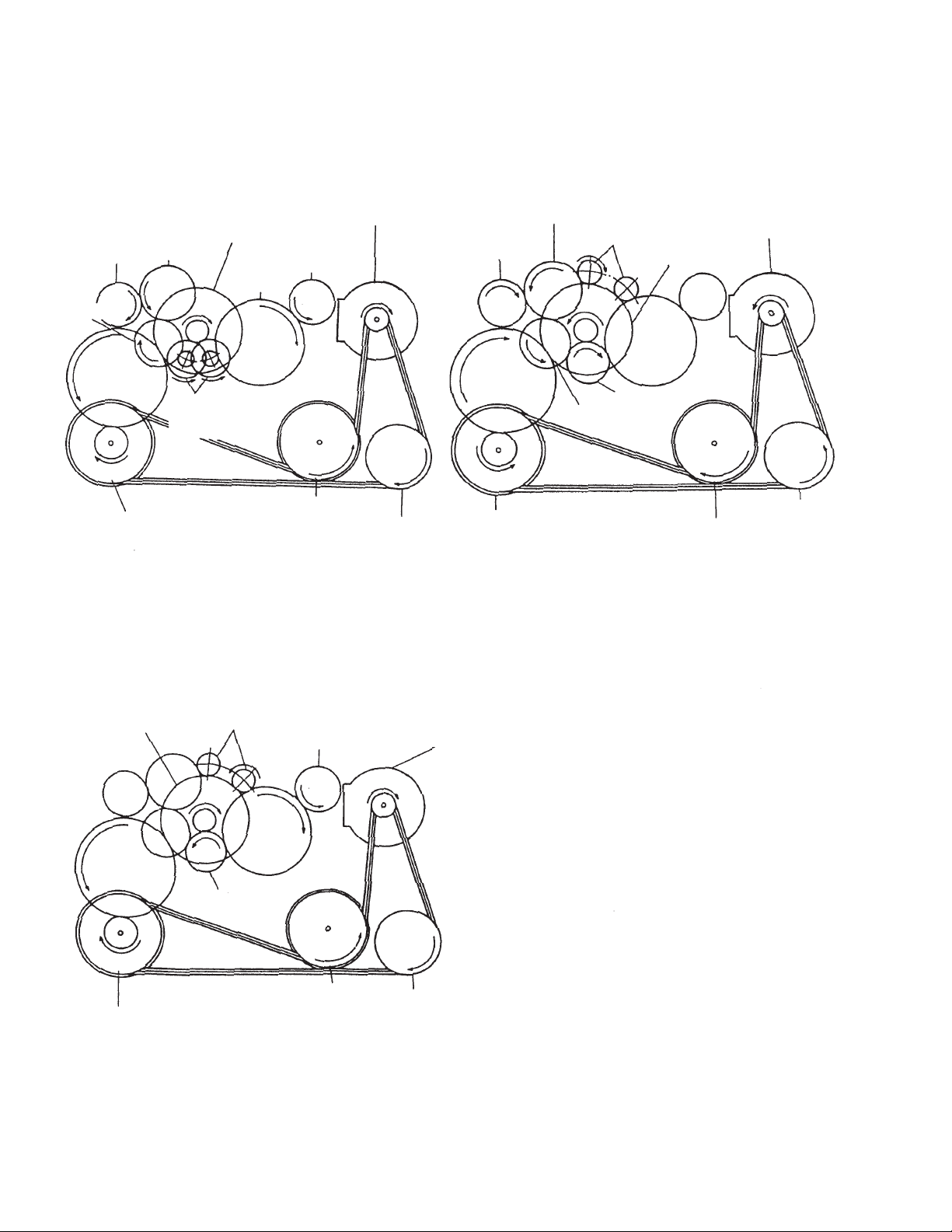
[Rotation system]
Rotation system during PLAY.
Reel table
(T side)
Gear (A)
Gear (K)
Capstan wheel (N)
assembly
Clutch assembly
Gear (B)
Gear (C)
Gear (NR)
(REV : Left side/
FWD : Right side)
Capstan wheel (R)
assembly
Reel table
(S side)
Motor pully
Pulley
(REVERSE)
Rotation system during REW.
Gear (B)
Reel table
(T side)
Gear (K)
Capstan wheel (N)
assembly
Gear (NR)
(REW : Left side)
Gear (NR)
Gear (A)
Capstan wheel (R)
assembly
Motor pully
Clutch assembly
Pulley
(REVERSE)
Rotation system during FF.
Gear (FR)
Clutch assembly
Gear (K)
Capstan wheel (N)
assembly
(FF : Right side)
Gear (NR)
Reel table
(S side)
Gear (C)
Capstan wheel (R)
assembly
Motor pully
Pulley
(REVERSE)
— 4 —
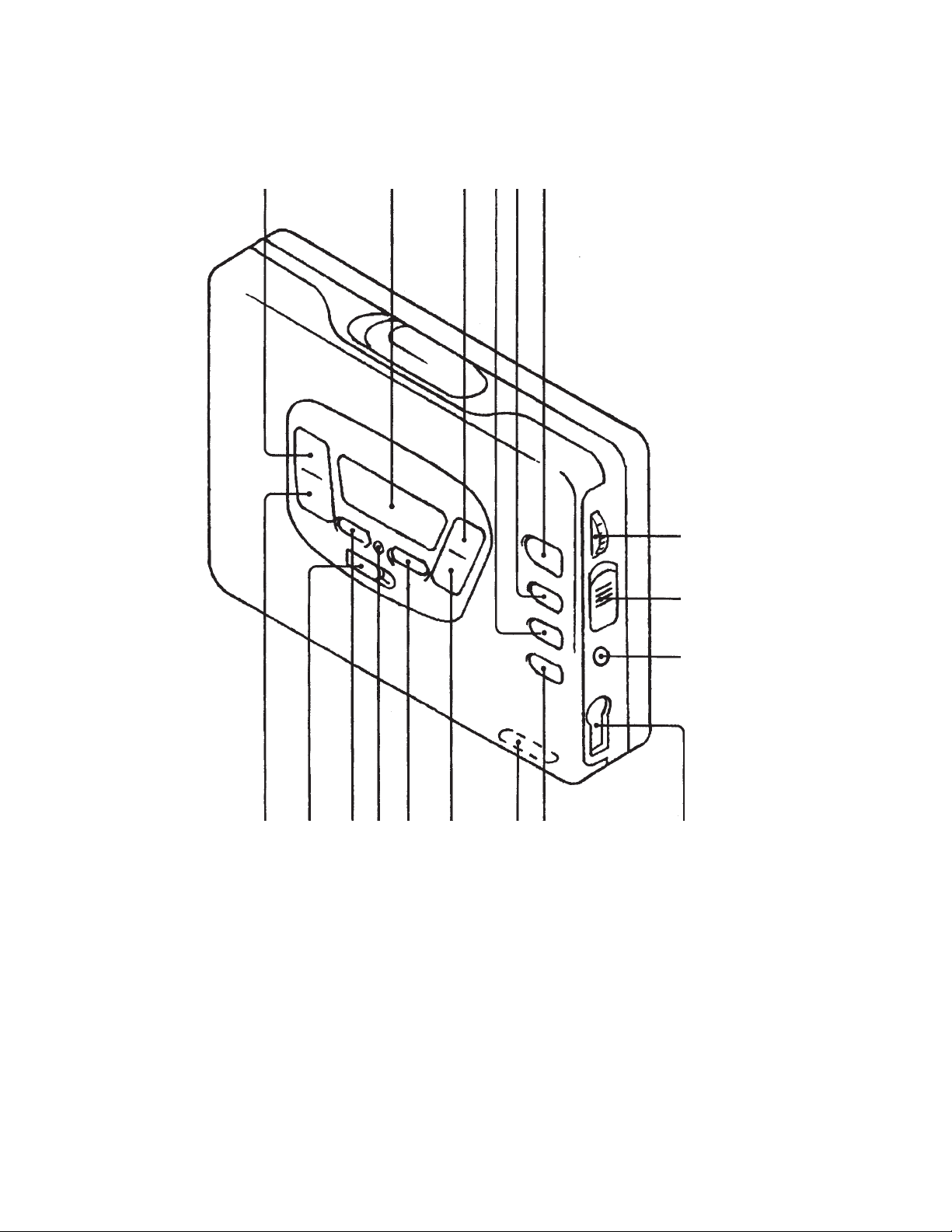
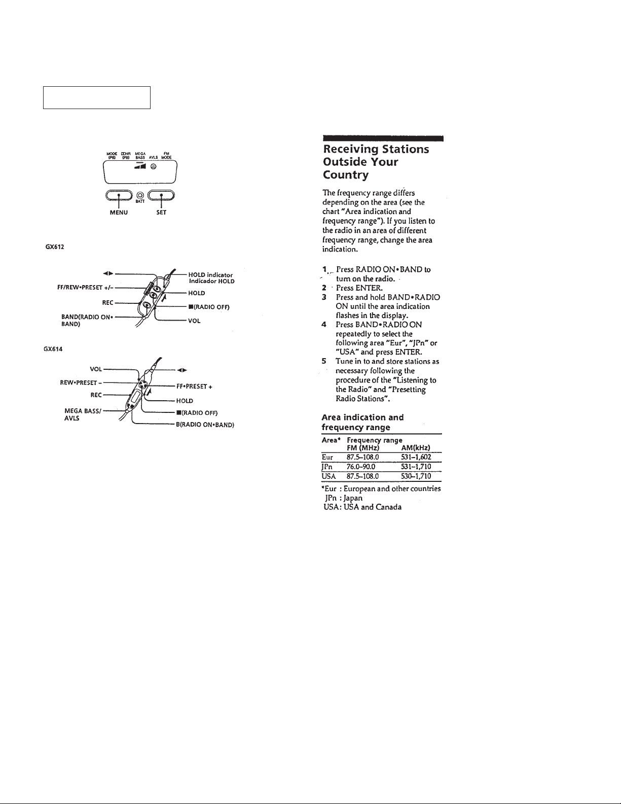
FUNCTION OF CONTROL
SECTION 2
GENERAL
2
1
!∞
!¢
!™!£
!¡
0
4
!§
3
1Display Window
2PRESET +/AMS FF button
3PRESET –/AMS REW button
4MENU button
5BATT indicater
6SET button
7p/RADIO OFF button
8ENTER button
92/REMOTE jack
• ILLUST LATION : WM-GX614 MODEL
5
6
7
!•
8
!¶
0HOLD knob
!¡VOLUME knob
!™RADIO ON/BAND button
!£TUNIG + button
!¢TUNIG – button
!∞œ/REPEAT button
!§REC switch
!¶ISS switch
!•MIC jack
9
— 5 —
This section is extracted
from instruction manual.
— 6 —
SECTION 3
DISASSEMBLY
Note : Follow the disassembly procedure in the numerical order given.
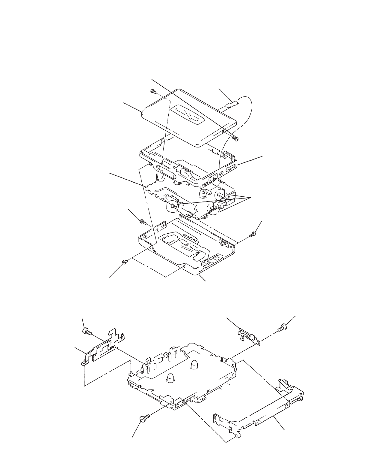
3-1. CASSETTE LID ASSY AND CASE ASSY
6
Two screws
(M1.4x2)
7
Cassette lid ASSY
9
Mechanism Block
5
TU flexible board
8
Reel ornament ASSY
2
Screw
(M1.4x3)
1
Two screws
(M1.4x3)
3-2. BRACKET ASSY AND CASSETTE HOLDER ASSY
1
Screw (M1.4)
2
Bracket ASSY
4
Case ASSY
4
Lock lever (B)
Note : Adjust the knob and the switch
position when installing.
3
Two screws
(M1.4x2)
3
Screw (M1.4)
5
Screw (M1.4)
— 7 —
6
Cassette holder ASSY
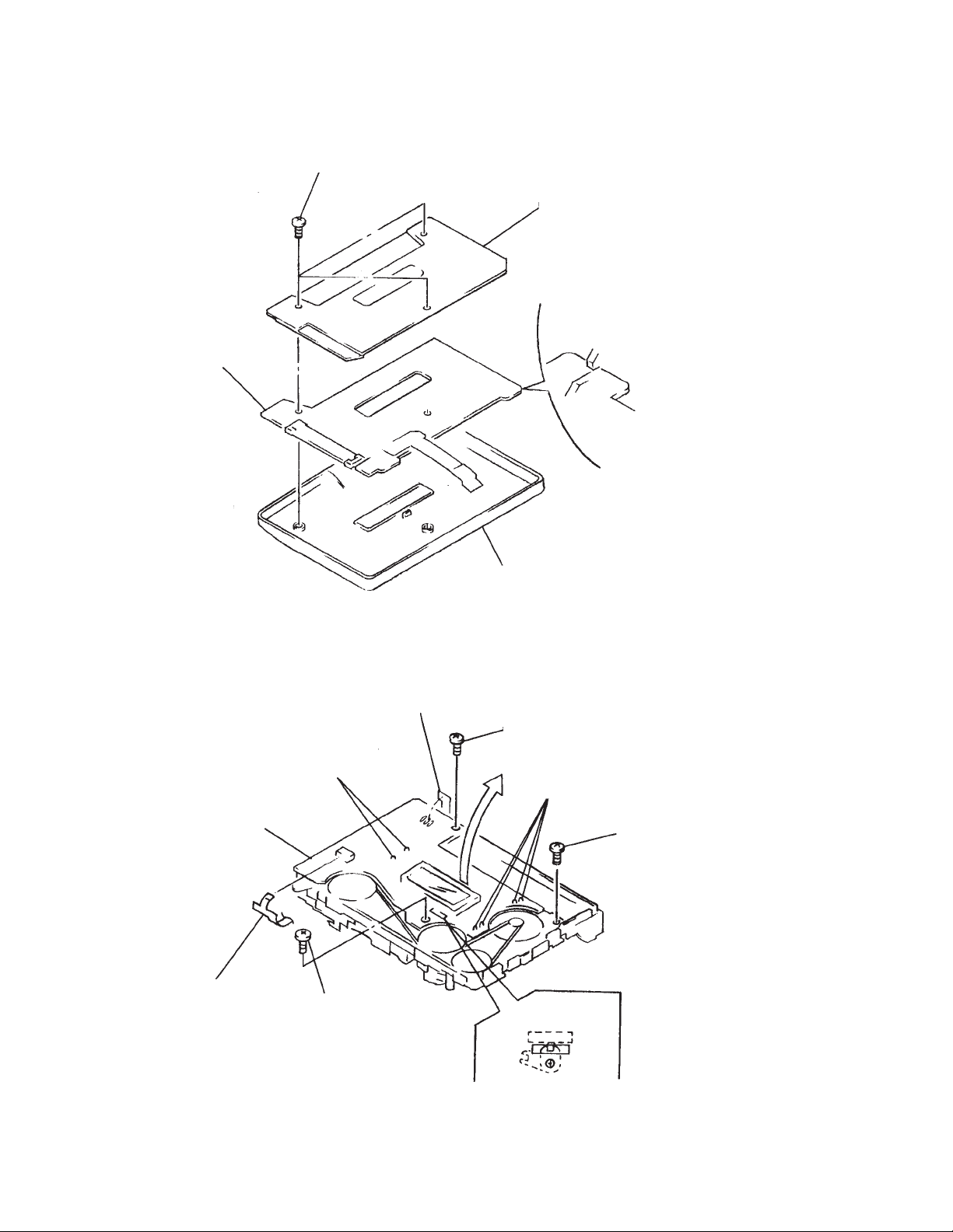
3-3. TUNER BOARD
3
TUNER board
1
Three tapping screws
2
4
Case ASSY
TU cover
Note for installation
3-4. MAIN BOARD
8
Remove the Main board
direction of arrow.
3
Flexible board
(Head)
4
Remove the solder of the
ATS flexible board.
2
Remove the solder of the
plunger solenoid.
7
Screw (M1.4x2)
5
Tapping screw
1
Remove the solder of the motor.
6
Tapping screw
S701
Lever (FR switch)
Note : Confirm if the switch lever
installs it self in the groove
of a lever (FR switch) for
assembling.
— 8 —
SECTION 4
SECTION 5
MECHANICAL ADJUSTMENT
PRECAUTION
1. Before adjusting, clean the following parts with a piece of
cotton moistened with alcohol.
playback head pinch roller
rubber belt capstan
2. Demagnetize the playback head using a head
demagnetizer.
3. Do not use a magnetized screwdriver for adjustments.
4. After adjusting, apply screw-locking compound onto the
adjusted parts.
5. Unless specified otherwise, use a specified voltage (1.3V)
to perform the adjustments.
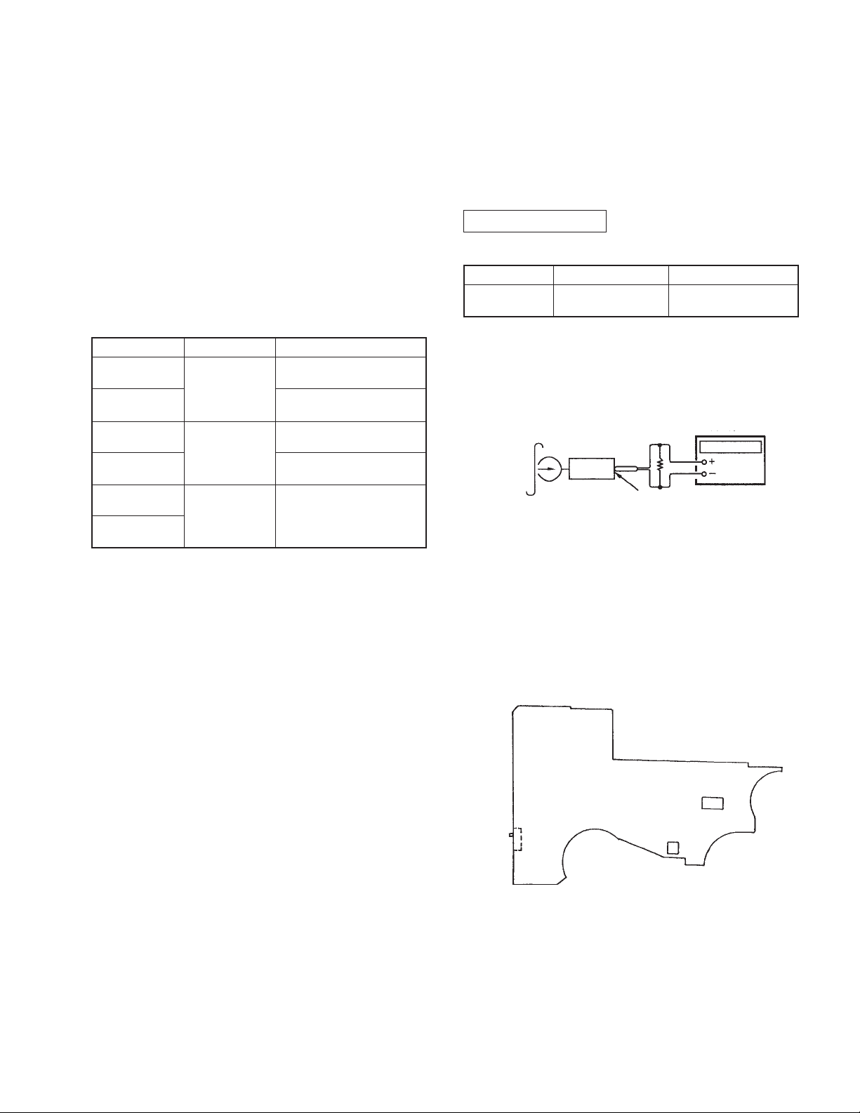
[Torque Measurement]
Mode
FWD
FWD
Back tension
REV
REV
Back tension
FF
REW
Torque Meter Meter Reading
18 — 33 g • cm
CQ-102C
0.5 — 3.0 g • cm
18 — 33 g • cm
CQ-102RC
0.5 — 3 g • cm
CQ-201B
More than 40 g • cm
ELECTRICAL ADJUSTMENT
PRECAUTION
1. Specified voltage : 1.3V.
2. Switch position
DOLBY NR switch : OFF
MEGA BASS switch: NORM
AVLS : OFF
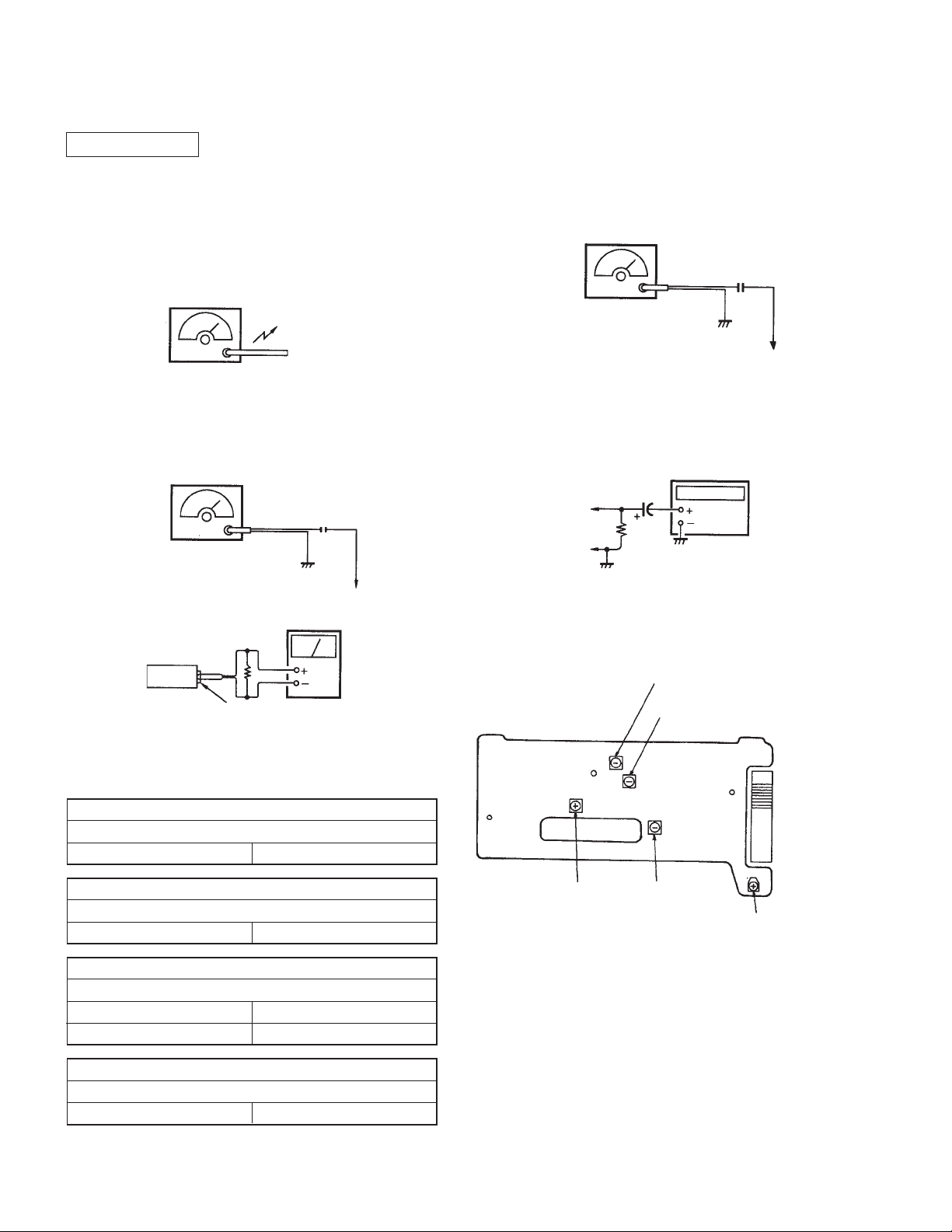
CASSETTE SECTION
Test tape
Type
[Tape Speed Adjustment]
Procedure :
Test tape
WS-48A
(3kHz, 0dB)
1. Playback WS-48A (tape center part) in the FWD state and
adjust RV601 so that the frequency counter reading
becomes 3000 ± 10 Hz.
2. Playback WS-48A (tape center) in the REV state.
Check that the frequency counter reading is within 2.5%
of the reading of step 1.
Signal Used for
16
Tape Speed AdjustmentWS-48A
frequency
counter
3 kHz, 0 dB
set
PHONES jack
Adjustment Point :
[MAIN BOARD] — Component side —
S714
(HOLD)
RV601
IC601
— 9 —
TUNER SECTION
[AM]
BAND switch : AM
NOTE: The adjustment should be performed setting the area indication
to “Eur”. (Refer to “Receiving Stations Outside Your Country”
on page 6.)
After the adjustment, reset the area indication as it was.
AM RF SSG
30% amplitude modulation by
400Hz signal
output level : as low as possible
Put the lead-wire
antenna close to
the set.
[FM]
BAND switch : FM
FM RF SSG
0.01µF
22.5kHz frequency deviation
by 400Hz signal.
output level : as low as possible
32
to ANT (TP1)
VTVM
[FM VCO Adjustment]
Procedure :
FM RF SSG
0.01µF
Carrier frequency : 98MHz
Modulation : no modulation
output level : 0.1V (100dB)
to ANT (TP1)
1. Connect frequency counter to the positions shown below.
2. Tune the to 98 MHz.
3. Adjust RV1 for 19 kHz ± 100Hz reading on the frequency
counter.
frequency
counter
TP23
(IC2 Pin !™)
IC2 Pin 9
1µF
100k
• Adjustment Parts Location
[TUNER BOARD] — Component side —
set
PHONES
• Repeat the procedures in each adjustment several times, and the
frequency coverage and tracking adjustments should be finally
done by the trimmer capacitors.
AM IF ADJUSTMENT
Adjust for a maximum reading on VTVM.
T2 450 kHz
AM VT VOLTAGE ADJUSTMENT
1.5 V
T1 531 kHz
AM TRACKING ADJUSTMENT
Adjust for a maximum reading on VTVM.
L5
CT1
FM IF ADJUSTMENT
Adjust for a maximum reading on VTVM.
L3 10.7 MHz
621 kHz
1,395 kHz
TP23
RV1 : VCO
T2 : AM IF
T1 : AM VT
L3 : FM IF
TP1
CT1 : AM TRACKING
L5 :
AM
TRACKING
— 10 —
 Loading...