

Sony WMFX-855 Service manual
WM-FX855
SERVICE MANUAL
Ver 1.3 2001.11
Photo: Black
Dolby noise reduction manufactured under license from
Dolby Laboratories Licensing Corporation.
“ DOLBY ” and the double-D symbol a are trademarks of
Dolby Laboratories Licensing Corporation.
SPECIFICATIONS
Tape player section and general
Frequency response (aNR switch off)
30–18,000 Hz
Output
Headphones (2 REMOTE jack)
Load impedance 8–300 ohms
Power output
3mW + 3mW at DC operation
Power requirements
1.5V DC
Rechargeable battery (NC-6WM), 1.2 V, 600mAh, Ni-Cd One R6
(size AA) battery
Battery life (Approx. hours)
Rechargeable NC-6WM
Fully charged
Playback 9
Radio/TV reception 9
E Model
Tourist Model
Model Name Using Similar Mechanism NEW
Tape Transport Mechanism Type MT-WMEX655-125
Dimensions
Approx. 108.7 × 80.0 × 23.5 mm (w/h/d)
Weight
Approx. 150 g (Main unit)
Approx. 210 g (incl. Headphones with remote control, Rechargeable battery NC-6WM, Tape (C-60HF)
Radio section
Frequency range
Tourist model
FM : 76–90MHz
AM : 531–1,710kHz
TV : 1–12ch (Except Korean model.)
Korean model (Area setting : Eur)
FM : 87.5–108MHz
AM : 531–1,602kHz
Sony alkaline LR6 (WM)
Playback 36
Radio/TV reception 29
Sony R6P (SR)
Playback 10
Radio/TV reception 9
Rechargeable NC-6WM
Sony alkaline LR6 (WM)
Used together
Playback 45
Radio/TV reception 36
9-923-252-12 Sony Corporation
2001K0500-1 Personal Audio Company
C 2001.11 Published by Sony Engineering Corporation
Design and specifications are subject to change without notice.
– Continued on next page –
RADIO CASSETTE PLAYER

TABLE OF CONTENTS
1. SERVICE NOTE ....................................................... 3
2. GENERAL ................................................................... 5
3. DISASSEMBLY ......................................................... 6
4. MECHANICAL ADJUSTMENT.......................... 8
5. ELECTRICAL ADJUSTMENT............................ 8
6. DIAGRAMS
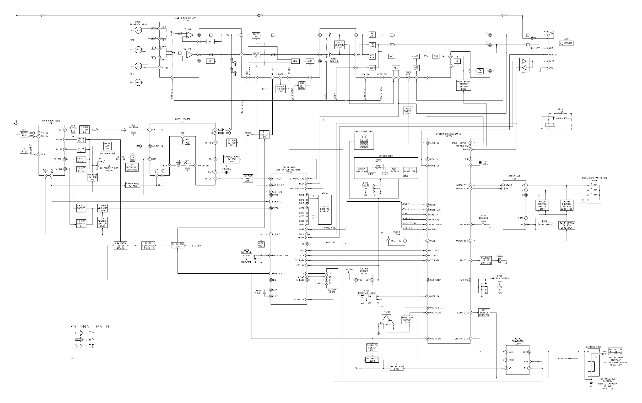
6-1. Block Diagram ................................................................ 11
6-2. Printed Wiring Board
– AUDIO Section – ......................................................... 14
6-3. Schematic Diagram
– AUDIO Section – ......................................................... 17
6-4. Schematic Diagram
– TUNER Section – ........................................................ 22
6-5. Printed Wiring Board
– TUNER Section – ........................................................ 25
6-6. IC Pin Function Description ........................................... 30
7. EXPLODED VIEWS ................................................ 34
8. ELECTRICAL PARTS LIST ............................... 37
Notes on chip component replacement
• Never reuse a disconnected chip component.
• Notice that the minus side of a tantalum capacitor may be damaged by heat.
Flexible Circuit Board Repairing
• Keep the temperature of the soldering iron around 270 ˚C during repairing.
• Do not touch the soldering iron on the same conductor of the
circuit board (within 3 times).
• Be careful not to apply force on the conductor when soldering
or unsoldering
SAFETY-RELATED COMPONENT WARNING!!
COMPONENTS IDENTIFIED BY MARK ! OR DOTTED
LINE WITH MARK ! ON THE SCHEMATIC DIAGRAMS
AND IN THE PARTS LIST ARE CRITICAL TO SAFE
OPERATION. REPLACE THESE COMPONENTS WITH
SONY PARTS WHOSE PART NUMBERS APPEAR AS
SHOWN IN THIS MANUAL OR IN SUPPLEMENTS PUBLISHED BY SONY.
– 2 –
SECTION 1
SERVICE NOTE
Service Mode
Mode for operating the mechanism section with the A UDIO board
opened.
1. Setting
1) Refer to “Disassembly”, and remov e the ca binet and open the
AUDIO board.
2) Connect the motor and plunger to the AUDIO board using
jumper wires. These can be connected easily with the use of
the extension tool (1-769-143-11) (ten in one set).
3) Turn ON the HOLDER switch (S706).
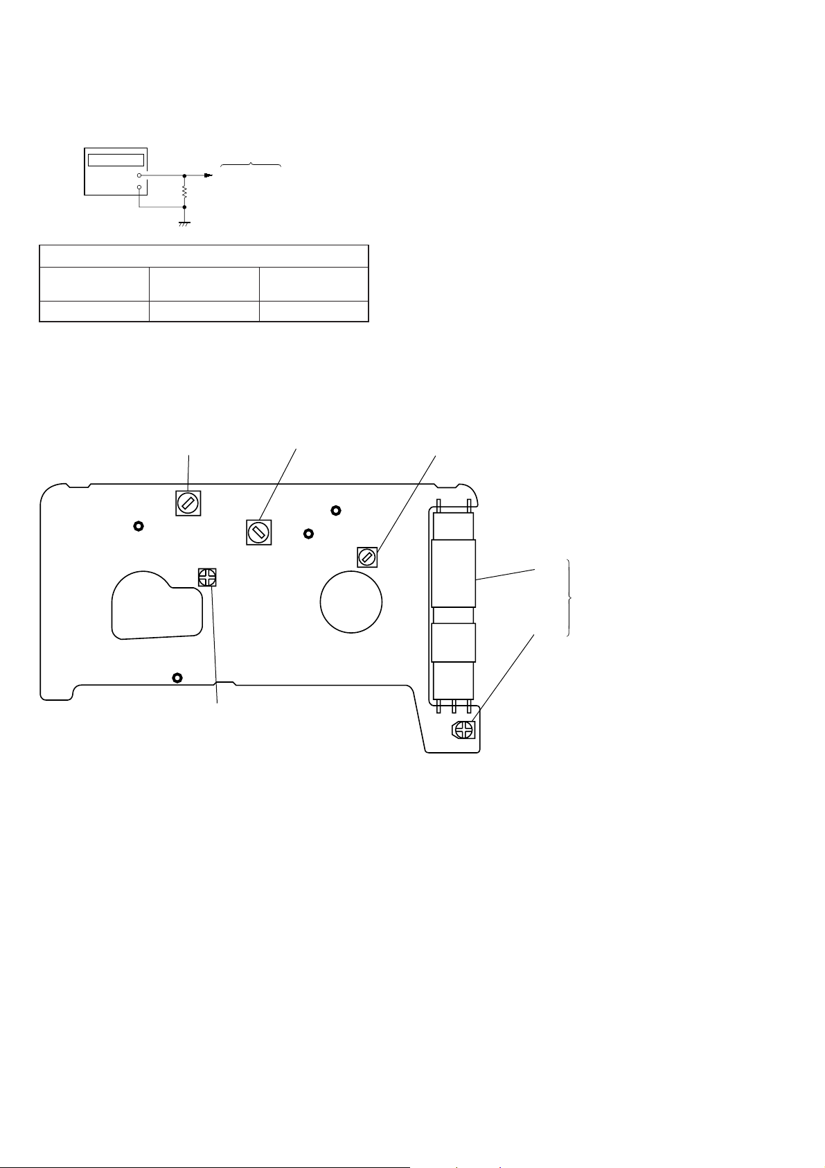
4) Input the square wave or sine wave to PH701. (See right figure.)
5) Supply 1.5 V to the ‘ and ’ terminals of the battery using a
regulated power supply.
2. Preset state
T o set the PLAY , FF, REW modes, the preset state must be set.
1) Check that the lever (FR SW) and FWD/RVS switch (S708)
are set to the center position. If not, set the preset state as follows.
2) Mo ve the FWD/RVS switch (S708) to the side which the lever
(FR SW) is facing.
3) The lever (FR SW) will move when the regulated power supply switch is set to OFF once and then set to ON. Move the
FWD/RVS switch (S708) according to this timing and set to
the center position.
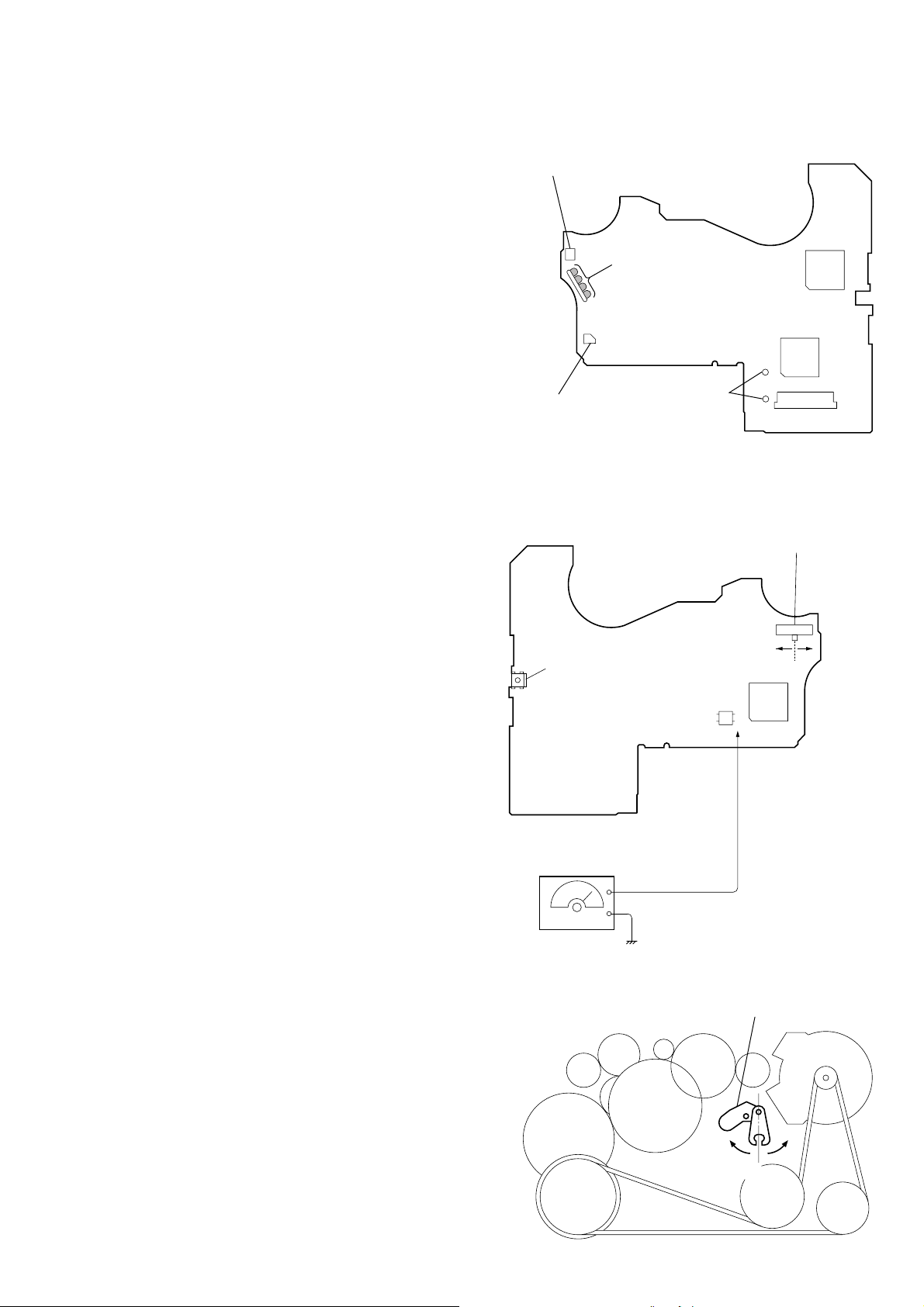
Audio Board
— Side A –
Battery terminal (—)
Battery
terminal (+)
— Side B —
Connect to motor
Connect to plunger
IC501
CN501
S708
FWD/RVS Switch
(FWD
←
STOP → RVS)
IC301
3. FF, REW Modes
1) Check that the preset state is set and press the FF and REW
switches.
4. PLAY mode
1) Check that the preset state is set.
2) Pressing the ª · switc h will move the le ver (FR SW) once
towards the F side and then to the R side. Moving the FWD/
R VS switch (S708) according to this timing will set the PLAY
mode (R side). Pressing the ª · switch another time and
moving the FWD/RVS switch (S708) according to the movement of the lever (FR SW) will set the PLAY ( F side) mode.
Note 1: If the above fails, perform from preset again.
Note 2: Use the ª ·, π, FF, REW switches on the remote
commander as much as possible. If no remote commander,
do not touch the switches with your hands, but using a
stick with a round tip.
Note 3: When using headphones, the timing for moving the S708
can be determined from the beep sound.
S706
(HOLDER Switch)
AF OSCILLATOR
Lever (FR SW)
PH701
AK
Sguare wave
(Sine wave)
10 Hz —3.5 dB
side F side R
Center
IC701
CE
lever (FR SW)
– 3 –
side F
side R
center
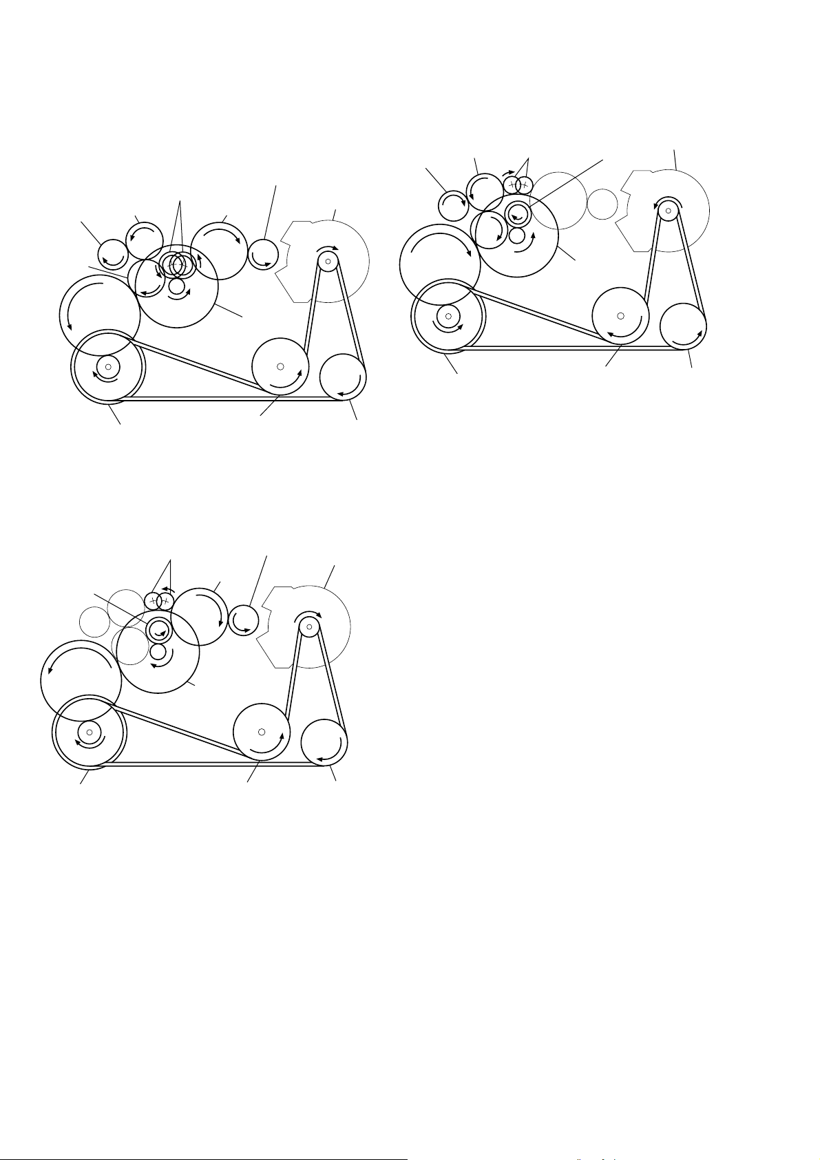
Rotation system
)
Rotation system during FF.
Rotation system during PLAY.
gear (NR)
(REW: right side/
FWD: left side)
gear (REEL)
(T side)
gear (TA)
gear (TB)
gear (Y)
flywheel (N) ass’y
flywheel (R) ass’y
Rotation system during REW.
gear (FR)
(REW: right side)
gear (S)
gear (NR)
gear (REEL)
(S side)
gear (S)
clutch ass’y (M)
gear (REEL)
(S side)
motor pulley
pulley (reverse)
motor pulley
gear (REEL)
(T side)
gear (Y)
gear (TB)
flywheel (N) ass’y
gear (FR)
(FF: left side)
gear (NR)
clutch ass’y (M)
flywheel (R) ass’y
motor pulley
pulley (reverse)
gear (Y)
flywheel (N) ass’y
clutch ass’y (M)
flywheel (R) ass’y
pulley (reverse
– 4 –
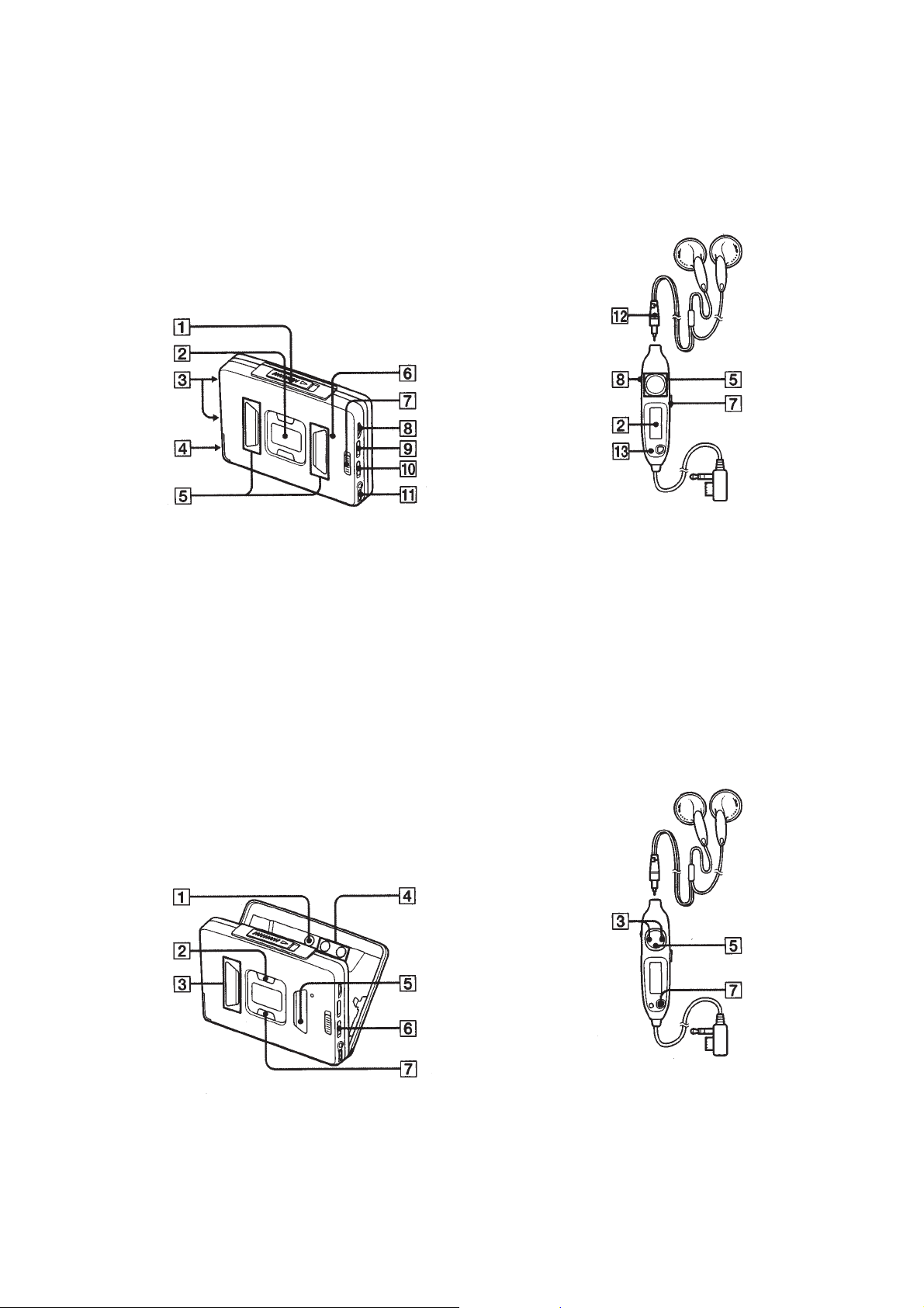
LOCATION AND FUNCTION OF CONTROLS
Tape player section and general
SECTION 2
GENERAL
• Main Unit
1 OPEN button
2 Information display
3 Contact for dry battery case
4 Rechargeable battery case
5 Tape operation buttons
6 BATT indicator
7 HOLD switch
• Headphones with Remote Control
Left Right
8 Main unit : VOLUME knob
Remote control : VOL knob
9 Åa (Tape direction),
BL SKIP (Blank skip) switch
!º a(DOLBY) NR switch
!¡ 2 REMOTE jack
!™ Micro plug
!£ SOUND/AVLS button
Radio section
• Main Unit
1 ENTER button
2 ASP (Auto Station Preset) button
3 PRESET +, – button
• Headphones with Remote Control
Left Right
4 TUNE +, – button
5 p, RADIO OFF button
6 FM ST/MONO switch
7 BAND, RADIO ON button
– 5 –
SECTION 3
K
DISASSEMBLY
• This set can be disassembled in the order shown below.
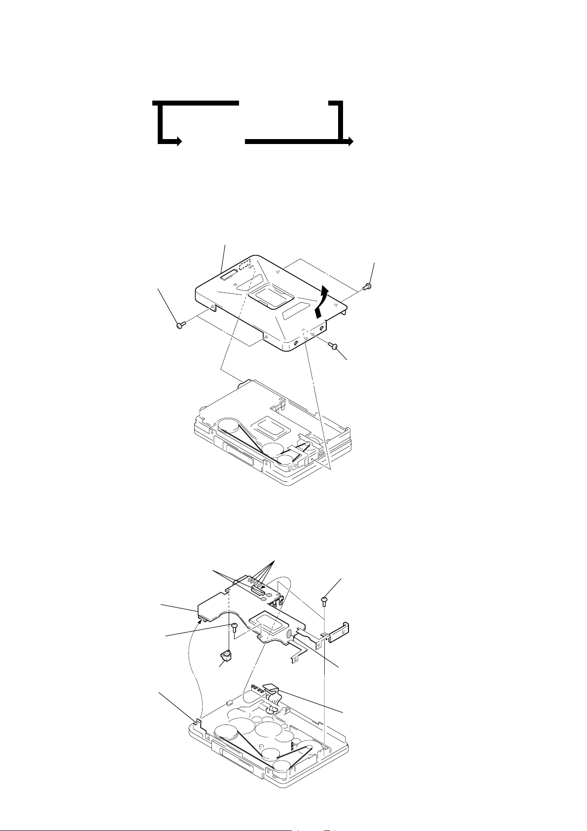
CASE ASS’Y
(page 6)
AUDIO BOARD
(page 6)
Note: Follow the disassembly procedure in the numerical order given.
LID ASS’Y CASSETTE
(page 7)
CASE ASS’Y
3
Remove the case ass’y
to direction of the arrow
1
two screws
(IB lock)
A
MECHANISM DEC
(page 7)
.
2
two screws
(IB lock)
2
screw (IB lock)
AUDIO BOARD
1
head flexible board
4
8
AUDIO board
Remove two solders.
7
screw
(IB lock)
9
sw cover
3
Remove four solders.
– 6 –
6
two screws
(M1.7
5
Remove four solders.
2
tuner flexible board
×
3.0)
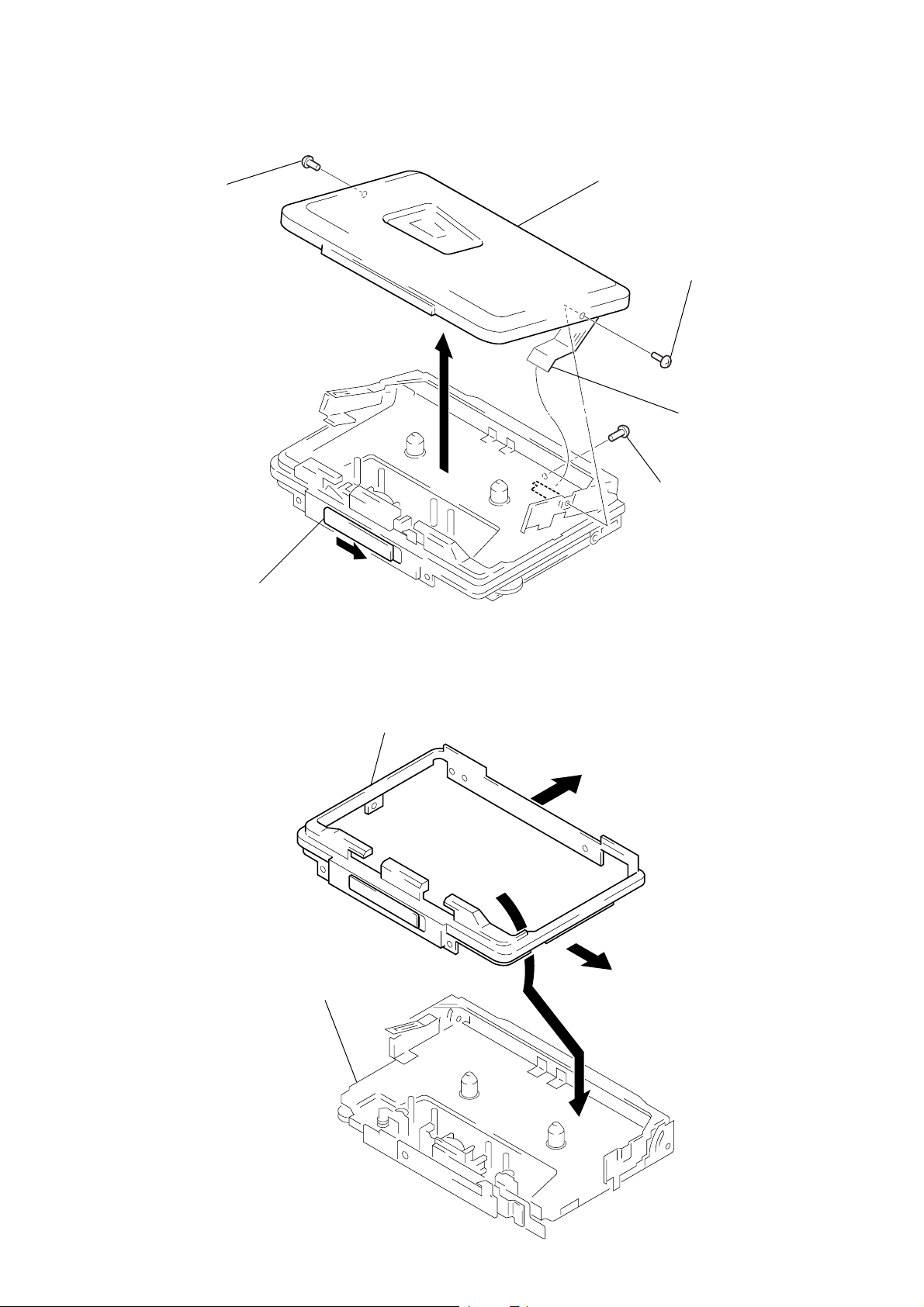
LID ASS’Y, CASSETTE
d
4
serrat (IB lock)
5
lid ass’y, cassette
3
4
serrat
(IB lock)
2
tuner flexible boar
screw
(IB lock)
1
Open the cassette lid.
MECHANISM DECK
ornament ass’y, reel
2
Remove the mechanism deck
to direction of the arrow
A
1
1
.
– 7 –
A
SECTION 4
Test tape
WS-48A
(3 kHz, 0 dB)
frequency counter
+
—
32
Ω
set
2
REOMTE jack
MECHANICAL ADJUSTMENTS
SECTION 5
ELECTRICAL ADJUSTMENTS
PRECAUTION
1. Clean the following parts with a denatured-alcohol-moistened
swab:
playback head pinch roller
rubber belts capstan
2. Demagnetize the playback head with a head demagnetizer.
(Do not bring the head demagnetizer close to the erase head.)
3. Do not use a magnetized screwdriver for the adjustments.
4. After the adjustments, apply suitable locking compound to the
parts adjusted.
5. The adjustments should be performed with the rated power
supply voltage (1.3 V) unless otherwise noted.
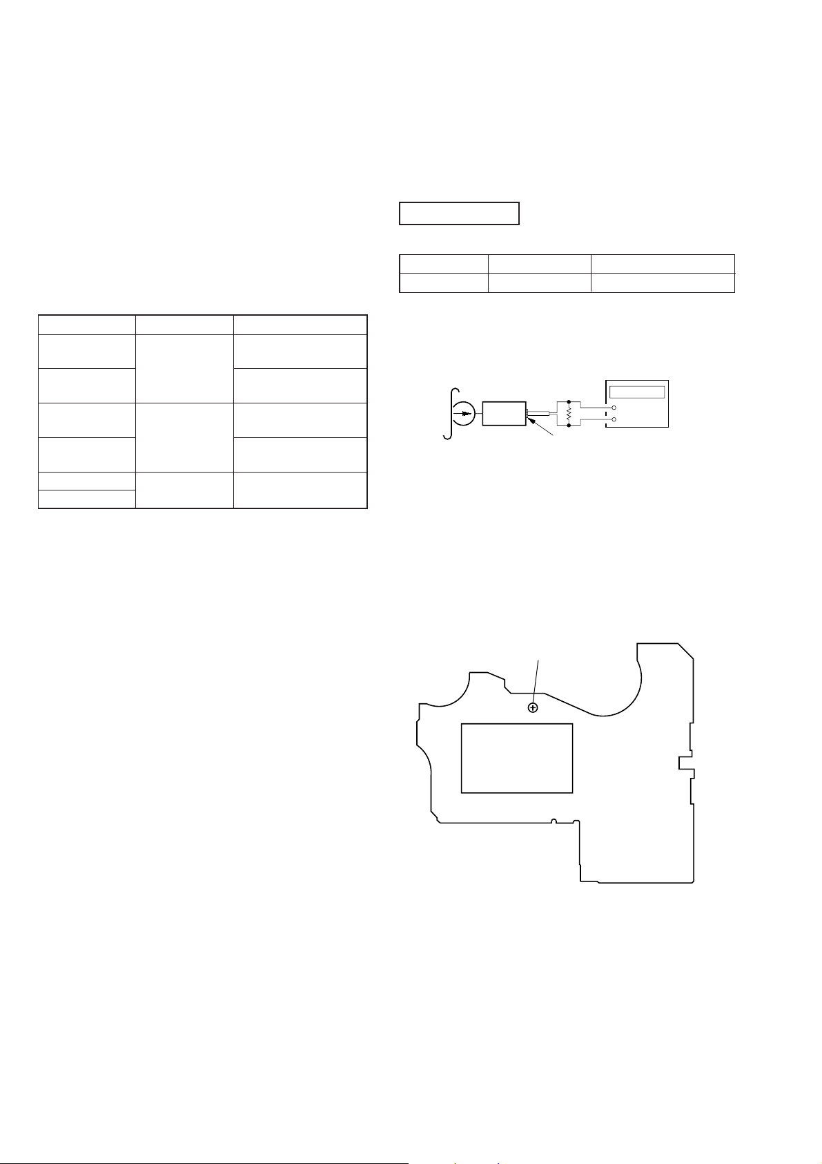
Torque Measurement:
Mode Torque meter Meter reading
FWD
FWD 0.7 – 2.0 g•cm
back tension (0.006 – 0.027 oz•inch)
REV
REV 0.7 – 2.0 g•cm
back tension (0.006 – 0.027 oz•inch)
FF
REW
CQ-102C
CQ-102RC
CQ-201B
18 – 30 g•cm
(0.25 – 0.41 oz•inch)
18 – 30 g•cm
(0.25 – 0.41 oz•inch)
more than 35g•cm
(more than 0.49 oz•inch)
PRECAUTION
1. Specified voltage : 1.3 V (DC)
2. Switch position
a NR switch : OFF
DIR MODE switch : a
TAPE SECTION
Test tape
Type Signal Used for
WS-48A 3 kHz, 0 dB Tape Speed Adjustment
Tape Speed Adjustment
Procedure:
1. Playback WS-48A (tape center part) in the FWD state and adjust R V601 so that the frequency counter reading becomes 3,015
± 10 Hz.
2. Playback WS-48A (tape center) in the REV state.
Check that the frequency counter reading is within 2.5% of the
reading of step 1.
Adjutment Point:
AUDIO BOARD – Side A –
RV601
ND501
– 8 –
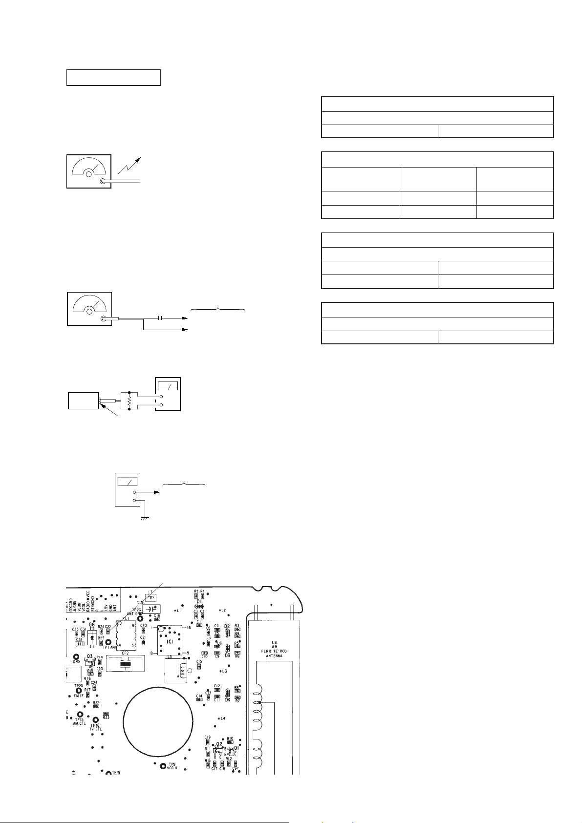
TUNER SECTION
)
r
AM SECTION
Setup:
BAND switch: AM
AM RF signal
generator
400 Hz 30 %
AM modulation
Output level: as low as possible
Put the lead-wire
antenna close to
the set.
• For the tracking adjustment, repeat is 2 or 3 times, then end
with adjustment of trimmer capacitor.
AM IF ADJUSTMENT
Adjust for a maximum reading on level meter.
T2 450 kHz
AM FREQUENCY COVERAGE ADJUSTMEN
Adjusting device Frequency display
Digital Voltmeter
reading
T1 531 kHz 1.3 ± 0.05 V
Confirm 1,710 kHz 7.95 ± 0.5 V
FM SECTION
Setup:
BAND switch: FM
FM RF signal
generator
µ
F
0.01
1 kHz 100 % FM modulation
frequency devition
Output level: as low as possible
set
±
75 kHz
level mete
32
Ω
2
REMOTE jack
Connection:
AM Frequency coveage adjustment
digital voltmeter
TUNER Board
—
+
TP21 (VT)
(see page10)
TUNER Board
TP1 (ANT)
TP23 (ANT GND
(see page 10)
AM TRACKING ADJUSTMENT
Adjust for a maximum reading on level meter.
L8 621 kHz
CT1 1,404 kHz
FM IF ADJUSTMENT
Adjust for a maximum reading on level meter.
L5 10.7 MHz
Caution:
Before the FM measurement, remove a chip ceramic capacitor C22
in the ANT line. Reconnect it after measure ment.
[TUNER Board]
C22
– 9 –
VCO Adjustment
)
connection:
frequency counter
TUNER Board
+
—
150 k
Ω
VCO Adjustment
Adjusting device Frequency display
RV1 78.00 MHz 19.00 kHz ± 0.05 kHz
• Adjusting Location
TP25 (19 kHz
Frequency counter
reading
[TUNER Board]
AM IF Adjustment
TP25
(19 kHz)
TP21
(VT)
VCO Adjustment
T2
RV1
AM Frequency coverage
T1
Adjustment
TP23
(ANT GND)
TP1
(ANT)
L5
FM IF Adjustment
L8
AM
Tracking
Adjustment
CT1
– 10 –
 Loading...