

Sony WMFS-593 Service manual
WM-FS593/FS595
SERVICE MANUAL
Ver 1.3 1999. 06
With SUPPLEMENT-1
(9-924-906-81)
Photo : WM-FS593
SPECIFICATIONS
Radio section
Frequency range FM: 87.5 - 108 MHz
AM: 530 - 1,710 kHz (US, Canadian,
Central and South America)
531 - 1,602 kHz (Except US,
Canadian, Central and South America)
US Model
Canadian Model
WM-FS593/FS595
AEP Model
E Model
WM-FS593
Model Name Using Similar Mechanism NEW
T ape Transport Mechanism Type MF-WMFS593-147
Tape section
Frequency response (Dolby NR off)
Playback: 30 - 14,000 Hz
Output 2 (Headphones/earphones) jack
Load impedance 8 - 300 ohms
General
Power requirements 3 V
Two R6 (size AA) batteries
Dimensions (w/h/d) Approx. 96.5 × 130.6 × 47.8 mm
(3 7/8 × 5 1/4 × 1 15/16 inches) incl.
projecting parts and controls
Mass Approx. 295 g (10.5 oz) / Approx.
370 g (13.1 oz) incl. batteries and
a cassette
Supplied accessories Stereo headphones or Stereo
earphones (1)
Belt clip (1)
Flasher (1) (FS595 only)
Sony CR2025 lithium battery (1)
(FS595 only)
Design and specifications are subject to change without
notice.
Dolby noise reduction manufactured under license from Dolby Laboratories Licensing Corporation.
“DOLBY” and the double-D symbol a are trademarks of Dolby
Laboratories Licensing Corporation. (WM-FS595 only)
Notes on Chip Component Replacement
• Never reuse a disconnected chip component.
• Notice that the minus side of a tantalum capacitor may be dam-
aged by heat.
Flexible Circuit Board Repairing
• Keep the temperature of the soldering iron around 270˚C during
repairing.
• Do not touch the soldering iron on the same conductor of the
circuit board (within 3 times).
• Be careful not to apply force on the conductor when soldering
or unsoldering.
RADIO CASSETTE PLAYER
MICROFILM
– 1 –

TABLE OF CONTENTS
1. SERVICE NO TE
1-1. Moisture Resistant Treatment ............................................. 3
2. GENERAL
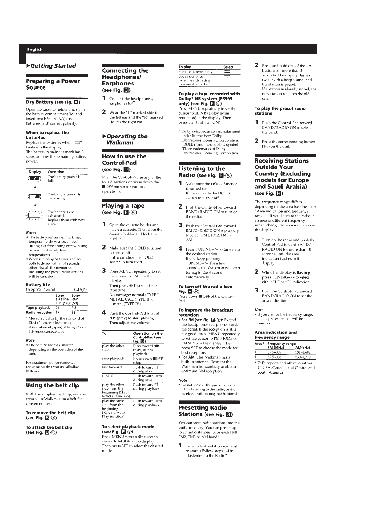
Getting Started ........................................................................ 6
Operating the Walkman .......................................................... 6
Additional Information ........................................................... 7
3. DISASSEMBLY
3-1. Display Board .....................................................................8
3-2. Mechanism Block ...............................................................8
3-3. Main Board .........................................................................9
3-4. Mechanism Deck.................................................................9
3-5. Headphone Board.............................................................. 10
3-6. Control Board.................................................................... 10
4. MECHANICAL ADJUSTMENTS............................11
5. ELECTRICAL ADJUSTMENTS .............................11
6. DIAGRAMS
6-1. Block Diagram .................................................................. 13
6-2. Printed Wiring Boards –Main Section– ............................ 15
6-3. Schematic Diagram –Main Section–.................................17
6-4. Printed Wiring Board –Display Section– .......................... 20
6-5. Schematic Diagram –Display Section–.............................21
6-6. IC Pin Description............................................................. 24
7. EXPLODED VIEWS
7-1. Cassette Holder Section .................................................... 26
7-2. Rear Cabinet Section......................................................... 27
7-3. Mechanism Deck Section..................................................28
8. ELECTRICAL PARTS LIST.....................................29
– 2 –
SECTION 1
SERVICE NOTE
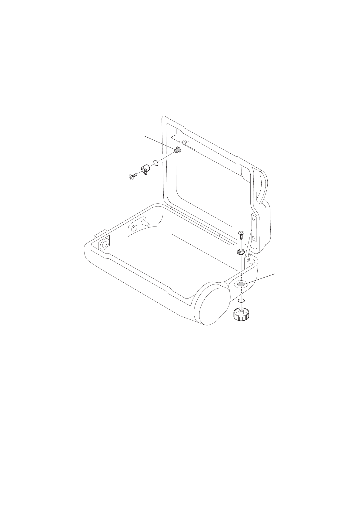
1-1. MOISTURE RESISTANT TREATMENT
Be sure to perform the following work when the HOLD knob and
VOL knob have been replaced in servicing:
Apply SONY grease SGL-505 (7-662-010-04) to the HOLD knob
and V OL knob at the points specif ied in the f igur e with an applicator or other means.
grease applying
point (HOLD knob)
grease applying
point (rear cabinet)
– 3 –
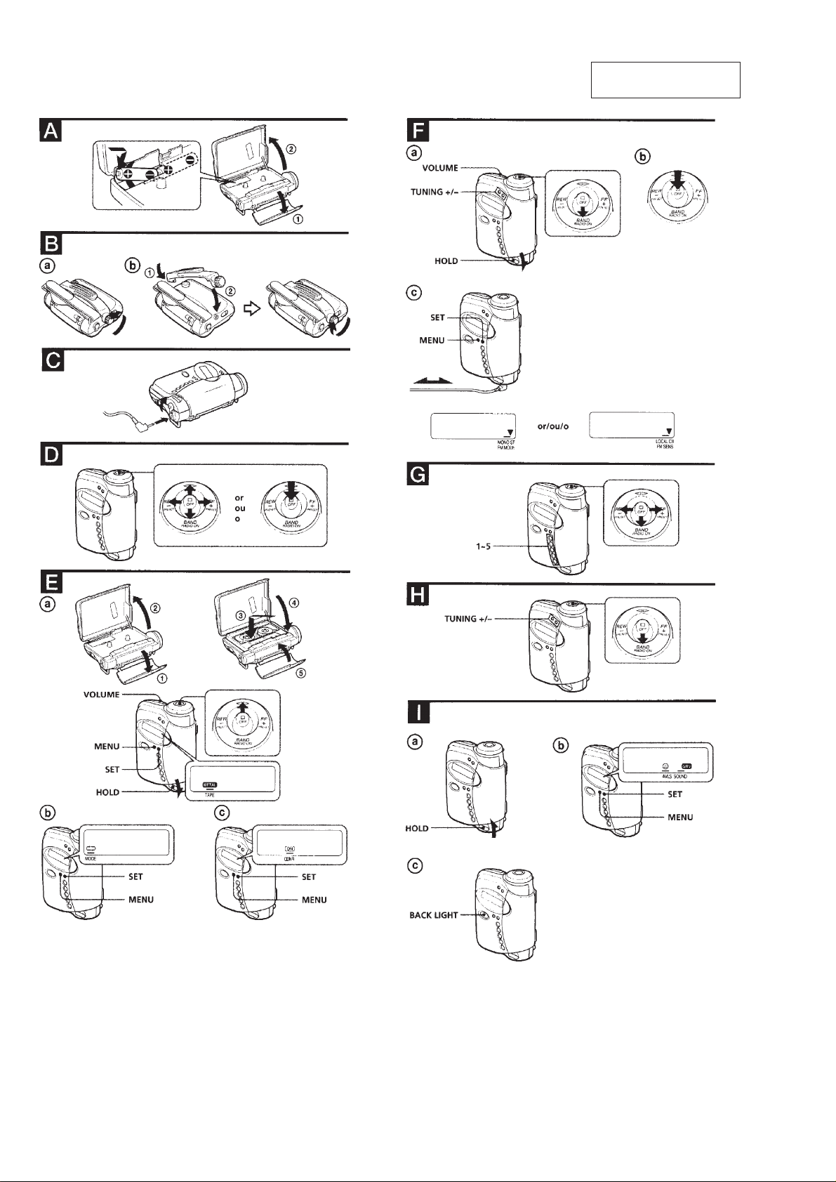
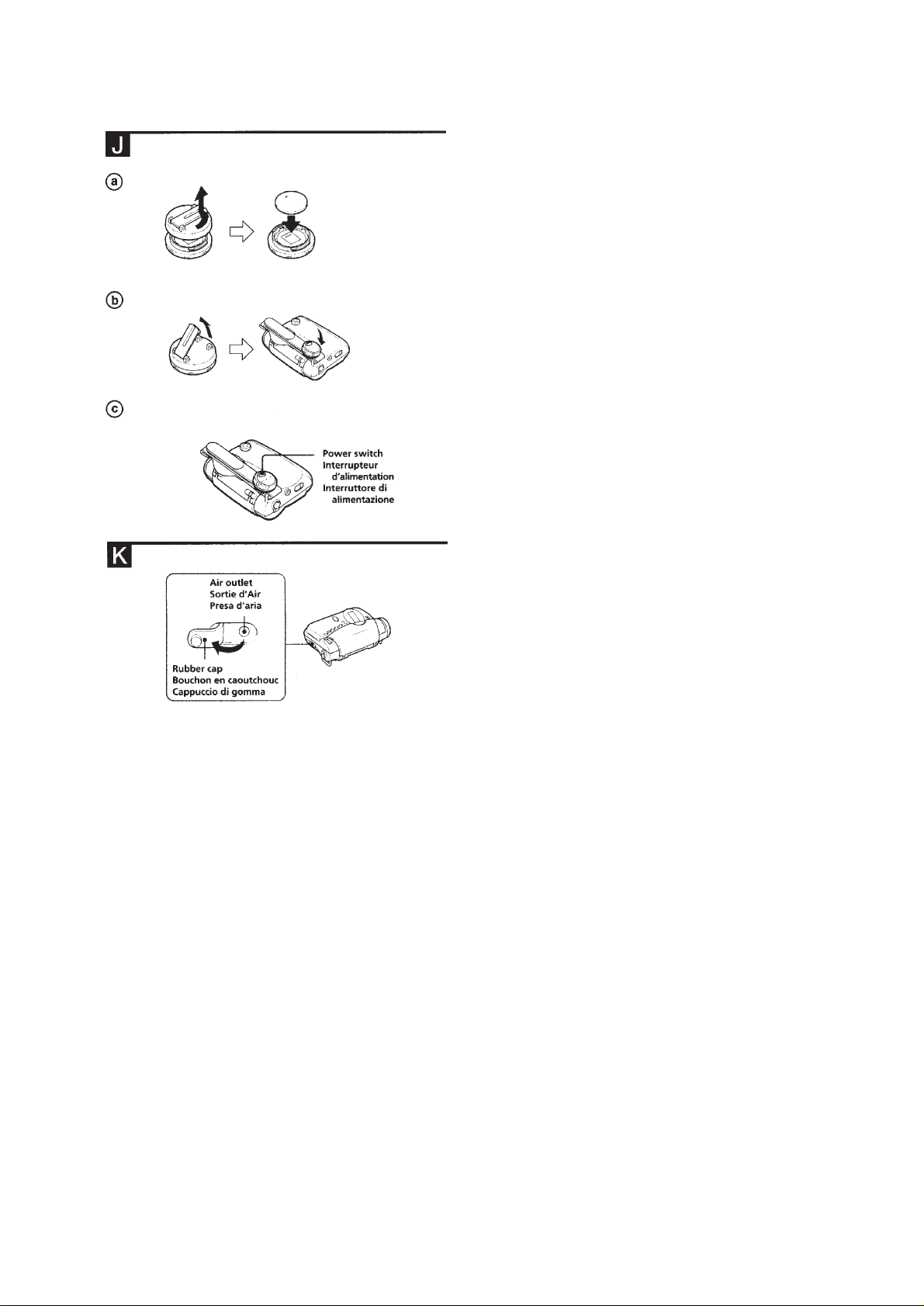
SECTION 2
GENERAL
This section is extracted
from instruction manual.
– 4 –
– 5 –
– 6 –
– 7 –
SECTION 3
DISASSEMBLY
• The equipment can be removed using the following procedure.
Set / Display board / Mechanism block Main board / Mechanism deck
Headphone board
Control board
Note : Follow the disassembly procedure in the numerical order given.
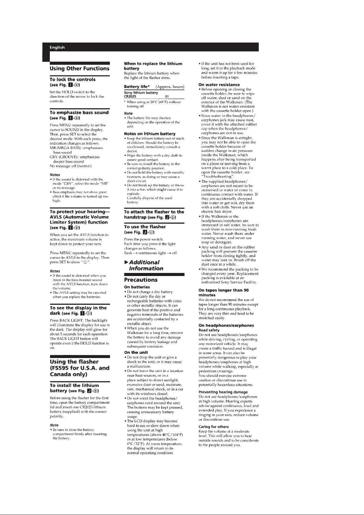
3-1. DISPLAY BOARD
5
B 1.7x4
1
claws
6
DISPLAY board
3-2. MECHANISM BLOCK
7
Removal the
three solders.
2
cover
1
B 1.7x8
5
4
CN702
claw
B 1.7x8
2
3
3
CN701
claw
mechanism
block
– 8 –
4
6
connector
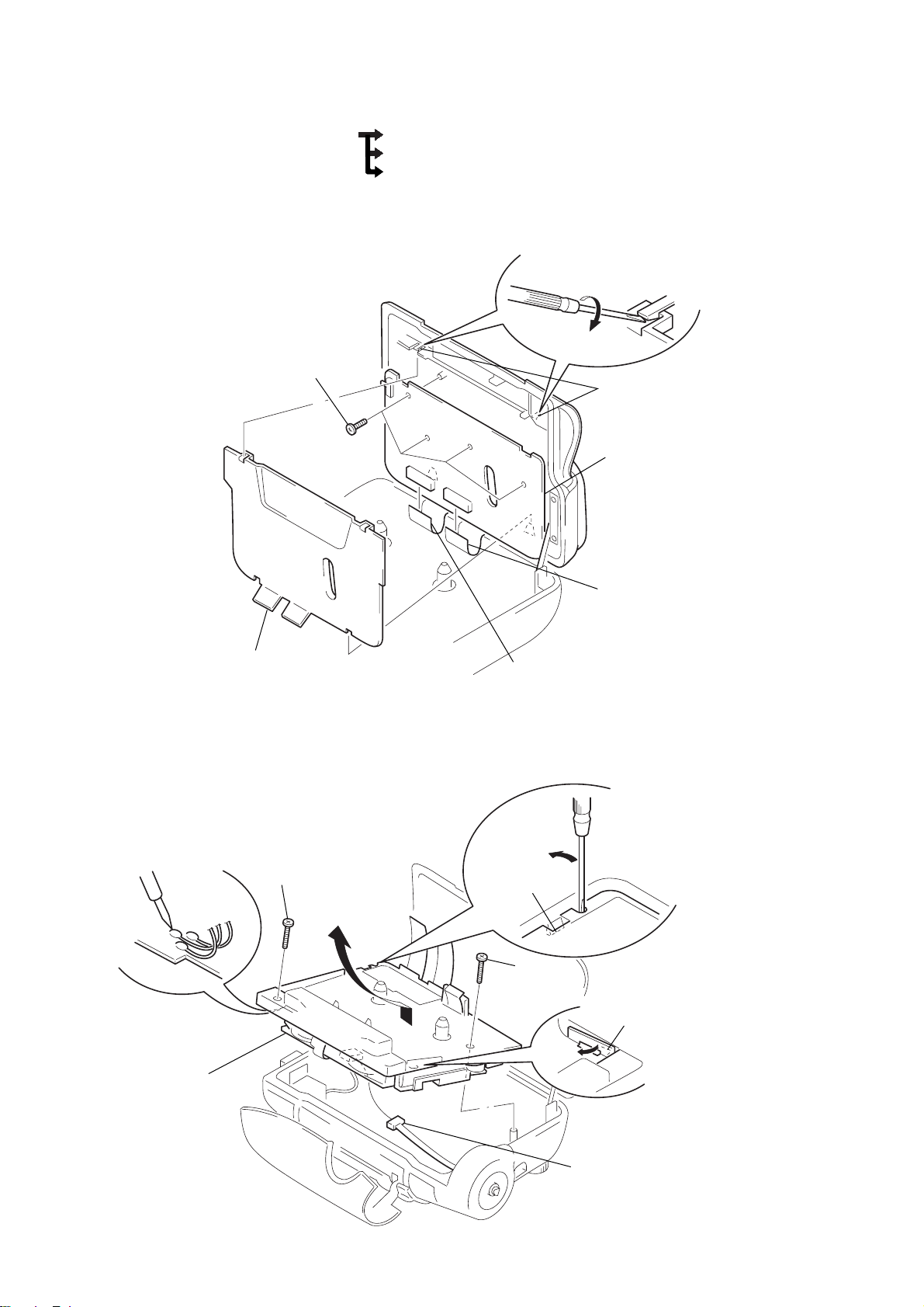
3-3. MAIN BOARD
5
MAIN board
3
screw
4
claws
2
Removal the
four solders.
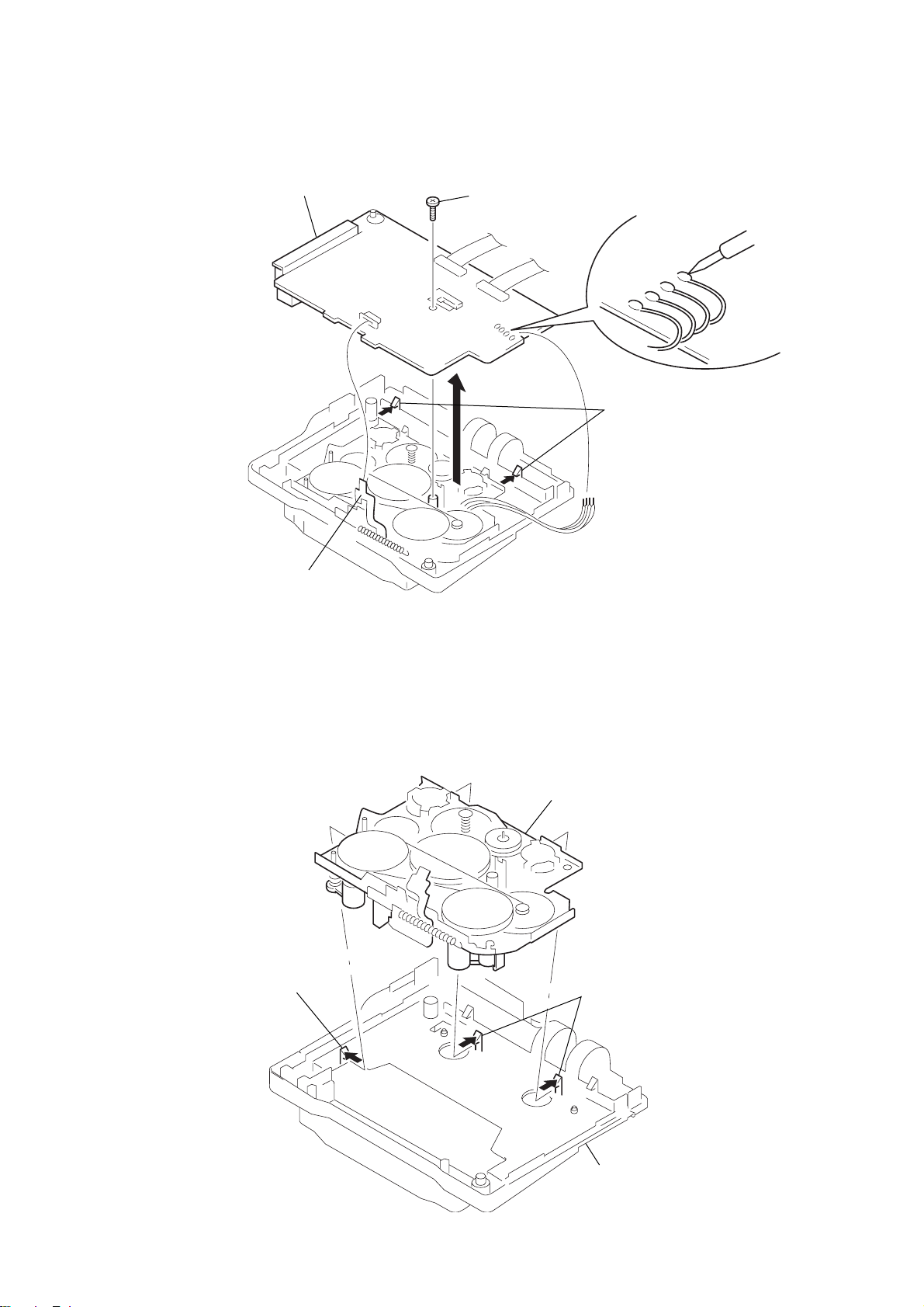
3-4. MECHANISM DECK
1
1
CN305
claw
mechanism deck
(MF-WMFS593-147)
2
claws
– 9 –
chassis
 Loading...