

Sony WMFS-421 Service manual
WM-FS421
SERVICE MANUAL
Ver 1.0 2001. 04
SPECIFICATIONS
• Frequency range
FM: 87.5 - 108 MHz
AM: 530 - 1 710 kHz (North, Central and South America)
531 - 1 602 kHz (Other countries)
• Power requirements
3 V DC batteries R6 (size AA) × 2
• Dimensions (w/h/d)
Approx. 107.3 × 123.3 × 51.5 mm (4
excluding projecting parts and controls
• Mass
Approx. 282 g (10.0 oz) (main unit only)
• Supplied accessories
Stereo headphones or earphones (1)
Belt clip (1)
Design and specifications are subject to change without notice.
Battery life (approximate hours) (JEITA*)
Sony alkaline LR6 (SG)** 32 40
Sony R6P (SR) 9 14
Tape Radio
playback reception
E Model
Model Name Using Similar Mechanism NEW
T ape Transport Mechanism T ype MF-WMFS421-114
1
⁄4 × 4 7⁄8 × 2 1⁄8 inches),
9-873-121-11
2001D1600-1
© 2001.4
* Measured value by the standard of JEITA (Japan Electronics
and Information Technology Industries Association). (Using
a Sony HF series cassette tape)
**When using Sony LR6 (SG) “STAMINA” alkaline dry
batteries (produced in Japan).
Note
•The battery life may be shorter depending on the
operating condition, the surrounding temperature
and battery type.
Sony Corporation
Personal Audio Company
Shinagawa Tec Service Manual Production Group
RADIO CASSETTE PLAYER
WM-FS421
TABLE OF CONTENTS
1. GENERAL ·········································································· 2
2. SERVICE NOTE ······························································· 3
3. DISASSEMBLY
3-1. Main Assy······································································4
3-2. Chassis Sub Assy··························································· 5
3-3. MAIN Board and Mechanism Deck······························ 5
3-4. Belt ················································································ 6
3-5. Head, Magnetic (HP701)··············································· 6
4. MECHANICAL ADJUSTMENT ·································· 7
5. ELECTRICAL ADJUSTMENT ···································· 7
6. DIAGRAMS
6-1. IC Block Diagrams ······················································ 10
6-2. Block Diagram ···························································· 11
6-3. Printed Wiring Board··················································· 12
6-4. Schematic Diagram ····················································· 13
6-5. IC Pin Function Description········································ 14
7. MEXPLODED VIEWS
7-1. Cabinet Assy Section ··················································· 15
7-2. MAIN Board Section ·················································· 16
7-3. Mechanism Deck Section-1
(MF-WMFS421-114) ·················································· 17
7-4. Mechanism Deck Section-2
(MF-WMFS421-114) ·················································· 18
8. ELECTRICAL PPARTS LIST ···································· 19
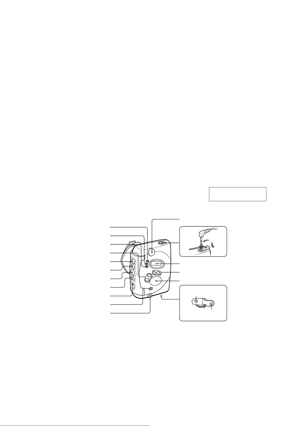
MENU
SET
ENTER
PRESET +/–
M
N
m
Y (FS422ST/FS421 only)
Y (FS422ST/FS421 uniquement)
OFF
HOLD
SECTION 1
GENERAL
VOLUME
i
x
Display
Afficheur
TUNING +, –
FM, AM
Air outlet
Evacuation d’air
This section is extracted
from instruction manual.
Rubber cap
Capuchon en
caoutchouc
Notes on chip component replacement
• Never reuse a disconnected chip component.
• Notice that the minus side of a tantalum capacitor may be
damaged by heat.
Flexible Circuit Board Repairing
• Keep the temperature of soldering iron around 270˚C
during repairing.
• Do not touch the soldering iron on the same conductor of the
circuit board (within 3 times).
• Be careful not to apply force on the conductor when soldering
or unsoldering.
2
WATER PROOF SECTION
)
WM-FS421
SECTION 2
SERVICE NOTE
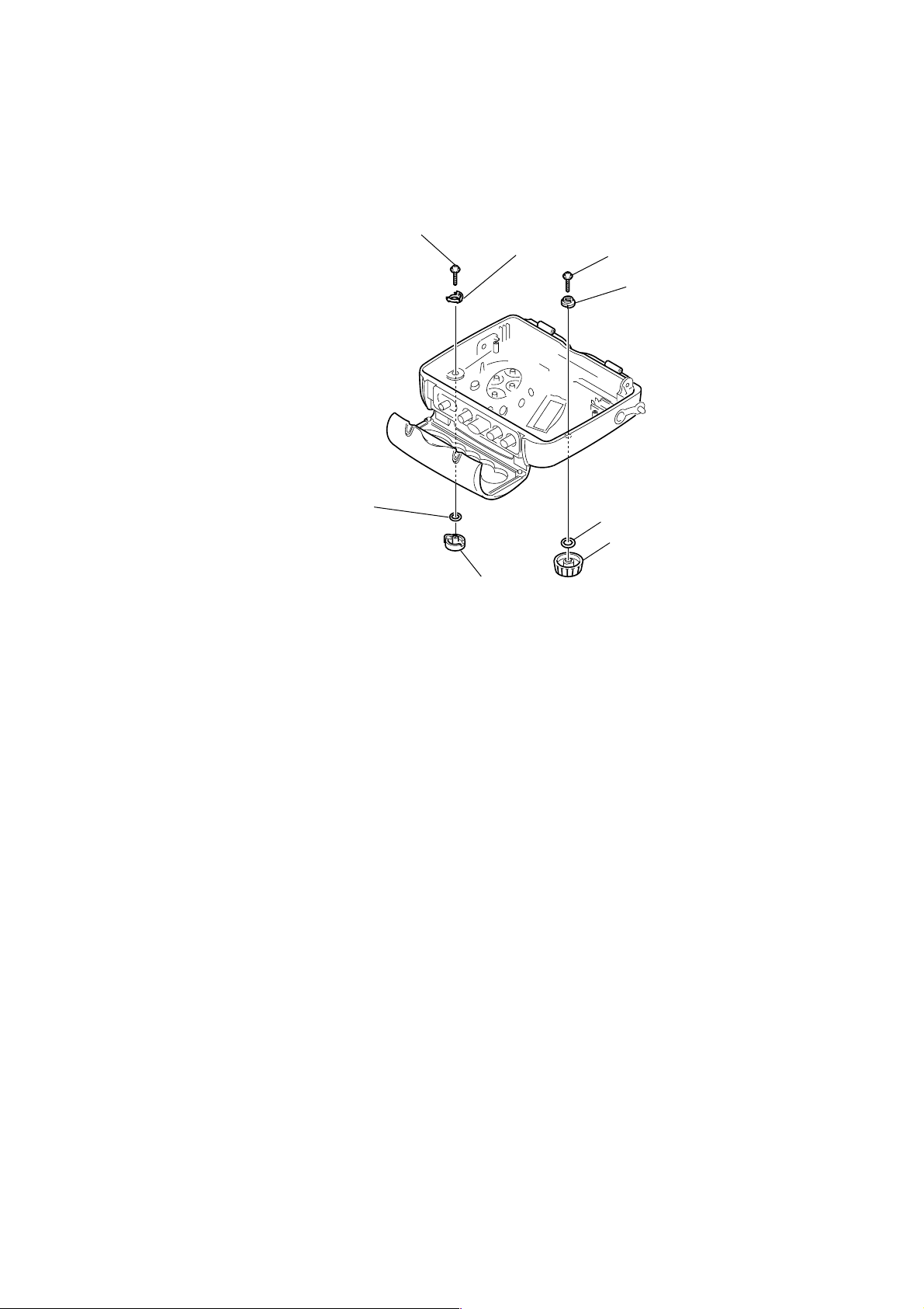
Note : In case the parts in the figure are removed for repair, treat them to protect from water drop following the instructions in the figure
• Sony grease SGL-601 : 7-651-000-10
(spread grease, bond etc.)
O Ring (Dia. 2.5 × Dia. 4.5)
(Apply sony grease: SGL-601)
Tapping screw (B)(1.4 × 4)
Knob (Hold)
Joint (AVLS)
×
Tapping screw (B)(1.4
Joint (VOL)
O Ring
(Apply sony grease: SGL-601
Knob (Vol)
4)
3
WM-FS421
)
DISASSEMBLY
Note : Disassemble the unit in the order as shown below.
SECTION 3
Set
Main Assy
Chassis Sub Assy
MAIN Board and Mechanism Deck
Note : Follow the disassembly procedure in the numerical order given.
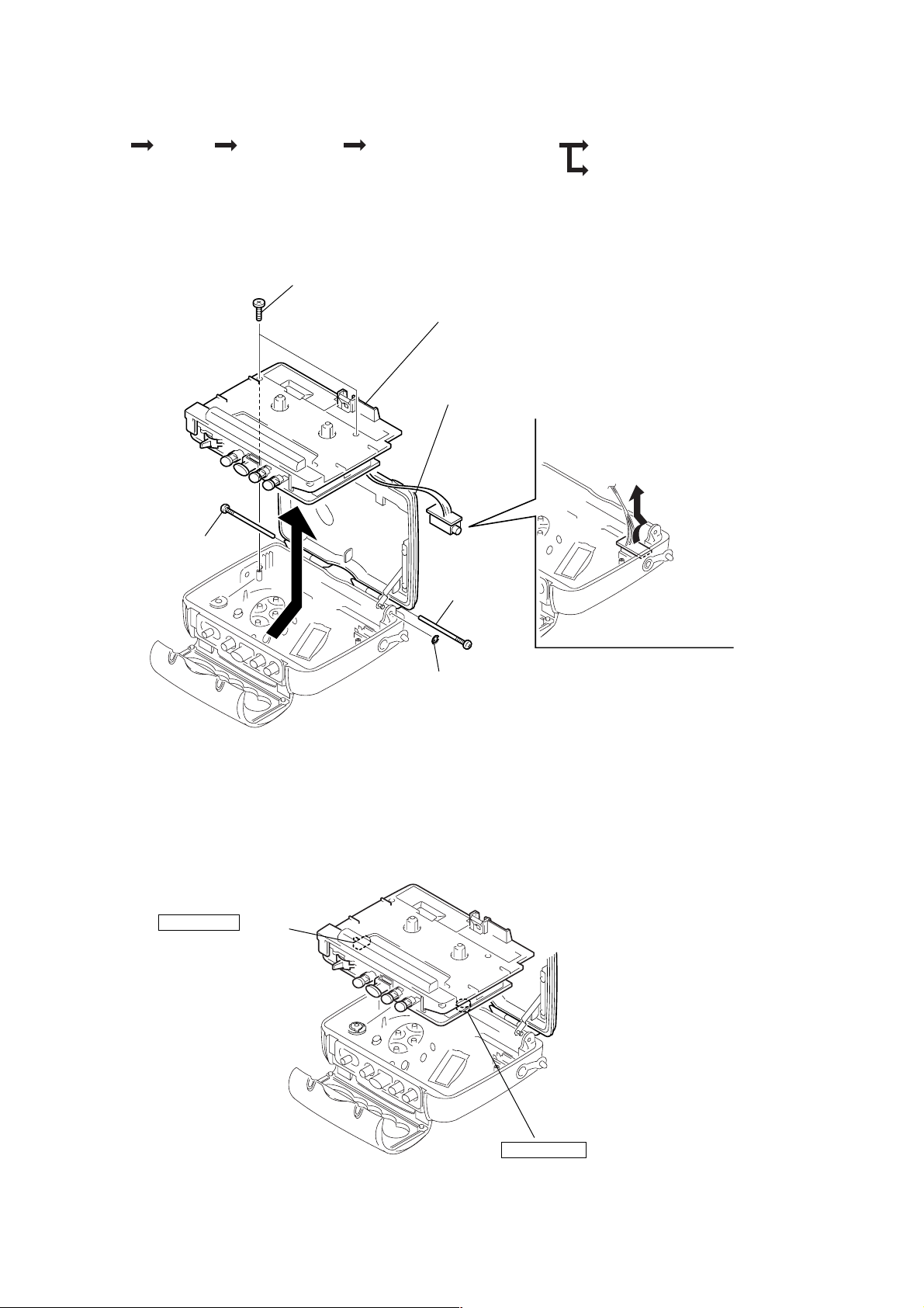
3-1. MAIN ASSY
5
Two screws (+B1.7 × 7)
6
(Be careful not to focibly pull the wire that connects
the main board and the headphone board.)
4
Cassette sub assy, holder
3
Screw, tapping
2
Screw, tapping
Belt
Head, Magnetic (HP701
Remve the main assy in the direction of arrow.
7
Remove the HEADPHONE
borad in the direction of arrow.
1
Stop ring (E 1.2)
CAUTION WHEN ASSEMBLING THE MAIN Assy
• Assemble the main Assy in a way that each switch mates with the corresponding knob each other.
HOLD •
>
(S701)
w
VOLUME
(RV301)
4
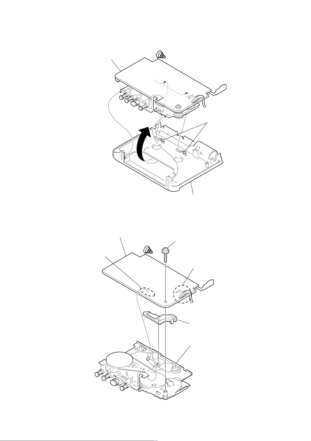
3-2. CHASSIS SUB ASSY
s
)
MAIN board
2
1
T wo claw
WM-FS421
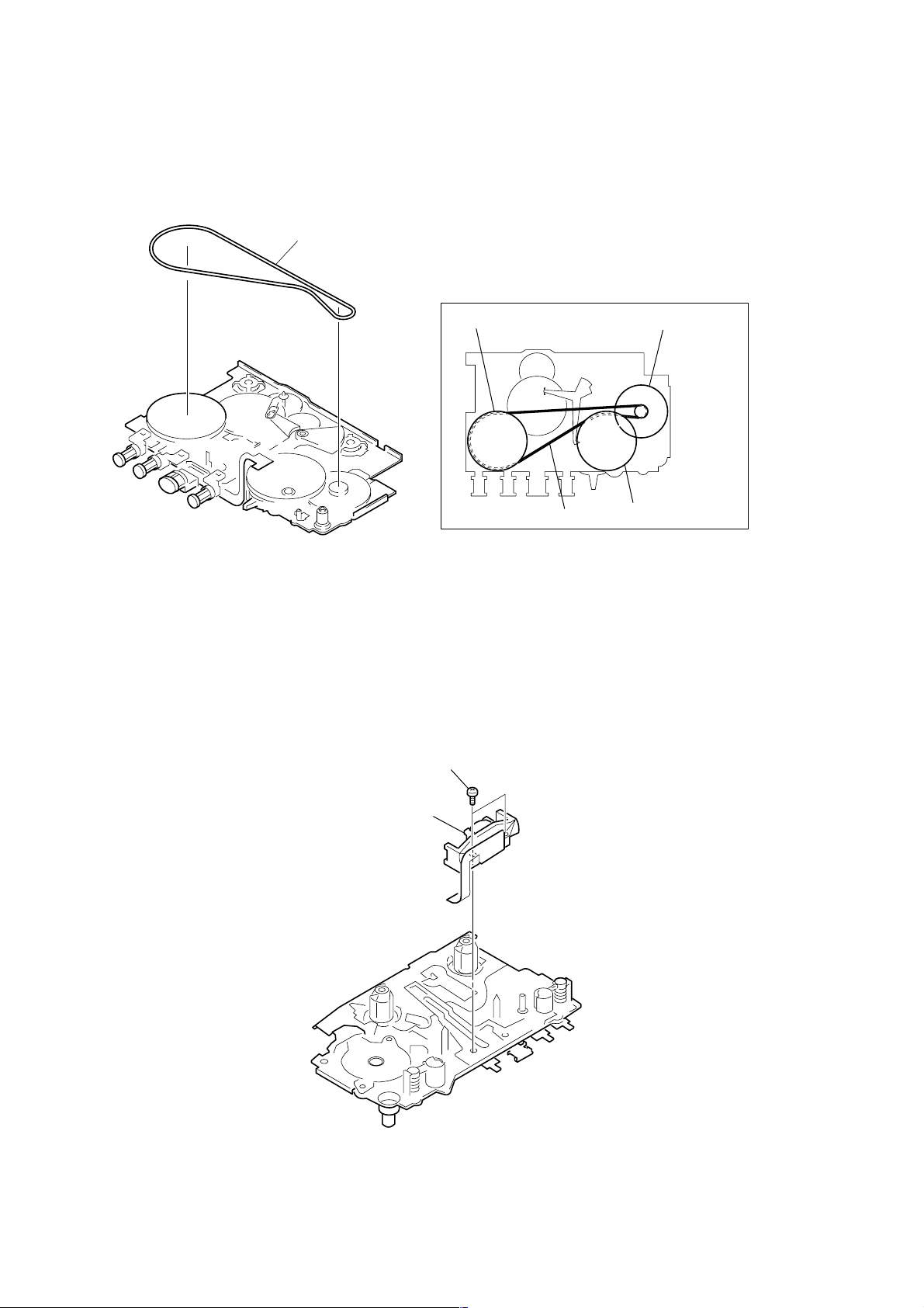
3-3. MAIN BOARD AND MECHANISM DECK
4
MAIN board
2
Remove the solder
Chassis sub assy
3
Screw (M1.4 ) Toothed Lock
1
Remove the solder (four points
5
Stopper (L2)
6
Mechanism deck
5
WM-FS421
3-4. BELT
Belt
Belt threading
3-5. HEAD, MAGNETIC (HP701)
Capstan wheel assy(SP)
1
Two screws (M1.4)
Belt
Reel/Capstan motor
Capstan wheel assy(SP)
2
Head, magnetic (HP701)
6
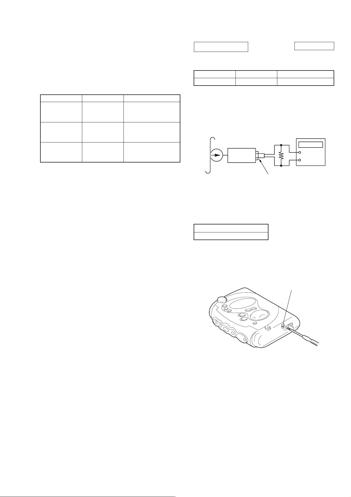
SECTION 4
Test tape
WS-48A
(3 kHz, 0 dB)
Set
J301 (
i
)
16
Ω
digital frequency
counter
+
–
MECHANICAL ADJUSTMENT
WM-FS421
SECTION 5
ELECTRICAL ADJUSTMENT
PRECAUTION
1. Clean the following parts with a denatured-alcohol-moistened
swab:
playback head pinch roller
rubber belts capstan
2. Do not use a magnetized screwdriver for the adjustments.
Torque Measurement
Mode
FWD
FWD
Back T ension
FF, REW
Torque Meter
CQ-102C
CQ-102C
CQ-201B
Meter Reading
2.0 to 4.1 N•m
(20 to 42 g•cm)
(0.27 to 0.58 oz•inch)
More tham 0.20 N•m
(More than 2.0 g•cm)
(More than 0.027 oz•inch)
More tham 4.9 N•m
(More than 50 g•cm)
(More than 0.69 oz•inch)
TAPE SECTION
Test T ape
Tape
WS-48A
Tape Speed Adjustment
Procedure:
Mode: Playback
Adjustment V alue: normal tape speed
Adjust the tape speed adjustment R V601, so that the freqency counter
reading becomes 3,000Hz.
Signal
3 kHz, 0 dB
0 dB = 0.775 V
Used for
Tape speed adjustment
Specification V alue:
Digital frequency counter
2,970 to 3,030 Hz
Frequency difference between the beginning and the end of the tape
should be within 1.5 % (45 Hz).
Adjustment Location:
RV601
7
 Loading...