

Sony WMEX-921 Service manual
WM-EX921
SERVICE MANUAL
Ver 1.0 2001.10
Manufactured under license from Dolby Laboratories.
“Dolby” and the double-D symbol are tr ademarks of
Dolby Laboratories.
SPECIFICATIONS
Frequency response (Dolby NR off)
Playback: 30 - 18 000 Hz
Output
Headphones (i jack)
Load impedance 8 - 300 Ω
Power requirements
1.5 V
One rechargeable battery
Dimensions (w/h/d)
Approx. 77.1 × 108.8 × 20.2 mm
Mass
Approx. 147 g
Supplied accessories
Stereo headphones or earphones with remote control (1)
Battery charging stand (1)
AC power adaptor (1)
Rechargeable battery (NH-14WM (A), 1.2 V, 1 350 mAh
(MIN), Ni-MH) (1)
Rechargeable battery carrying case (1)
Carrying pouch (1)
Design and specifications subject to change without notice.
AEP Model
E Model
Chinese Model
Tourist Model
Model Name Using Similar Mechanism NEW
Tape T ransport Mechanism T ype MT-WMEX921-162
Battery life (Approx. hours) (in playback) (JEITA*)
Rechargeable NH-14WM (A) 45
fully charged
* Measured value by the standard of JEITA (Japan Electronics
and Information Technology Industries Association). (Using a
Sony HF series cassette tape)
Note
• The battery life may be shorter depending on the
operating condition and the surrounding
temperature.
9-873-307-01 Sony Corporation
2001J0500-1 Personal Audio Company
C 2001.10 Published by Sony Engineering Corporation
CASSETTE PLAYER

WM-EX921
TABLE OF CONTENTS
1. SERVICING NOTES ............................................... 3
2. GENERAL ................................................................... 5
3. DISASSEMBLY
3-1. Disassembly Flow ........................................................... 6
3-2. Case Section .................................................................... 6
3-3. MAIN Board ................................................................... 7
3-4. Belt (F0) .......................................................................... 7
3-5. Motor, DC (Capstan/Reel) (M601)................................. 8
3-6. Lid Assy, Cassette ........................................................... 8
3-7. Ornament (Open) Block Assy......................................... 9
3-8. Holder (FA) Assy ............................................................ 9
3-9. “Lever (N2) Assy, Pinch”, “Lever (R2) Assy, Pinch”.... 10
3-10. Head, Magnetic (Playback) (HP901) ............................. 10
4. MECHANICAL ADJUSTMENTS....................... 11
5. ELECTRICAL ADJUSTMENTS......................... 11
6. DIAGRAMS
6-1. Block Diagram ................................................................ 13
6-2. Note for Printed Wiring Board
and Schematic Diagrams ................................................ 14
6-3. Printed Wiring Board
– MAIN Board (Component Side) – .............................. 16
6-4. Printed Wiring Board
– MAIN Board (Conductor Side) – ................................ 17
6-5. Schematic Diagram – MAIN Board (1/2) – .................. 18
6-6. Schematic Diagram – MAIN Board (2/2) – .................. 19
6-7. IC Pin Function Description ........................................... 20
7. EXPLODED VIEWS
7-1. Cassette Lid Assy Section............................................... 21
7-2. Case Section .................................................................... 22
7-3. MAIN Board Section ...................................................... 23
7-4. Mechanism Deck Section-1 (MT-WMEX921-162) ....... 24
7-5. Mechanism Deck Section-2 (MT-WMEX921-162) ....... 25
7-6. Mechanism Deck Section-3 (MT-WMEX921-162) ....... 26
8. ELECTRICAL PARTS LIST ............................... 27
Note on the AC power adaptor
Use only the supplied AC power adaptor. Do not use
any other AC power adaptor.
Polarity of
the plug
Notes on chip component replacement
• Never reuse a disconnected chip component.
• Notice that the minus side of a tantalum capacitor may be damaged by heat.
Flexible Circuit Board Repairing
• Keep the temperature of the soldering iron around 270 ˚C during repairing.
• Do not touch the soldering iron on the same conductor of the
circuit board (within 3 times).
• Be careful not to apply force on the conductor when soldering
or unsoldering.
UNLEADED SOLDER
Boards requiring use of unleaded solder are printed with the leadfree mark (LF) indicating the solder contains no lead.
(Caution: Some printed circuit boards may not come printed with
the lead free mark due to their particular size)
: LEAD FREE MARK
Unleaded solder has the following characteristics.
• Unleaded solder melts at a temperature about 40 ˚C higher than
ordinary solder.
Ordinary soldering irons can be used but the iron tip has to be
applied to the solder joint for a slightly longer time.
Soldering irons using a temperature regulator should be set to
about 350 ˚C .
Caution: The printed pattern (copper foil) may peel away if the
heated tip is applied for too long, so be careful!
• Strong viscosity
Unleaded solder is more viscous (sticky , less prone to flow) than
ordinary solder so use caution not to let solder bridges occur
such as on IC pins, etc.
• Usable with ordinary solder
It is best to use only unleaded solder but unleaded solder may
also be added to ordinary solder.
SAFETY-RELATED COMPONENT WARNING!!
COMPONENTS IDENTIFIED BY MARK 0 OR DOTTED
LINE WITH MARK 0 ON THE SCHEMA TIC DIAGRAMS
AND IN THE PARTS LIST ARE CRITICAL TO SAFE
OPERATION. REPLACE THESE COMPONENTS WITH
SONY PARTS WHOSE PART NUMBERS APPEAR AS
SHOWN IN THIS MANUAL OR IN SUPPLEMENTS PUBLISHED BY SONY.
2
SECTION 1
SERVICING NOTES
WM-EX921
This set detects the rotation of the idler gear (A) (side S) using the
photo reflector (PH701). The PH701 is mounted on the MAIN
board, therefore the idler gear (A) (side S) cannot be detected with
the MAIN board removed. As a result, the motor (M601) cannot
be controlled, causing malfunction.
Further, the DIRECTION switch (S702) is also mounted on the
MAIN board, and with the board removed, the mechanism position cannot be detected and the operation is not changed over.
Therefor, when the voltage check is e xecuted with the MAIN board
removed, follow the procedure provided below.
1. Setting
1) Refer to “3. DISASSEMBLY”, and remove the MAIN board.
2) Connect the MAIN board to the motor (M601) and the plunger
(PM701) using jumper wires. These can be connected easily
with the use of the extension tool (Part No. 1-769-143-11) (ten
in one set).
3) Short the lands (BP1) by solder.
4) Connect the AF oscillator to the TP31 (PH-S) and the TP10
(GND).
5) Supply 1.3 V to the battery terminals using the regulated po wer
supply.
2. Preset state
T o set the PLAY, FF , REW modes, the preset state must be set.
1) Check that the slider (NRA) and the DIRECTION switch
(S702) are set to the center position. If not, set the preset state
as follow.
2) Move the DIRECTION switch (S702) to the side, which the
slider (NRA) is facing.
3) The slider (NRA) will move when the regulated po wer supply
switch is set to OFF once and then set to ON. Move the DIRECTION switch (S702) according to this timing and set to
the center position.
3. FF, REW modes
1) Check that the preset state is set.
2) Input the square wave or sine wave to the TP31 (PH-S) and
the TP10 (GND).
3) Move the jog lever (S703) toward [FF] or [REW].
4. PLAY mode
1) Check that the preset state is set.
2) Input the square wave or sine wave to the TP31 (PH-S) and
the TP10 (GND).
3) Press the jog lever (S703) will move the slider (NRA) once
towards the side REV and then to the side FWD. Move the
DIRECTION switch (S702) according to this timing will set
the PLA Y mode (side FWD). Pr ess the jog lever (S703) another
time for a second and move the DIRECTION switch (S702)
according to the movement of the slider (NRA) will set the
PLAY mode (side REV).
Note 1: If the above fails, perform from preset again.
Note 2: When using headphones, the timing for move the DIRECTION
switch (S702) can be determined from the beep sound.
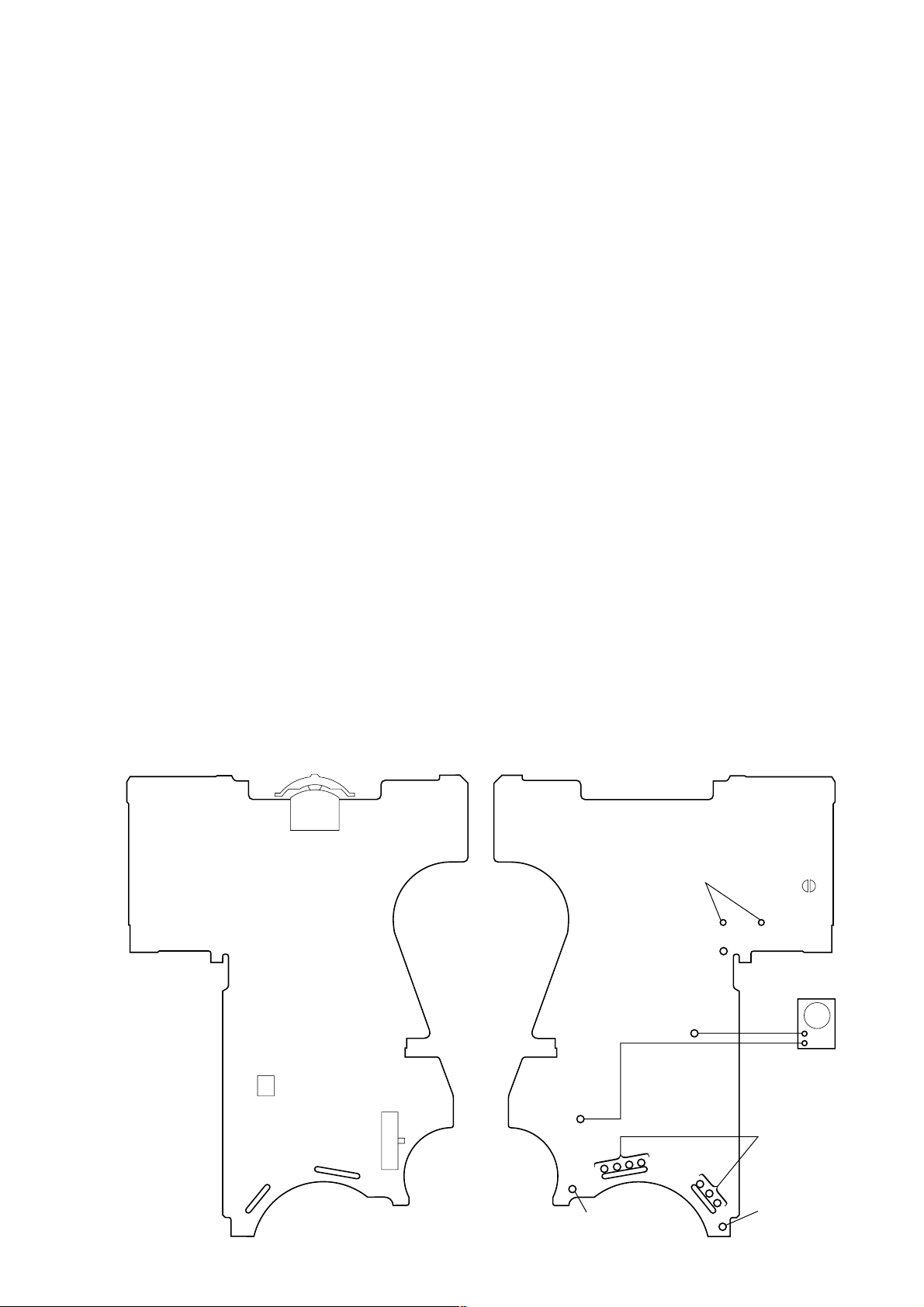
– MAIN Board (Component Side) – – MAIN Board (Conductor Side) –
PUSH – Y/
>
FF
S703
jog lever
PH701
x
r
.
REW
S702
(DIRECTION)
FWD
R
STOP
r
REV
connect to the
plunger (PM701)
battery terminal
TP31 (PH-S)
TP10 (GND)
BP
#
AF oscillator
+
–
square wave
(sine wave)
100 Hz, –3.5 dB
connect to the
motor (M601)
battery terminal
battery
terminal
#
3
3
WM-EX921
y
y
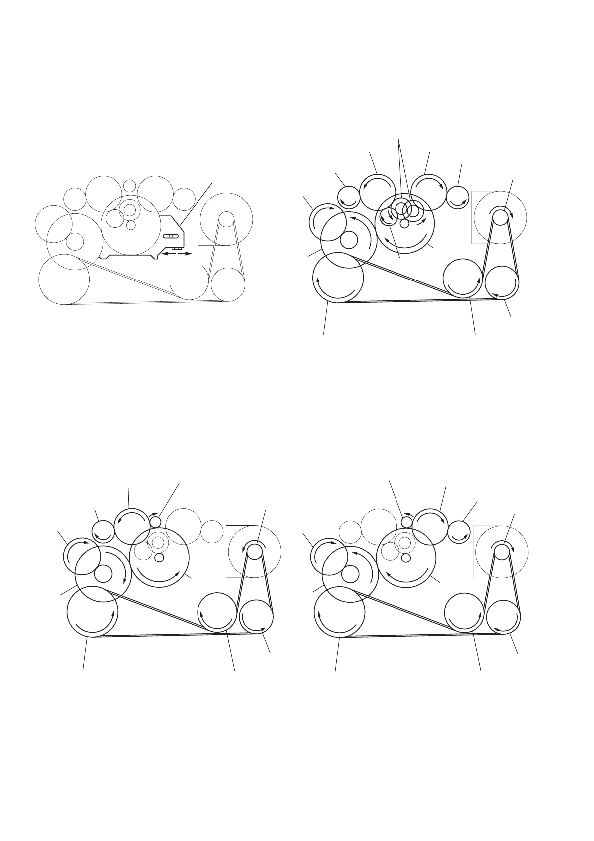
Slider (NRA) Rotation system
Rotation system during PLAY.
idler gear (A) (side T)
gear (REEL) (side T)
slider (NRA)
cam gear
gear (NR)
(FWD : left side/
REV : right side)
idler gear (A) (side S)
gear (REEL) (side S)
motor pulley
side F
side R
center
gear (Y)
insert flywheel (N) insert flywheel (R)
idler gear (B)
Rotation system during FF. Rotation system during REW.
gear (FR)
(REW: right side)
idler gear (A) (side T)
gear (REEL) (side T)
cam gear
gear (FR)
(FF: left side)
motor pulley
cam gear
clutch assy (F)
idler gear (A)
(side S)
reverse pulley
gear (REEL)
(side S)
motor pulle
clutch assy (F)
gear (Y)
insert flywheel (N) insert flywheel (R)
4
gear (Y)
reverse pulle
clutch assy (F)
reverse pulley
insert flywheel (N) insert flywheel (R)
SECTION 2
GENERAL
WM-EX921
This section is extracted from
instruction manual.
A
B
C
D
Jog lever
Levier Jog
Jog-Hebel
Hold shutter
Cache de
verrouillage
Schutzschieber
Hold shutter
Cache de
verrouillage
Schutzschieber
REV
FWD
Plug in firmly.
Branchez fermement.
Fest einstecken.
FF (+)
HOLD
Jog lever
Levier Jog
Jog-Hebel
REW
HOLD
CHARGE
Y•x
FF
REW (–)
SOUND
MODE
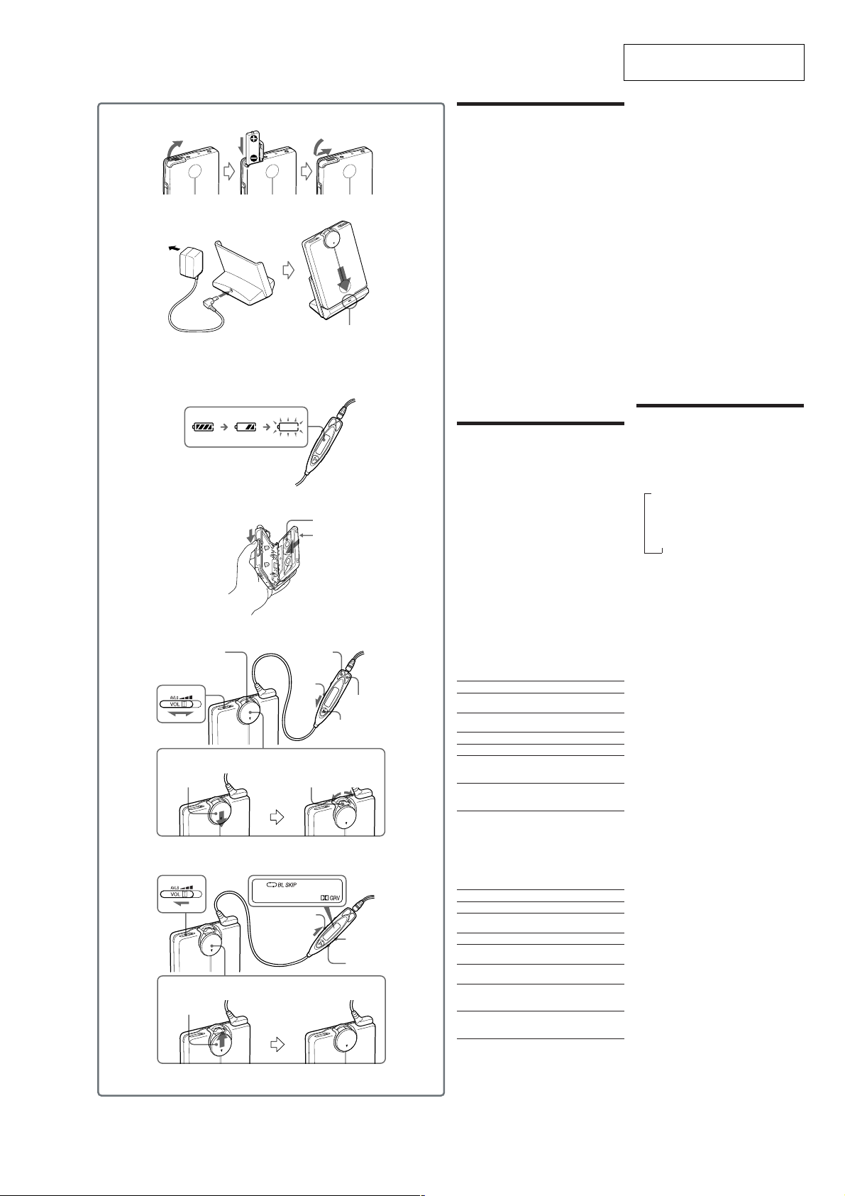
Preparations
Rechargeable Battery
1Insert the supplied rechargeable battery NH-14WM
(A) into the rechargeable battery compartment with
correct polarity.
2Connect the supplied AC power adaptor to the
charging stand, plug in the AC power adaptor to
the house current (mains).
3Place the main unit on the charging stand.
The CHARGE lamp will light up.
About 30 minutes of charging will charge the
battery to last about 3 hours.
Full charging takes about 6 hours.
The CHARGE lamp will go off when charging is
complete.
You can charge the battery about 300 times.
Note
• Do not use the unit while charging. Remove the unit
from the charging stand when using it.
– If you operate the unit while charging, the battery
will not be charged.
– If you operate the unit while charging, it may cause
malfunction.
– Do not place the unit on the charging stand without
the rechargeable battery. Otherwise, it may cause
malfunction.
When to charge the battery
Charge the battery when “e” flashes in the display.
Note
• After the battery is replaced, the setting of the SOUND
and MODE buttons will be erased.
Playing a Tape
1 Insert a cassette and if the HOLD function of
the remote control is on, slide the HOLD
switch in the opposite direction of the arrow
to unlock the controls.
2 Press Y(play)•x(stop) on the remote
control* and adjust the volume with VOL.
Notes on volume control
• The VOL switch on the main unit** has three steps.
Generally, set it to the center and make fine volume
adjustments on the remote control. Set it to the
maximum when the recording level is low. If set to
AVLS (minimum), AVLS is activated (see “Protecting
Your Hearing —AVLS”).
• The sound cannot be turned down all the way.
* The Y•x button on the remote control has a tactile
dot.
** There is a tactile dot beside the VOL switch on the
main unit to show the direction to turn up the
volume.
Note on the cassette holder
When opening the cassette holder, make sure the tape is
stopped, then slide the OPEN switch.
If the cassette holder is opened when the tape is running,
the tape may loosen and be damaged.
To
Switch playback to
the other side
Stop playback
Fast forward*
Rewind*
Play the other side from
the beginning (Skip
Reverse function)
Play the same side from
the beginning (Rewind
Auto Play function)
* If
Y•x
on the remote control is pressed during fast
forward or rewind, the Walkman switches to playback.
Operation on the main unit
You can operate the tape with the jog lever on the
main unit. If the jog lever is hidden (i.e., on hold),
slide hold shutter in the direction of “V” to release
hold.
To
Play back
Switch playback to
the other side
Stop playback
Fast forward*
Rewind*
Play the other side from
the beginning (Skip
Reverse function)
Play the same side from
the beginning (Rewind
Auto Play function)
* If the jog lever on the main unit is pressed during fast
forward or rewind, the Walkman switches to playback.
A
B
C
Press
Y•x for more than a
second during playback
Y•x once during
playback
FF during stop
REW during stop
FF for 2 seconds or more
during stop
REW for 2 seconds or more
during stop
Jog lever
Press once.
Press for more than a
second during playback.
Press once.
Move toward .FF once
during stop.
Move toward >REW
once during stop.
Move and hold toward
.FF for 2 seconds or
more during stop.
Move and hold toward
>REW for 2 seconds or
more during stop.
Other Tape Operations
To play the next track/succeeding 9 tracks
from the beginning (AMS*)
On the remote control: Press FF once/repeatedly
during playback.
On the main unit: Move the jog lever toward .FF
once/repeatedly during playback.
To play the current track/previous 8 tracks
from the beginning (AMS*)
On the remote control: Press REW once/repeatedly
during playback.
On the main unit: Move the jog lever toward
>REW once/repeatedly during playback.
* Automatic Music Sensor
Repeating the current track (repeat single
track function)
On the remote control: Press Y•x twice during
playback (“REP” lights up).
On the main unit: Press the jog lever twice during
playback.
To stop a single repeat
Press Y•x or the jog lever once.
Fast forward/rewind while listening to the
sound (CUE/REVIEW)
On the remote control: Press and hold FF/REW
during playback and release it at the point you want.
On the main unit: Move and hold the jog lever
toward .FF/>REW during playback and
release it at the point you want.
Using Other Functions
Adjusting Playback Mode
You can adjust the playback direction mode (s or
d) as well as the BL SKIP mode (on or off).
1Press MODE repeatedly. With each press the
indications change as follows:
B
s
v
s BL SKIP
v
d
v
d BL SKIP
•When “BL SKIP” is displayed, the tape is fastforwarded to the next track if there is a blank space
of longer than 12 seconds. You will hear repeated
sets of three short beeps when skipping a blank.
•When “s” is displayed, both sides of the tape is
played repeatedly.
•When “d” is displayed, both sides of the tape is
played once (if you start from R (REV) side, only
REV side will be played).
Note
• You cannot adjust the playback mode during fastforward or rewind.
Playing a Tape Recorded with the
Dolby* B NR System
Hold down SOUND until “;” appears in the
display.
To cancel Dolby B NR, hold down SOUND again
until “;” disappears.
Note
• You cannot turn on/off the Dolby B NR function
during fast-forward or rewind.
Emphasizing Sound
1Press SOUND repeatedly. With each press, the
indications change as follows:
RV (Sound Revitalizer): emphasizes treble sound
MB (Mega Bass): emphasizes bass sound
(moderate effect)
GRV (Groove): emphasizes bass sound (strong
effect)
none: normal (no effect)
Notes
• If the sound is distorted with the mode “GRV”, turn
down the volume of the main unit or select other
modes.
• You cannot change the mode during fast-forward or
rewind.
Protecting Your Hearing — AVLS
(Automatic Volume Limiter System)
D
1Set the VOL switch on the main unit to AVLS.
To cancel the AVLS function
Set the VOL switch of the main unit to the center or
maximum.
Locking the Controls — HOLD
D
Function
On the remote control, slide the HOLD switch in the
direction of the arrow to lock the controls.
On the main unit, close the hold shutter so that the
jog lever becomes hidden.
D
D
D
5
WM-EX921
• This set can be disassembled in the order shown below.
3-1. DISASSEMBLY FLOW
SECTION 3
DISASSEMBLY
Set 3-2. Case Section 3-3. Main Board
3-7. Ornament (Open) Block Assy3-6. Lid Assy, Cassette
3-9. “Lever (N2) Assy, Pinch”, “Lever (R2) Assy, Pinch”
Note: Follow the disassembly procedure in the numerical order given.
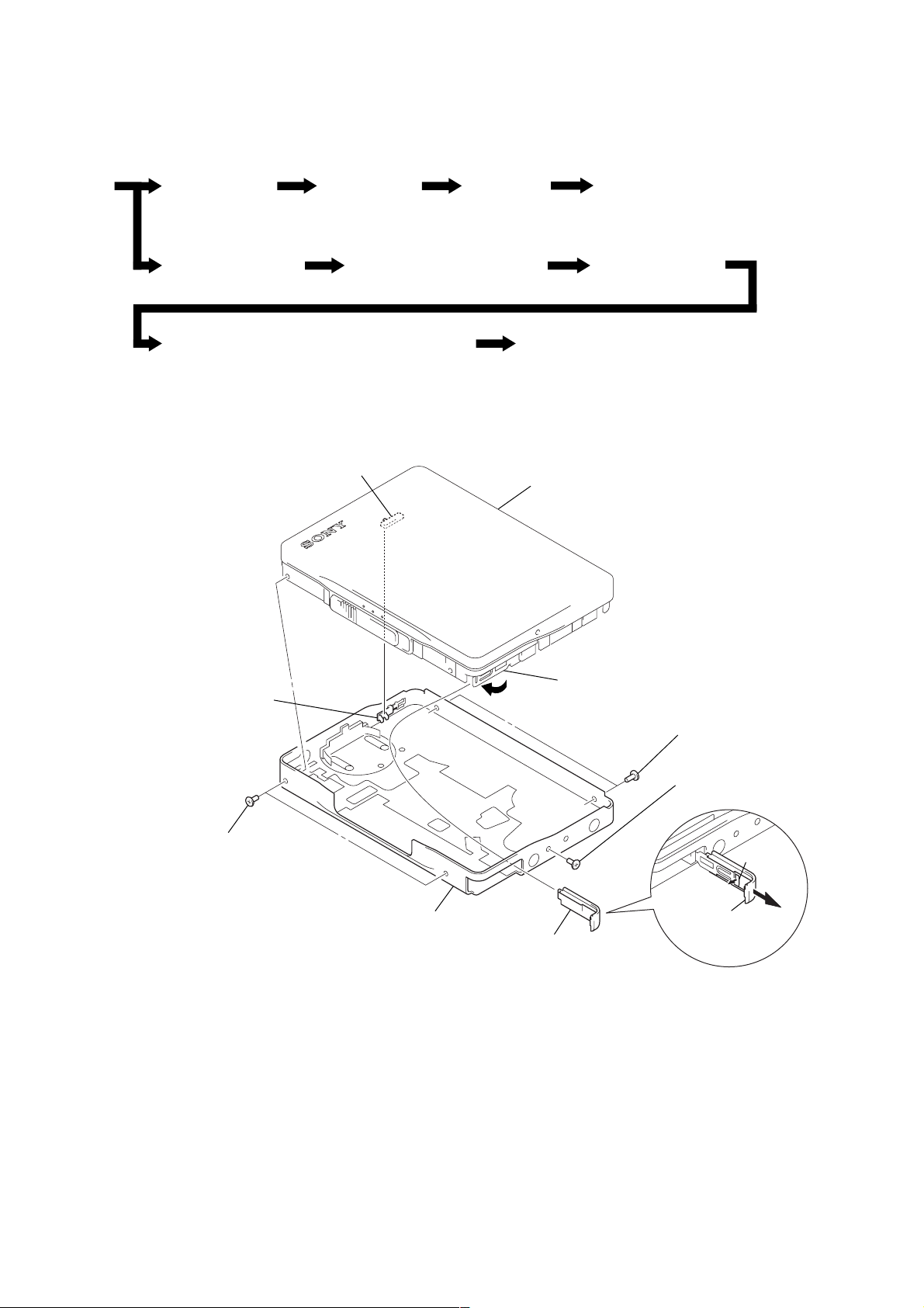
3-2. CASE SECTION
S301
Note: On installation
“lid assy, cassette” adjust
the S301 and knob (vol).
3-4. Belt (F0) 3-5. Motor, DC (Capstan/Reel) (M601)
3-8. Holder (FA) Assy
3-10. Head, Magnetic (Playback) (HP901)
cassette assy, lid
knob (VOL)
5
two screws
(M1.4)
7
case section
4
Close terminal board assy.
3
lid, battery case
5
two screws
(M1.4)
6
screw (M1.4)
2
1
Open “lid, battery
case”.
claw
6
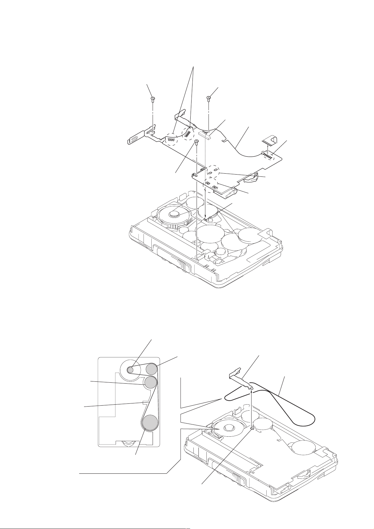
3-3. MAIN BOARD
2
screw
2
screw
1
Remove seven solders of “motor, DC (M601)”.
2
screw (M1.4) (toothed lock)
S702
3
MAIN board
1
1
Remove four solders of
slider
“switch, leaf (S704)”.
WM-EX921
1
Remove six solders of
head flexible board.
Remove two solders of
“solenoid, plunger”.
Note: On installation
MAIN board adjust
the S702 and slider.
3-4. BELT (F0)
flywheel (R),
insert
belt (F0)
pulley, motor
pulley, reverse
2
terminal board, battery
3
belt (F0)
flywheel (N), insert
1
Remove solder of
“terminal board, battery”.
7
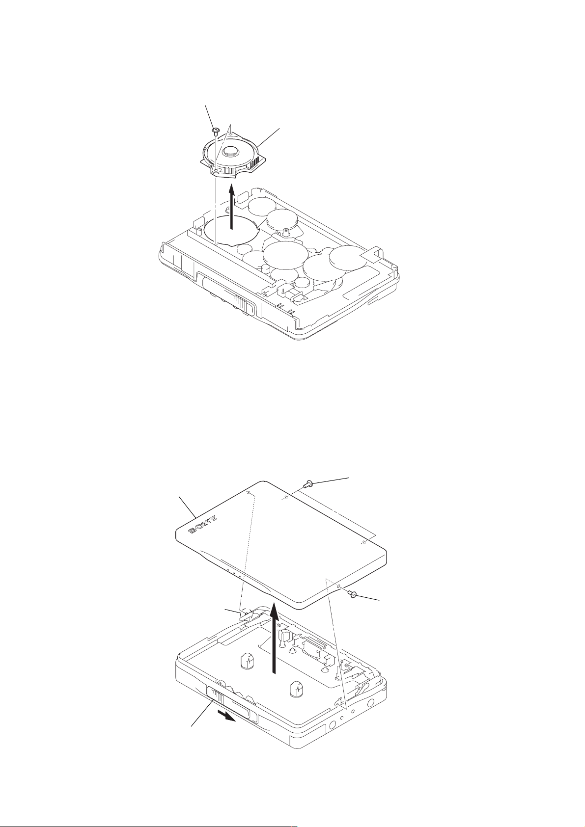
WM-EX921
)
3-5. MOTOR, DC (CAPSTAN/REEL) (M601)
1
two screws (M1.4)
2
motor, DC (capstan/reel) (M601
3-6. LID ASSY, CASSETTE
4
lid assy, cassette
3
boss
2
two screws
(M1.4)
2
screw (M1.4)
1
Open “lid assy, cassette”.
8
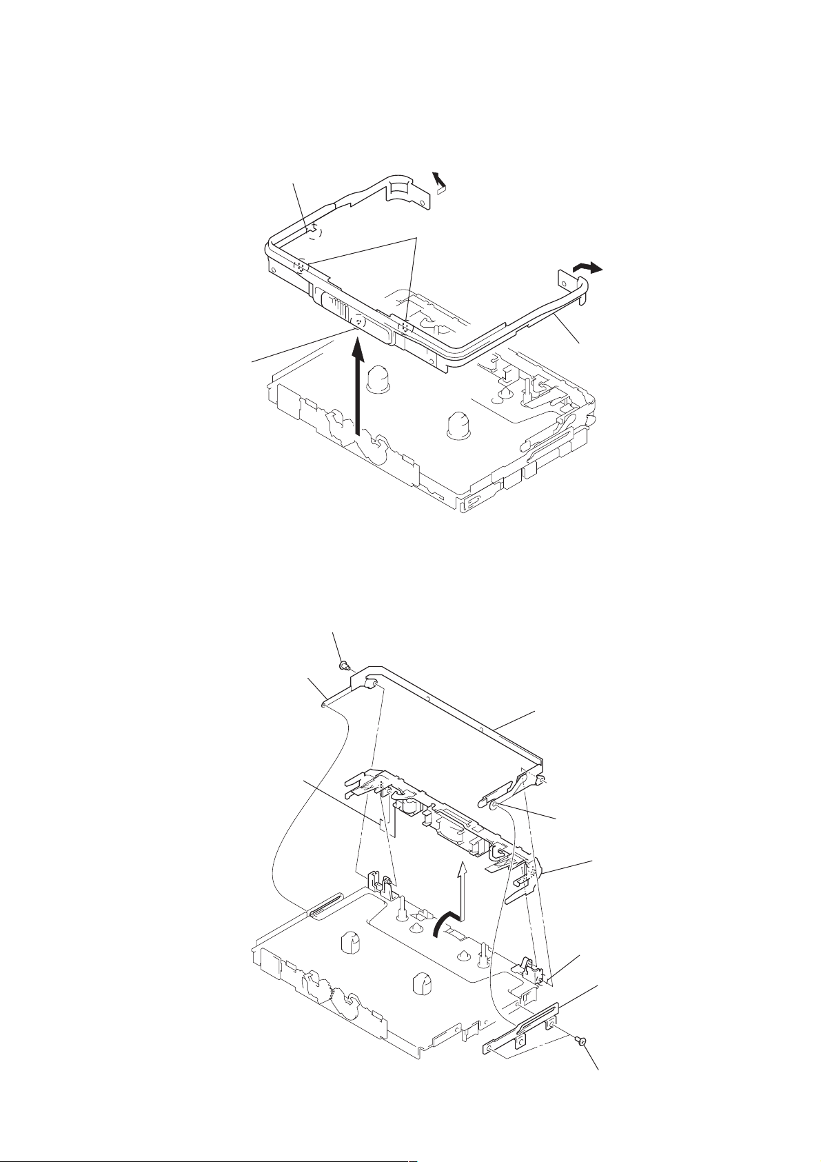
3-7. ORNAMENT (OPEN) BLOCK ASSY
k
WM-EX921
3
boss
2
claw
4
two claws
1
1
5
ornament (open) block assy
3-8. HOLDER (FA) ASSY
5
lever (S) (/M), lock
8
Remove six solders of
head flexible board.
4
screws (M1.4)
7
bracket (cassette/910) assy
2
boss
9
holder (FA) assy
6
boss
3
lever (B) (/M), loc
1
two screws (M1.4)
9
 Loading...