

Sony WMEX-910 Service manual
WM-EX910
SERVICE MANUAL
Ver 1.1 2001.01
Photo: Blue model
Manufactured under license from Dolby Laboratories.
“Dolby” and the double-D symbol are tr ademarks of
Dolby Laboratories.
SPECIFICATIONS
Frequency response (Dolby NR off)
Playback: 30 - 18 000 Hz
Output
Headphones (i jack)
Load impedance 8 - 300 Ω
Power requirements
1.5 V
One rechargeable battery
One R6 (size AA) battery
Dimensions (w/h/d)
Approx. 76.3 × 108.4 × 17.6 mm
1
3
(3
⁄
× 4
⁄8 x 23⁄
8
Mass
Approx. 140 g (5.0 oz.)
Supplied accessories
Battery case (1)
Stereo headphones or earphones with
remote control (1)
Battery charger (1)
Rechargeable battery (NC-6WM, 1.2V,
600 mAh, Ni-Cd) (1)
Rechargeable battery carrying case (1)
Carrying pouch (1)
inches)
32
AEP Model
E Model
Chinese Model
Tourist Model
Model Name Using Similar Mechanism NEW
Tape Transport Mechanism T ype MT-WMEX910-162
Battery life (Approx. hours)
(in playback) (EIAJ*)
Rechargeable NC-6WM 20
fully charged
Sony alkaline LR6 (SG)** 66
Rechargeable NC-6WM 84
Sony alkaline LR6 (SG)
used together
* Measured value by the standard
of EIAJ (Electronic Industries
Association of Japan). (Using a
Sony HF series cassette tape)
**When using a Sony LR6 (SG)
“STAMINA” alkaline dry battery
(produced in Japan).
Design and specifications subject to
change without notice.
9-873-015-12 Sony Corporation
2001A0500-1 Audio Entertainment Group
C 2001.1 General Engineering Dept.
CASSETTE PLAYER

WM-EX910
TABLE OF CONTENTS
1. SERVICING NOTES ............................................... 3
2. GENERAL ................................................................... 5
3. DISASSEMBLY ......................................................... 6
4. MECHANICAL ADJUSTMENTS....................... 11
5. ELECTRICAL ADJUSTMENTS......................... 11
6. DIAGRAMS
6-1. Block Diagram ................................................................ 13
6-2. Printed Wiring Board ...................................................... 14
6-3. Schematic Diagram ......................................................... 15
6-4. IC Pin Function Description ........................................... 16
7. EXPLODED VIEWS ................................................ 18
8. ELECTRICAL PARTS LIST ............................... 21
Notes on chip component replacement
• Never reuse a disconnected chip component.
• Notice that the minus side of a tantalum capacitor may be damaged by heat.
Flexible Circuit Board Repairing
• Keep the temperature of the soldering iron around 270 ˚C during repairing.
• Do not touch the soldering iron on the same conductor of the
circuit board (within 3 times).
• Be careful not to apply force on the conductor when soldering
or unsoldering.
SAFETY-RELATED COMPONENT WARNING!!
COMPONENTS IDENTIFIED BY MARK 0 OR DOTTED
LINE WITH MARK 0 ON THE SCHEMATIC DIA GRAMS
AND IN THE PARTS LIST ARE CRITICAL TO SAFE
OPERATION. REPLACE THESE COMPONENTS WITH
SONY PARTS WHOSE PART NUMBERS APPEAR AS
SHOWN IN THIS MANUAL OR IN SUPPLEMENTS PUBLISHED BY SONY.
2
SECTION 1
SERVICING NOTES
WM-EX910
This set detects the rotation of the idler gear (A) (side S and side
T) using the photo reflector (PH701, 702). The PH701, 702 are
mounted on the MAIN board, therefore the idler gear (A) (side S
and side T) cannot be detected with the MAIN board removed. As
a result, the motor (M601) cannot be controlled, causing malfunction.
Further, the DIRECTION switch (S702) is also mounted on the
MAIN board, and with the board removed, the mechanism position cannot be detected and the operation is not changed over.
Therefor, when the voltage check is e xecuted with the MAIN board
removed, follow the procedure provided below.
1. Setting
1) Refer to “3. DISASSEMBLY”, and remove the MAIN board.
2) Connect the MAIN board to the motor (M601) and the plunger
(PM701) using jumper wires. These can be connected easily
with the use of the extension tool (Part No. 1-769-143-11) (ten
in one set).
3) Short the lands by solder.
4) Connect the AF oscillator to the TP31 (PH-S), TP32 (PH-T)
and the TP (GND).
5) Supply 1.3 V to the battery terminals using the regulated po wer
supply.
2. Preset state
T o set the PLAY , FF, REW modes, the preset state must be set.
1) Check that the slider (NR) and the DIRECTION switch (S702)
are set to the center position. If not, set the preset state as follow.
2) Move the DIRECTION switch (S702) to the side, which the
slider (NR) is facing.
3) The slider (NR) will move when the regulated power supply
switch is set to OFF once and then set to ON. Move the DIRECTION switch (S702) according to this timing and set to
the center position.
3. FF, REW modes
1) Check that the preset state is set.
2) Input the square wave or sine wav e to the TP31 (PH-S), TP32
(PH-T) and the TP (GND).
3) Move the jog lever (S703) toward [FF] or [REW].
4. PLAY mode
1) Check that the preset state is set.
2) Input the square wave or sine wav e to the TP31 (PH-S), TP32
(PH-T) and the TP (GND).
3) Press the jog lever (S703) will move the slider (NR) once towards the side REV and then to the side FWD. Move the DIRECTION switch (S702) according to this timing will set the
PLA Y mode (side FWD). Press the jog lever (S703) another time
for a second and move the DIRECTION switch (S702) according to the movement of the slider (NR) will set the PLAY
mode (side REV).
Note 1: If the above fails, perform from preset again.
Note 2: When using headphones, the timing for move the DIRECTION
switch (S702) can be determined from the beep sound.
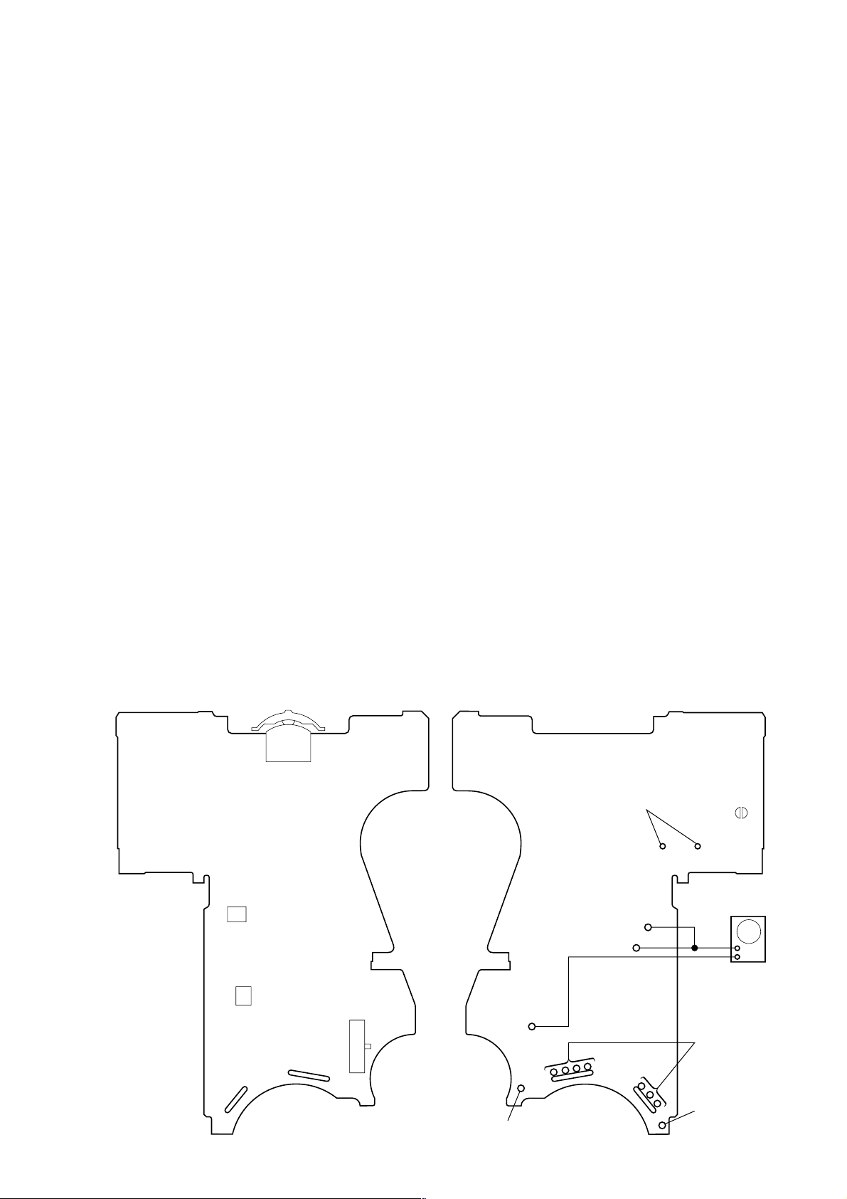
– MAIN BOARD
(Side A) –
PUSH – Y/
>
REW
PH702
PH701
r
.
S703
jog lever
S702
(DIRECTION)
FF
x
– MAIN BOARD (Side B) –
connect to the
FWD
R
STOP
r
REV
plunger (PM701)
TP32 (PH-T)
TP31 (PH-S)
TP (GND)
BP701
AF oscillator
+
–
square wave
(sine wave)
100 Hz, –3.5 dB
connect to the
motor (M601)
battery terminal
battery
terminal
#
3
3
WM-EX910
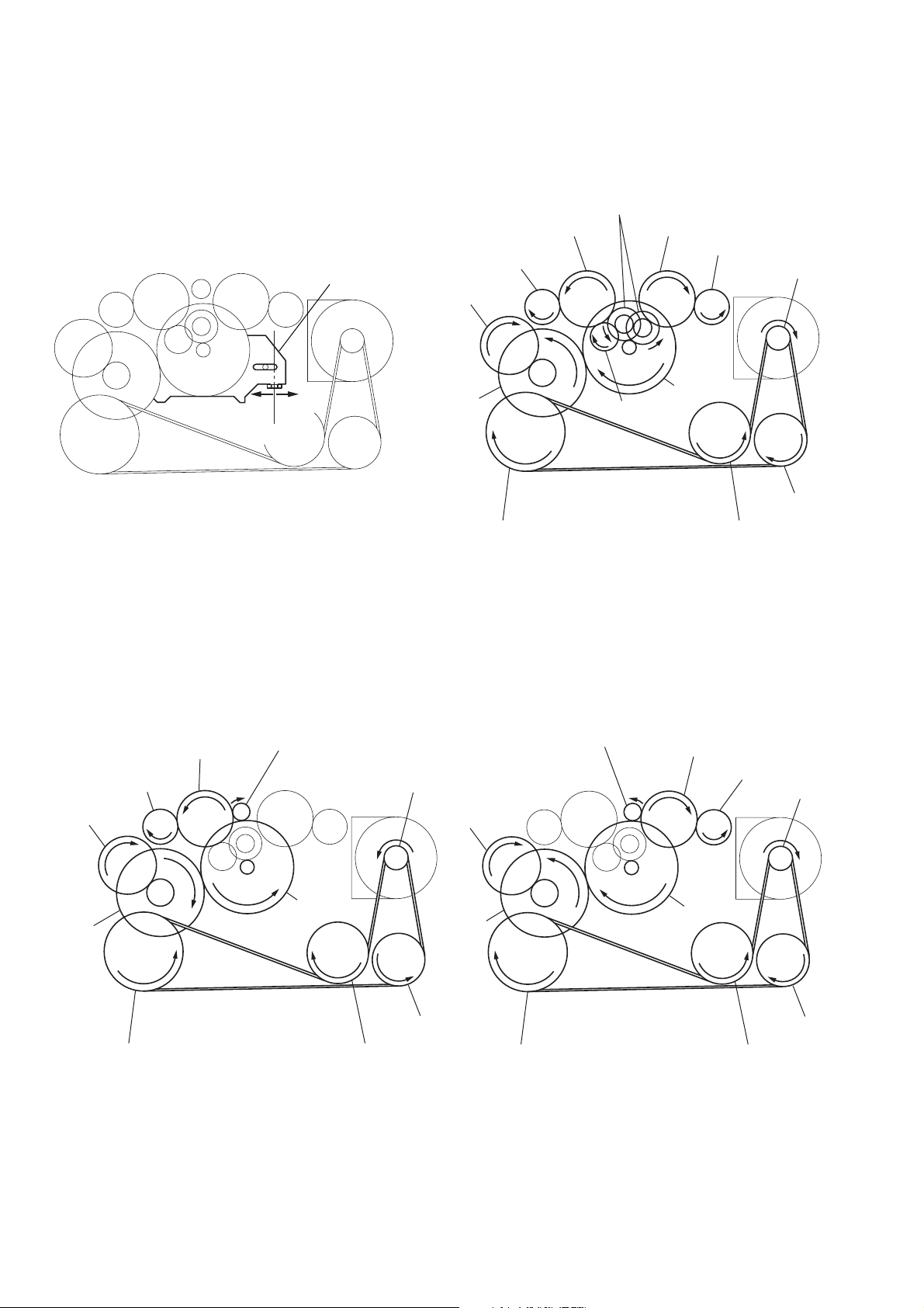
y
y
Slider (NR) Rotation system
Rotation system during PLAY.
idler gear (A) (side T)
gear (REEL) (side T)
slider (NR)
cam gear
gear (NR)
(FWD : left side/
REV : right side)
idler gear (A) (side S)
gear (REEL) (side S)
motor pulley
side F
side R
center
gear (Y)
insert flywheel (N) insert flywheel (R)
idler gear (B)
Rotation system during FF. Rotation system during REW.
gear (FR)
(REW: right side)
idler gear (A) (side T)
gear (REEL) (side T)
cam gear
gear (FR)
(FF: left side)
motor pulley
cam gear
clutch assy (F)
idler gear (A)
(side S)
reverse pulley
gear (REEL)
(side S)
motor pulle
clutch assy (F)
gear (Y)
insert flywheel (N) insert flywheel (R)
4
gear (Y)
reverse pulle
clutch assy (F)
reverse pulley
insert flywheel (N) insert flywheel (R)
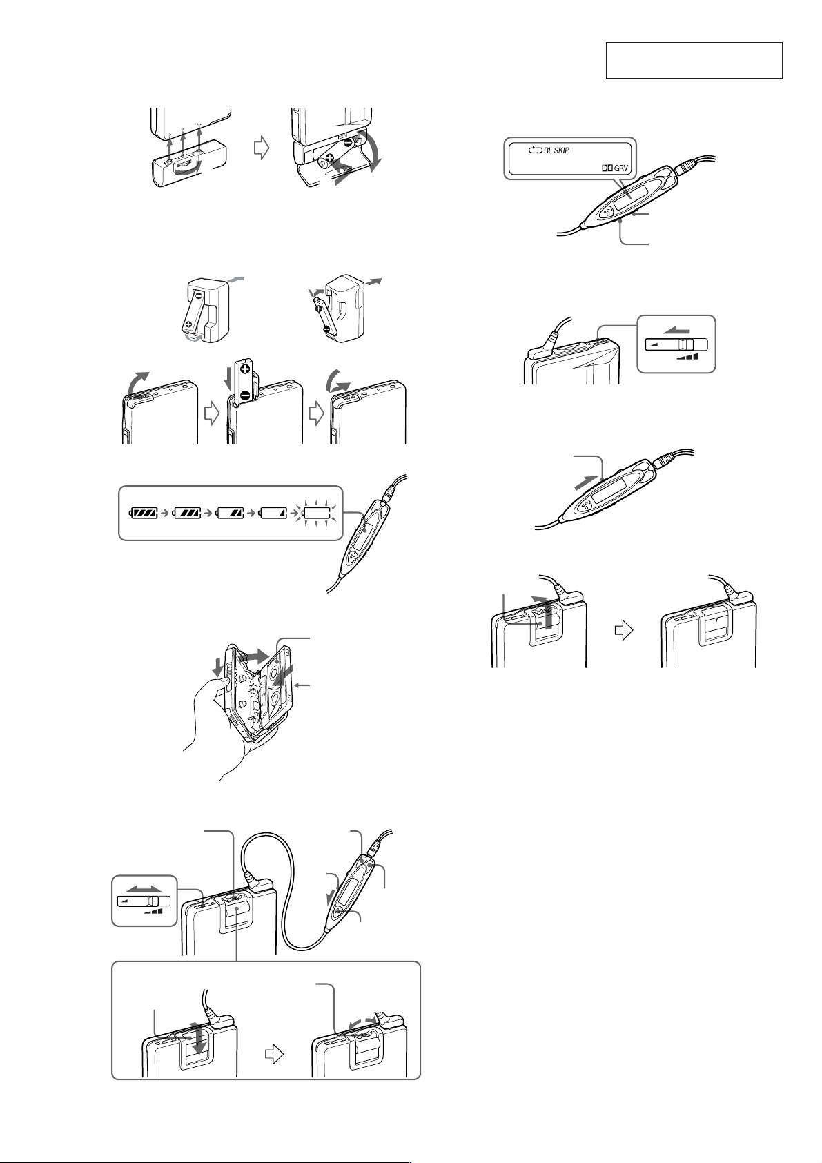
SECTION 2
A
UK, Australian, and Hong Kong
model
Modèle pour le Royaume-Unie,
l’Australie et Hong-Kong
Modell für GB, Australien und
Hongkong
Other models
Autres modèles
Andere Modelle
1
2
3
4
B
VOL
AVLS
OPEN
C
D
Y •x
FF (+)
REW (–)
Jog lever
Levier Jog
Jog-Hebel
FWD
REV
HOLD
Plug in firmly .
Branchez fermement.
Fest einstecken.
Hold shutter
Cache de
verrouillage
Schutzschieber
Jog lever
Levier Jog
Jog-Hebel
FF
REW
E
HOLD
MODE
SOUND
F
G
OPEN
Hold shutter
Cache de
verrouillage
Schutzschieber
VOL
AVLS
GENERAL
WM-EX910
This section is extracted from
instruction manual.
5
WM-EX910
• This set can be disassembled in the order shown below.
SECTION 3
DISASSEMBLY
SET CASE SECTION MAIN BOARD
LID SUB ASSY, CASSETTE
LEVER (N2)/(R2) ASSY, PINCH
Note: Follow the disassembly procedure in the numerical order given.
ORNAMENT (OPEN) BLOCK ASSY
HEAD, MAGNETIC (PLAYBACK) (HP901)
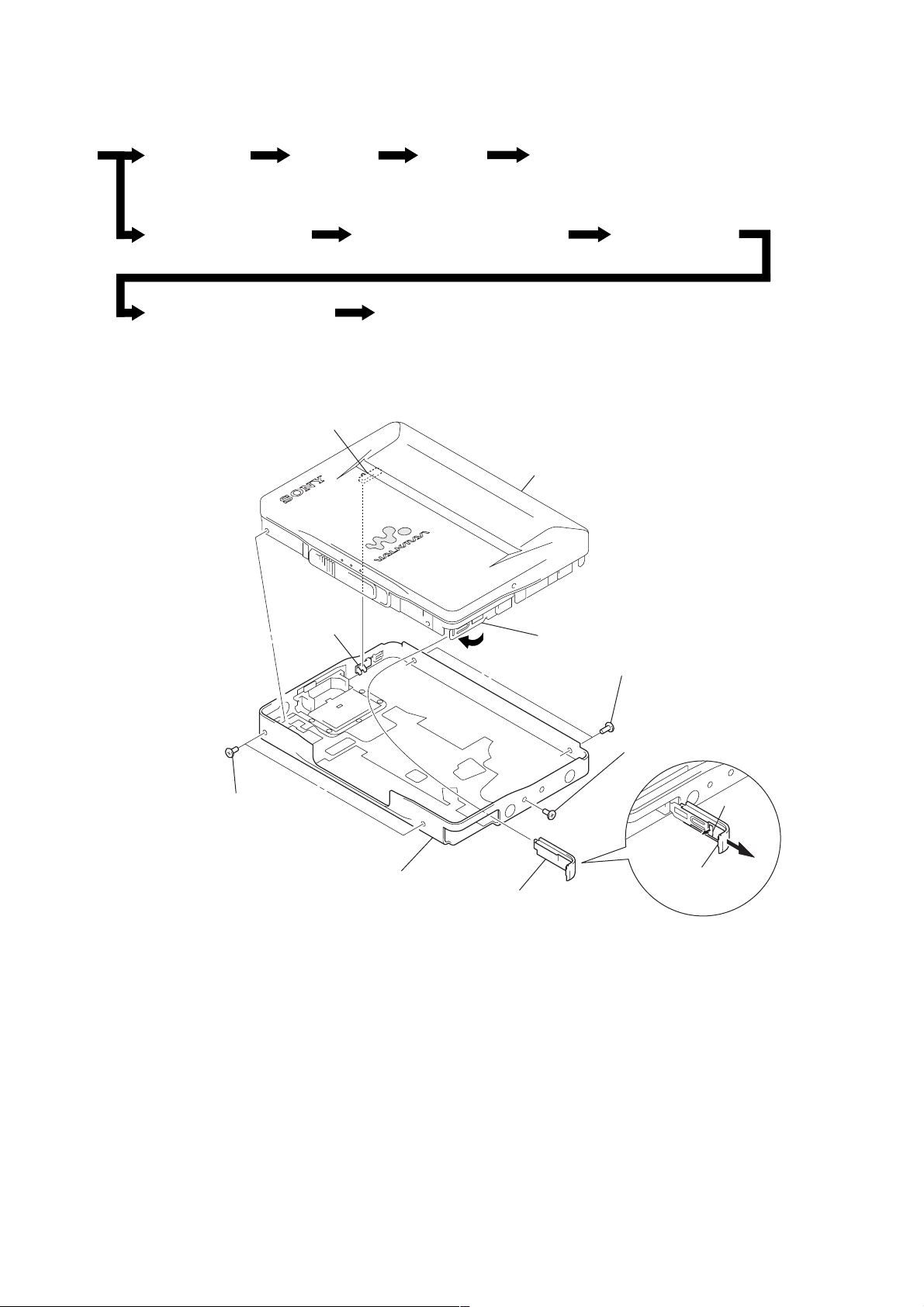
CASE SECTION
S701
Note:On installation
“lid assy, cassette” adjust
the S701 and knob (vol).
knob (vol)
BELT (F4) MOTOR, DC (CAPSTAN/REEL) (M601)
HOLDER (FA) ASSY
lid assy, cassette
4
Close terminal board assy.
5
two screws (MI)
7
case section
3
lid, battery case
5
two screws (MI)
6
screw (MI)
1
2
claw
open “lid, battery
case”.
6
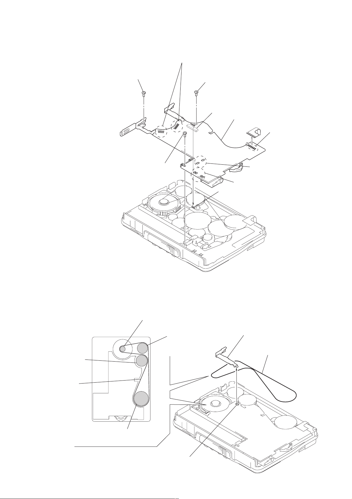
MAIN BOARD
2
screw
2
screw
1
Remove seven solders of “motor, DC (M601)”.
2
screw (M1.4) (toothed lock)
S702
3
MAIN board
1
1
Remove four solders of
slider
“switch, leaf (S704)”.
WM-EX910
1
Remove six solders of
head flexible board.
Remove two solders of
“solenoid, plunger”.
Note:On installation
MAIN board adjust
the S702 and slider.
BELT (F4)
flywheel (R),
insert
belt (F4)
pulley, motor
pulley, reverse
2
terminal board, battery
3
belt (F4)
flywheel (N), insert
1
Remove solder of
“terminal board, battery”.
7
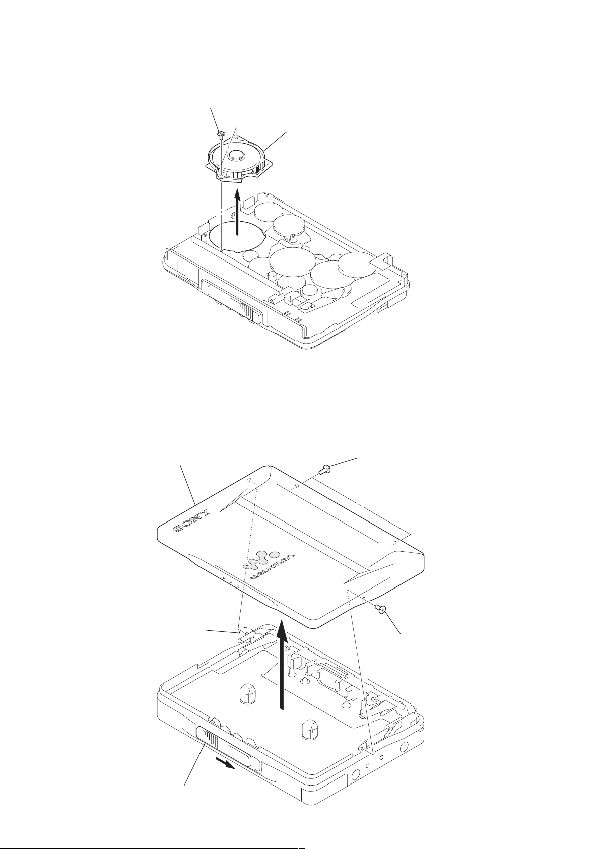
WM-EX910
)
w
MOTOR, DC (CAPSTAN/REEL) (M601)
1
two screws (M1.4)
2
motor, DC (capstan/reel) (M601
LID SUB ASSY, CASSETTE
4
lid sub assy, cassette
3
boss
2
two screws (MI)
2
scre
1
Open “lid assy, cassette”.
8
 Loading...