

Sony WMEX-660 Service manual
WM-EX660/EX662
SERVICE MANUAL
Dolby noise reduction manufactured under license
from Dolby Laboratories Licensing Corporation.
“DOLBY” and the double-D symbol a are trademarks of Dolby Laboratories Licensing Corporation.
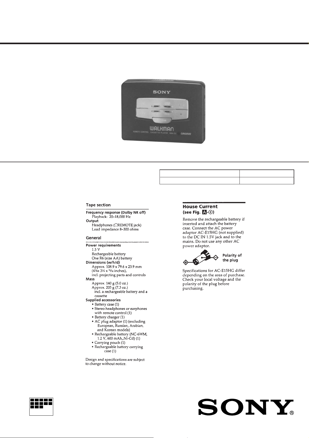
SPECIFICATIONS
AEP Model
UK Model
WM-EX660/EX662
E Model
WM-EX662
Model Name Using Similar Mechanism WM-EX650/EX652/EX654
Tape Transport Mechanism Type MT-WMEX550-125
MICROFILM
CASSETTE PLAYER

TABLE OF CONTENTS
1. SERVICING NOTES ............................................... 3
2. GENERAL ................................................................... 5
3. DISASSEMBLY ......................................................... 8
4. MECHANICAL ADJUSTMENTS....................... 13
5. ELECTRICAL ADJUSTMENTS......................... 13
6. DIAGRAMS
6-1. Block Diagram ................................................................ 14
6-2. Printed Wiring Board ...................................................... 16
6-3. Schematic Diagram ......................................................... 19
6-4. IC Pin Function Description ........................................... 25
7. EXPLODED VIEWS ................................................ 27
8. ELECTRICAL PARTS LIST ............................... 30
SAFETY-RELATED COMPONENT WARNING!!
COMPONENTS IDENTIFIED BY MARK ! OR DOTTED
LINE WITH MARK ! ON THE SCHEMATIC DIAGRAMS
AND IN THE PARTS LIST ARE CRITICAL TO SAFE
OPERATION. REPLACE THESE COMPONENTS WITH
SONY PARTS WHOSE PART NUMBERS APPEAR AS
SHOWN IN THIS MANUAL OR IN SUPPLEMENTS PUBLISHED BY SONY.
Flexible Circuit Board Repairing
• Keep the temperature of the soldering iron around 270 ˚C during repairing.
• Do not touch the soldering iron on the same conductor of the
circuit board (within 3 times).
• Be careful not to apply force on the conductor when soldering
or unsoldering.
Notes on chip component replacement
• Never reuse a disconnected chip component.
• Notice that the minus side of a tantalum capacitor may be damaged by heat.
– 2 –
SECTION 1
SERVICING NOTES
This set detects the rotation of GEAR (PH) using the PH701 (photo
reflector). The PH701 is mounted on the MAIN board, and therefore the GEAR cannot be detected with the MAIN board removed.
As a result, the motor cannot be controlled, causing malfunction.
Further, the S702 (FWD/REV switch) is also mounted on the MAIN
board, and with the board removed, the mechanism position
cannnot be detected and the operation is not changed over.
Therefore, when the voltage check is executed with the MAIN
board removed, follow the procedure provided below.
Note : Do not move the S702 swithc position when removing the MAIN
board.
If it is moved, the set will not be changed over to the selected mode.
In this case, reconnect the MAIN board to the set and retry the
work from the beginning.
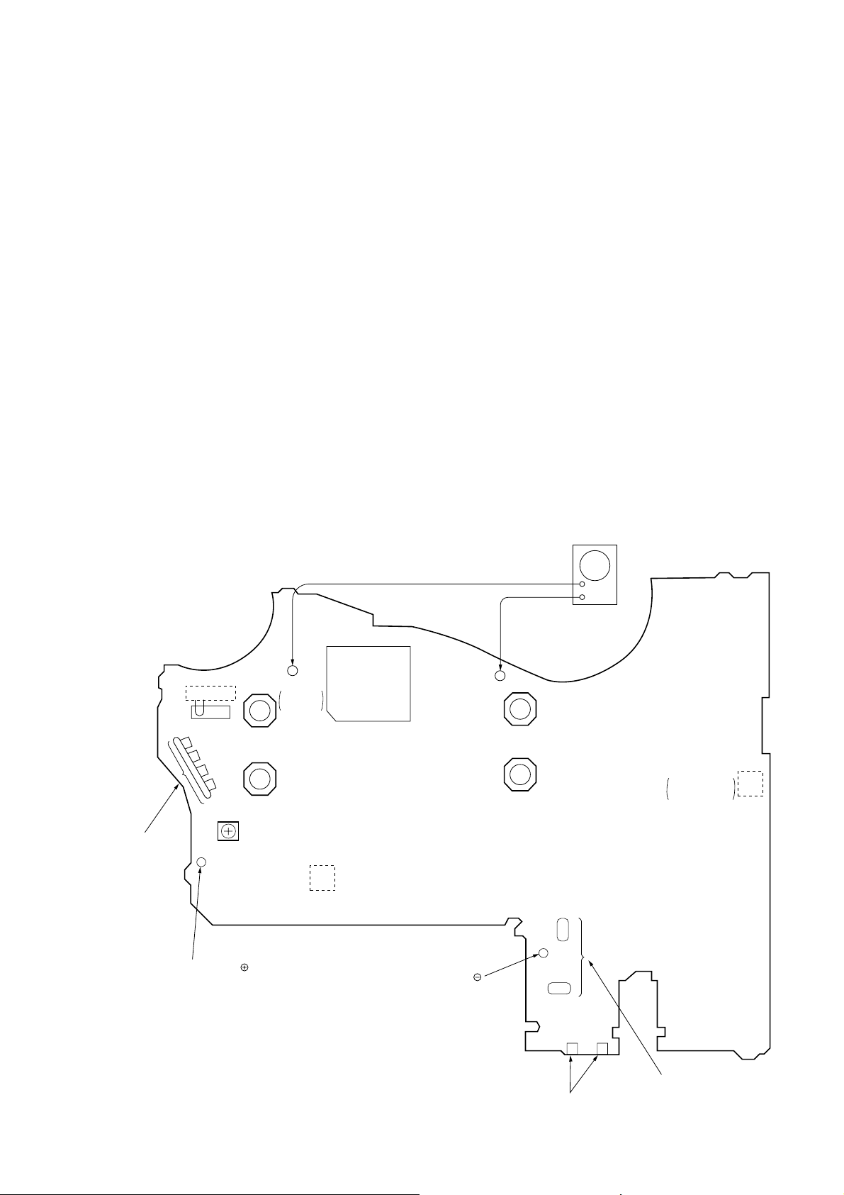
— MAIN BOARD (SIDE B) —
square wave
10 Hz, – 3.5 dB
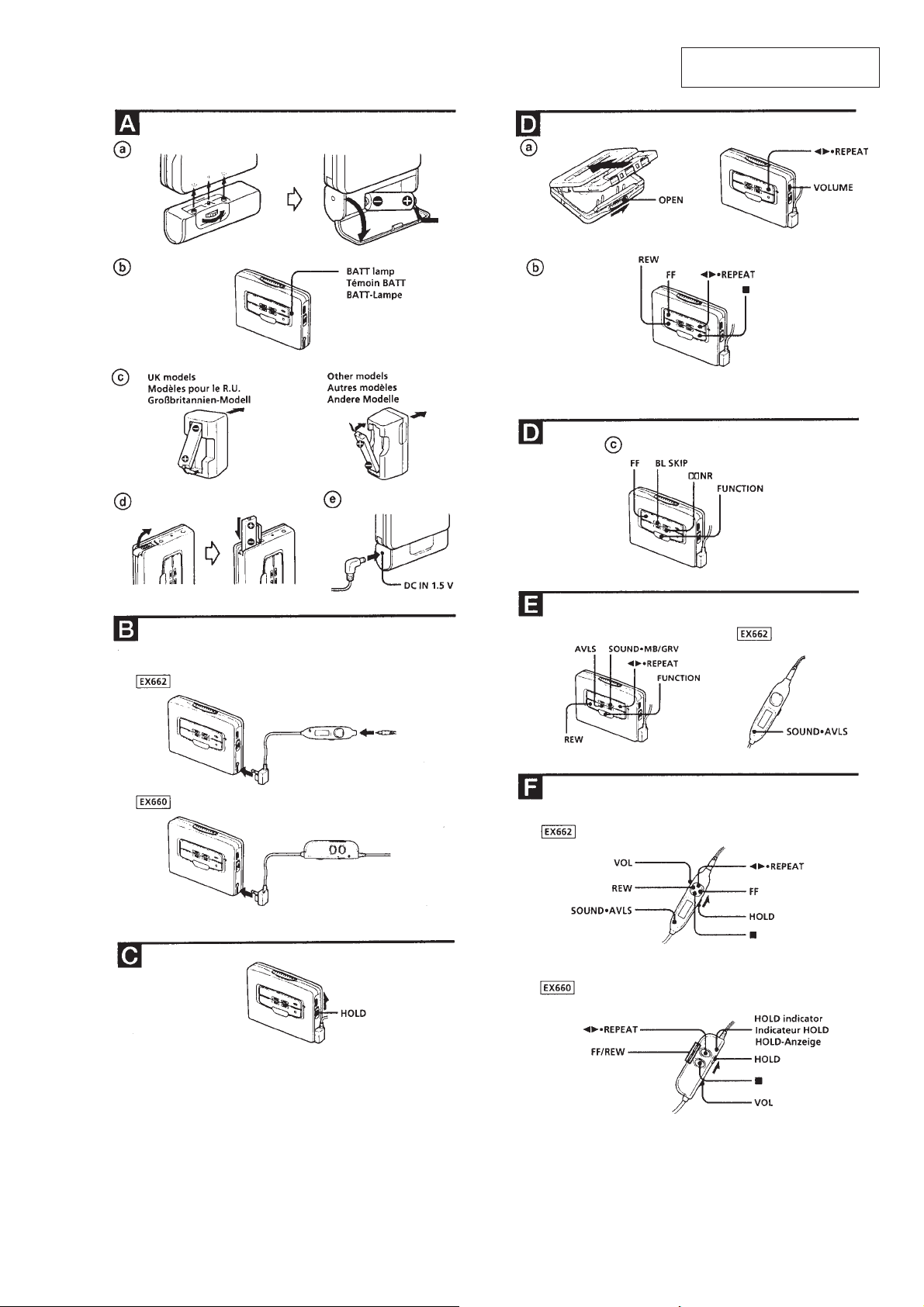
1. Setting
1) Refer to “3. DISASSEMBLY”, and remove the cabinet and
open the MAIN board.
2) Connect the MAIN board to the M901 (motor) and PM901
(plunger) using jumper wires.
3) Short the ATS terminals.
4) Press and fixed the S701 (CASSETTE HOLDER).
5) Supply 1.5V to the battery terminals ‘ and ’ using a stabilized power supply.
2. FF, REW Modes
1) Input a square wave to the TP35 (PHOTO IN) and TP23
(GND). (See figure below)
2) Press the S704 (STOP) for selecting STOP mode.
3) Press the S706 (FF) or S707 (REW).
3. PLAY mode
1) Input a square wave to the TP35 (PHOTO IN) and TP23
(GND). (See figure below)
2) Press the S704 (STOP) for selecting STOP mode.
3) Press the S705 (PLAY). (Each time the switch is pressed, the
mode is changed over.)
AF
oscillator
+
–
connect to
M901 (motor)
battery terminal
S702
FWD
→
REV
S706 (FF)
S707 (REW)
RV601
TP35
PHOTO
IN
PH701
IC701
battery terminal
TP23
(GND)
S705 (PLAY)
S704 (STOP)
S701
CASSETTE
HOLDER
– 3 –
ATS terminals
(to S901)
connect to
PM901 (plunger)
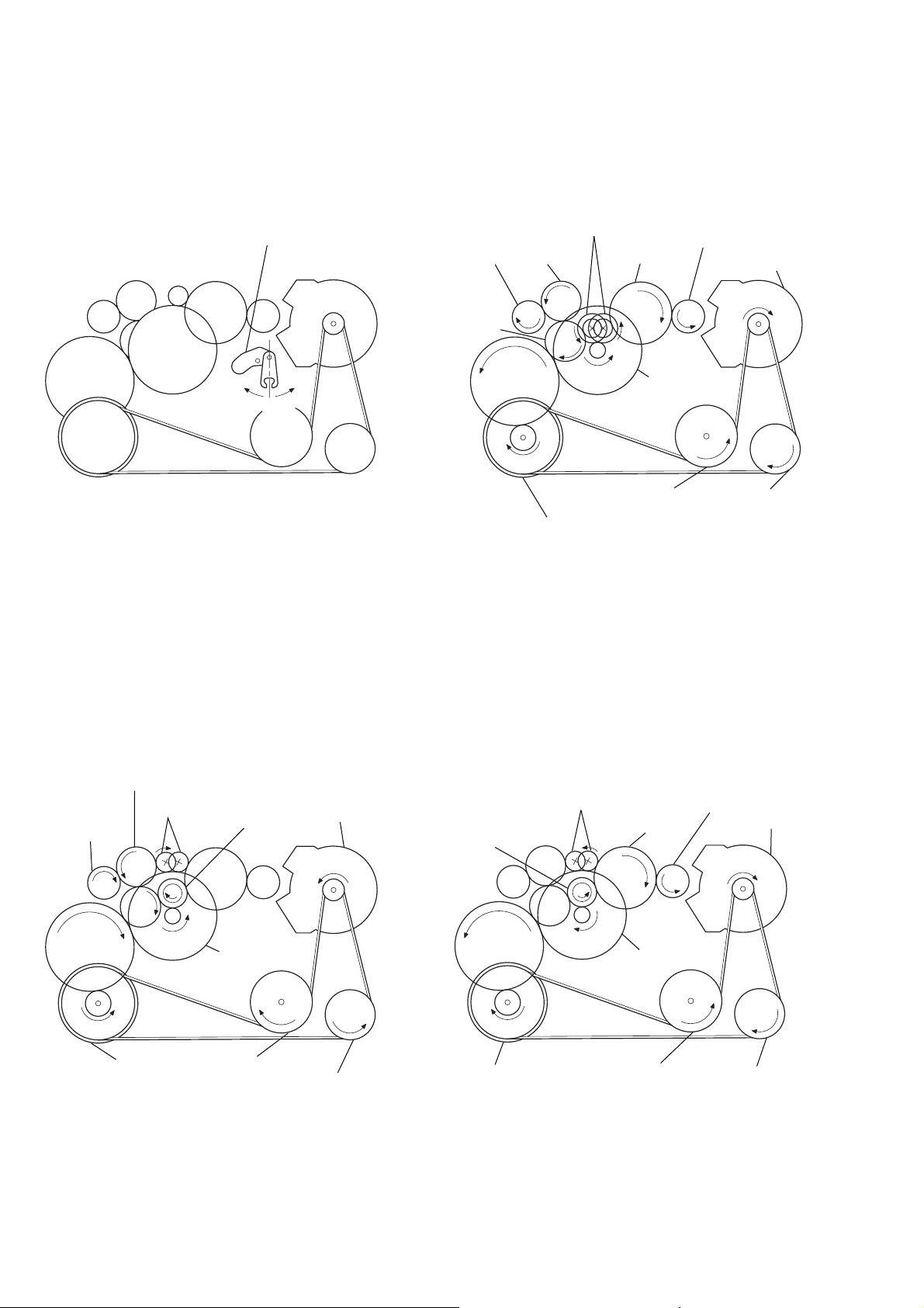
Lever (SW) Rotation system
y
Rotation system during PLAY.
lever (SW)
gear (REEL)
(T side)
gear (TA)
gear (TB)
gear (NR)
(REV: right side/
FWD: left side)
gear (S)
gear (REEL)
(S side)
motor pulle
Rotation system during FF.
gear (TB)
gear (FR)
gear (REEL)
(T side)
(FF: left side)
side R
side F
senter
gear (NR)
motor pulley
gear (Y)
flywheel (N) ass’y
Rotation system during REW.
gear (FR)
(REW: right side)
gear (NR)
clutch ass’y (M)
gear (S)
Pulley (reverse)flywheel (R) ass’y
gear (REEL)
(S side)
motor pulley
gear (Y)
flywheel (N) ass’y
clutch ass’y (M)
flywheel (R) ass’y
pulley (reverse)
gear (Y)
clutch ass’y (M)
flywheel (N) ass’y
flywheel (R) ass’y
pulley (reverse)
– 4 –
SECTION 2
GENERAL
This section is extracted from
instruction manual.
– 5 –
– 6 –
– 7 –

• This set can be disassembled in the order shown below.
SECTION 3
DISASSEMBLY
SET
Note: Follow the disassembly procedure in the numerical order given.
CASSETTE
LID ASS’Y
CASE (N) ASS’Y REEL ORNAMENT MAIN BOARD
CASSETTE LID ASS’Y
3
Remove the cassette lid ass’y to
direction of the arrow
A
.
NOTE FOR INSTALLATON
BELT
MAGNETIC HEAD (HP901)
2
screw (1.4 × 2)
MOTOR (M901)
1
Open the cassette lid ass’y.
2
screw (IB lock)
A
– 8 –
 Loading...