

Sony WMEX-610 Service manual
WM-EX610
SERVICE MANUAL
Ver 1.0 2000.10
Manufactured under license from Dolby Laboratories
Licensing Corporation.
“DOLBY” and the double-D symbol a are trademarks
of Dolby Laboratories Licensing Corporation.
Model Name Using Similar Mechanism NEW
Tape Transport Mechanism Type MT-WMEX610-162
AEP Model
UK Model
Chinese Model
Tourist Model
Frequency response (Dolby NR off)
Playback: 30 - 18 000 Hz
Output
Headphones (i jack)
Load impedance 8 - 300 Ω
Power requirements
1.5 V
Rechargeable battery
One R6 (size AA) battery
Dimensions (w/h/d)
Approx. 77.1 × 108.6 × 20.6 mm
SPECIFICATIONS
Mass
Approx. 160 g
Supplied accessories
• Battery case (1)
• Stereo headphones or earphones with remote control (1)
• Battery charger (1)
• Rechargeable battery (NC-6WM, 1.2 V, 600 mAh, Ni-Cd) (1)
• Carrying pouch (1)
• Rechargeable battery carrying case (1)
Design and specifications are subject to change without notice.
CASSETTE PLAYER

TABLE OF CONTENTS
1. SERVICE NOTE ······························································· 3
2. GENERAL ·········································································· 5
3. DISASSEMBLY
3-1. CASE SUB ASSY ·························································· 7
3-2. MAIN BOARD·······························································8
3-3. BELT (F4) ······································································· 8
3-4. MOTOR (M901) ·····························································9
3-5. LID ASSY, CASSETTE ················································· 9
3-6. ORNAMENT, REEL ···················································· 10
3-7. HOLDER (FS) ASSY ···················································10
3-8. LEVER (NA)/(RA) ASSY, PINCH ······························ 11
3-9. HEAD, MAGNETIC (HP901)······································ 11
4. MECHANICAL ADJUSTMENT ································ 12
5. ELECTRICAL ADJUSTMENT ·································· 12
6. DIAGRAMS
6-1. BLOCK DIAGRAM·····················································13
6-2. IC BLOCK DIAGRAMS·············································· 15
6-3. PRINTED WIRING BOARD·······································16
6-4. SCHEMATAC DIAGRAM ··········································· 19
6-5. IC PIN FUNCTION······················································22
7. EXPLODED VIEWS
7-1. CABINET BLOCK, MAIN BOARD ··························· 24
7-2. MECHANISM DECK BLOCK···································· 25
8. ELECTRICAL PARTS LIST ······································· 26
Notes on chip component replacement
• Never reuse a disconnected chip component.
• Notice that the minus side of a tantalum capacitor may be
damaged by heat.
Flexible Circuit Board Repairing
• Keep the temperature of soldering iron around 270˚C
during repairing.
• Do not touch the soldering iron on the same conductor of the
circuit board (within 3 times).
• Be careful not to apply force on the conductor when soldering
or unsoldering.
— 2 —
SAFETY-RELATED COMPONENT WARNING!!
COMPONENTS IDENTIFIED BY MARK ! OR DOTTED LINE WITH
MARK ! ON THE SCHEMATIC DIAGRAMS AND IN THE PARTS
LIST ARE CRITICAL TO SAFE OPERATION. REPLACE THESE
COMPONENTS WITH SONY PARTS WHOSE PART NUMBERS
APPEAR AS SHOWN IN THIS MANUAL OR IN SUPPLEMENTS
PUBLISHED BY SONY.
SECTION 1
SERVICE NOTE
[Service Mode]
The service mode enables to operate the mechanism of WM-EX610
while the MAIN board is opened.
Rotation of the idler gear (A) (S side) is detected using the photoreflector (PH701) in the WM-EX610. PH701 is located on the
MAIN board, therefore the rotation of the idler gear (A) (S side)
cannot be detected by PH701 when the MAIN board is removed.
As a result, the motor cannot be controlled and cannot run correctly .
To repair the machine after the MAIN board is removed while the
main power is turned on, follow the procedures as described below.
1. Setting
1) Remove the cabinets referring to section “3. DISASSEMBL Y”.
Open the MAIN board.
2) Connect the motor (M901) and the plunger solenoid (PM901)
to the MAIN board using the jumper wires. When the extension
jig (1-769-143-11) (10 wires as a set) is used, they can be
connected easily.
3) Short the TAPE DETECT switch (S901-1) and the ATS switch
(S901-2).
4) Connect an AF oscillator to TP53 (P. IN) and TP14 (GND).
5) Connect DC 1.3 V from e xternal regulated power supply to ‘
and ’ terminals of the battery.
2. PRE-SET status
The PLA Y, FF and REW modes can be entered only from the PRESET status.
1) Check that the slider (NR) is in the center position (S701), and
the FWD/REV switch is also in the center position. When
these switches are not in the center position, set them to the
PRE-SET status as follows.
2) Move the FWD/REV switch (S701) to the same position as the
slider (NR) is set.
3) The slider (NR) can be moved when the main power of the
regulated power supply is turned OFF once then back ON.
Move the FWD/REV switch (S701) to the center position in
synchronism with the timing when the slider (NR) is moved.
3. FF, REW modes
1) Check that the PRE-SET status is set.
2) Connect square wave or sine wave to TP53 (P. IN) and TP14
(GND). (See illustration below)
3) Press the x switch (S702) to enter the STOP mode.
4) Press the FF AMS switch (S704) and the REW AMS switch
(S705).
4. PLAY mode
1) Check that the PRE-SET status is set.
2) Connect square wave or sine wave to TP53 (P. IN) and TP14
(GND). (See illustration below)
3) Press the x switch (S702) to enter the stop mode.
4) When the nN switch (S703) of the MAIN board is pressed,
the slider (N/R) moves once to the F side then moves to the R
side. When the FWD/REV switch (S701) is pressed in the
synchronism with the above timing, the machine can enter the
PLAY (R side) mode. Press the nN switch (S703) again,
and move the FWD/REV switch (S701) in the synchronism
with the motion of slider (NR). It enables the machine to enter
into the PLAY (F side) mode.
Note 1: When you fail to enter the PLAY mode, re-start from step
1) PRE-SET status.
Note 2: Regarding the nN (S703), x (S702),
FF AMS (S704), and REW AMS (S705) switches, use
these switches of the remote control unit as much as possible.
Note 3: If a headphones are used, the beep sound shows the timing
of the FWD/REV switch (S701).
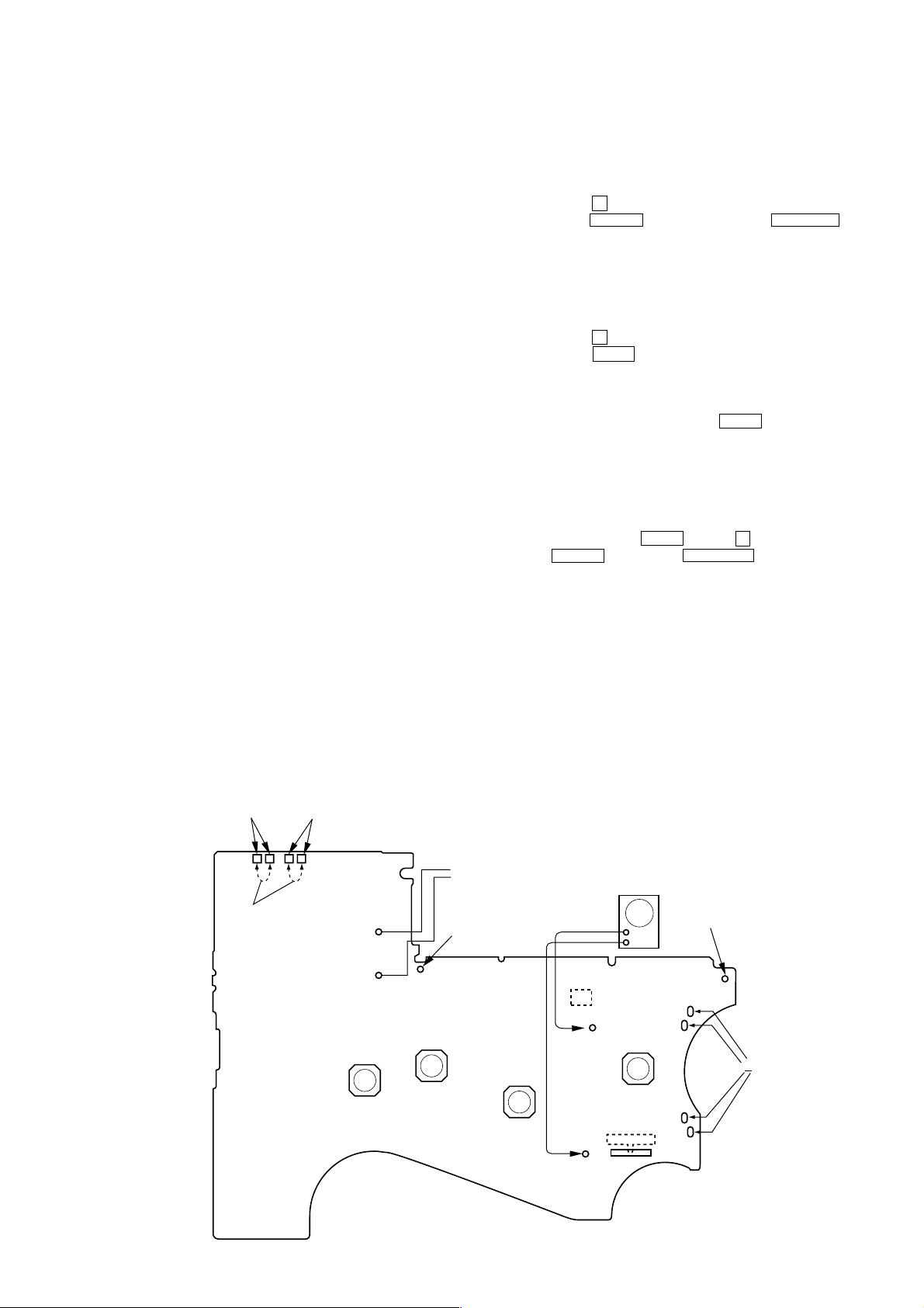
TAPE DETECT
SWITCH
(S901-1)
Short
ATS
SWITCH
(S901-2)
œ
REPEAT
(S703)
– MAIN BOARD (SIDE B) —
Plunger (PM901)
Square-wave (sine wave)
Battery terminal
p
(S702)
10 Hz, -3.5 dB
’
FF AMS
(S704)
AF OSC
+
–
PH701
REW AMS
TP53
(S705)
(P.IN)
S701
FWD←STOP→REV
TP14
(GND)
Battery terminal
M
‘
M901
— 3 —
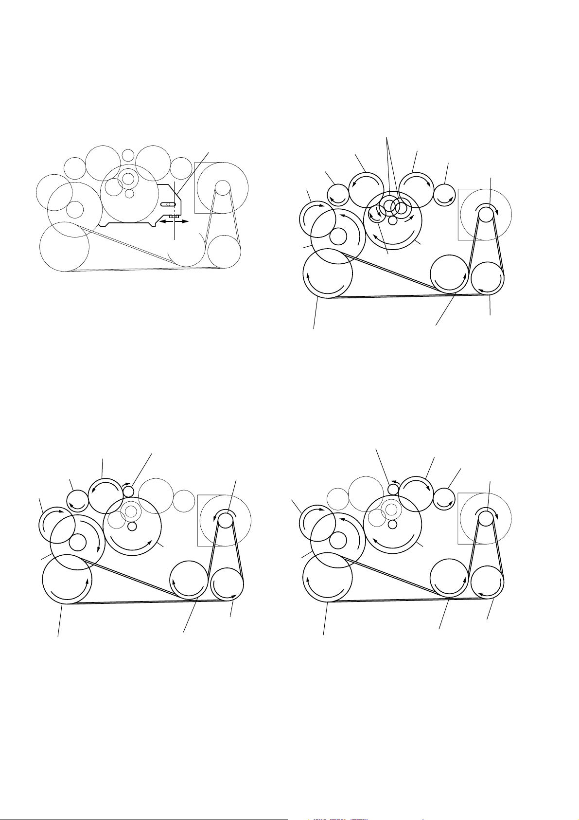
[ Slider (NR) ] [ Tape drive mechanism ]
y
Tape drive mechanism in PLAY mode
Gear (NR)
(FWD : Left side
REV : Right side)
Idler Gear
(A)(T side)
Gear
Idler Gear
F side
Center
Slider (NR)
(REEL)(T side)
Cam Gear
R side
Gear (Y)
Insert Flywheel (N)
Idler Gear (A)(S side)
Gear (REEL)(S side)
Motor Pulley
Clutch Assy
Pulley (Reverse)
Insert Flywheel (R)
Tape drive mechanism in FF mode Tape drive mechanism in REW mode
Gear (FR)
(REW : Right side)
Insert Flywheel (R)
Gear
(REEL)(T side)
Cam Gear
Gear (Y)
Insert Flywheel (N)
Idler Gear
(A)(T side)
Gear (FR)
(FF : Left side)
Clutch Assy
Insert Flywheel (R)
Motor Pulle
Pulley (Reverse)
Cam Gear
Gear (Y)
Insert Flywheel (N)
Idler Gear
(A)(S side)
Clutch Assy
Gear
(REEL)(S side)
Motor Pulley
Pulley (Reverse)
— 4 —
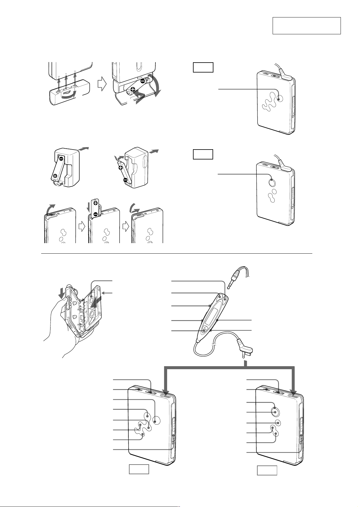
1
B
UK, Australian, and
Hong Kong model
2
4
Other models
SECTION 2
GENERAL
3
This section is extracted
from instruction manual.
CA
EX615
BATT
EX610
BATT
HOLD
VOL
BATT
Y•REPEAT
FF•CUE
REW•REVIEW
OPEN
Plug in firmly.
REV
FWD
x
REW (–)
FF (+)
VOL
HOLD
Y•x
SOUND
MODE
HOLD
i
Y•REPEAT
FF•CUE (AMS)
REW•REVIEW (AMS)
VOL
BATT
x
OPEN
i
EX615
EX610
— 5 —
Preparations
Prepare a dry battey (not supplied) or the
rechargeable battery (supplied).
Dry Battery A
Attach the supplied battery case, and then insert one
R6 (size AA) battery with correct polarity.
Note
•For maximum performance we recommend that you
use a Sony alkaline battery.
Rechargeable Battery B
1Insert the supplied rechargeable battery (NC-6WM)
into the charger with correct polarity.
2Plug in the charger to the house current (mains).
UK, Australian, and Hong Kong model: Full
charging takes about 3.5 hours.
U.S.A., Canada, European Continent and Saudi
Arabian model: Full charging takes about 2.5
hours.
Korean model: The full charging time depends on
the voltage of your mains.
110 V: 10 hours
220 V: 2.5 hours
Other models: The full charging time depends on
the voltage of your mains.
120 V: 10 hours
220 – 240V: 2.5 hours
3Insert the fully charged battery into the
rechargeable battery compartment.
You can charge the battery about 300 times.
When to replace/charge the battery C
Replace or charge the battery when “e” flashes in
the display on the remote control and the BATT lamp
on the main unit goes out.
Note
•After the battery is replaced, the setting of the
SOUND and MODE buttons will be erased.
Playing a Tape
1 Insert a cassette and if the HOLD function is
on, slide the HOLD switch in the opposite
direction of the arrow to unlock the controls.
2 Press Y(play)•x(stop) on the remote
control and adjust the volume with VOL.
(On the main unit, press Y•REPEAT.)
When adjusting the volume on the main unit
Set the VOL control on the remote control at maximum.
When adjusting the volume on the remote control
Set the VOL control on the main unit to around 6.
Operation on the remote control
To
Switch playback to the
other side
Stop playback
Fast forward*
Rewind*
Repeat the current track
(Repeat Single Track
function)
Press
Y•x more than a second
during playback
Y•x once during
playback
FF during stop
REW during stop
Y•x twice during
playback
To stop a single repeat, press
Y•x once
Operation on the main unit
To
Switch playback to the
other side
Stop playback
Fast forward*
Rewind*
Repeat the current track
(Repeat Single Track
function)
* If Y•x on the remote control is pressed during fast
forward or rewind, the Walkman switches to
playback.
Press
Y•REPEAT during
playback
x
FF•CUE during stop
REW•REVIEW during stop
Y•REPEAT for 2 seconds
or more during playback
To stop a single repeat, press it
again.
Other tape operations
Use the FF/REW buttons on the remote control, or
FF•CUE (AMS)/REW•REVIEW(AMS) on the main
unit.
To
Fast forward while
listening to the sound
(CUE)
Rewind while listening
to the sound (REVIEW)
Play the next track/
succeeding 9 tracks
from the beginning
(AMS*)
Play the current track/
previous 8 tracks from
the beginning (AMS*)
Play the other side from
the beginning (Skip
Reverse function)
Play the same side from
the beginning (Rewind
Auto Play function)
* Automatic Music Sensor
Press
Press and hold FF during
playback and release it at
the point you want.
Press and hold REW during
playback and release it at
the point you want.
FF once/repeatedly during
playback
REW once/repeatedly
during playback
FF for 2 seconds or more
during stop
REW for 2 seconds or more
during stop
Using Other Functions
Adjusting Playback Mode
You can adjust the playback direction mode (s or
d) as well as the BL SKIP mode (on or off).
1Press MODE repeatedly. With each press the
indications change as follows:
B
s
v
s BL SKIP
v
d
v
d BL SKIP
•When “BL SKIP” is displayed, the tape is fastforwarded to the next track if there is a blank space
of longer than 12 seconds. You will hear repeated
sets of three short beeps when skipping a blank.
•When “s” is displayed, both sides of the tape is
played repeatedly.
•When “d” is displayed, both sides of the tape is
played once (if you start from R (REV) side, only
REV side will be played).
Note
• You cannot adjust the playback mode during fastforward or rewind.
Playing a Tape Recorded with the
Dolby* B NR System
Hold down SOUND until “;” appears in the
display.
To cancel Dolby B NR, hold down SOUND again
until “;” disappears.
* Manufactured under license from Dolby Laboratories.
“Dolby”and the double-D symbol are trademarks of
Dolby Laboratories.
Note
• You cannot turn on/off the Dolby B NR function
during fast-forward or rewind.
Emphasizing Sound
1Press SOUND repeatedly. With each press, the
indications change as follows:
RV (Sound Revitalizer): emphasizes treble sound
MB (Mega Bass): emphasizes bass sound
(moderate effect)
GRV (Groove): emphasizes bass sound
(strong effect)
none: normal (no effect)
Notes
•If the sound is distorted with the mode “GRV”, turn
down the volume of the main unit or select other
modes.
• You cannot change the mode during fast-forward or
rewind.
Protecting Your Hearing — AVLS
(Automatic Volume Limiter System)
Hold down MODE until “AVLS” appears in the
display.
To cancel the AVLS function, hold down MODE
again until “AVLS” disappears.
Note
•You cannot turn on/off the AVLS function during fastforward or rewind.
Locking the Controls
— HOLD Function
Slide the HOLD switch in the direction of the arrow
to lock the controls of the Walkman or the remote
control.
— 6 —
SECTION 3
b
c
DISASSEMBLY
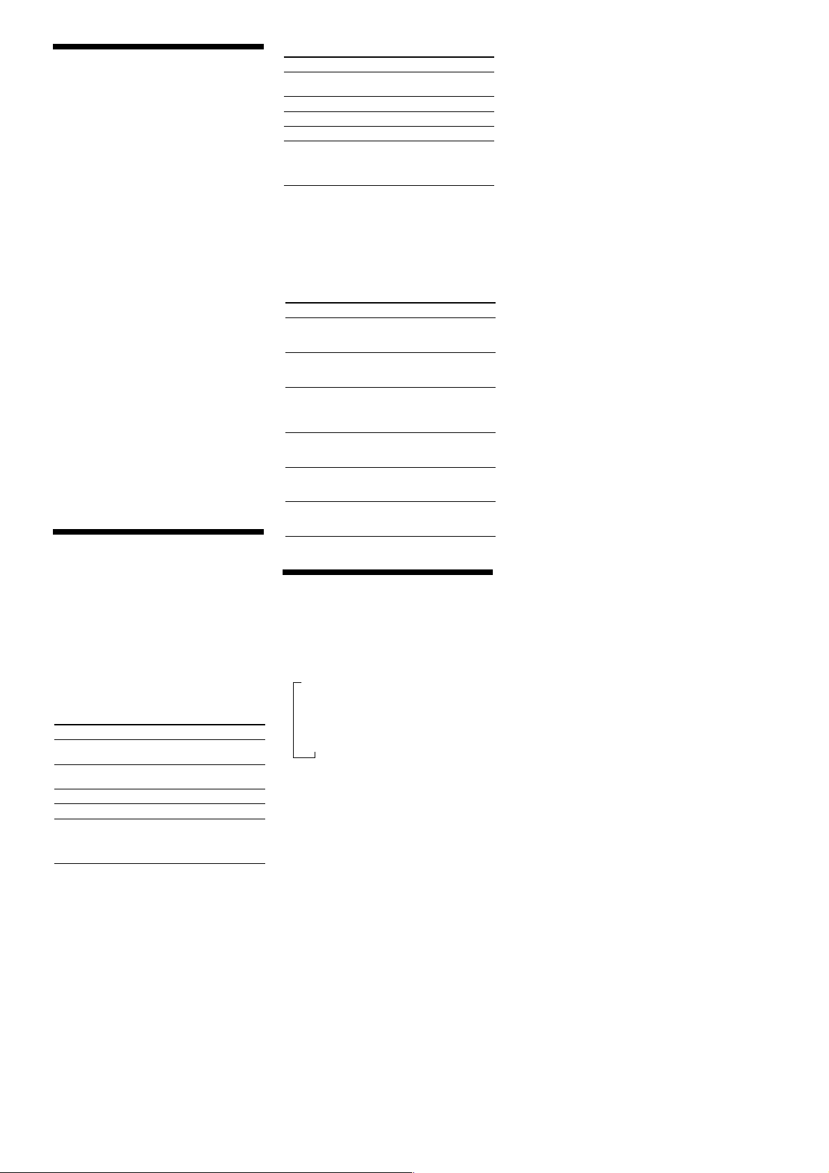
Note : Follow the disassembly procedure as shown in the flow chart below.
Set
Case sub
assy
Lid assy,
cassette
Main board
Ornament,
reel
Belt (F4)
Holder (FS)
assy
Note : Follow the disassembly procedure in the numerical order given.
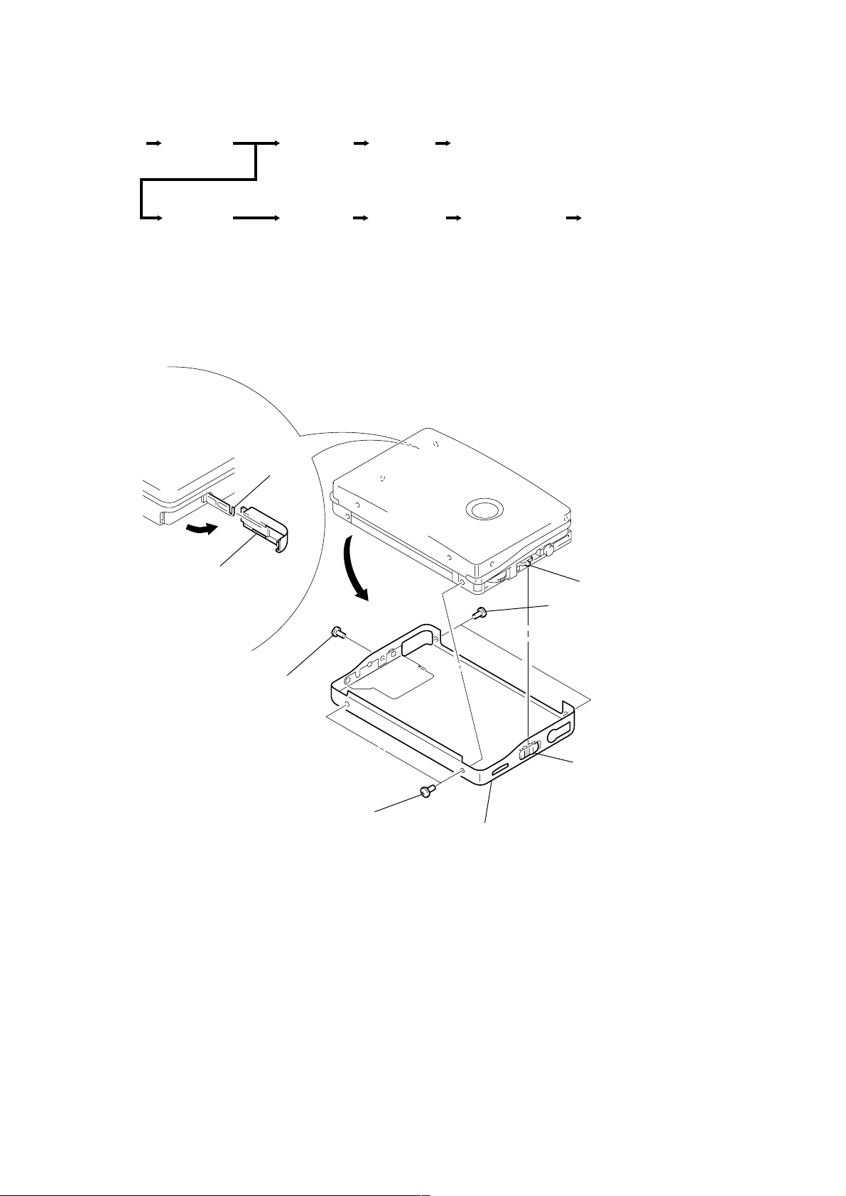
3-1. CASE SUB ASSY
Claw
Motor (M901)
Lever (NA)/(RA)
assy, pinch
Head, magneti
(HP901)
1
Lid, battery case
2
Screw
(M1.4
×
2.5)
4
Two screws
(M1.4
×
2.5)
3
(M1.4
5
Remove the case sub assy
in the direction of the arrow.
S707
Two screws
×
2.5)
knob (HOLD)
Note: When assembling the case su
assy, align the knob (HOLD)
with the position of S707.
— 7 —
 Loading...