

Sony WMEX-526 Service manual
WM-EX526
SERVICE MANUAL
Ver 1.0 2002.01
SPECIFICATIONS
• Frequency response
Playback: 30 - 18 000 Hz
• Output
Headphones (i jack)
Load impedance 8 – 300 Ω
• Power requirements
1.5 V
One R6 (size AA) battery
• Dimensions (w/h/d)
Approx. 78.1 x 108.0 x 28.1 mm (excluding projecting parts
and controls)
• Mass
Approx. 161 g (main unit only)
• Supplied accessories
Stereo headphones or earphones with remote control (1)
Design and specifications are subject to change without notice.
E Model
Model Name Using Similar Mechanism WM-EX506
Tape Transport Mechanism T ype MT-WMEX505-162
Battery life (Approx. hours) (JEITA*)
Tape playback 35
* Measured value by the standard of JEITA(Japan Electronics
and Information Technology Industries Association) (Using
a Sony HF series cassette tape).
**When using a Sony LR6(SG) “STAMINA” alkaline dry
battery(produced in Japan).
Note
• The battery life may be shorter depending on the
operating condition, the surrounding temperature
and battery type.
Sony alkaline LR6 (SG)**
9-873-468-01 Sony Corporation
2002A0500-1 Personal Audio Company
C 2002.1 Published by Sony Engineering Corporation
CASSETTE PLAYER

WM-EX526
TABLE OF CONTENTS
1. SERVICING NOTES ............................................... 3
2. GENERAL ................................................................... 5
3. DISASSEMBLY
3-1. Disassembly Flow ........................................................... 6
3-2. Lid Cassette Assy............................................................ 6
3-3. Case Block Assy.............................................................. 7
3-4. Reel Ornament Block Assy............................................. 7
3-5. Battery Holder ................................................................. 8
3-6. Belt (F2) .......................................................................... 8
3-7. MAIN Board ................................................................... 9
3-8. Motor (Capstan/Reel) (M901) ........................................ 10
3-9. Holder (FS) Assy............................................................. 10
3-10. Pinch Lever (N) Assy, Pinch Lever (R) Assy ................. 11
3-11. Magnetic Head (Playback) (HP901) .............................. 11
4. MECHANICAL ADJUSTMENTS....................... 11
5. ELECTRICAL ADJUSTMENTS......................... 11
6. DIAGRAMS
6-1. Block Diagram ................................................................ 12
6-2. Note for Printed Wiring Board and
Schematic Diagram ......................................................... 13
6-3. Printed Wiring Board ...................................................... 14
6-4. Schematic Diagram ......................................................... 15
6-5. IC Pin Function Description ........................................... 16
Flexible Circuit Board Repairing
• Keep the temperature of the soldering iron around 270 ˚C during repairing.
• Do not touch the soldering iron on the same conductor of the
circuit board (within 3 times).
• Be careful not to apply force on the conductor when soldering
or unsoldering.
Notes on chip component replacement
• Never reuse a disconnected chip component.
• Notice that the minus side of a tantalum capacitor may be damaged by heat.
7. EXPLODED VIEWS
7-1. Case Section .................................................................... 18
7-2. Mechanism Deck Section (MT-WMEX505-162) .......... 19
8. ELECTRICAL PARTS LIST ............................... 20
2
SECTION 1
e
SERVICING NOTES
WM-EX526
This set detects the rotation of the idler gear (A) (side S) using the
PH701 (photo reflector). The PH701 is mounted on the MAIN
board, therefore the idler gear (A) (side S) cannot be detected with
the MAIN board removed. As a r esult, the motor (M901) cannot
be controlled, causing malfunction.
Further, the DIRECTION switch (S701) is also mounted on the
MAIN board, and with the board removed, the mechanism position cannot be detected and the operation is not changed over.
Therefor, when the voltage check is e xecuted with the MAIN board
removed, follow the procedure provided below.
1. Setting
(1) Refer to “3. DISASSEMBLY”, and remove the MAIN board.
(2) Connect the MAIN board to the motor (M901) and the
plunger (PM901) using jumper wires. These can be connected
easily with the use of the extension tool (Part No. 1-769143-11) (ten in one set).
(3) Short the TAPE DETECT switch (S901-1) ter minals and the
ATS switch (S901-2) terminals.
(4) Connect the AF oscillator to the TP36 (PHOTO IN) and the
TP46 (GND).
(5) Supply 1.3 V to the battery terminals using the regulated
power supply.
2. Preset state
T o set the PLAY , FF, REW modes, the preset state must be set.
(1) Check that the slider (NR) and the DIRECTION switch
(S701) are set to the center position. If not, set the preset
state as follow.
(2) Move the DIRECTION switch (S701) to the side, which the
slider (NR) is facing.
(3) The slider (NR) will move when the regulated power supply
switch is set to OFF once and then set to ON. Move the DIRECTION switch (S701) according to this timing and set to
the center position.
3. FF, REW modes
(1) Check that the preset state is set.
(2) Input the square wave or sine wave to the TP36 (PHO T O IN)
and the TP46 (GND).
(3) Press the x button (S702) to set the STOP mode.
(4) Press the [FF] button (S704) or the [REW] button (S705).
4. PLAY mode
(1) Check that the preset state is set.
(2) Input the square wave or sine wave to the TP36 (PHO T O IN)
and the TP46 (GND).
(3) Press the x button (S702) to set the STOP mode.
(4) Press the [ REPEAT] button (S703) will move the
n N
slider (NR) once towards the side R and then to the side F.
Move the DIRECTION switch (S701) according to this
timing will set the PLAY mode (side F). Press the
n N
[ REPEAT] button (S703) another time and move the
DIRECTION switch (S701) according to the movement of
the slider (NR) will set the PLAY (R mode).
Note 1: If the above fails, perform from preset again.
Note 2: Use the [ REPEAT] (S703), x (S702), [FF] (S704),
and [REW] (S705) buttons on the remote controller as much as
possible. If no remote controller, do not touch the buttons with
your hands, but using a stick with a round tip.
Note 3: When using headphones, the timing for move the DIRECTION
switch (S701) can be determined from the beep sound.
n N
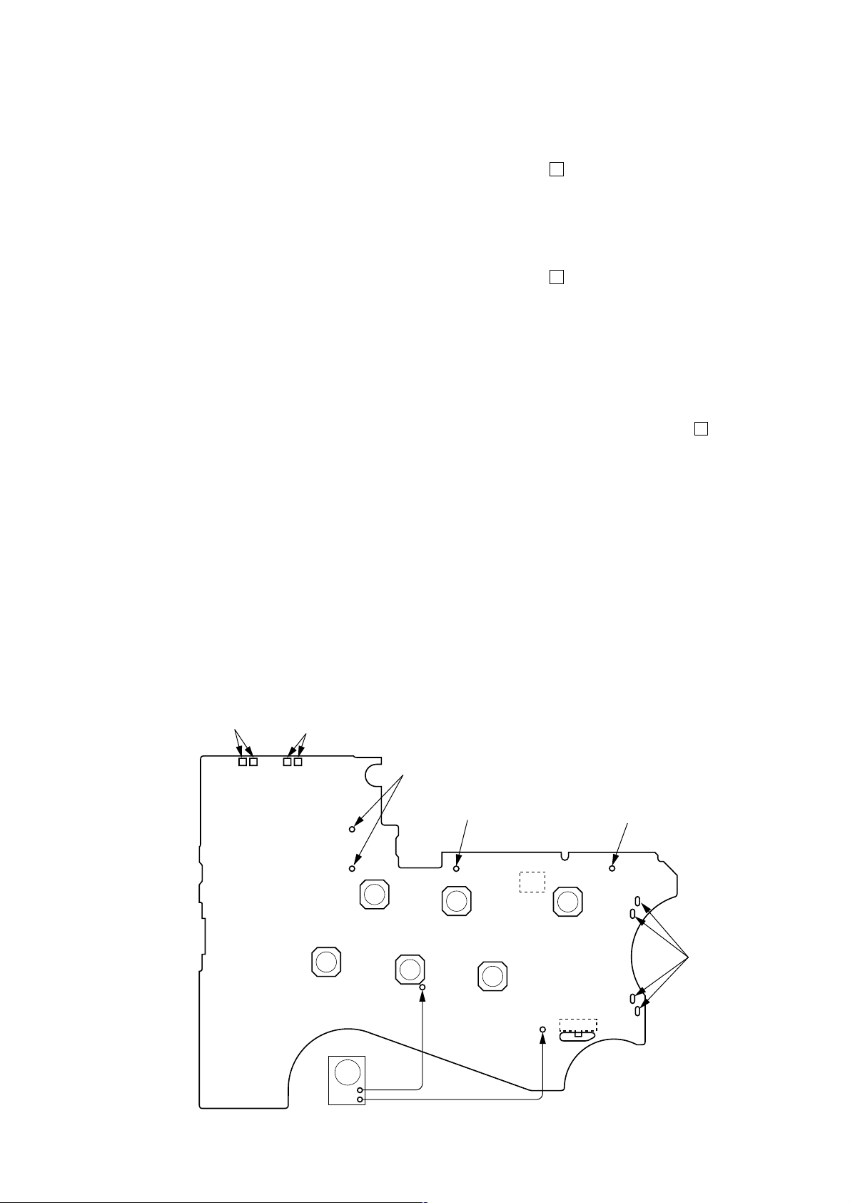
– MAIN Board (Side B) –
TAPE DETECT
switch
(S901-1)
ATS switch
(S901-2)
Y
FF
(S704)
REPEAT
(S703)
AF oscillator
connect to the plunger
(PM901)
battery
terminal
REW
(S705)
TP36
(PHOTO IN)
3
x
(S702)
FUNCTION
(S708)
PH701
FWD
TP46
(GND)
SOUND
(S706)
S701
DIRECTION
T
CENTERtREV
battery
terminal
#
connect to th
motor (M901)
+
–
square wave
(sine wave)
10 Hz, – 3.5 dB
3
WM-EX526
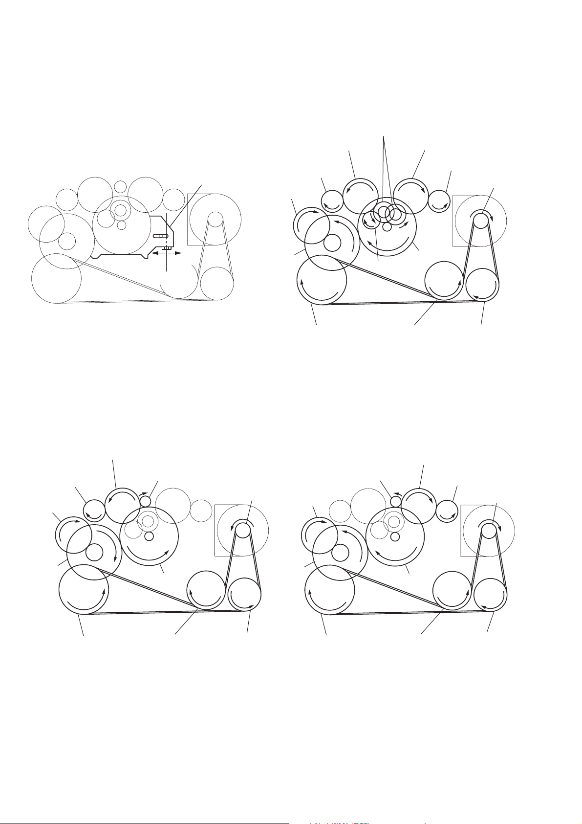
g
y
SLIDER (NRA) Rotation system
Rotation system during PLAY
idler (A) gear (T side)
gear (NR)
(FWD: left side
REW: right side)
idler (A) gear (S side)
gear (REEL) (T side)
cam gear
gear (Y)
insert flywheel (N)
idler (B) gear
insert flywheel (R)
side F
slider (NRA)
side R
center
Rotation system during FF Rotation system during REW
gear (REEL) (S side)
motor pulle
clutch assy (F)
reverse pulley
gear (REEL)
(T side)
cam gear
ear (Y)
idler (A) gear (T side)
insert flywheel (N)
gear (FR)
(FF: left side)
clutch assy (F)
insert flywheel (R)
motor pulley
reverse pulley
cam gear
gear (Y)
gear (FR)
(REW: right side)
insert flywheel (N)
idler (A) gear (S side)
gear (REEL) (S side)
clutch assy (F)
insert flywheel (R)
motor pulley
reverse pulley
4
SECTION 2
GENERAL
WM-EX526
This section is extracted from
instruction manual.
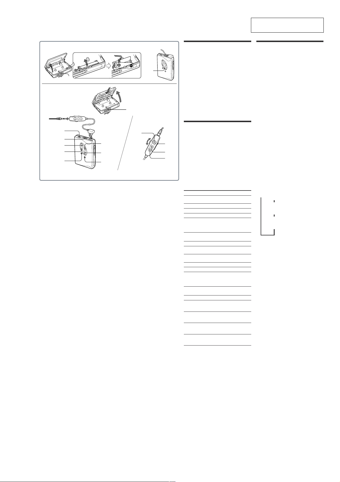
A
OPEN
OPEN
Plug in firmly.
VOL*
HOLD
Y•REPEAT**
REW (AMS•AVLS)
FUNCTION
* There is a tactile dot beside VOL on the main unit to show the direction to turn up the volume.
** The button has a tactile dot.
FF (AMS•
BL SKIP/s)
x
SOUND
Y•x**
B
BATT
VOL
HOLD
FF
REW
Preparations
To Insert battery
1 Slide the OPEN switch to open the cassette
holder.
2 Release the catch to open the battery
compartment lid, and insert one R6 (size
AA) dry battery with correct polarity.
Note
• For maximum performance we recommend that you
use a Sony alkaline battery.
When to replace the battery
Replace the battery with a new one when the BATT
lamp goes out.
Note
•After the battery is replaced, the settings of the
FUNCTION and SOUND buttons will be erased.
A
B
Playing a Tape
1 If the HOLD function is on, slide the HOLD
switch in the opposite direction of the
arrow to unlock the controls.
2 Insert a cassette and press Y•REPEAT on
the main unit, or if using the remote
control, press Y (play)•x (stop).
Adjust the volume with VOL.
When adjusting the volume on the main unit
Set the VOL control on the remote control at maximum.
When adjusting the volume on the remote control
Set the VOL control on the main unit slightly above the
appropriate level.
Operation on the main unit
To
Switch playback to the
other side
Stop playback
Fast forward*
Rewind*
Repeat the current track
(Repeat Single Track
function)
Operation on the remote control
To
Switch playback to the
other side
Stop playback
Fast forward*
Rewind*
Repeat the current track
(Repeat Single Track
function)
Other Tape Operations
To
Play the next track/
succeeding 9 tracks from
the beginning (AMS**)
Play the current track/
previous 8 tracks from the
beginning (AMS**)
Play the other side from the
beginning (Skip Reverse
function)
Play the same side from the
beginning (Rewind Auto
Play function)
* If Y•x on the remote control is pressed during fast
forward or rewind, the Walkman switches to
playback.
** Automatic Music Sensor
Press
Y•REPEAT during
playback
x
FF during stop
REW during stop
Y•REPEAT one second
or more during playback
To stop a single repeat, press
it again.
Press
Y•x one second or
more during playback
Y•x once during
playback
FF during stop
REW during stop
Y•x twice during
playback
To stop a single repeat, press
Y•x once.
Press
FF once/repeatedly
during playback
REW once/
repeatedly during
playback
FF one second or
more during stop
REW one second or
more during stop
Using Other Functions
Adjusting playback mode
While holding down FUNCTION, press the
FF button. The BL SKIP/s lamp will
light as long as FUNCTION is pressed.
Both sides of the tape is played repeatedly
(s mode), and the tape are fastforwarded to the next track if there is a
blank space.
To cancel the BL SKIP/s mode, hold
down FUNCTION and then press FF. The
BL SKIP/s lamp goes out.
Both sides of the tape are played once (if
you start from the reverse side (opposite to
the lid), only that side will be played).
Protecting Your Hearing (AVLS)
When AVLS (Automatic Volume Limiter System) is
turned on, the maximum volume is kept down to
protect your ears.
While holding down FUNCTION, press
REW. The AVLS lamp will light as long as
FUNCTION is pressed.
To cancel the AVLS, while holding down
FUNCTION, press REW. The AVLS lamp
goes out.
Notes on FUNCTION
• When FUNCTION is pressed, the LED lamp will light
to show the present mode.
• When you enter a function mode, you will hear a
short beep and when you cancel it, you will hear two
short beeps.
Emphasizing Bass
Press SOUND. Each time you press the
button, the SOUND mode changes as
below.
, NORM (normal): off
m a short beep
MB (Mega bass): emphasizes bass
m a long beep
GRV (Groove): emphasizes deeper
Notes
• If the sound is distorted with the mode “GRV”, turn
down the volume of the main unit or select other
modes.
• Bass emphasis may not show great effect if the
volume is turned up too high.
Locking the controls — HOLD
Function
Slide the HOLD switch in the direction of the arrow
to lock the controls.
sound
bass sound
two short beeps
5
WM-EX526
s
• This set can be disassembled in the order shown below.
3-1. DISASSEMBLY FLOW
Note 1: The process described in can be performed in any order.
Note 2: Without completing the process described in , the next process can not be performed.
SET
SECTION 3
DISASSEMBLY
3-2. LID CASSETTE ASSY
(Page 6)
3-4. REEL ORNAMENT BLOCK ASSY
(Page 7)
3-9. HOLDER (FS) ASSY
(Page 10)
3-10. PINCH LEVER (N) ASSY,
PINCH LEVER (R) ASSY
(Page 11)
3-11. MAGNETIC HEAD (PLAYBACK) (HP901)
(Page 11)
3-3. CASE BLOCK ASSY
(Page 7)
3-5. BATTERY HOLDER
(Page 8)
3-7. MAIN BOARD
(Page 9)
3-8. MOTOR (CAPSTAN/REEL) (M901)
(Page 10)
3-6. BELT (F2)
(Page 8)
Note: Follow the disassembly procedure in the numerical order given.
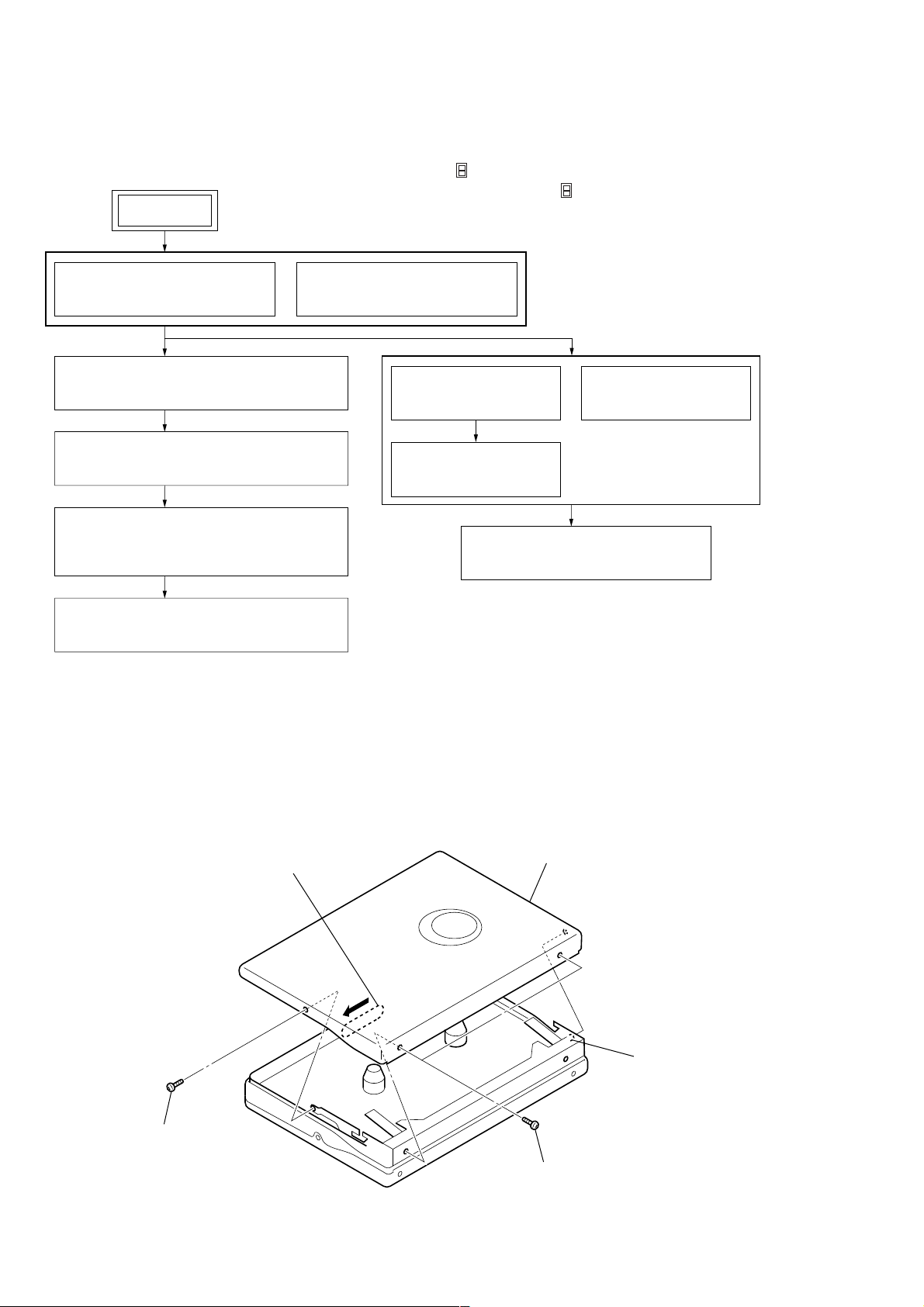
3-2. LID CASSETTE ASSY
1
Open the lid cassette assy.
2
screw
(M1.4)
4
lid cassette assy
2
two screws
(M1.4)
3
bos
6
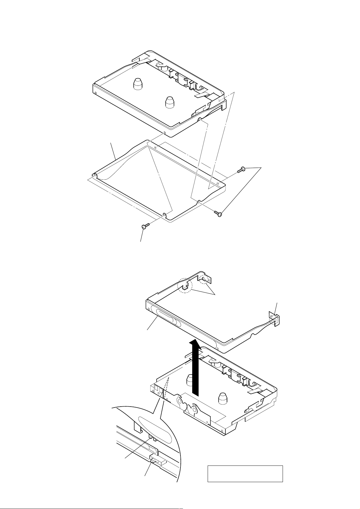
3-3. CASE BLOCK ASSY
2
case block assy
1
three screws
(M1.4
×
WM-EX526
3.0)
1
two screws
(M1.4
3-4. REEL ORNAMENT BLOCK ASSY
2
reel ornament block assy
×
3.0)
1
two claws
1
claw
knob (hold)
S707
On installation reel ornament,
adjust the S707 and knob (hold).
7
WM-EX526
)
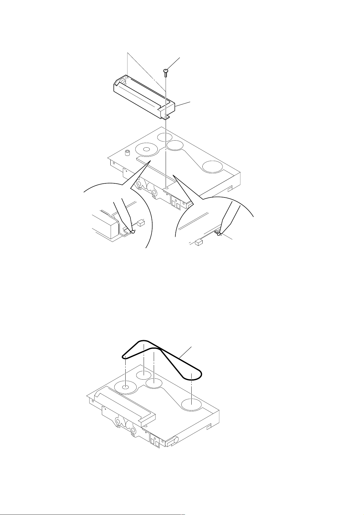
3-5. BATTERY HOLDER
2
two screws
3
battery holder
3-6. BELT (F2)
1
Break the soldering
of battery terminal (–).
1
Break the soldering
of battery terminal (+).
1
belt (F2) (See page 4
8
 Loading...