

Sony WM-EX510 Service Manual
Q
Q
3
7
6
3
1
WM-FX822
5
1
5
0
8
9
2
4
9
8
2
9
9
SERVICE MANUAL
Ver 1.1 2002. 01
TEL 13942296513 QQ 376315150 892498299
Model Name Using Similar Mechanism WM-EX510
Tape Transport Mechanism Type MT-WMEX510-112
SPECIFICATIONS
Radio section
Frequency range
TEL
Tape player section and general
Frequency response
Output
Power output
Power requirements
Battery life (Approx. hours)
Rechargeable NC-6WM
fully charged
Playback 5
Radio/TV reception 7.5
Sony alkaline LR6 (WM)
Playback 16
Radio/TV reception 24
13942296513
FM (stereo) : 76.0 - 90 MHz
AM (mono) : 531 - 1,710 kHz
TV (mono): 1 -12 ch
(a NR off)
20 - 18,000 Hz (EIAJ*)
Headphones (2/REMOTE jack)
load impedance 8 - 300 Ω
4 mW + 4 mW (EIAJ, 16 Ω)
DC1.5V
Rechargeable battery (NC-6WM)
One R6 (size AA) battery
Dimensions
Mass
7
3
Q
Q
Design and specifications subject to change without notice.
Using AC power
Remove the rechargeable battery if inserted and attach the battery
case and connect the AC power adaptor (AC-E15L or ACE15HG) not supplied) to the DC IN 1.5V of the battery case and
to the wall outlet. Do not use any other AC power adaptor.
Dolby noise reduction manufactured under licence from Dolby
Laboratories Licensing Corporation.
“DOLBY” and the double-D symbol 8 are trademarks of Dolby
Laboratories Licensing Corporation.
6
3
Tourist Model
Approx. 108.5 x 78.6 x 23.0 mm (w/h/d)
incl. projecting parts and controls (EIAJ)
Main unit Approx. 145 g
5
1
5
1
For use Appox. 240 g (incl. Stereo
earphone with remote controller,
rechargeable battery NC-6WM, tape C60HF)
0
8
9
2
4
Polarity of
the plug
9
8
2
9
TEL 13942296513 QQ 376315150 892498299
9
Sony R6P (SR)
Playback 3.5
Radio/TV reception 7
9-960-416-12
w
w
2002A1600-1
© 2002.1
w
Sony Corporation
.
Personal Audio Company
Published by Sony Engineering Corporation
xia
*(EIAJ) Electric Industries Association of Japan
o
y
u
1
6
— 1 —
— Continued on next page —
RADIO CASSETTE PLAYER
3
.
c
o
m
7
Q
Q
Receiving Stations Outside Japan
1 Press BAND•RADIO ON to turn on the radio.
2 Press ENTER. The frequency digits, “PRESET” and a preset
number flash in the display.
3 Press BAND•RADIO ON for more than 2 seconds. “AREA
1” flashes in the display.
4 While “AREA 1” is flashing, press PRESET+/– repeatedly to
select either area “USA” (USA and Canada) or “Eur”
(Europe and other countries) and then press ENTER.
5 Press ASP to store the radio stations (both AM and FM)
automatically.
TEL 13942296513 QQ 376315150 892498299
The Walkman starts searching and storing stations.
6 Press BAND•RADIO ON to select the desired band and
press PRESET+/– to select a station.
3
6
3
1
5
1
5
0
Section Title Page
SECTION 1. GENERAL .......................................... 3
SECTION 2. SERVICE NOTE ................................. 4
SECTION 3. DISASSEMBLY
3-1. Bracket assembly and Cassette Holder assembly .............. 6
3-2. Audio Board ....................................................................... 6
3-3. Tuner Board ....................................................................... 7
SECTION 4. ADJUSTMENTS
4-1. Mechanical Adjustments .................................................... 8
4-2. Electrical adjustments ........................................................ 8
SECTION 5. DIAGRAMS
5-1. Printed Wiring Board — Tuner Section —.....................11
5-2. Schematic Diagram — Tuner Section —........................ 13
5-3. Schematic Diagram — Audio Section — ....................... 17
5-4. Printed Wiring Board — Audio Section — .................... 21
5-5. IC Pin Functions
IC701 MSM63120B System Control .............................. 25
IC702 SMC62L3A LCD Driver ...................................... 26
4
2
9
8
TABLE OF CONTENTS
9
8
2
9
9
TEL 13942296513 QQ 376315150 892498299
TEL
w
w
13942296513
SAFETY-RELATED COMPONENT WARNING !!
COMPONENTS IDENTIFIED BY MARK ! OR DOTTED
LINE WITH MARK ! ON THE SCHEMATIC DIAGRAMS
AND IN THE PARTS LIST ARE CRITICAL TO SAFE
OPERATION. REPLACE THESE COMPONENTS WITH
SONY PARTS WHOSE PART NUMBERS APPEAR AS
w
.
SHOWN IN THIS MANUAL OR IN SUPPLEMENTS
xia
PUBLISHED BY SONY.
o
y
u
SECTION 6. EXPLODED VIEWS
Q
Q
6-1. Case and Tuner Board Section ........................................ 28
6-2. Audio Board Section........................................................ 29
6-3. Mechanism Section (WM-EX510-112) ........................... 30
SECTION 7. ELECTRICAL PARTS LIST ............. 31
Notes on chip component replacement
• Never reuse a disconnected chip component.
• Notice that the minus side of a tantalum capacitor may be
damaged by heat.
Flexible Circuit Board Repairing
• Keep the temperature of the soldering iron around 270 °C
during repairing.
• Do not touch the soldering iron on the same conductor of
the circuit board (within 3 times).
• Be careful not to apply force on the conductor when
soldering or unsoldering.
1
6
3
6
7
3
3
.
1
5
c
1
0
5
o
9
8
m
2
4
9
8
2
9
9
— 2 —
SECTION 1
GENERAL
7
Q
Q
TEL 13942296513 QQ 376315150 892498299
TEL
3
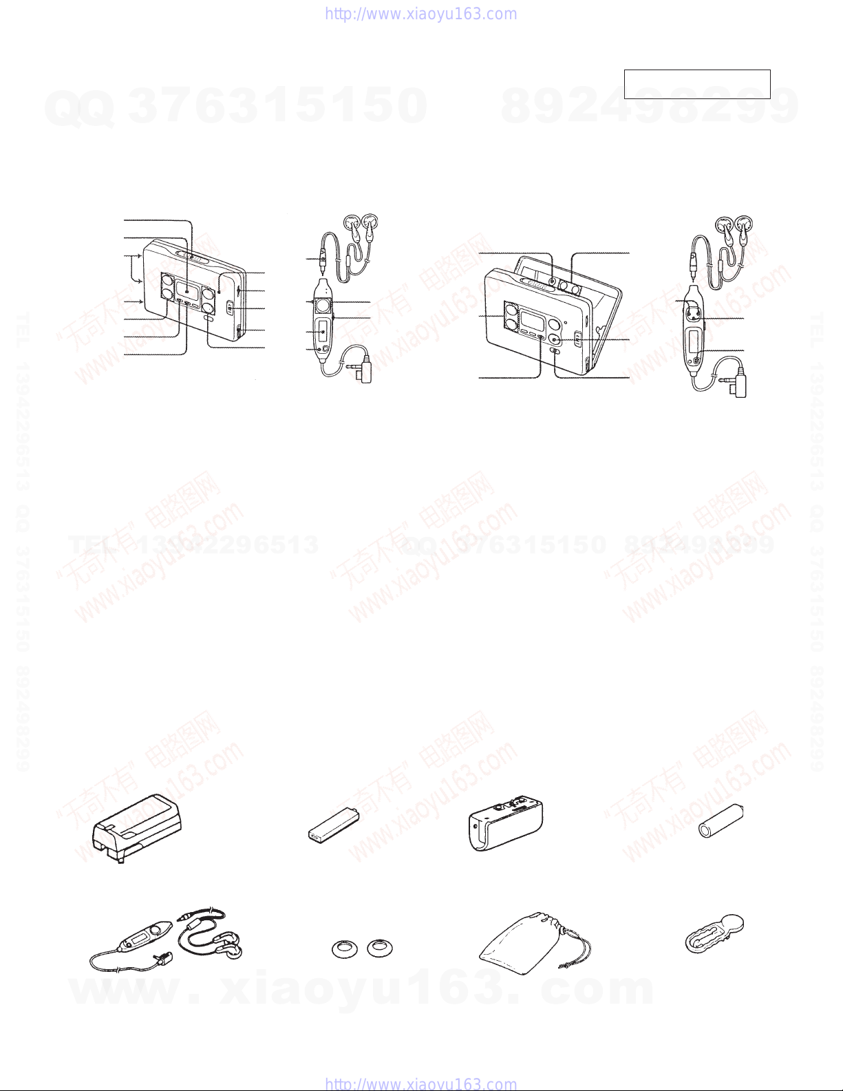
PARTS IDENTIFICATION
Tape Player and General section Radio section
1
2
3
4
5
6
7
1 OPEN knob
2 Display window
3 Terminal for a dry battery case
4 Battery compartment lid
(for the rechargeable battery)
5 Tape operation buttons
6 MENU (function select) botton
7 SET (function change) botton
8 BATT (battery) indicator
9 Main unit : VOLUME knob
0 Main unit : Hold cover
!¡ 2 REMOTE (Headphone with remote control unit)
!™ Micro plug
!£ DBB (dynamic bass boost)/ALARM botton
13942296513
Remote controller : VOL knob
Remote controller : HOLD switch
jack
6
3
1
8
9
0
!¡
!™
5
!™
9
2
!£
1
L
5
R
5
0
0
Q
Q
1
2
3
1 ENTTER (input) button
2 PRESET +, – button
3 ASP (Automatic Station Preset) button
4 TUNE (tuning) +/– switch
5 p • RADIO OFF (stop/radio off) button
6 BAND (FM/AM/TV band select) • RADIO ON
7
3
8
button
3
6
9
1
5
1
2
5
4
0
This section is extracted
from instruction manual.
2
8
9
L
4
2
5
6
2
8
9
4
2
9
8
9
R
5
6
9
9
TEL 13942296513 QQ 376315150 892498299
9
Accessories supplied
• Battery charger • Rechageable battery • Battery case • Sony alkaline battery AM3 (SR)
• Stereo earphone • Ear adaptors(2) • Carrying case • Clip
(with Remote Controller) (If the earphones do not fit your
• Plug adaptor
w
w
• Instruction manual
w
• Leaf lets
• Warranty card
.
xia
NC-6WM
ears, attach the ear adaptors.)
o
y
u
1
6
— 3 —
3
.
c
o
m
SECTION 2
SERVICE NOTE
7
Q
Q
[Service Mode]
Mode which enables the mechanism to be operated with the
MAIN board opened.
1. Setting
1) Refer to “Disassembly” and remove the cabinet and open the
MAIN board.
2) Connect the MAIN board to the motor and plunger using a
jumper wire. Use “Extension tool (1-769-143-11) (one set 10
tools)” to make connection simple.
3) Short-circuit theTP52 and GND by soldering.
TEL 13942296513 QQ 376315150 892498299
4) Turn OFF the BL SKIP switch.
5) Apply a square wave signal or a sine wave signal to TP52.
(see the right figure)
6) Supply 1.3V to the battery terminals (+) and (–) using a
stabilized power supply.
3
6
3
1
5
1
5
0
[MAIN Board]
TO
PLUNGER
8
TP50
9
BATT
FF
REW
2
50KΩ
TP52
4
AF oscillator
ND701
9
+
–
8
SQUARE
WAVE
(SINE WAVE)
10Hz, –3.5dB
2
MOTOR
BATT
TO
9
9
TEL 13942296513 QQ 376315150 892498299
2. Preset State
This state must be set to set the PLAY, FF, and REW modes.
1) Check that the lever (NR SW) is at the center and F/R switch
(S701) is at the center. If not, set the preset state as follows.
2) Move the N/R switch (S701) according to the side faced by
the lever (NR SW).
3) Turn OFF the stabilized power supply switch once and then
turn it ON again so that the lever (NR SW) can be moved.
Move the N/R switch (S701) according to this timing and set
TEL
to the center.
3. FF REW Mode
1) Check the “2. Preset State” and press the FF switch and
REW switch.
4. PLAY Mode
1) Check the “2. Preset State”.
2) Press the œ switch. The lever (NR SW) will move to the F
side once and then to the R side. Move the N/R switch
(S701) according to this timing to set the PLAY (R side)
mode. Press the œ switch another time and move the N/R
switch (S701) according to the movement of the lever (NR
SW) to set the PLAY (N side) mode.
13942296513
— Side A —
— Side B —
7
3
Q
Q
[Lever (NR SW)]
IC702
5
1
3
6
S701
N SIDE R SIDE
CENTER
1
PH701
5
0
8
9
2
4
9
8
2
9
9
Note 1: If the above cannot be performed, start again from preset.
Note 2: Use the remote control œ, p , FF, and REW switches as
much as possible. If the remote control is not available, do
not touch switch with the hand and use something with a
round tip to press them.
Note 3: By using a headphone, the timing for moving S701 can be
known by the beep.
w
w
w
.
xia
o
y
u
1
— 4 —
6
3
.
R side
Lever
(NR SW)
c
Center
o
F side
m
7
Q
Q
TEL 13942296513 QQ 376315150 892498299
3
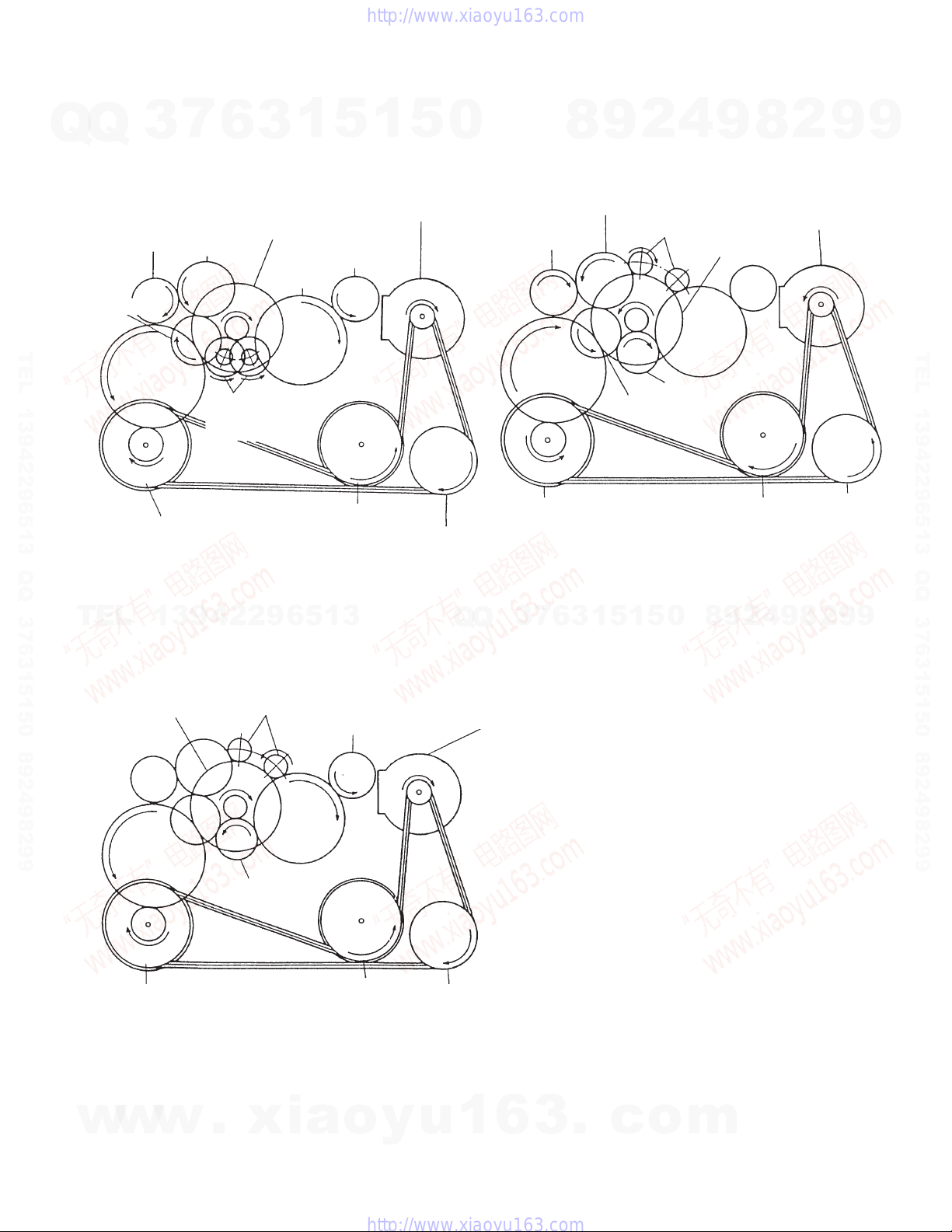
[Rotation system]
Rotation system during PLAY.
Reel table
(T side)
Gear (A)
Gear (K)
Capstan wheel (N)
assembly
6
Clutch assembly
Gear (B)
Gear (NR)
(REW : Left side/
FWD : Right side)
1
3
Reel table
(S side)
Gear (C)
Capstan wheel (R)
assembly
5
1
5
Motor pully
0
Rotation system during REW.
Reel table
(T side)
Gear (K)
Capstan wheel (N)
assembly
Pulley
(REVERSE)
8
Gear (B)
9
Gear (A)
4
2
Gear (FR)
(REW : Left side)
9
Clutch assembly
Gear (NR)
Capstan wheel (R)
assembly
8
2
9
Motor pully
Pulley
(REVERSE)
9
TEL 13942296513 QQ 376315150 892498299
TEL
Rotation system during FF.
Capstan wheel (N)
assembly
13942296513
Clutch assembly
Gear (K)
Gear (NR)
Gear (FR)
(FF : Right side)
Gear (C)
Capstan wheel (R)
assembly
Reel table
(S side)
Q
Q
Motor pully
Pulley
(REVERSE)
3
7
6
3
1
5
1
5
0
8
9
2
4
9
8
2
9
9
w
w
w
.
xia
o
y
u
1
6
— 5 —
3
.
c
o
m
SECTION 3
DISASSEMBLY
7
Q
Q
Note : Follow the disassembly procedure in the numerical order given.
3-1. BRACKET ASSEMBLY AND CASSETTE HOLDER ASSEMBLY
3
1
Screw (M1.4)
6
3
1
5
2
Bracket assembly
1
5
0
8
9
4
2
4
Lever (B), Lock
3
9
Screw
(M1.4)
8
2
9
9
TEL 13942296513 QQ 376315150 892498299
5
Screw (M1.4)
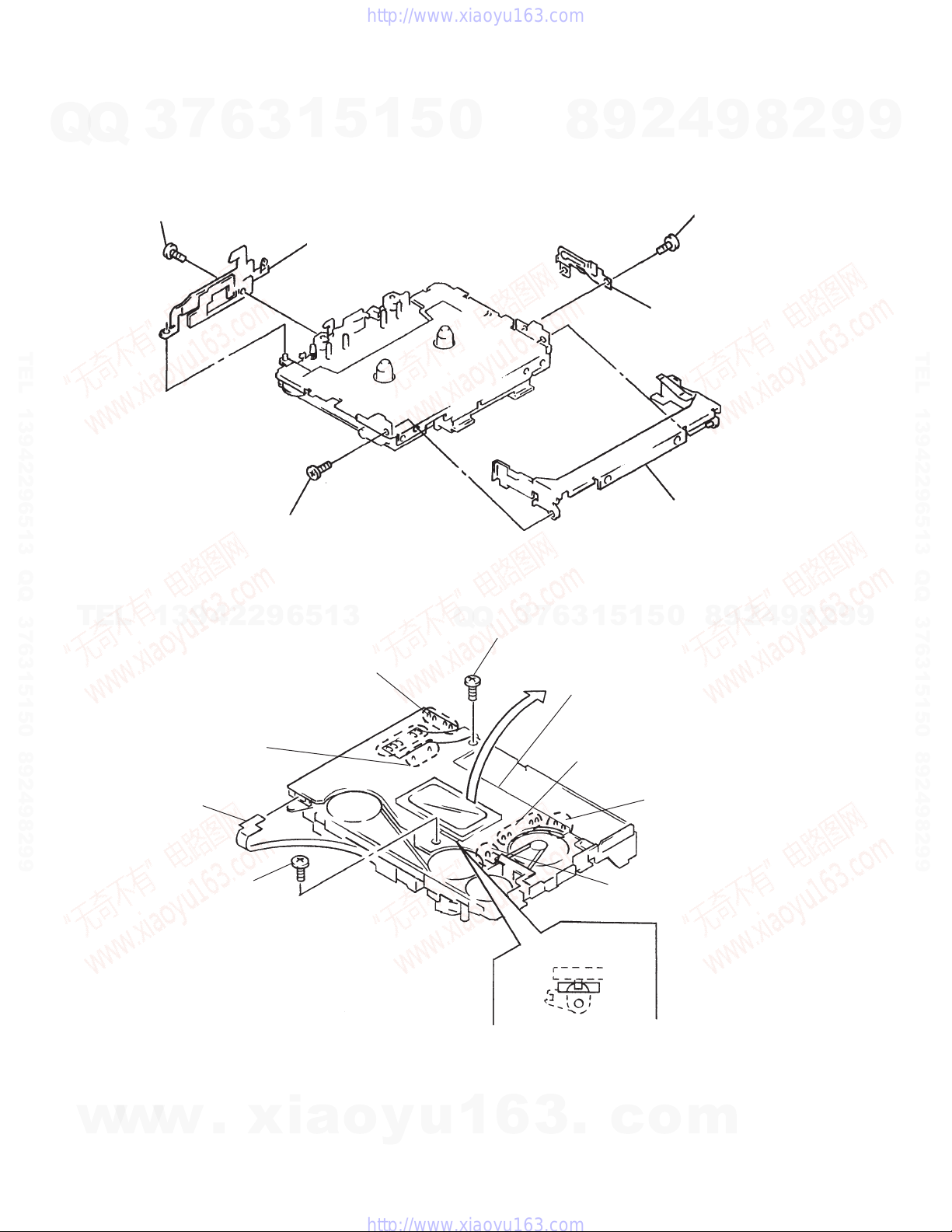
3-2. AUDIO BOARD
TEL
6
7
13942296513
4
5
Remove the solder
of the flexible board.
Remove the solder of
the plunger solenoid.
Flexible board
(Head)
Remove the solder of
the switch (S901).
Q
Q
9
7
3
Screw (M1.4)
6
Cassette holder assembly
5
1
5
1
3
6
0
Remove the Audio board
direction of arrow.
2
Remove the solder
of the motor.
3
4
2
9
8
0
Remove the solder of
the battery terminal.
9
8
2
9
TEL 13942296513 QQ 376315150 892498299
9
w
w
8
Screw (M1.4x2.0)
w
.
xia
Note: Confirm if the switch lever
o
y
u
1
6
— 6 —
1
Remove the solder of the
battery terminal.
S701
Lever (NR SW)
installs itself in the groove of
a lever (NR SW) for
assembling.
3
.
c
o
m
7
Q
Q
TEL 13942296513 QQ 376315150 892498299
3
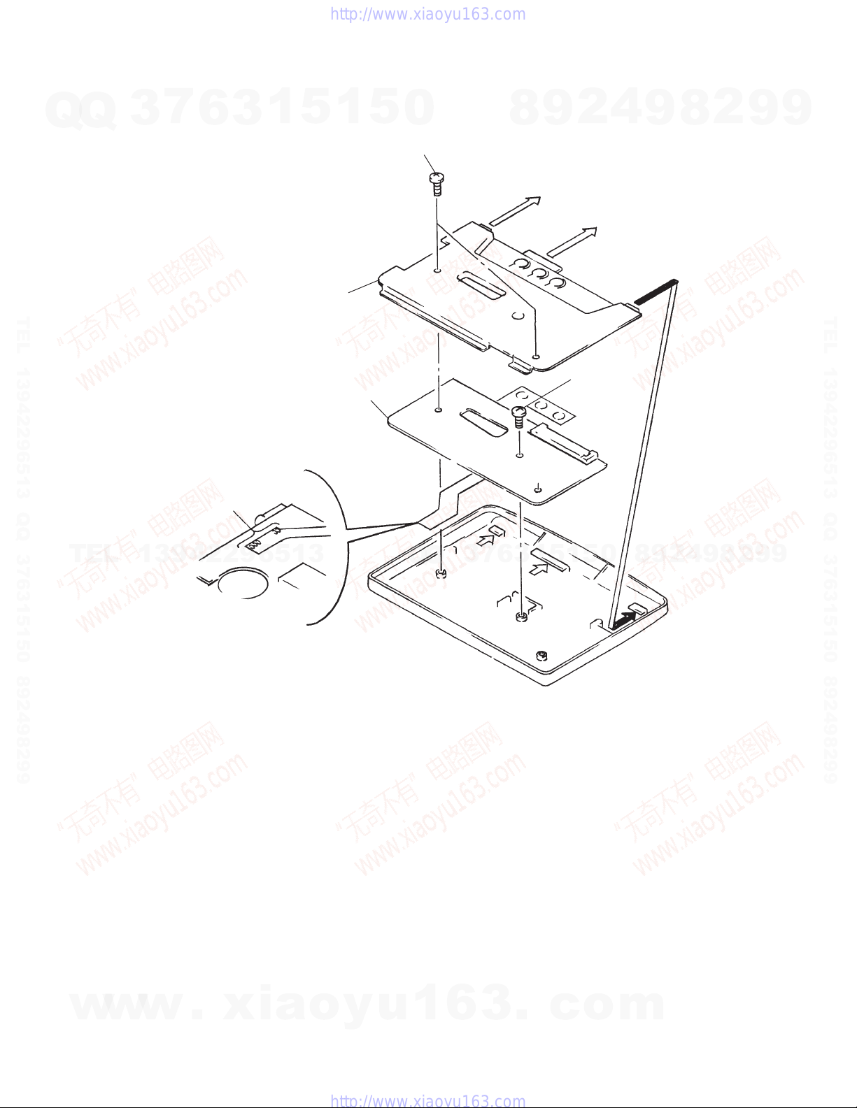
3-3. TUNER BOARD
1
Remove the solder of
the flexible board.
6
3
1
3
5
TU cover
5
1
5
Tuner board
0
2
Screw (M1.7x2.5)
8
9
2
4
Screw
(M1.7x2.5)
4
9
8
2
9
9
TEL 13942296513 QQ 376315150 892498299
TEL
13942296513
Q
Q
3
7
6
3
1
5
1
5
0
8
9
2
4
9
8
2
9
9
w
w
w
.
xia
o
y
u
1
6
— 7 —
3
.
c
o
m
SECTION 4
ADJUSTMENTS
7
Q
Q
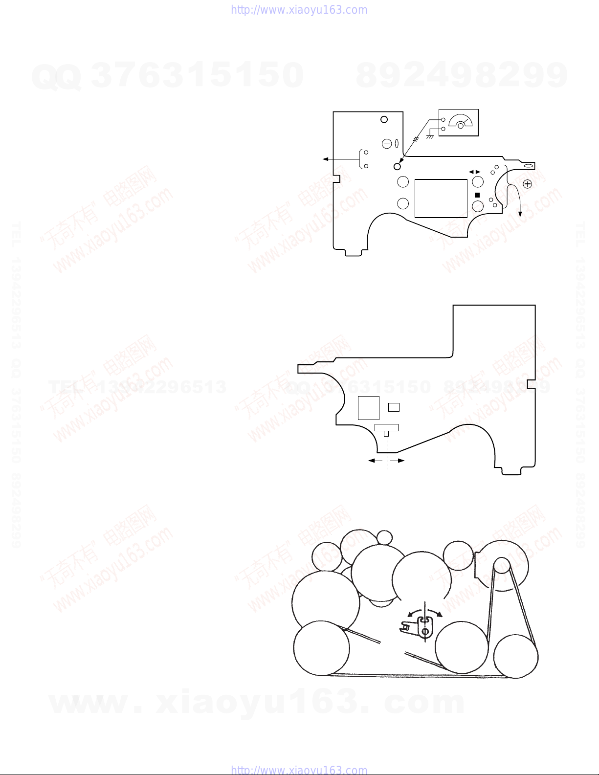
4-1. MECHANICAL ADJUSTMENTS
PRECAUTION
1. Clean the following parts with a denatured-alcohol-moistened
swab :
2. Demagnetize the playback head with a head demagnetizer.
3. Do not use a magnetized screwdriver for the adjustments.
4. After the adjustments, apply suitable locking compound to the
parts adjusted.
5. The adjustments should be performed with the rated power
TEL 13942296513 QQ 376315150 892498299
supply voltage (1.3V) unless otherwise noted.
Torque Measurement
FWD
FWD
Back Tension
REV
REV
Back Tension
3
playback head rubber belts
capstan pinch roller
Mode Torque Meter
6
CQ-102C
CQ-102RC
3
1
5
Meter Reading
18 — 33 g • cm
0.5 — 3 g • cm
18 — 33 g • cm
0.5 — 3 g • cm
1
5
0
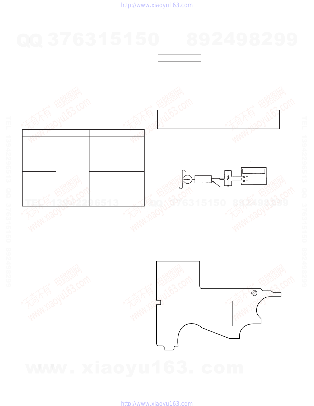
4-2. ELECTRICAL ADJUSTMENTS
TAPE SECTION
PRECAUTION
1. Power supply voltage : 1.3V.
2. Switch position
DOLBY NR switch : OFF
EX DBB switch : NORM
Test Tape
Type
WS-48A
TAPE SPEED ADJUSTMENT
Procedure :
Test Tape
WS-48A
(3kHz, 0dB)
8
2
9
Signal
3 kHz, 0 dB
set
4
Tape Speed Adjustment
16
9
Used for
frequency
counter
8
+
–
2
9
9
TEL 13942296513 QQ 376315150 892498299
FF
REW
TEL
CQ-201B
more than 60 g • cm
13942296513
REMOTE jack
1. Play back WS-48A (tape center portion) in FWD mode.
Adjust the RV601 so that the frequency counter reads 3,000 ±
Q
Q
30 Hz.
2. Play back WS-48A (tape center portion) in REV mode.
Confirm that the reading of frequency counter is within 2.5%
from the reading in step 1.
Adjustment Part Location Diagram :
[MAIN BOARD] (SIDE A)
3
7
6
3
1
5
1
ND701
5
0
8
9
RV601
2
4
9
8
2
9
9
w
w
w
.
xia
o
y
u
1
6
— 8 —
3
.
c
o
m
7
Q
Q
TEL 13942296513 QQ 376315150 892498299
3
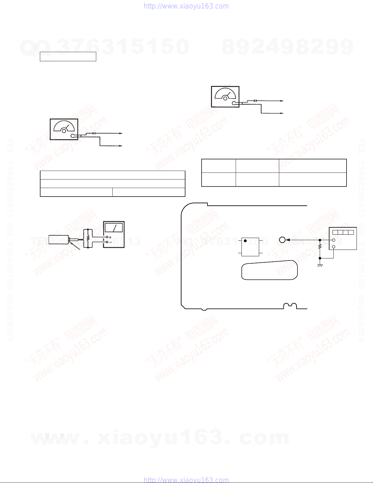
TUNER SECTION
FM SECTION
Setting:
FUNCTION switch : RADIO
BAND switch : FM
FM RF SSG
Modulation : 400 Hz, 22.5 kHz dev. (30%)
Output level: as low as possible.
6
0.01µF
FM IF ADJUSTMENT
Adjust for a maximum reading on VTVM.
L5 76.00 MHz
(AC : 0.5–5V range)
16
3
VTVM
1
TP (ANT)
TP (GND)
5
1
5
0
VCO ADJUSTMENT
Carrier frequency : 78.00 MHz
Modulation : no-modulation
Output level : 55 dB (562 µV)
[TUNER BOARD]
Adjustment
Element
8
FM RF SSG
RV1
4
2
9
0.01µF
Frequency
Display
78.00 MHz 19.00 kHz ± 0.05 kHz
9
TP (ANT)
TP (GND)
Frequency counter
8
Reading
2
9
frequency
counter
9
TEL 13942296513 QQ 376315150 892498299
TEL
set
13942296513
REMOTE jack
Q
Q
3
7
6
3
1
5
1
IC3
5
0
9
8
TP
(VCO)
2
4
150kΩ
9
8
2
9
+
9
–
w
w
w
.
xia
o
y
u
1
6
— 9 —
3
.
c
o
m
 Loading...