

Sony Wega KE-MR50, Wega KE-MR61, Wega KLV-MR32 Operating Instructions Manual
2-187-711-11 (3)
Plasma TV/LCD TV
Plasma TV
LCD TV
KE-MR50/KE-MR61/KLV-MR32
Operating Instructions
• Before operating the unit, please read this manual thoroughly and retain it
for future reference.
KE-MR50
KE-MR61
KLV-MR32
© 2004 Sony Corporation
A2
S2
Safety Information
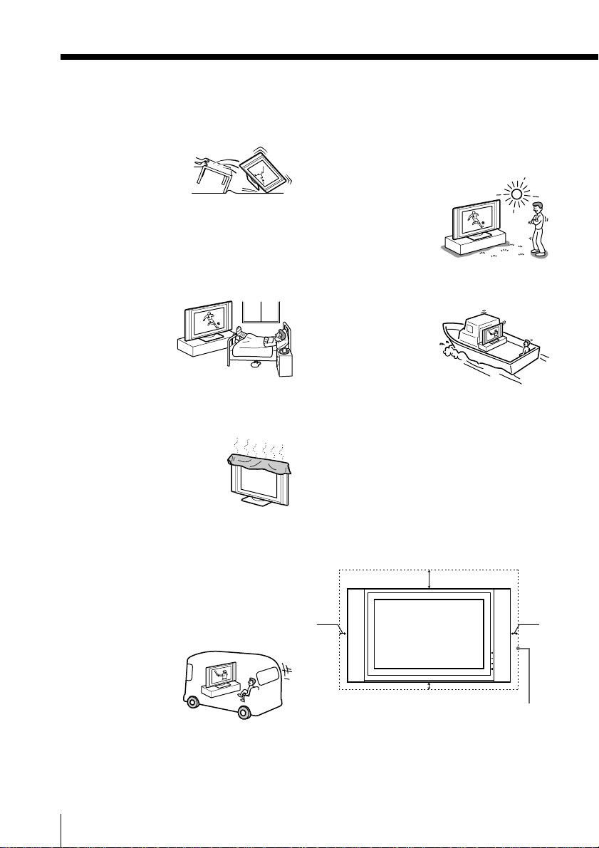
For Safety
AC power cord and display cable
Unplug the AC power
cord and display cable
when moving the TV set.
Do not move the TV set
with the AC power cord
and display cable
plugged in. It may damage the AC power cord
and display cable and result in fire or electric
shock. If the TV set has been dropped or
damaged, have it checked immediately by
qualified service personnel.
Medical institution
Do not place this TV
set in a place where
medical equipment is
in use. It may cause
malfunction of
medical instruments.
Installation and moving
Ventilation
Never cover the ventilation holes
in the cabinet. It may cause
overheating and result in fire.
Unless proper ventilation is
provided, the TV set may gather
dust and get dirty. For proper
ventilation, observe the following:
• Do not install the TV set turned backward or
sideways.
• Do not install the TV set turned over or
upside down.
• Do not install the TV set on a shelf or in a
closet.
• Do not place the TV set on a rug or bed.
• Do not cover the TV set with cloth, such as
curtains, or items such as newspapers, etc.
Vehicle and ceiling
Do not install this TV set
in a vehicle or hang it
from the ceiling.
Bumping of the vehicle
may cause the TV set to
fall down and cause
injury.
Water and moisture
Do not use this TV set near water - for example,
near a bathtub or shower room. Also do not
expose to rain. It may result in fire or electric
shock.
Outdoor use
Do not install this TV set
outdoors. If the TV set is
exposed to rain, it may
result in fire or electric
shock. If the TV set is
exposed to direct
sunlight, the TV set may
heat up and it may
damage the TV set.
Ship and vessel
Do not install this TV set
in a ship or vessel. If the
TV set is exposed to
seawater, it may cause
fire or damage the TV
set.
Cord arrangement
Arrange the power cords or connecting cords in
a safe place to avoid tripping on them.
Ventilation
Leave space around the display unit and media
receiver unit. Otherwise, adequate air-circulation
may be blocked causing overheating and cause
fire or damage the TV set.
When installing the display unit
on the wall
30cm
10cm10cm
10cm
Leave this space at least.
2
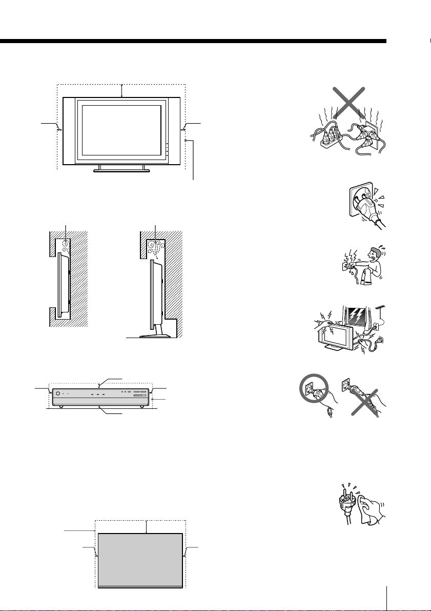
When installing the display unit
using a stand
30cm
10cm
10cm
Leave this space at least.
Never install the display unit as follows:
Air circulation
is blocked.
Wall
Air circulation
is blocked.
Wall
For the media receiver unit
Media receiver box: Front view
5cm
Place the media receiver unit on a stable level
surface so as not to block the inlets at the bottom
of the media receiver unit.
Media receiver box: Top view
Never place the media receiver unit in a
confined space. It may cause overheating and
result in fire or damage the unit.
To ensure reliable operation of the unit leave
enough space for ventilation by the exhaust fan.
Leave
this
space at
least.
7cm
5cm
Leave
this
0.5cm
5cm 5cm
space at
least.
10cm
Power Sources
Overloading
This TV set is designed
to operate on a 220-240V
AC supply. Take care not
to connect too many
appliances to the same
AC power socket as this
could result in fire or
electric shock.
AC power outlet
Do not use a poor fitting AC power
socket. Insert the plug fully into the
AC power outlet. If it is loose, it may
cause arcing and result in fire.
Contact your electrician to have the
AC power socket changed.
Moisture
Do not touch the AC power cord
with a wet hand. If you plug/
unplug the AC power cord with a
wet hand, it may cause electric
shock.
Lightning storms
For your own safety, do
not touch any part of the
TV set, AC power cord or
antenna lead during
lightning storms.
AC power cord protection
Pull out the AC power
cord by the plug. Do
not pull on the AC
power cord itself.
Wiring
Unplug the AC power cord when wiring cables.
Be sure to unplug the AC power cord for your
safety, when hooking up.
Cleaning
Clean the AC power plug
regularly. If the plug is covered
with dust and it picks up
moisture, its insulation may
deteriorate and result in fire.
Unplug the AC power plug and
clean it regularly.
3

Grounding
To avoid electric shock, be sure to connect the
supplied AC power cord to a grounded power
outlet.
If the plug fails to fit, contact your electorican to
have the outlet changed.
Use
Damage requiring service
If the surface of the display unit cracks, do not
touch it until you unplug the AC power cord.
Otherwise electric shock may result.
Servicing
Do not open the cabinet
and the rear cover of
the TV set. Refer to
qualified service
personnel only.
Ventilation holes
Do not insert anything in the
ventilation holes. If metal or
something flammable enters, it
may result in fire or electric
shock.
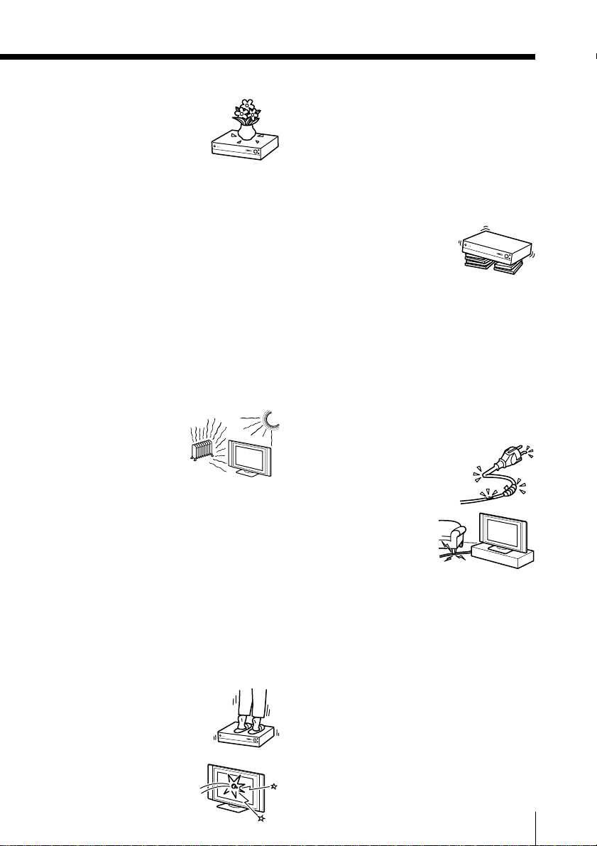
Moisture and flammable
• Do not let this TV set get
wet. Never spill liquid of
any kind on the set. If any
liquid or solid object does
fall through, do not operate
the TV set. It may result in electric shock or
damage to the TV set. Have it checked
immediately by qualified personnel.
•To prevent fire, keep inflammable objects or
naked lights (e.g. candles) away from the TV
set.
• Do not place any objects
on the unit.
The apparatus shall not
be exposed to dripping
or splashing and that no
objects filled with
liquids, such as vases,
shall be placed on the
apparatus.
For the display unit
Installation
Installation of the
display unit on the wall
should be carried out by
qualified servicemen.
Improper installation
may render the display
unit unsafe.
Carrying
Carrying the display unit
requires two or more people.
If you carry the display unit
in a manner other than that
specified, it may drop and a
serious injury may be
caused. Be sure two or more people carry the
display unit. When transporting, do not subject
the display unit to shocks or excessive vibration.
The display unit may fall and be damaged or
cause serious injury.
Optional accessories
Observe the following when
installing the display unit using a
stand or wall-mount bracket. If not,
the display unit may fall and cause
serious injury.
• Be sure to follow the operating instructions
supplied with your stand when installing the
display unit.
• Be sure to attach the brackets supplied with
your stand.
Fall
Place the display unit on a secure,
stable stand. Do not hang
anything on the display unit. The
display unit may fall from the
stand or wall-hanging rack unit,
causing damage or serious injury.
For the media receiver unit
Object placement
Do not place anything heavy
on the media receiver unit. It
may damage the unit.
4
Liquid placement
Do not place objects containing
liquid on the media receiver unit.
It may result in electric shock or
damage the media receiver unit.
Additional Safety
Information
Electric shock
Do not touch the TV set with a wet hand. Doing
so may cause electric shock or damage the TV
set.
Protruding location
Do not install the display unit in protruding
locations. If you install the display unit in the
following locations, injury may result.
• Do not install the display unit in a location
where the display unit protrudes, such as
pillars.
• Do not install the display unit in a location
where your face may bump.
Placement
Never place the TV set in
hot, humid or excessively
dusty places. Do not install
the TV set where it may be
exposed to mechanical
vibrations.
Oils
Do not install this TV set in restaurants that use
oil. Dust absorbing oil may enter into the TV set
and damage the TV set.
Accessories
Secure the display unit from falling down.
If the display unit is not secured properly, it may
fall and cause injury. Take measures against it
using a stand or other apparatus on the floor or
wall in the specified manner, referring to the
operating instructions supplied with your stand
or wall-mount bracket.
Weight
Do not stand on the media
receiver unit. The media receiver
unit may fall or be broken,
causing injury. Pay special
attention to little children.
Broken pieces
Do not throw anything at the
display unit. The screen glass
may explode by the impact
and cause serious injury.
Corrosion
If you use this TV set near the seashore, salt may
corrode metal parts of the TV set and cause
internal damage or fire. It may also shorten the
life of the TV set. If the TV set will be subjected
to none of these conditions, steps should be
taken to reduce the humidity and temperature of
the area where the TV set is located.
Recommended place for the
media receiver unit
Place the media receiver unit on
a stable, level surface.
Otherwise, the media receiver
unit may fall and cause injury.
Cleaning
Unplug the AC power cord when cleaning this
TV set. If not, it may result in electric shock.
Keep the connector cap for
display interface cable away from
children
A child is likely to choke on it, if swallowed. In
the event of choking, seek immediate medical
attention.
AC power cord and display cable
If you damage the AC power
cord and display cable, it may
result in fire or electric shock.
• Do not pinch, bend, or twist
the cable excessively. The
core lines may be bared
and cut, and cause shortcircuit, resulting in fire
or electric shock.
• Do not convert or
damage the AC power
cord and display cable.
• Do not put anything heavy on the AC power
cord and display cable. Do not pull the AC
power cord and display cable.
• Keep the AC power cord and display cable
away from heat sources.
• Be sure to grasp the plug when disconnecting
the AC power cord and display cable.
Refer to the operating instructions when
disconnecting the display cable.
If the AC power cord and display cable are
damaged, stop using it and ask your dealer or
Sony service center to exchange it.
5
Not in use
For environmental and
safety reasons, it is
recommended that the
TV set is not left in
standby mode when
not in use. Disconnect
from the AC power outlet.
Cable wiring
Take care not to catch your feet on the cables. It
may damage the TV set.
Installation
Do not install optional components too close to
the display unit. Keep optional components at
least 30 cm away from the display unit. If a VCR
is installed in front or at the side of the display
unit, the picture may distort.
Heat
Do not touch the surface of the display unit. It
remains hot, even for some time after the display
unit is turned off.
Disposal of the unit (KLV-MR32
only)
• Do not dispose of the unit with general
household waste.
• The LCD contains a small amount of liquid
crystal and mercury. The fluorescent tube
used in this unit also contains mercury. Follow
your local ordinances and regulations for
disposal.
Precautions
On viewing the TV comfortably
•To view the TV comfortably, the recommended viewing position is from four to
seven times of the screen’s vertical length
away from the TV set.
•View the TV in a moderate light room, as
viewing the TV in poor light taxes your eyes.
And watching the screen continuously long
times taxes your eyes, too.
On installing the TV set
Installing the display unit
Use the specified wall-mount bracket or stands.
Leave enough space for ventilation between the
exhaust fan in the rear of unit and the wall.
• Do not install the display unit in places
subject to extreme temperature, for example in
direct sunlight, or near a radiator, or heating
vent. If the display unit is exposed to extreme
temperature, the display unit may heat up
and it may cause deformations of the casing
or malfunctions.
• Do not install the display unit in a place
exposed to direct air conditioning. If the
display unit is installed in such a location,
moisture may condense on the panel inside
the display unit. It may cause a malfunction.
• After transporting the display unit directly
from a cold to a warm location, or if the room
temperature has changed suddenly, pictures
may be blurred or show poor color over
portions of the picture. This is because
moisture has condensed on the panel inside
the display unit. Let the moisture evaporate
before using the display unit.
•To obtain a clear picture, do not expose the
screen to direct illumination or direct sunlight.
If possible, use spot lighting direct down from
the ceiling.
Installing the media receiver unit
The TV set is not disconnected from AC power
outlet when the switch is in off position. To
disconnect the TV set completely, pull the plug
from AC power outlet.
On adjustment volume
• Adjust the volume so as not to trouble
neighbors. Sound carries very easily at night
time. Therefore, closing the windows or using
headphones is suggested.
• When using headphones, adjust the volume
so as to avoid excessive levels, as hearing
damage may result.
6

On handling the remote control
• Handle the remote control with care. Do not
drop or step on it, or spill liquid of any kind.
• Do not place the remote control in a location
near heat source, or in a place subject to direct
sunlight, or in a damp room.
On handling and cleaning the screen
surface of the Plasma TV
To avoid screen degradation, follow the points
mentioned below. Do not push on or scratch
with hard objects, or throw anything at the
screen. The screen may be damaged.
• Be sure to unplug the AC power cord
connected to the TV set from the AC power
outlet before cleaning.
• Do not touch the display panel after operating
continuously for a long period as the display
panel becomes hot.
•We recommend that the screen surface is
touched as little as possible.
• Clean the screen with the supplied cleaning
cloth or a soft cloth lightly moistened with a
mild detergent solution.
• Never use any type of abrasive pad, scouring
powder, or solvent, such as alcohol or
benzine. This type of contact may result in
damage to the screen surface.
On cleaning the cabinet
• Be sure to unplug the AC power cord
connected to the TV set from the AC power
outlet before cleaning.
• Clean the cabinet with the supplied cleaning
cloth or a soft cloth lightly moistened with a
mild detergent solution.
• Note that material deterioration or screen
coating degradation may occur if the display
unit is exposed to a volatile solvent, such as
alcohol, thinner, benzine or insecticide, or if
prolonged contact is maintained with rubber
or vinyl materials.
• The ventilation holes can accumulate dust
over a period of time. The accumulate dust
may make the cooling function of the built-in
fan less effective. To prevent this, we
recommended removing the dust periodically
(once a month) using a vacuum cleaner.
On the PDP (Plasma Display
Panel): only KE-MR50 and KEMR61 models
On the PDP
• Please note that the PDP screen is made with
high-precision technology. However, black
points or bright points of light (red, blue, or
green) may appear constantly on the PDP
screen, and irregular colored stripes or
brightness may appear on the PDP screen.
This is not a malfunction.
On image retention
• If the following images are displayed for an
extended period time, image retention
(afterimage) in areas of the screen may result
due to the characteristics of the Plasma
Display Panel.
– Black bars at the top and bottom that
appear with a wide video source (Letterbox
picture).
– Black bars to the left and right that appear
with a 4:3 video source (conventional TV
broadcasts).
–Video game sources
– PC images
– DVD on-screen menu displays
– On-screen menus, channel numbers, etc., of
connected equipment such as Set top box,
Cable modem, VCR, etc.
The risk of this is higher if the set is in
“Dynamic” mode or has a high contrast
setting. This image cannot be removed once
burnt onto the screen. To avoid the risk of
occurrence do not leave the TV set operating
on such a picture, or program for a long time,
use the “Screen Saver” function or lower the
contrast setting. Repeated extended daily
usage of the same image, or program can
also result in this occurrence. IMAGE
RETENTION IS NOT COVERED BY THE
SONY WARRANTY.
•To reduce image retention, this Plasma TV has
the “Screen Saver” function. The default
setting of the “Orbit” function in “Screen
Saver” is “On”.
On the LCD (Liquid Crystal
Display): only KLV-MR32 model
On the screen
• Although the LCD screen is made with highprecision technology and has effective pixels
of 99.99% or more, black dots may appear or
bright points of light (red, blue or green) may
appear constantly on the LCD screen. This is a
structural property of the LCD panel and is
not a malfunction.
7
• Do not expose the LCD screen surface to the
sun. Doing so may damage the screen surface.
• Do not push or scratch the front filter, or place
objects on top of this unit. The image may be
uneven or the LCD panel may be damaged.
• If this unit is used in a cold place, a smear
may occur in the picture or the picture may
become dark. This does not indicate a failure.
These phenomena improve as the temperature
rises.
• Ghosting may occur when still pictures are
displayed continuously. It may disappear after
a few moments.
• The screen and cabinet get warm when this
unit is in use. This is not a malfunction.
Fluorescent lamp
• This unit uses a special fluorescent lamp as its
light source. If the screen image becomes dark,
flickers, or does not appear, the fluorescent
lamp has run down and should be replaced.
For replacement, consult qualified service
personnel.
The illustrations used in this manual are of the
KE-MR50 unless otherwise stated.
8

Table of Contents
Safety Information
Precautions
Using Your New TV
Getting Started ............................................................................................ 10
Step 1 Connecting the display unit to the media receiver unit ....... 10
Step 2 Connect the antenna .................................................................. 14
Step 3 Insert the batteries into the remote .......................................... 16
Step 4 Set up your TV automatically .................................................. 17
Connecting optional components ............................................................ 19
Watching the TV ......................................................................................... 27
Using Your New TV
Advanced Operations
Selecting the picture and sound
modes................................................ 29
Viewing higher quality pictures ........ 30
Customizing the picture Reality and
Clarity levels .................................... 31
Using wide screen mode .................... 33
Listening with surround sound ......... 37
Enjoying stereo or bilingual
programs .......................................... 38
Viewing Teletext ................................... 40
Operating optional components ........ 42
Using the TV’s center speaker ........... 45
Using the picture freeze feature......... 46
Viewing the twin picture .................... 47
Using the ”Memory Stick”
viewer ............................................... 49
Adjusting Your Setup (MENU)
Introducing the menu system ............ 76
Changing the “Picture” setting .......... 81
Changing the “Sound” setting ........... 84
Entering the “Memory Stick”
menu ................................................. 87
Changing the “Wide Screen”
setting ............................................... 88
Changing the “Twin Picture”
setting ............................................... 90
Changing the “Timers” setting .......... 91
Changing the “Features” setting ....... 92
Changing the “Setup” setting ............ 95
Additional Information
Troubleshooting ................................. 108
Self-diagnosis function...................... 114
Identifying parts and controls ......... 115
Specifications ...................................... 123
Table of Contents
9
Using Y our New TV
Getting Started
Step 1
Connecting the display unit to the media receiver unit
Notes
• Use the supplied display interface cable.
• Use the supplied AC power cord for the display unit.
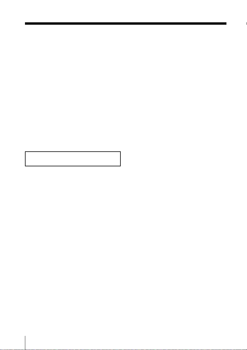
1 Connect the supplied display interface cable and the supplied AC
power cord for the display unit to the display unit.
KE-MR50/61
Using Your New TV
10
SONY EXCLUSIVE CABLE ONLY
BLACK
DISPLAY SIGNAL IN
WHITE
AC IN
KLV-MR32
SONY EXCLUSIVE CABLE ONLY
WHITE
DISPLAY SIGNAL IN
BLACK
AC IN
Note
• Do not connect the power cord until all other connections are complete;
otherwise, a minimal current leakage through the antenna and/or other
terminals to the ground could occur.
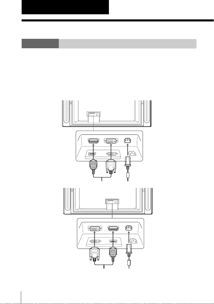
2 Secure the AC power plug to the display’s AC IN jack. (KE-
MR50/61 only)
AC IN (Power supply input)
jack of the display unit
AC power
cord
(supplied)
AC power plug
holder
(supplied)
Using Your New TV
a Attach the AC power plug
holder (supplied) to the AC
power cord.
b Clip on the AC IN jack until
you hear clicking.
Tip
•To unplug the AC power cord, pull down the AC power plug holder by
pushing in both sides of the holder, then pull out the plug.
3 Install the display unit using the specified wall-mount bracket or
stand.
Note
• Before installing the display unit, check the installation instructions of
your wall-mount bracket or stand.
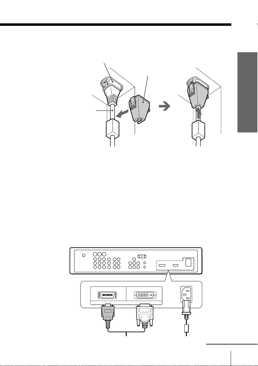
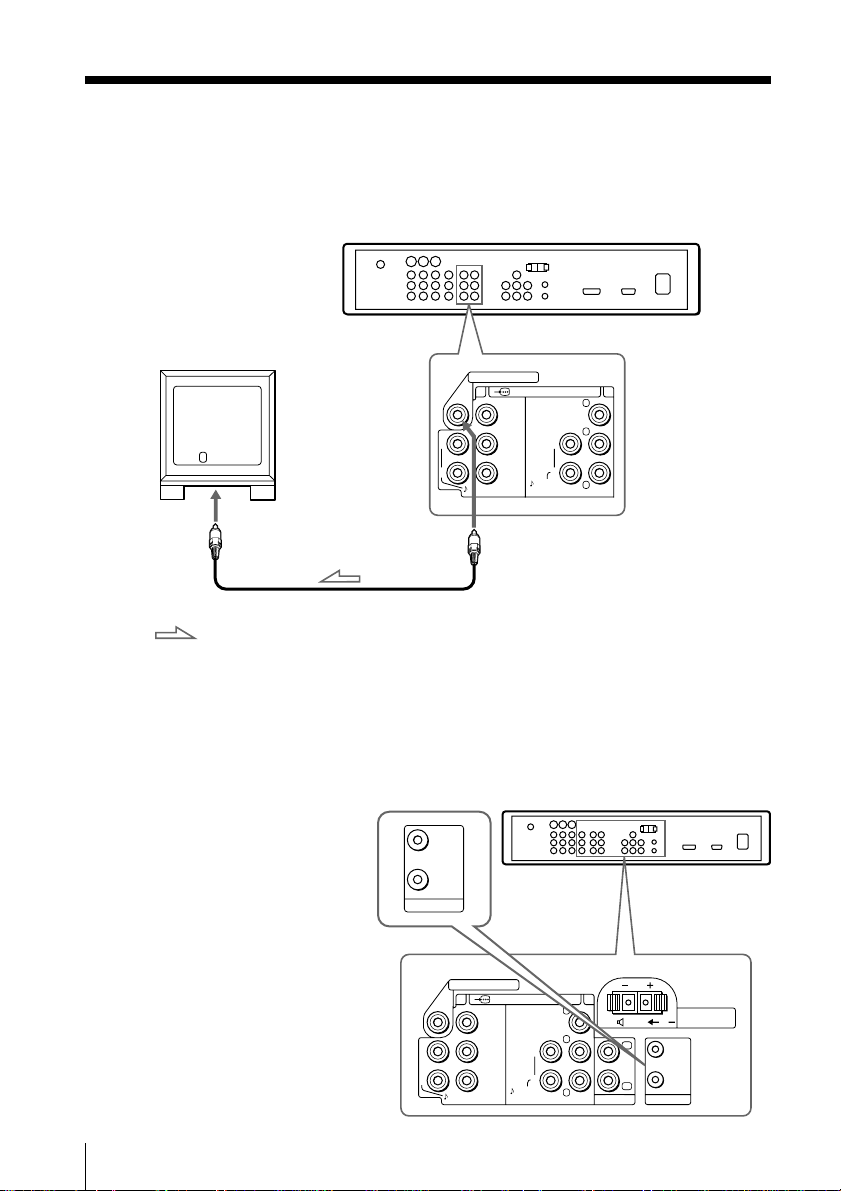
4 Connect the supplied display interface cable to the media receiver
unit.
BLACK
DISPLAY SIGNAL OUT
WHITE
AC IN
continued
Using Your New TV
11
Getting Started (continued)
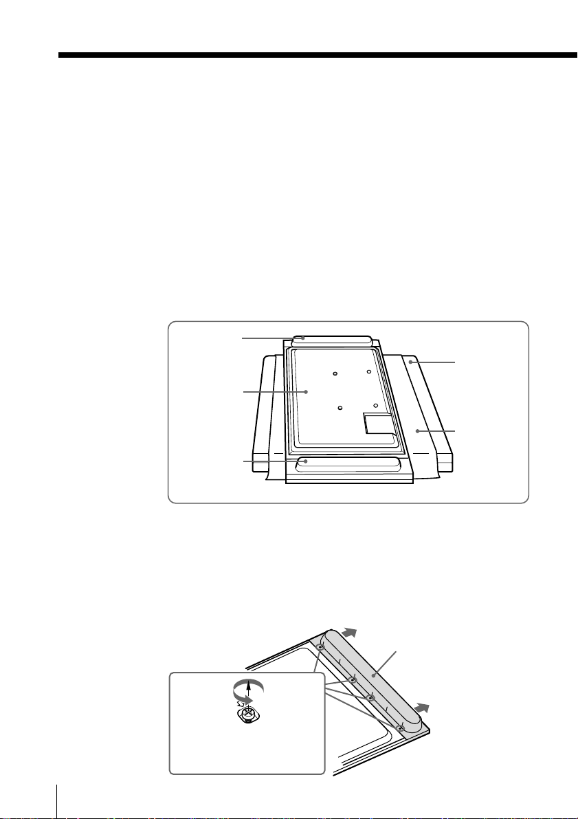
Detaching the speakers (KE-MR61 only)
Tip
• The speakers on the KE-MR61 model can be detached and the display unit
can be used with an AV receiver and speaker system connected to the T
VIDEO OUT.
Notes
• Be sure to remove the speakers before installing the display unit on a wall,
etc. Detaching the speakers from the display unit should be performed by
qualified Sony personnel.
• If the weight of the display unit is applied to the speakers when detaching
them, the speakers may be deformed or a bad contact of the speaker
terminals on the display unit may be caused. To avoid this, put the
cushions, etc. contained in the packing materials between the display unit
and the floor. Be sure to place them so that the display unit is stable on the
floor.
Speaker
(left)
Rear side of
the display
unit
Speaker
(right)
Packing
material, etc.
Padding, etc.
Using Your New TV
12
•To prevent the surface of the display unit from being scratched or soiled,
protect it with a soft cloth or similar.
1 Place a protective sheet or cloth beneath the display unit on a flat
floor. Turn the display unit over so that you can see its rear panel.
2 Remove the four screws marked with arrows on the inside of the
rear of the speaker, then pull out the speaker straight to detach.
Speaker
M4 × 10 (supplied)
Tip
• Keep the screws for future use. Use them to secure the speakers to the
display unit again.
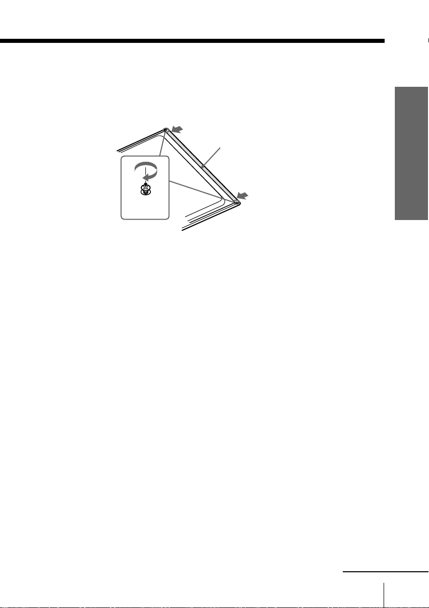
3 Attach the supplied frame bar and tighten with the supplied two
screws.
Frame bar
(supplied)
Screws
(supplied)
4 Repeat steps 2 and 3 for the other speaker.
Tip
• Do not connect the detached speakers to other audio equipment.
Using Your New TV
continued
Using Your New TV
13
Getting Started (continued)
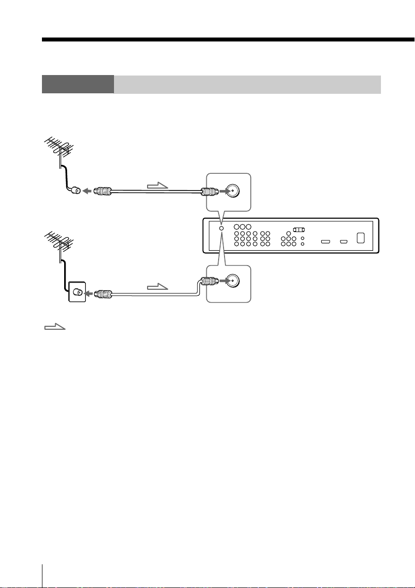
Step 2
Connect the antenna
If you wish to connect a VCR, see the “Connect a VCR” diagram on page 15.
or
: Signal flow
To 8 VHF/UHF (
Antenna cable (supplied)
Antenna cable (supplied)
8
8
VHF/UHF
VHF/UHF
antenna
)
Rear of Media Receiver Unit
To 8 VHF/UHF (
antenna
)
For optimum Performance
To connect the media receiver unit to the antenna or the VCR, use
an antenna cable (supplied).
Note that one end of the cable has a male plug fitted while the other
end is fitted with a female socket. Connect the male plug to the 8
VHF/UHF (antenna) terminal of the media receiver unit.
CAUTION
Do not connect the power cord until all other connections are complete;
otherwise, a minimal current leakage through the antenna and/or other
terminals to the ground could occur.
14
Using Your New TV

Connect a VCR
To play a video tape, press T (see page 28).
VIDEO IN
VIDEO OUT
To video and
audio outputs
: Signal flow
To 8 VHF/UHF (
Antenna cable
(supplied)
antenna
)
8
VHF/UHF
Rear of Media Receiver Unit
S video cable
(not supplied)
To antenna
output
VCR
AUDIO
R L
VIDEO
To S VIDEO
(S video input)
1, 2 or 3
To S video
output
To t VIDEO IN (video input) 1, 2 or 3
VIDEO (yellow)
S VIDEO
VIDEO
(
MONO
AUDIO
VIDEO IN
L
)
R
123
AUDIO-L (MONO) (white)
AUDIO-R (red)
Audio/Video cable
(not supplied)
Notes
• If you connect a monaural VCR, connect the yellow plug to VIDEO
(the yellow jack) and the black plug to AUDIO-L (MONO) (the white
jack).
• If you connect a VCR to the 8 VHF/UHF (antenna) terminal, preset the
signal output from the VCR to the program number 0 on the TV.
• When you connect a VCR to the S video input, display the “Setup” menu
and select “Auto” for “S Input” (see page 96). If the signals are input to
both S VIDEO (S video input) and VIDEO (video input), the S
video signal is automatically selected. To view the video signal input to
VIDEO (video input), select “Off” for “S Input”.
Using Your New TV
continued
Using Your New TV
15
Getting Started (continued)
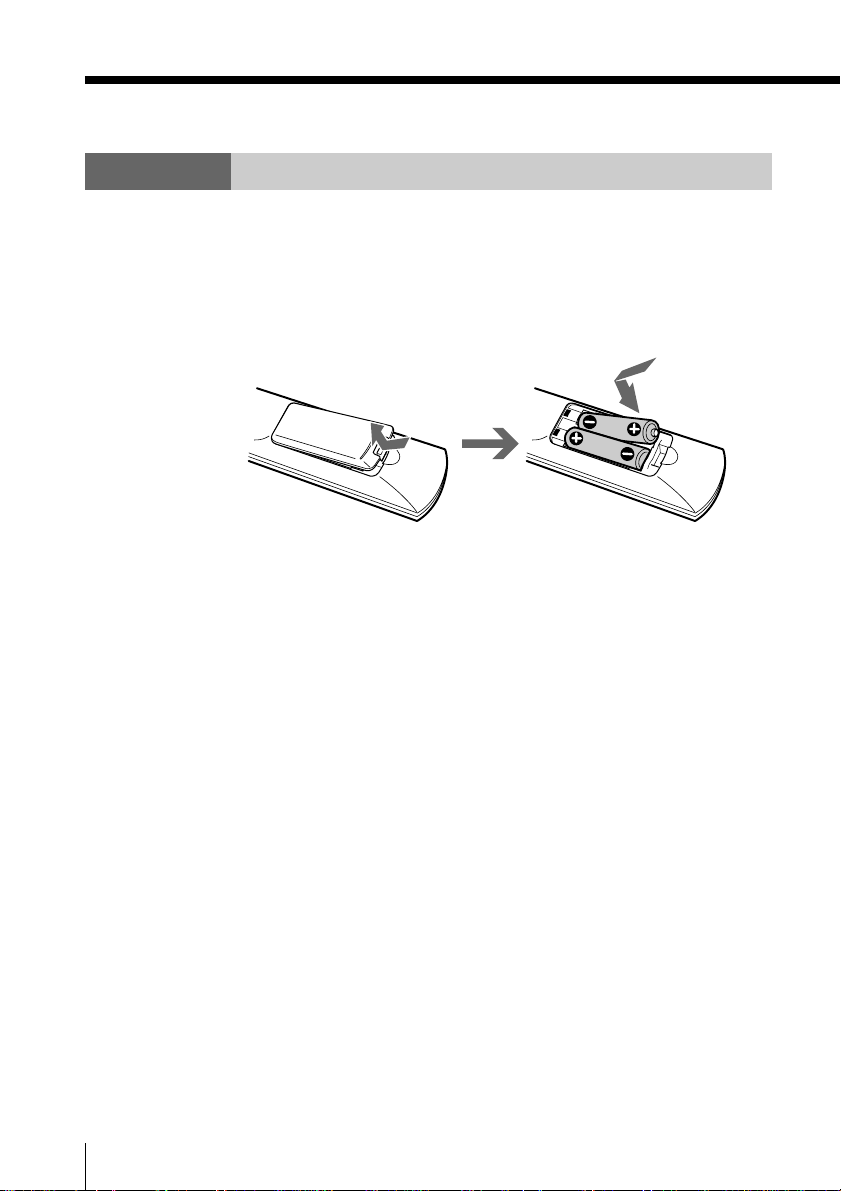
Step 3
Insert the batteries into the remote
1 Open the battery compartment as illustrated below.
2 Insert two size AA batteries (supplied) by matching the e and E
terminals on the batteries to the diagram inside the battery
compartment.
3 Close the battery compartment.
Notes
• Do not use old batteries or different types of batteries together.
• Remove the batteries to avoid damage from possible battery leakage
whenever you anticipate that the remote control will not be used for an
extended period.
• Handle the remote control with care.
•Avoid dropping it, getting it wet, placing it in direct sunlight, near a
heater, or where the humidity is high.
16
Using Your New TV
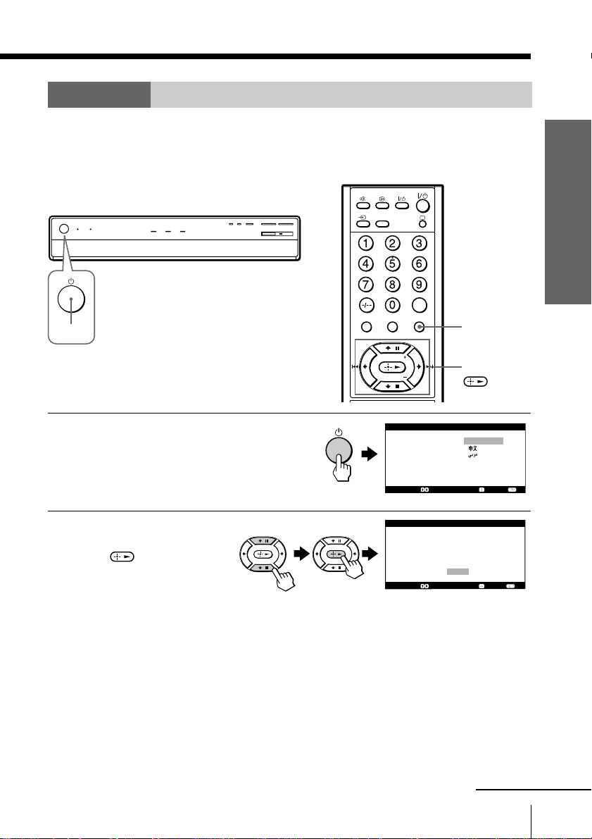
Step 4
Set up your TV automatically
When you first turned on the TV set, the “Initial Setup” menu will appear on the TV
screen. You can set the initial setting of “Language” and preset the channel
automatically.
Front of Media Receiver Unit
VIDEO
HD/DVD
Using Your New TV
1
Press 1 to turn on the
1
media receiver unit.
The “Initial Setup” menu
appears, and you can select
the on-screen language.
Press M/m to select the
2
desired language, then
press
.
“Start auto program now?”
appears.
OPTION MENU
JUMP
V CENTER
TWIN PROG
TWIN PROG
I n i t i a l S e t u p
L a n g u a g e :
S e l e c t :
I n i t i a l S e t u p
F i r s t p l e a s e
c a b l e / a n t e n n a
S t a r t a u t o
S e l e c t : C o n f i r m : E n d :
MENU
M/m/</,/
E n g l i s h
C o n f i r m : E n d :
c o n n e c t
p r o g r a m n o w ?
Yes
No
continued
Using Your New TV
17
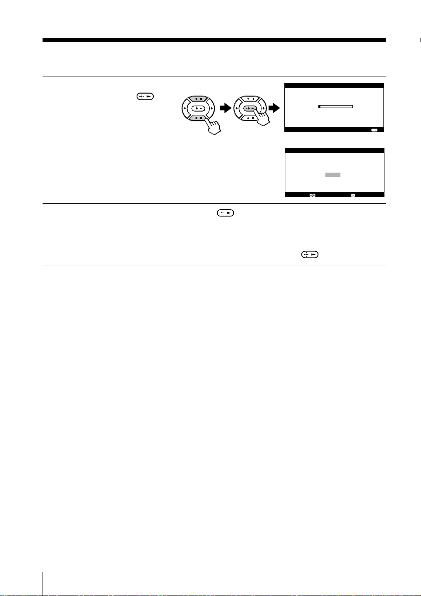
Getting Started (continued)
Press M/m to select
3
“Yes”, then press to
preset the channels
P r o g r a m :
T V S y s t e m :
V H F L o w :
automatically.
The screen will indicate
S e l e c t :
automatic presetting is in
progress. After channel
presetting is complete,
D i s p l a y t h i s m e n u n e x t t i m e ?
“Display this menu next
time?” appears.
Press M/m to select “No”, then press .
4
The “Initial Setup” menu will not appear again the next time you turn
on the media receiver unit by pressing 1.
To allow this menu to appear again, select “Yes”, then press
Tips
•You can immediately go to the end of the “Initial Setup” menu by pressing
MENU.
• If your TV has preset an unwanted channel or cannot preset a particular
channel, then preset your TV manually (see page 97).
A u t o P r o g r a m
0 9
A u t o
C o n f i r m :
I n i t i a l S e t u p
Y e s
N o
.
E n d :
E n d :S e l e c t : C o n f i r m :
18
Using Your New TV
Connecting optional components
You can connect optional audio/video components, such as a VCR,
a DTV (Digital Television) receiver, multi disc player, camcorder,
video game, or stereo system. To watch and operate the connected
equipment, see page 28.
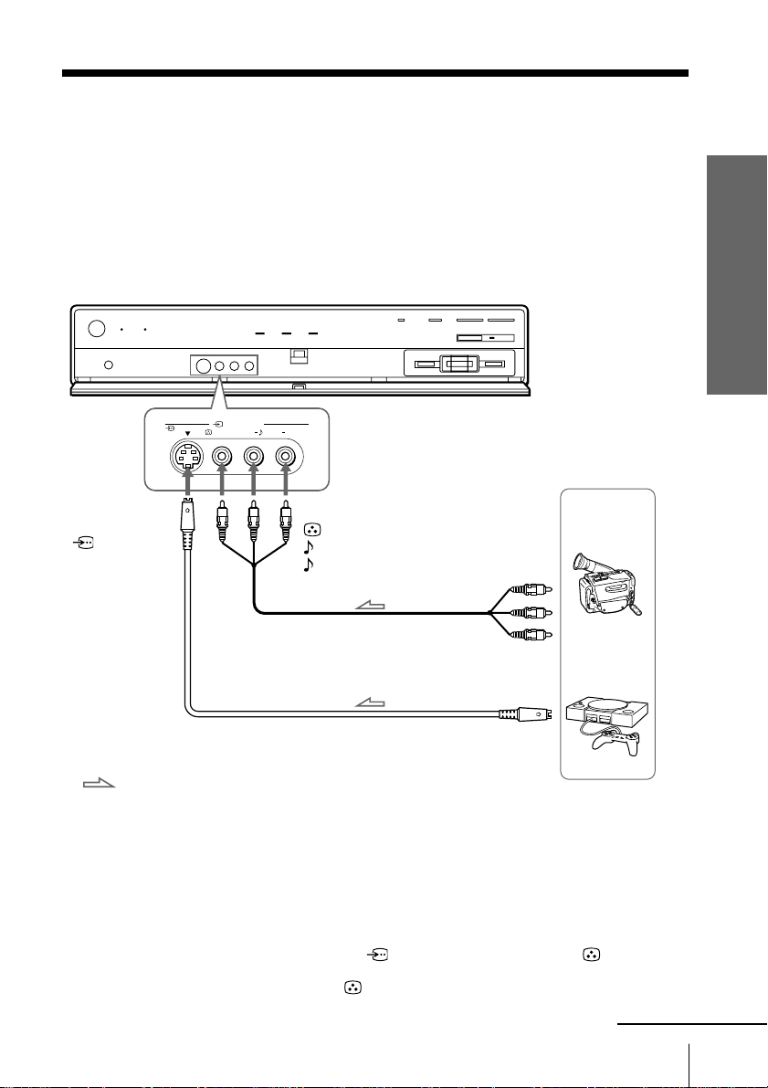
Connecting a camcorder/video game equipment
using t VIDEO IN (video input) 4 jacks
Front of Media Receiver Unit
VIDEO IN
VIDEO
(
MONO
4
)
AUDIO RL
S VIDEO
Using Your New TV
To t VIDEO IN
(video input) 4
S VIDEO
(S video input)
: Signal flow
To t VIDEO IN (video input) 4
VIDEO (yellow)
AUDIO-L (MONO) (white)
AUDIO-R (red)
Audio/Video cable
(not supplied)
or
S video cable (not supplied)
To video and
audio outputs
To S video
output
Camcorder
Video game
equipment
Notes
• When connecting video game equipment, display the “Features” menu
and select “On” for “Game Mode” to adjust the picture setting that is
suitable for video games (see page 93).
•You can also connect video equipment to the t VIDEO IN (video input)
1, 2, or 3 jacks at the rear of your media receiver unit.
• When you connect video equipment to the S video input, display the
“Setup” menu and select “Auto” for “S Input” (see page 106). If the
signals are input to both S VIDEO (S video input) and VIDEO
(video input), the S video signal is automatically selected. To view the
video signal input to VIDEO (video input), select “Off” for “S Input”.
continued
Using Your New TV
19
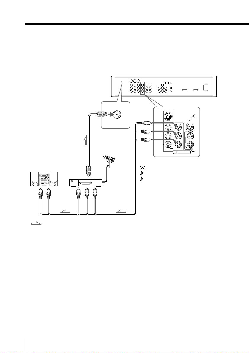
Connecting optional components (continued)
Connecting audio/video equipment using the T VIDEO OUT
(monitor output) jacks
Rear of Media Receiver Unit
8 VHF/UHF
To 8 VHF/UHF
Antenna
(antenna)
cable
(supplied)
Audio system
VCR
or
To audio
inputs
To video
and audio
inputs
Audio cable (not supplied) Audio/Video cable
: Signal flow
(not supplied)
Note
• If you select “HD/DVD 1” or “HD/DVD 2” on your TV screen (see page
28), sound will be heard but no picture will be output from T VIDEO
OUT (monitor output). This does not indicate a malfunction.
L
L
R
(
)
VAR/FIX
3
VIDEO OUT
To T VIDEO OUT (monitor output)
VIDEO (yellow)
AUDIO (VAR/FIX) -L (white)
AUDIO (VAR/FIX) -R (red)
20
Using Your New TV
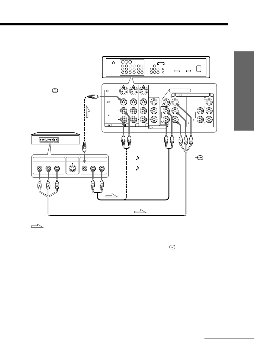
Connecting a DVD player
To t VIDEO IN
(video input) 1, 2 or 3
VIDEO (yellow)
Video cable
(not supplied)
DVD player
To video
output
COMPONENT VIDEO OUT
Y
CB CR
S VIDEO OUT
VIDEO
To audio
outputs
LINE OUT
R-AUDIO-L
Rear of Media Receiver Unit
S VIDEO
VIDEO
L
(
)
MONO
AUDIO
R
VIDEO IN
123
To AUDIO-L
(white)
AUDIO-R (red)
L
(
VAR/ FIX
VIDEO OUT
)
L
R
WOOFER OUT
1
Y
PB/C
PR/C
AUDIO
(
)
VAR
COMPONENT VIDEO IN
B
R
AUDIO
G
Y
PB/C
B
B
L
R
R
To
COMPONENT
VIDEO IN
(component
video input) 1
or 2
Using Your New TV
2
PR/C
R
To component
video output
Audio cable (not supplied)
Component video cable
: Signal flow
(not supplied)
• If the DVD player has the component video output jacks
Connect the component video cable and audio cable to the COMPONENT
VIDEO IN (component video input) 1 or 2 jacks.
You do not need to connect the video cable.
• If the DVD player does not have the component video output jacks
Connect the video cable and audio cable to the t VIDEO IN (video input) 1, 2 or 3
jacks.
Connect the audio cable to the corresponding video input.
continued
Using Your New TV
21
Connecting optional components (continued)
Notes
• Some DVD player terminals may be labeled differently:
Connect To (on the DVD player)
Y (green) Y
PB/CB (blue) Cb, B-Y or PB
PR/CR (red) Cr, R-Y or PR
• Connect nothing to the HD/VD jacks when connecting a DVD player to
COMPONENT VIDEO IN (component video input) 1 or 2 .
• If you select “HD/DVD 1” or “HD/DVD 2” on your TV screen (see page
28), sound will be heard but no picture will be output from T VIDEO
OUT (monitor output). This does not indicate a malfunction.
• When receiving a progressive signal through COMPONENT VIDEO
IN (component video input) 1 or 2, “DRC-MF”, “DRC Palette” and “Game
Mode” are not selectable.
• Since the high quality pictures on a DVD disc contain a lot of information,
picture noise may appear. In this case, display the “Picture” menu and
select “Personal” for “Picture Mode” (see page 82), then adjust the
sharpness (“Sharpness”) under “Picture Adjustment” (see page 83).
•You can also connect a DVD player to t VIDEO IN (video input) 1, 2 or 3
jacks on the media receiver unit.
22
Using Your New TV
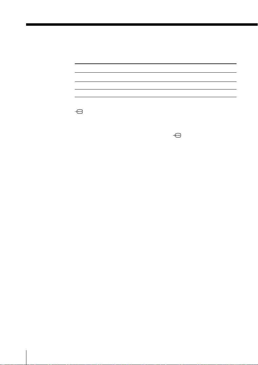
Connecting a DTV (digital television) receiver to
COMPONENT VIDEO IN (component video input) 2 jacks
Component video cable
(not supplied)
Digital TV receiver
To audio
outputs
Audio cable
(not supplied)
: Signal flow
Note
• The media receiver unit is equipped with the G/B/R/HD/VD inputs.
Rear of Media Receiver Unit
To
COMPONENT
VIDEO IN
(component
video input) 2
To component
video output
(
)
VAR
WOOFER OUT
COMPONENT VIDEO IN
1
Y
PB/C
AUDIO
B
AUDIO
PR/C
R
L
R
2
G
Y
PB/C
B
B
L
R
HD
VD
R
PR/C
R
VD
SYNC
To COMPONENT
VIDEO IN (component
video input) 2
AUDIO-L (white)
AUDIO-R (red)
If your DTV receiver is equipped with the Y/PB/PR output connectors,
connect it to the Y/PB/PR connectors of COMPONENT VIDEO IN
(component video input) 1 or 2. Connect nothing to the HD/VD
connectors of SYNC.
If your DTV receiver is not equipped with the Y/PB/PR output connectors,
connect it to the G/B/R/HD/VD connectors of COMPONENT
VIDEO IN (component video input) 2 and SYNC.
Using Your New TV
continued
Using Your New TV
23

Connecting optional components (continued)
Tip
• The TV accepts the following signal formats:
Total scanning line Effective scanning line fV (Hz)
1125i 1080i 50/60
750p 720p 50/60
625p 576p 50
625i 576i 50
525p 480p 60
525i 480i 60
24
Using Your New TV
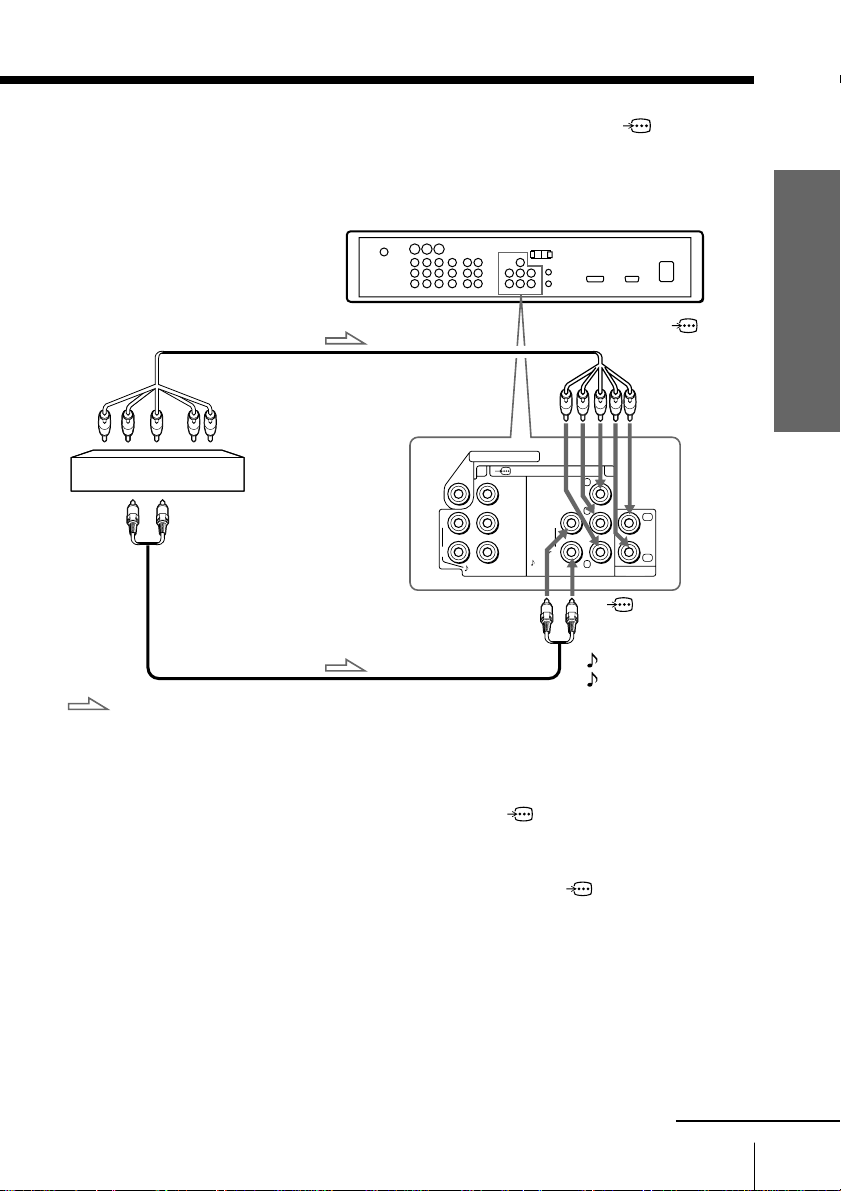
Connecting an amplifier
If you use an amplifier with a Dolby* surround decoder instead of
the TV’s audio system, you can use the TV’s speakers as the center
speaker for your audio system.
Using the speaker cords, connect the center speaker terminals of the
amplifier to the CENTER SP IN (center speaker input)
terminals on the media receiver unit.
Rear of Media Receiver Unit
To COMPONENT
VIDEO IN (component
video input) 1 or 2
Component
video cable
(not supplied)
To
COMPONENT
VIDEO IN
(component video
input) 1 or 2
AUDIO-L (white)
AUDIO-R (red)
To component
video output
L
R
Audio cable
(not supplied)
WOOFER OUT
1
Y
PB/C
PR/C
AUDIO
(
)
VAR
COMPONENT VIDEO IN
Y
PB/C
AUDIO
B
L
R
B
R
2
G
B
R
PR/C
R
C
HD
IN
OUT
VD
VD
SYNC CONTROL S
To digital
audio input
CENTER SP IN
120W MAX 8
Amplifier
Using Your New TV
To
CENTER SP IN
(center
speaker input)
DVD player
: Signal flow
To audio
outputs
To digital audio
output
Optical digital cable
(not supplied)
Front
speaker (L)
Rear
speaker (L)
Front
speaker (R)
Rear
speaker (R)
Woofer
Note
•To use the TV’s speakers as the center speaker, display the “Sound” menu
and select “On” for “Speaker Out” (see page 85) and press CENTER SP to
switch the center speaker mode to “CENTER IN Speaker” (see page 45).
* “Dolby” is a trademark of Dolby Laboratories.
continued
Using Your New TV
25
Connecting optional components (continued)
Connecting a sub woofer
Use a monaural audio cable to connect the media receiver unit’s WOOFER OUT jack
to the sub woofer’s input jack.
Rear of Media Receiver Unit
(
1
Y
PB/C
PR/C
)
VAR
COMPONENT VIDEO IN
B
R
AUDIO
G
Y
PB/C
B
B
L
R
R
PR/C
WOOFER OUT
L
R
AUDIO
2
R
Monaural audio cable
(not supplied)
To WOOFER OUT (VAR)
: Signal flow
Using the CONTROL S Feature
CONTROL S allows you to control your system and other Sony equipment with one
remote control. In addition to allowing you to control multiple devices with one
remote control, the CONTROL S feature allows you to always point your remote
control at your TV, instead of having to point it at the other equipment, which might
be hidden or out of direct line of sight.
Use CONTROL S IN to send
signals to the TV.
Use CONTROL S OUT to send
signals to connected equipment.
IN
OUT
CONTROL S
L
R
WOOFER OUT
1
AUDIO
Rear of Media Receiver Unit
(
)
VAR
COMPONENT VIDEO IN
Y
PB/C
B
AUDIO
PR/C
R
2
G
Y
PB/C
B
B
L
R
R
PR/C
R
C
HD
IN
OUT
VD
VD
SYNC CONTROL S
CENTER SP IN
120W MAX 8
26
Using Your New TV
Watching the TV
This section explains various functions
and operations used while watching the
TV. Most operations can be done using
the remote.
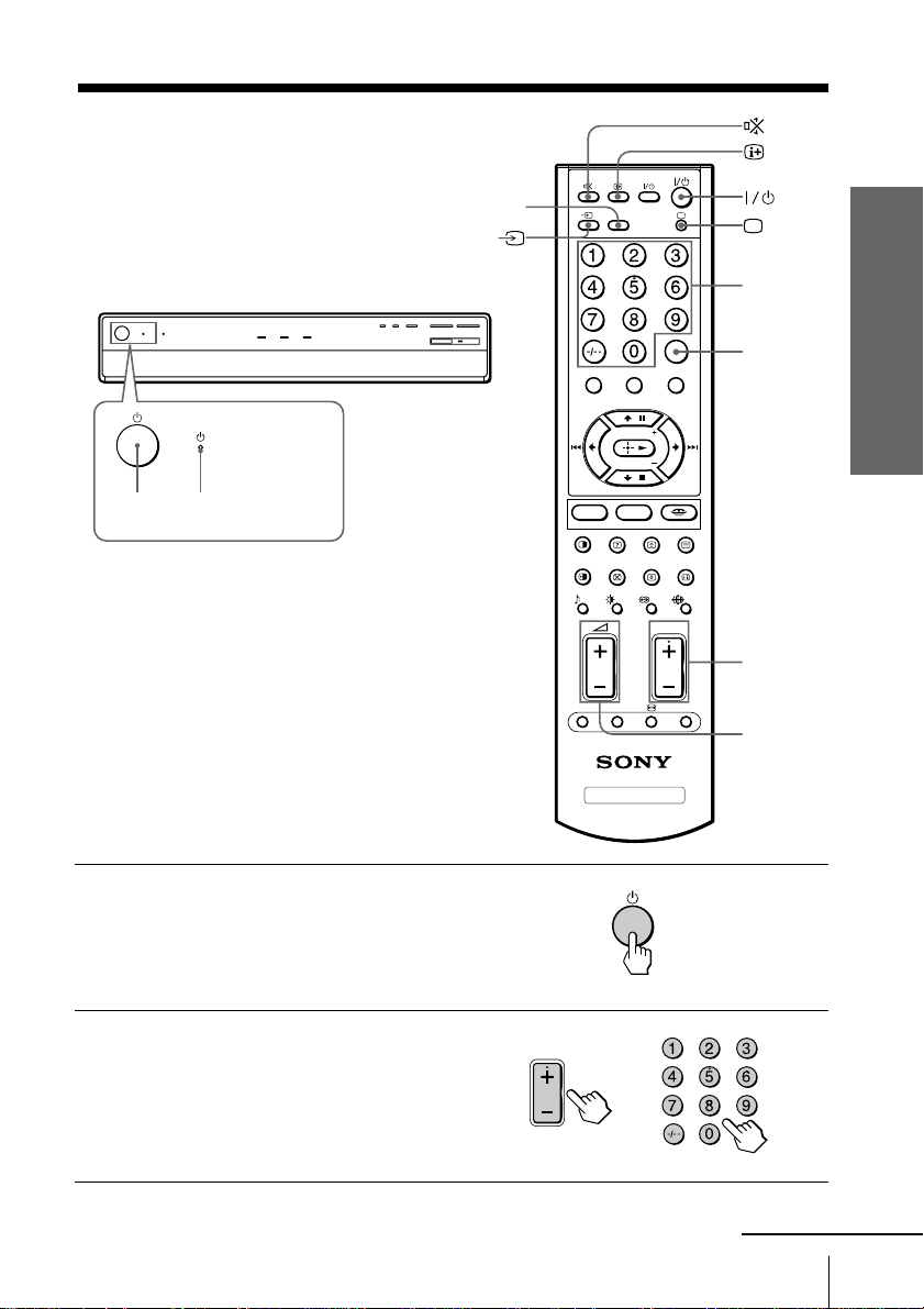
1
1 STANDBY
indicator
HD/DVD
VIDEO
HD/DVD
V CENTER
TWIN PROG
TWIN PROG
PALETTE
TV
JUMP
MENU
MEMORY STICK
PROG
OPTION
MODE
DRC-MF
CENTER SP RESET A/B
Using Your New TV
Number
buttons
JUMP
PROG
+/–
2 +/–
Press 1 to turn on the media
1
receiver unit.
When the TV is in standby mode (the 1
STANDBY indicator on the media receiver
unit is lit red), press !/1 on the remote.
Press PROG +/– or the number
2
buttons to select the TV
channel.
For double digit numbers, press
-, then the number (e.g., for 25,
press -, then 2 and 5).
PROG
or
Using Your New TV
continued
27
Watching the TV (continued)
Note
• When you turn on the TV, either the program number or video mode is
displayed for approximately 20 seconds. The Eco Mode ( ) icon will
also appear if “Eco Mode” in the “Features” menu is set to “On” (see page
92).
To select a TV program quickly
1Press and hold PROG +/–.
2 Release PROG +/– when the desired program number appears.
Note
• When you select a TV program quickly, the picture may be disrupted.
This does not indicate a malfunction.
Additional tasks
To Press
Turn off temporarily
Turn off completely
Adjust the volume
Mute the sound
Watch the video input
(VCR, camcorder, etc.)
Watch the component
input
(DVD, DTV receiver)
Jump back to the
previous channel
Display the on-screen
information*
@/1.
The 1 STANDBY indicator on the media
receiver unit lights up red.
1 on the media receiver unit.
2 +/–.
%.
t (or t INPUT on the media receiver unit)
several times to select “VIDEO 1”, “VIDEO 2”,
“VIDEO 3”, “VIDEO 4”, “HD/DVD 1”, “HD/
DVD 2” or TV screen.
To return to the TV screen, press a (or t
INPUT on the media receiver unit) several
times.
HD/DVD to select “HD/DVD 1” or “HD/DVD
2”.
To return to the TV screen, press a (or t
INPUT on the media receiver unit) several
times.
JUMP.
.
28
Using Your New TV
* Some picture/sound settings, and either the program number or video
mode are displayed. The on-screen display for the picture/sound settings
disappears after about 5 seconds.
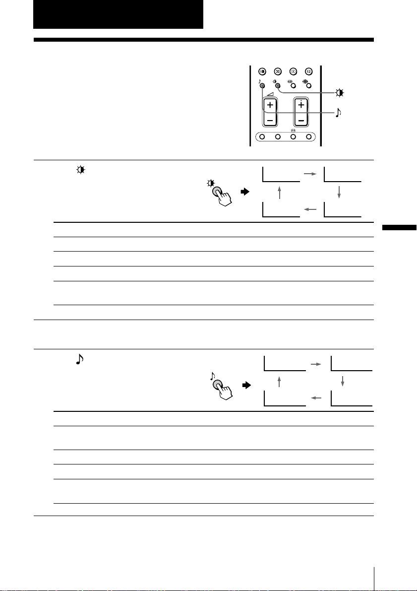
Advanced Operations
Selecting the picture and sound modes
You can select picture and sound modes
and adjust the setting to your preference
in the “Personal” option.
Selecting the picture mode
PROG
CENTER SP RESET A/B
Press repeatedly until
the desired picture mode
Dynamic
is selected.
Personal
Select To
“Dynamic” receive high contrast pictures.
“Standard” receive normal pictures.
“Hi-Fine” receive higher resolution pictures with mild contrast.
“Personal” receive the last adjusted picture setting from the “Picture
Adjustment” menu under the “Picture” menu (see page 83).
Selecting the sound mode
Press repeatedly until
the desired sound mode is
selected.
Select To
“Dynamic” listen to dynamic and clear sound that emphasizes both the low
and high tones.
“Drama” listen to sound that emphasizes voice and high tones.
“Soft” receive soft sound.
“Personal” receive the last adjusted sound setting from the “Sound
Adjustment” menu under the “Sound” menu (see page 84).
9
Dynamic
9
Personal
Standard
Hi-Fine
9
Drama
9
Soft
Advanced Operations
Tip
•You can also set the picture and sound modes using the menu (see
“Changing the “Picture” setting” on page 81 and “Changing the “Sound”
setting” on page 84).
Advanced Operations
29
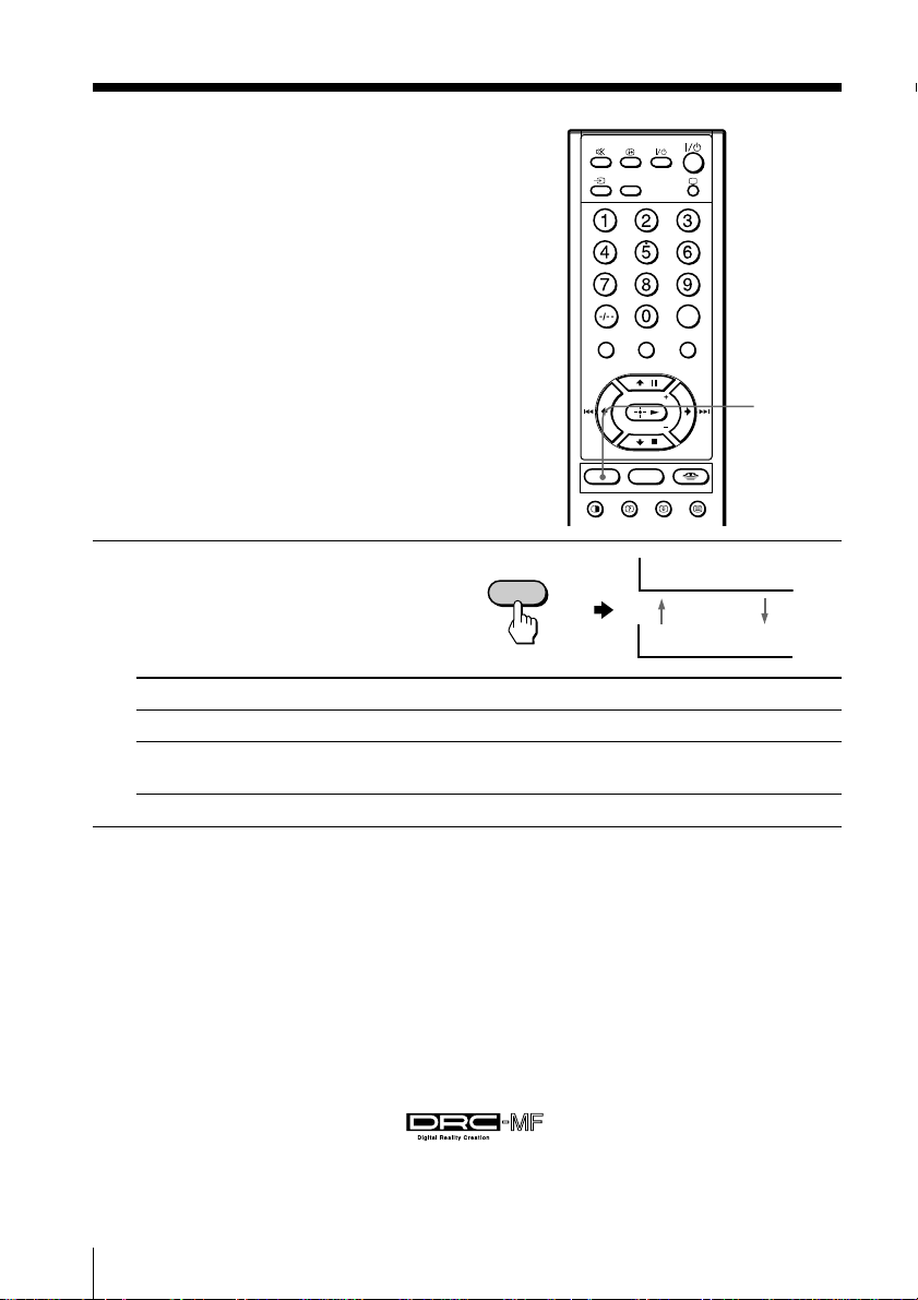
Viewing higher
OPTION
DRC-MF
MEMORY STICK
MENU
JUMP
HD/DVD
V CENTER
MODE PALETTE
VIDEO
TWIN PROG
TWIN PROG
quality pictures
— “DRC-MF MODE”
The Digital Reality Creation-Multi
Function (DRC-MF) feature allows you to
enjoy higher quality pictures on your TV.
You can select from among two DRC-MF
modes: “DRC1250” to watch super real
(higher resolution) pictures, or
“Progressive” for still pictures.
DRC-MF
MODE
Press DRC-MF MODE
repeatedly until you receive
the desired picture quality.
MODE
DRC-MF
DRC-MF: DRC1250
DRC-MF: Progressive
Select To
“DRC1250” select higher resolution pictures.
“Progressive” reduce jitter of any small areas or scanning lines (e.g., letters or the
edge of objects) on the screen.
Tip
• When the broadcast signal is weak, you may see some dots or noise on the
TV screen. To reduce this interference, display the “Picture” menu and
select “Personal” for “Picture Mode” (see page 82), then adjust
“Sharpness” under “Picture Adjustment” to reduce the sharpness (see
page 83).
Note
• The DRC-MF mode is not selectable when the “Game Mode” is turned
“On”. The mode is not available for HD (high-definition) or progressive
input signal, or the picture recorded on a “Memory Stick”.
The DRC-MF logo ( ) and “DRC-MF” are trademarks of
Sony Corporation.
30
Advanced Operations
 Loading...