

Sony WALKMAN WM-SR10 Service Manual
WM-SR10
E Model
SERVICE MANUAL
RADIO CASSETTE-CORDER
Sony Corporation
Personal Audio Company
Published by Sony Engineering Corporation
9-874-215-02
2003E16-1
© 2003.05
SPECIFICATIONS
Ver 1.1 2003. 05
Model Name Using Similar Mechanism WM-GX221
Tape Transport Mechanism Type MT-WMGX221-175
Frequency range
FM: 87.5 - 108 MHz (Saudi Arabia)
87.6 - 107.9 MHz (Other countries)
AM: 526.5 - 1 606.5 kHz (Saudi Arabia)
531 - 1 602 kHz (Other countries)
Frequency response Playback: 40 - 15 000 Hz
Recording: 100 - 8 000 Hz
Input Microphone (MIC) jack
Output Headphones (i) jack, Load impedance 8 - 300 Ω
Speaker
Approx. 5 cm (2 in.) dia.
Power requirement 3V DC
Batteries R6 (AA) x 2
External DC 3 V power sources
Dimensions
Approx. 112.0 × 82.5 × 37.5 mm (4
1
⁄2 × 3 1⁄4 × 1 1⁄2 inches)
(w/h/d), excl. projecting parts and controls
Mass Approx. 187 g (6.6 oz) (main unit only)
Supplied accessory
Stereo headphones or Stereo earphones (1)
Design and specifications are subject to change without
notice.
Battery life* (approximate hours)
Sony alkaline LR6(SG)**Sony R6P(SR)
(using headphones/earphones)
Tape playback 24 7
Radio reception 48 15
Mic recording 20 4.5
Radio recording 12 3
(using the speaker)
Tape playback 15 4.5
Radio reception 26 6
Radio recording 11.5 3
* Measured value by the standard of JEITA (Japan Electronics and
Information Technology Industries Association).
(Using a Sony HF series cassette tape)
** When using LR6 (SG) Sony “STAMINA” alkaline dry batteries
(produced in Japan).
Note
The battery life may be shorter depending on the operating
condition, the surrounding temperature and battery type.

2
TABLE OF CONTENTS
WM-SR10
Notes on chip component replacement
•Never reuse a disconnected chip component.
• Notice that the minus side of a tantalum capacitor may be
damaged by heat.
Flexible Circuit Board Repairing
•Keep the temperature of soldering iron around 270˚C
during repairing.
• Do not touch the soldering iron on the same conductor of the
circuit board (within 3 times).
• Be careful not to apply force on the conductor when soldering
or unsoldering.
Unleaded solder
Boards requiring use of unleaded solder are printed with the leadfree mark (LF) indicating the solder contains no lead.
(Caution: Some printed circuit boards may not come printed with
the lead free mark due to their particular size.)
: LEAD FREE MARK
Unleaded solder has the following characteristics.
• Unleaded solder melts at a temperature about 40°C higher than
ordinary solder.
Ordinary soldering irons can be used but the iron tip has to be
applied to the solder joint for a slightly longer time.
Soldering irons using a temperature regulator should be set to
about 350°C.
Caution: The printed pattern (copper foil) may peel away if the
heated tip is applied for too long, so be careful!
• Strong viscosity
Unleaded solder is more viscous (sticky, less prone to flow) than
ordinary solder so use caution not to let solder bridges occur such
as on IC pins, etc.
• Usable with ordinary solder
It is best to use only unleaded solder but unleaded solder may
also be added to ordinary solder.
1. SERVICE NOTE ............................................................... 3
2. GENERAL .......................................................................... 4
3. DISASSEMBLY
3-1. Front Cabinet Assy.......................................................... 5
3-2. MAIN Board ................................................................... 6
3-3. Mechanism Deck (MT-WMGX221-175) ....................... 6
3-4. Belt (CAP), M601, HRP901, HE901 .............................. 7
3-5. Cassette Holder Sub Assy ...............................................7
4. MECHANICAL ADJUSTMENT .................................. 8
5. ELECTRICAL ADJUSTMENT .................................... 8
6. DIAGRAMS ...................................................................... 10
6-1. Block Diagram – Tuner Section –................................. 11
6-2. Block Diagram – Main Section – ................................. 12
6-3. Printed Wiring Boards .................................................. 13
6-4. Schematic Diagram – MAIN Board (1/2) –.................. 14
6-5. Schematic Diagram – MAIN Board (2/2) –.................. 15
6-6. IC Block Diagrams ....................................................... 16
7. EXPLODED VIEWS
7-1. Overall Section ............................................................. 17
7-2. Cabinet (Front) Section ................................................. 18
7-3. Mechanism Deck Section-1 (MT-WMGX221-175) ..... 19
7-4. Mechanism Deck Section-2 (MT-WMGX221-175) ..... 20
8. ELECTRICAL PARTS LIST .......................................21

3
WM-SR10
SECTION 1
SERVICE NOTE
In this set, record/play mode is detected using the switch S704 (TAPE POWER).
S704 is mounted on the MAIN board. If MAIN board is removed, it becomes impossible to detect
record/play mode.
Where MAIN board is removed, when you measure operation and voltage of each part of the mechanism
deck, please turn on S704.
– MAIN Board (SIDE A) —
S704
4
WM-SR10
SECTION 2
GENERAL
This section is extracted
from instruction manual.
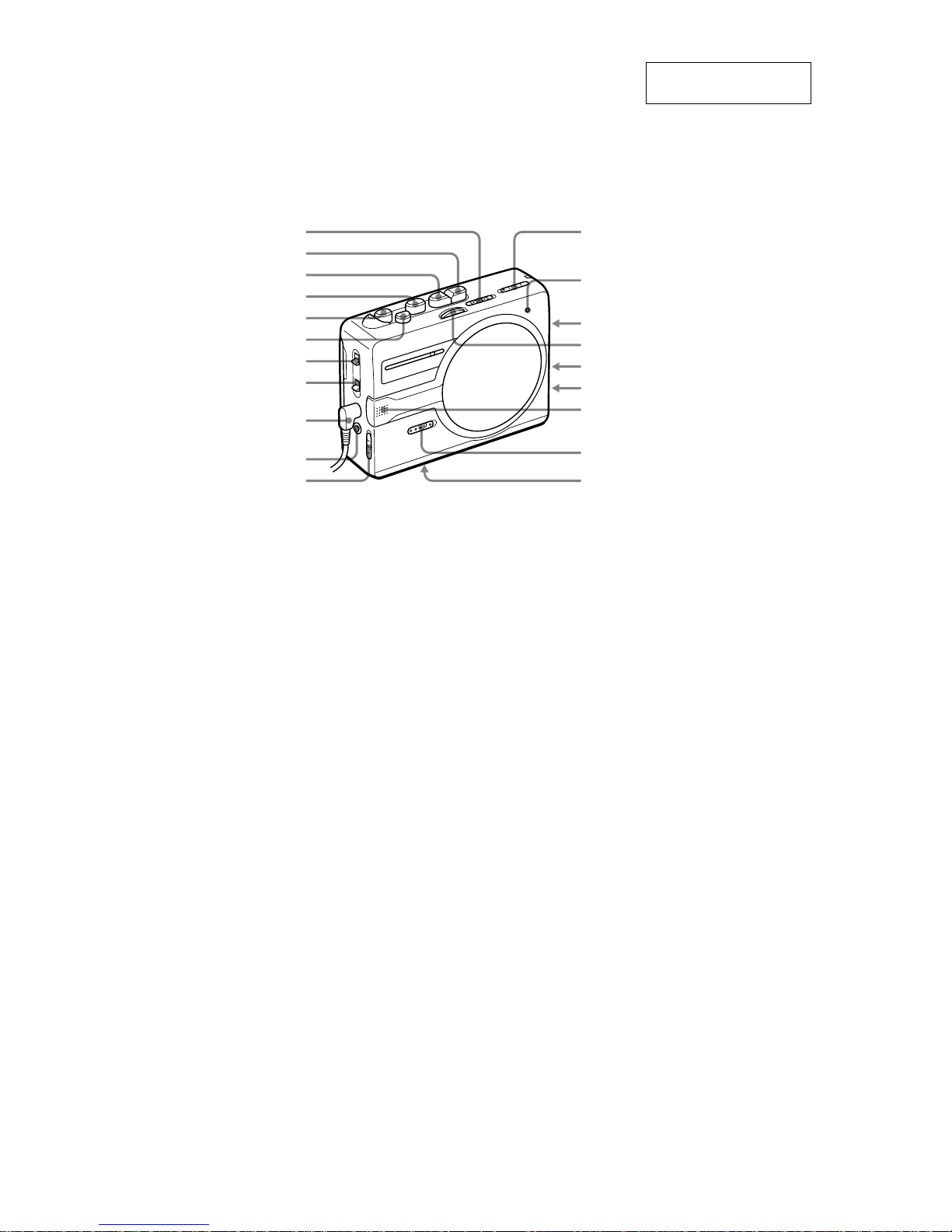
* There is a tactile dot beside VOL on the main unit to show the direction to turn up the volume.
** The button/jack has a tactile dot.
NPLAY**
MFF/CUE
DC IN 3 V
mREW/REVIEW
xSTOP
SPEAKER/ i
VOL*
TUNING
i
zREC
(RADIO OFF) TAPE/
AM/FM
AVLS
BATT indicator
PAUSE
MIC (PLUG IN POWER)**
SOUND BOOST
ISS
Built-in microphone
Battery compartment
FM ST/MONO
• LOCATION OF CONTROLS
5
WM-SR10
SECTION 3
DISASSEMBLY
Note : Disassemble the unit in the order as shown below.
Note : Follow the disassembly procedure in the numerical order given.
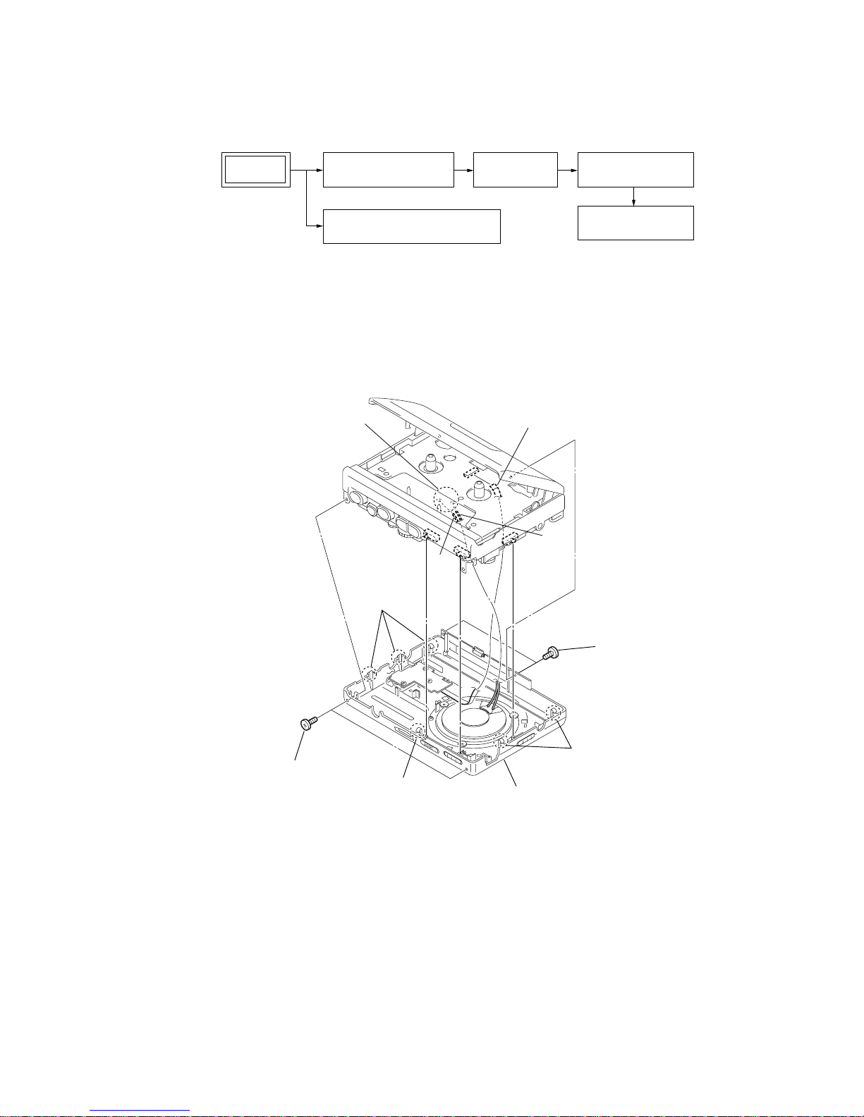
3-1. Front Cabinet Assy
SET
CASSETTE HOLDER SUB ASSY
FRONT CABINET ASSY MAIN BOARD
MECHANISM DECK
(MT-WMGX221-175)
BELT (CAP), M601,
HRP901, HE901
3
three claws
5
two claws
4
claw
6
flexible flat cable
(CN701)
8
front cabinet assy
1
two screws
(TP 1.7
×
3.7)
2
two screws
(M1.4) (EG)
7
Remove soldering
from the two points.
RED
WHT
6
WM-SR10
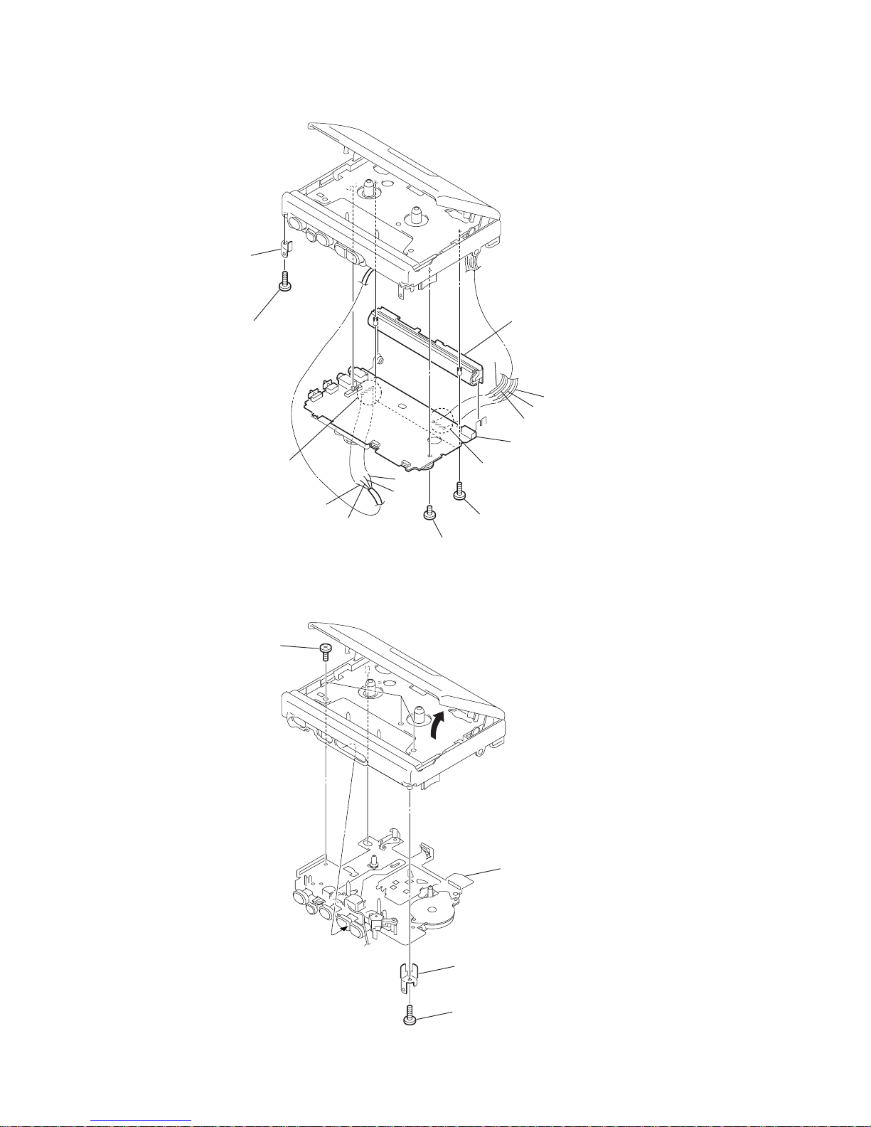
3-2. MAIN Board
3-3. Mechanism Deck (MT-WMGX221-175)
4
plate connector (R)
1
3
screw
(TP B1.7 × 4)
2
three screws
(IB LOCK)
5
mechanism deck
(MT-WMGX221-175)
1
screw
(TP B1.7
×
4)
5
screw
(M1.4
×
3)
2
plate connector (L)
4
Remove soldering
from the four points.
3
Remove soldering
from the four points.
RED
RED
BLU
GND
WHT
WHT
BLK
ORG
6
two screws
(TP B1.7
×
4)
7
MAIN board
8
joint cover
7
WM-SR10
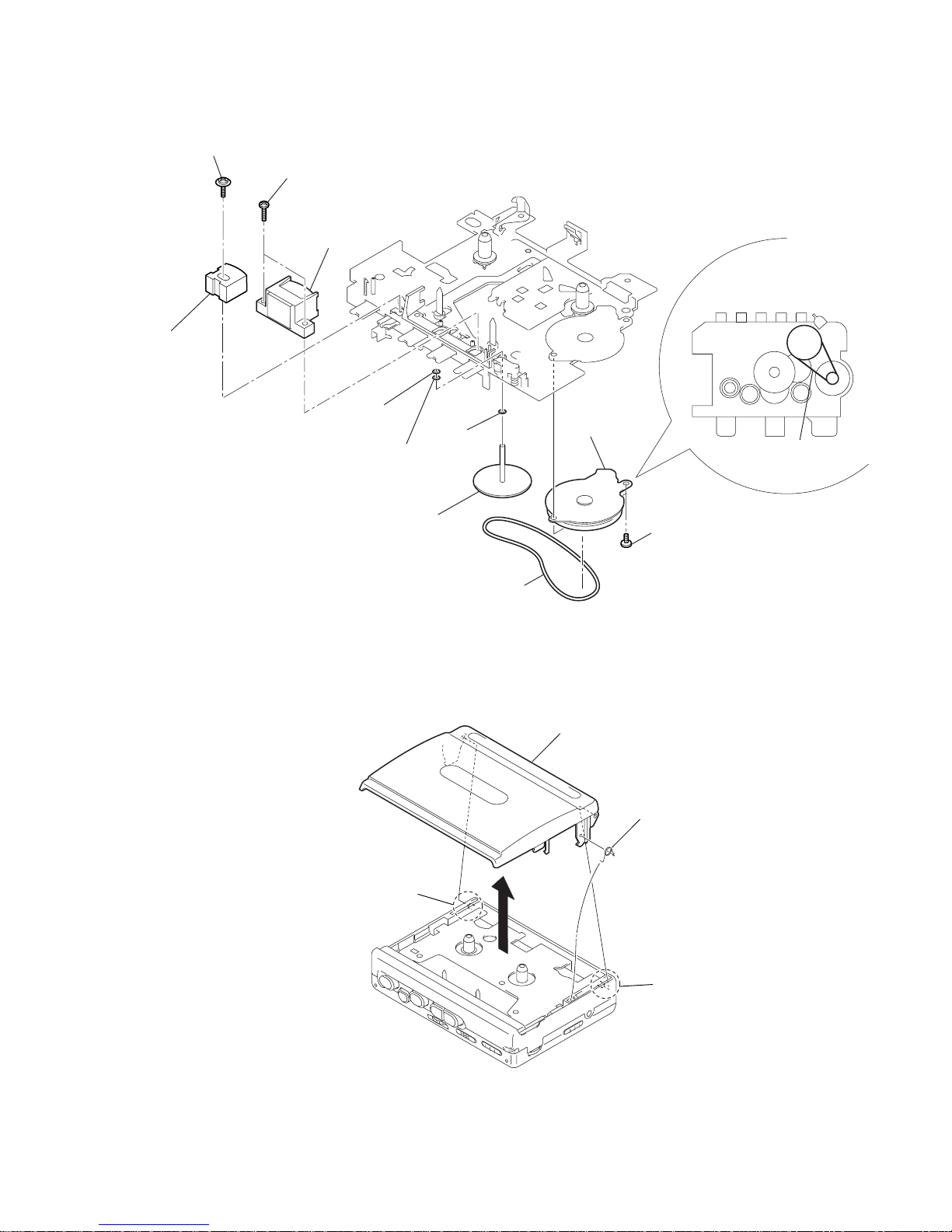
3-4. Belt (CAP), M601, HRP901, HE901
two screws (M1.4)
2
M601
(capstan/reel
motor)
3
1
7
6
capstan fly assy (AR)
washer
5
washer
4
9
qa
8
washer
(stopper N)
two screws
HE901
(erase head)
0
screw
HRP901
(REC/PB head)
Attaching belt (CAP).
belt (CAP)
belt (CAP)
z
3-5. Cassette Holder Sub Assy
4
spring (torsion
)
2
boss
5
cassette holder sub assy
3
1
boss
8
WM-SR10
SECTION 4
MECHANICAL ADJUSTMENT
SECTION 5
ELECTRICAL ADJUSTMENT
PRECAUTION
1. Specified voltage: 2.5 V (DC)
2. Switch and control position
VOL : MAX
SPEAKER : OFF
AVLS : NORM
SOUND BOOST : OFF
PAUSE : OFF
ISS : 1
FM MODE : FM ST
TAPE SECTION
Tape Speed Adjustment
Procedure:
1. Enter the FWD playback mode.
2. Adjust RV601 so that the value of the frequency counter reading
becomes 3,000 Hz.
Specification value:
Frequency counter
2,985 Hz – 3,015 Hz
3. Check that the frequency deviation at the beginning and ending
of a tape is within 1.5 % (45 Hz).
Adjustment Location : MAIN Board (see page 9)
PRECAUTION
1. Clean the following parts with a denatured-alcohol-moistened
swab:
record/playback/erase head pinch roller
rubber belts capstan
2. Demagnetize the record/playback head with a head demagnetizer. (Do not bring a head demagnetizer close to the erase
head.)
3. Do not use a magnetized screwdriver for the adjustments.
4. The adjustments should be performed with the rated power
supply voltage unless otherwise noted.
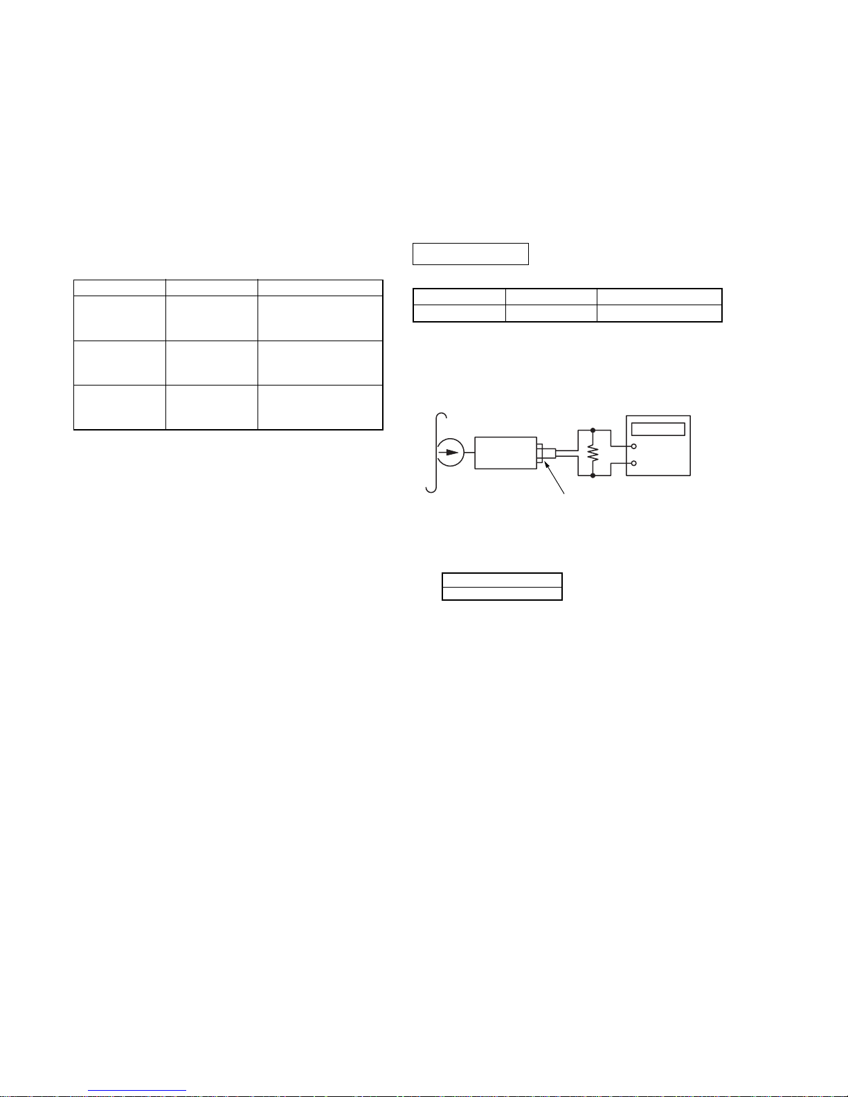
• Torque Measurement
Signal
3 kHz, 0 dB
Used for
Ta pe Speed Adjustment
Tape
WS-48A
Mode
FWD
FWD
Back Tension
FF, REW
Tor que Meter
CQ-102D
CQ-102D
CQ-201B
Meter Reading
19.6 to 39.2 mN•m
(20 to 40 g•cm)
(0.28 to 0.56 oz•inch)
0.49 to 4.9 mN•m
(0.5 to 5.0g•cm)
(0.0069 to 0.069 oz•inch)
More than 49 mN•m
(More than 50 g•cm)
(More than 0.69 oz•inch)
Test tape
WS-48A
(3kHz, 0dB)
Set
2
jack (J301)
16
Ω
Frequency counte
r
+
–
 Loading...