

Sony Walkman WM-FX571 Service Manual
– 1 –
Model Name Using Similar Mechanism WM-FX551/FX553
Tape Transport Mechanism Type MF-WMFX551-125
SERVICE MANUAL
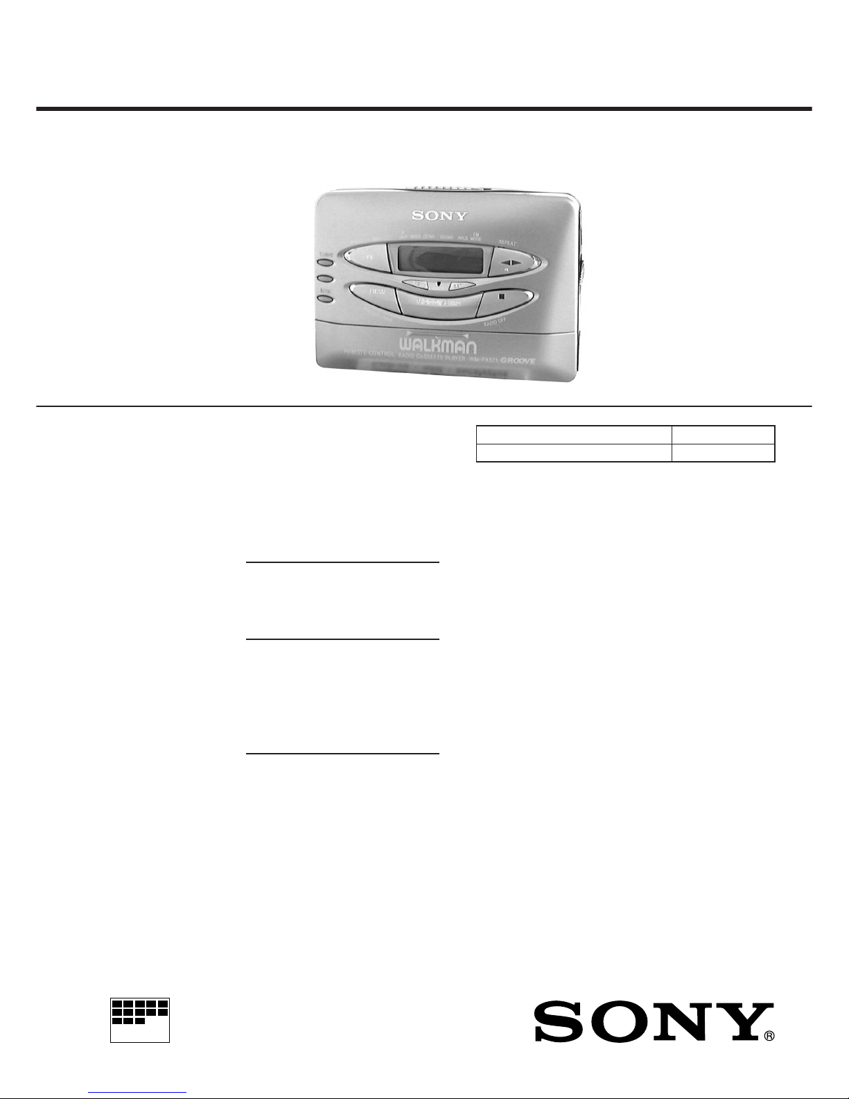
Tourist Model
WM-FX571
RADIO CASSETTE PLAYER
Ver 1.0 1999. 03
SPECIFICATIONS
Radio section
Frequency range
FM : 87.5 – 108 MHz
AM: 531 – 1,602 kHz
Tape section
Frequency response
(Dolby NR off)
Playback : 20 – 18,000 Hz
Output
Headphones (2 REMOTE jack)
Load impedance 8 – 300 Ω
General
Power requirements
1.5 V
One R6 (size AA) battery
Rechargeable battery
Dimensions (w/h/d)
Approx. 109 × 79.2 × 29.4 mm
(4 3/8 × 3 1/8 × 1 3/16 inches) incl.
projecting parts and controls
Mass
Approx. 150 g (5.3 oz)
Approx. 210 g (7.5 oz) incl.
a battery and a cassette
Supplied accessories
Stereo earphones with remote
control MDR-WMF653 (1)
Battery charger BC-820T (1)
AC plug adaptor (1)
Rechargeable battery (NC-AA) (1)
Battery R6P (SR) (1)
Carrying pouch (1)
Design and specifications are subject to
charge without notice.
Manufactured under license from Dolby Laboratories
Licensing Corporation.
“DOLBY” and the double-D symbol a are trademarks
of Dolby Laboratories Licensing Corporation.
MICROFILM

– 2 –
TABLE OF CONTENTS
1. GENERAL ....................................................................3
2. SERVICE NOTE.......................................................... 3
3. DISASSEMBLY
3-1. Case Assy ............................................................................ 4
3-2. Tuner Board ........................................................................ 4
3-3. Audio Board ........................................................................ 5
3-4. Cassette Lid Assy................................................................ 5
3-5. Tape Mechanism Deck ........................................................ 6
4. MECHANICAL ADJUSTMENTS..............................7
5. ELECTRICAL ADJUSTMENTS
Tape Section ............................................................................ 7
Tuner Section........................................................................... 8
6. DIAGRAMS
6-1. Block Diagram .................................................................... 9
6-2. IC Pin Description............................................................. 11
6-3. Printed Wiring Boards –Tuner Section– ........................... 13
6-4. Schematic Diagram –Tuner Section–................................ 17
6-5. Schematic Diagram –Audio Section– ............................... 20
6-6. Printed Wiring Board –Audio Section– ............................ 23
7. EXPLODED VIEWS
7-1. Cabinet Section ................................................................. 29
7-2. Audio and Tuner Board Section........................................ 30
7-3. Tape Mechanism Section .................................................. 31
8. ELECTRICAL PARTS LIST .................................... 32
Flexible Circuit Board Repairing
• Keep the temperature of the soldering iron around 270˚C during
repairing.
• Do not touch the soldering iron on the same conductor of the
circuit board (within 3 times).
• Be careful not to apply force on the conductor when soldering
or unsoldering.
Notes on Chip Component Replacement
• Never reuse a disconnected chip component.
• Notice that the minus side of a tantalum capacitor may be dam-
aged by heat.
– 3 –
screw
(M1.4 × 5.0)
screw (M1.4
×
5.0)
TUNER board
screw (M1.7
×
4.0
)
screw
(M1.4 × 5.0)
JIG
AUDIO board
0
!¡
!™
!£
!¢
!∞
!§
!¶
9
8
7
6
5
4
3
2
1
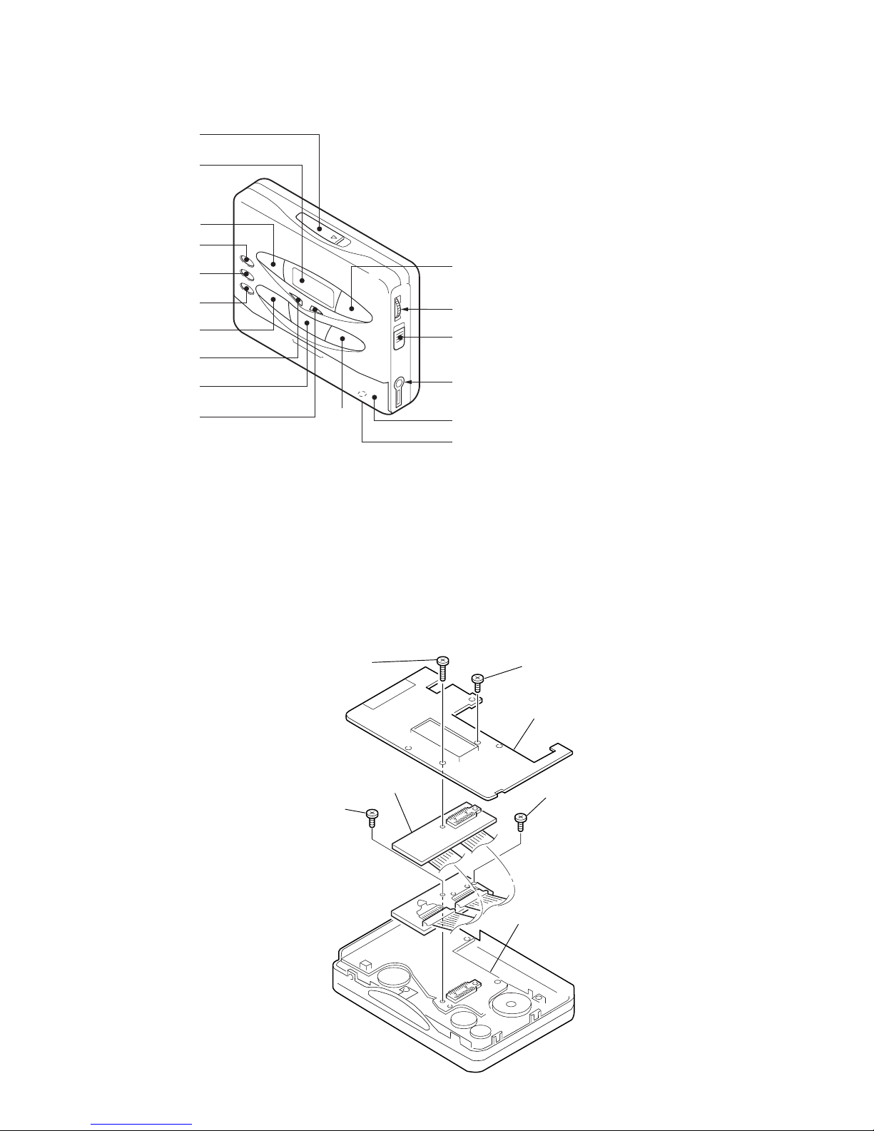
SECTION 1
GENERAL
• LOCATION OF CONTROLS
SECTION 2
SERVICE NOTE
• Regarding the method of adjustment and voltage check, perform sections 3-1 and 3-2 of the DISASSEMBLY, and attach the JIG (ext ension
cable) to the AUDIO board as shown below.
JIG Part No.: J-2503-005-A
1 OPEN knob
2 Display window
3 PRESET + /AMS FF (Fast Forward) button
4 TUNING + button
5 TUNING – button
6 ENTER button
7 PRESET – /AMS REW (Rewind) button
8 MENU button
9 RADIO ON/BAND button
!º SET button
!¡ p /RADIO OFF button
!™ “” /REPEAT button
!£ VOLUME control
!¢ C HOLD knob
!∞ 2 REMOTE jack
!§ Battery case
!¶ DC IN 1.5V jack
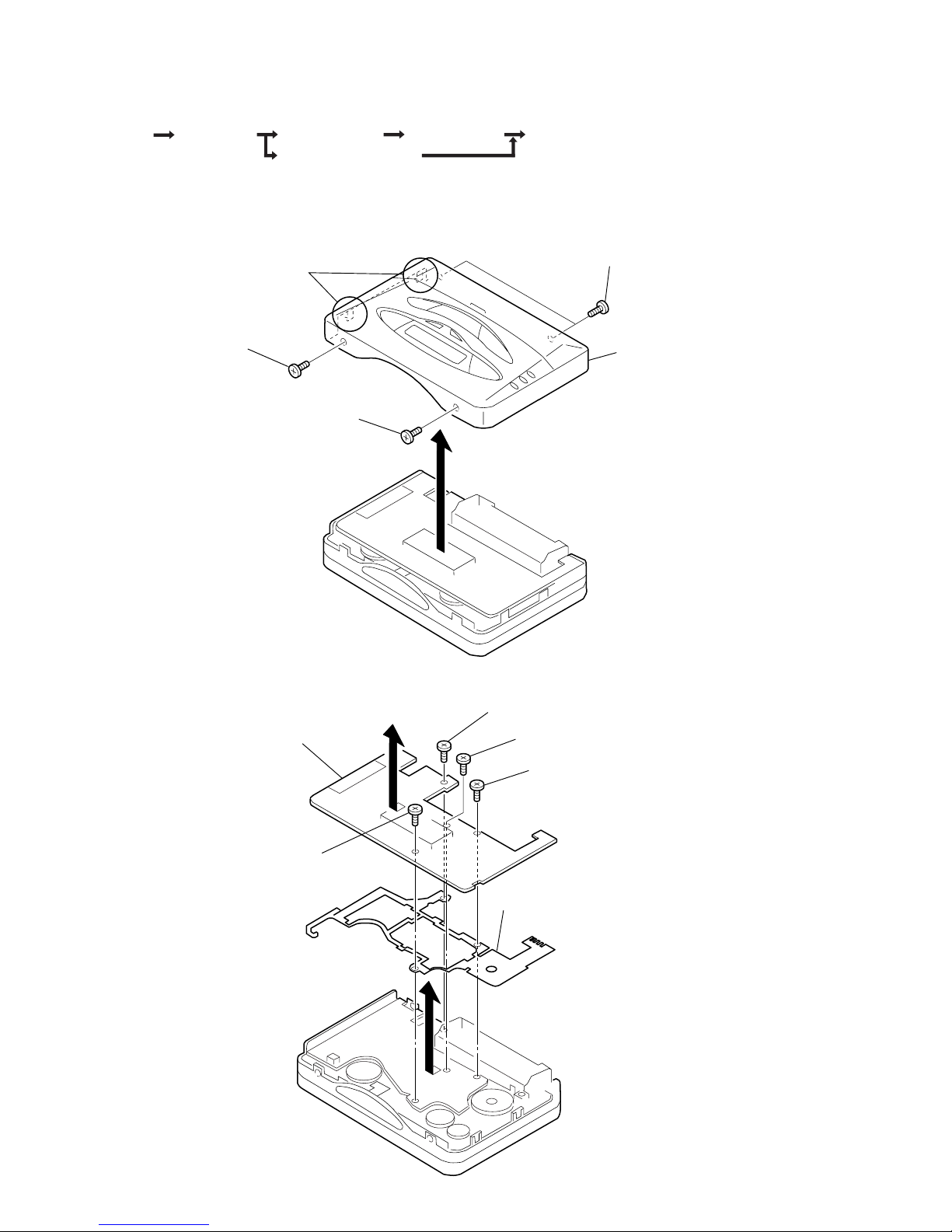
– 4 –
1
screw (M1.7 × 6)
5
TUNER board
4
3
screw
(M1.4
×
4.5)
7
guide (TU)
6
2
screw (M1.7 × 3)
1
screw (M1.7 × 6
)
6
case assy
4
claws
3
screws
(M1.4
×
2.2)
1
screw
(M1.4
×
2.2)
2
screw
(M1.4
×
3.0)
5
CASE ASSY
TUNER BOARD
AUDIO BOARD
CASSETTE LID ASSY
TAPE MECHANISM DECK
SET
SECTION 3
DISASSEMBLY
Note : Follow the disassembly procedure in the numerical order given.
3-1. CASE ASSY
3-2. TUNER BOARD
Note : Disassemble the unit in the order as shown below.
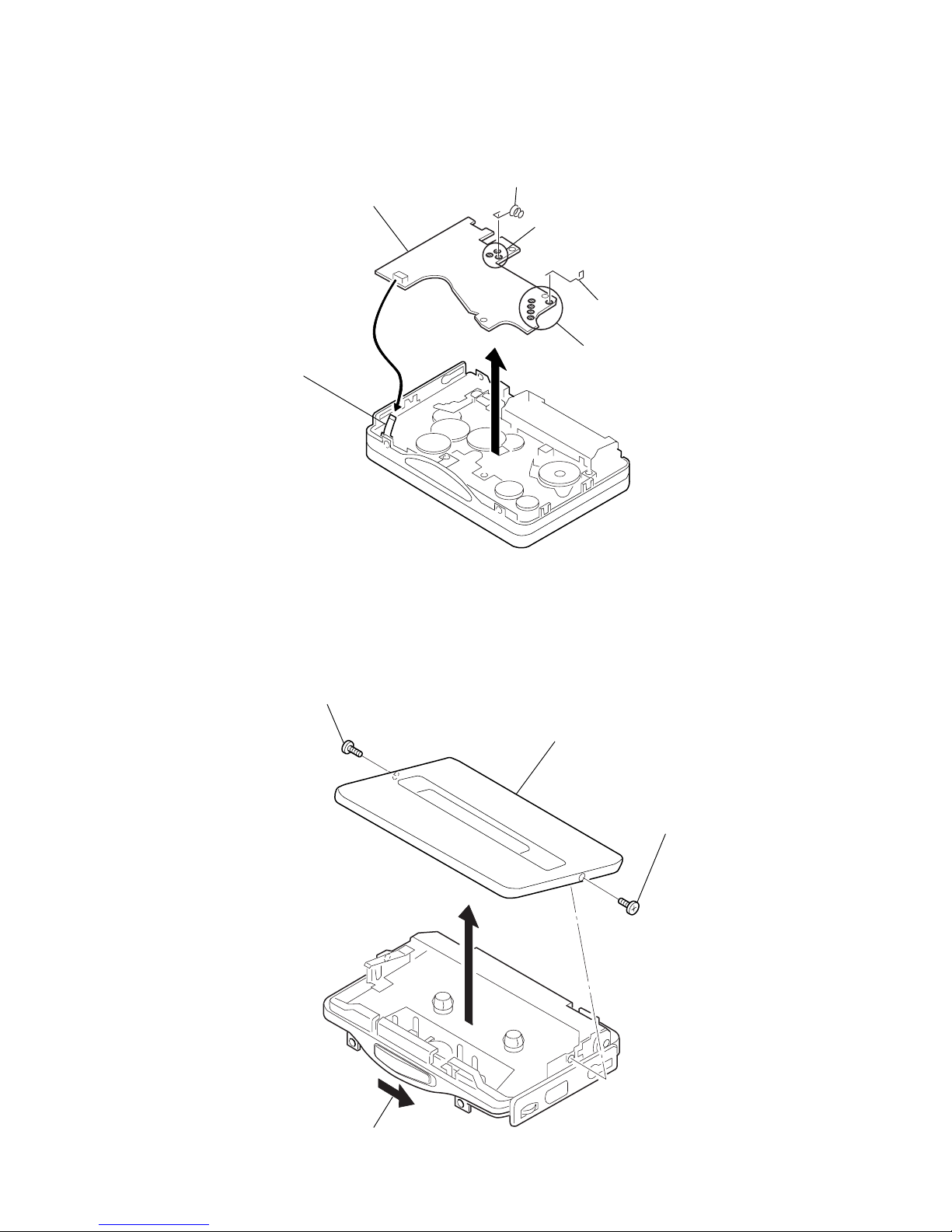
– 5 –
2
screw (M1.4 × 2)
5
cassette lid assy
3
screw (M1.4 × 1.6
)
1
OPEN button
4
7
AUDIO board
1
Unsolder the 3 places.
2
battery terminal (–)
4
battery terminal (+)
3
Unsolder the 5 places.
5
Flexible board
6
3-3. AUDIO BOARD
3-4. CASSETTE LID ASSY
– 6 –
2
1
3
4
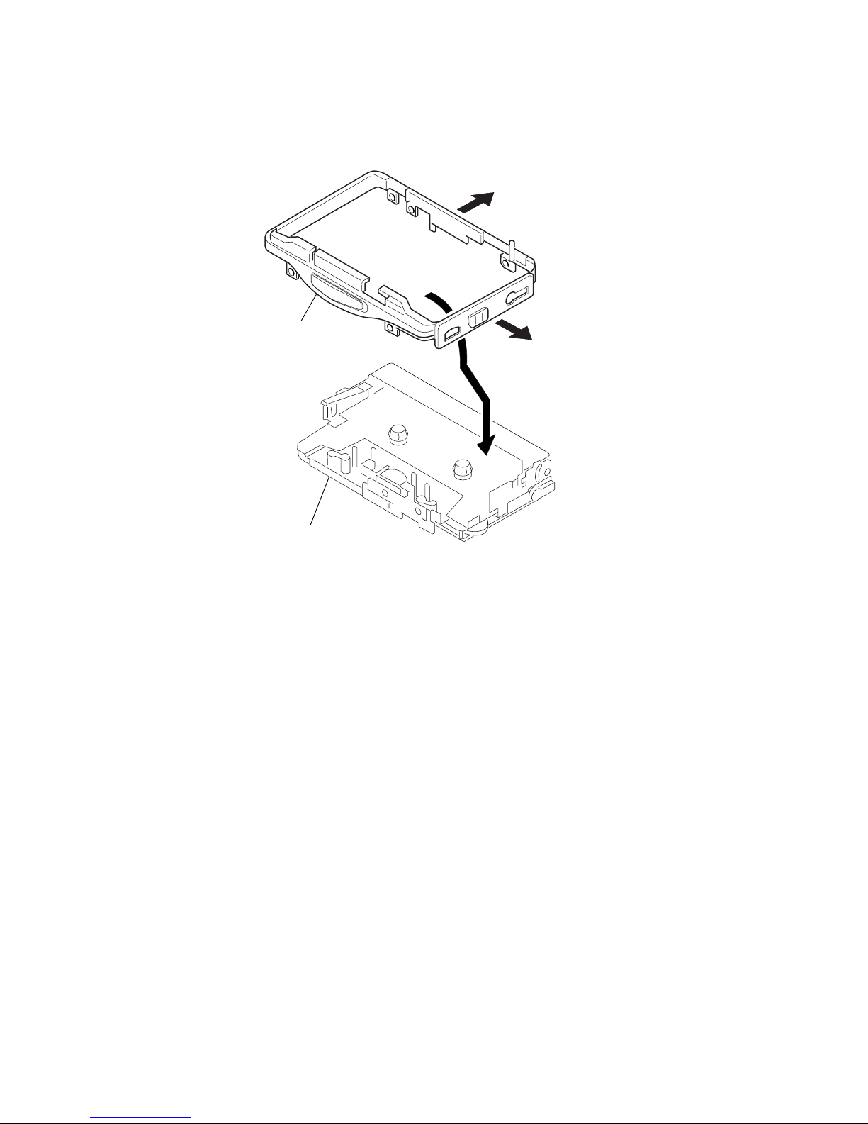
reel ornament
5
tape mechanism deck
3-5. TAPE MECHANISM DECK
– 7 –
PRECAUTION
1. Specified voltage : 1.3V
2. Switch position
MENU button : a NR light off (OFF)
: AVLS light off (OFF)
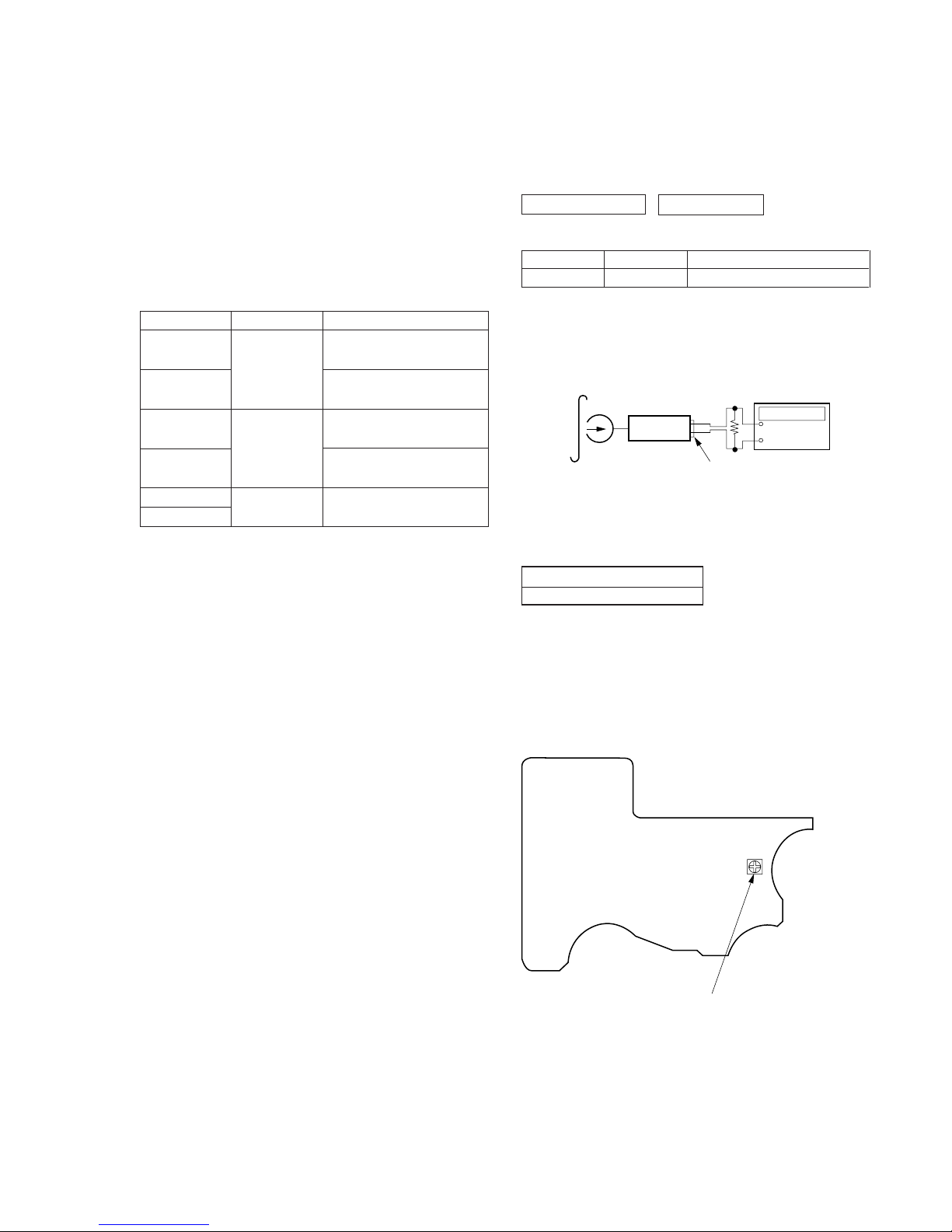
TAPE SECTION 0 dB=0.775 V
Test T ape
Tape Speed Adjustment
Procedure :
1. Playback WS-48A (Tape center part) in the FWD state and
adjust RV601 so that the frequency counter reading becomes
3,000 Hz.
Specification V alue:
Digital frequency counter
2,970 to 3,030 Hz
2. Playback WS-48A (Tape center part) in the REV state.
Check that frequency counter reading is within 60 Hz of the
reading of step1.
Adjustment Location :
[MAIN BOARD] — SIDE A —
Torque meter
CQ-102C
CQ-102RC
CQ-201B
Mode
FWD
FWD
Back Tension
REV
REV
Back Tension
FF
REW
Test tape
WS-48A
(3kHz, 0dB)
set
16
Ω
2
REMOTE jack (J701)
+
–
Frequency counter
RV601 : Tape speed
SECTION 4
MECHANICAL ADJUSTMENTS
PRECAUTION
1. Clean the following parts with a denatured-alcahol-moistened
sweb :
Playback head Pinch roller
Rubber belt Capstan
2. Demagnetize the playback head using a demagnetizer.
3. Do not use a magnetized screwdriver for adjustments.
4. After adjusting, apply screw-locking compound onto the
adjusted parts.
5. Unless specified otherwise, use a specified voltage (1.3V) to
perform the adjustments.
Torque Measurement
Meter reading
20 to 30 g · cm
(0.28 to 0.42 oz · inch)
0.4 to 2.0 g · cm
(0.0056 to 0.028 oz · inch)
20 to 30 g · cm
(0.28 to 0.42 oz · inch)
0.4 to 2.0 g · cm
(0.0056 to 0.028 oz · inch)
More than 40 g · cm
(More than 0.56 oz · inch)
Type
WS-48A
Signal
3kHz, 0dB
Purpose
Tape Speed Adjustment
SECTION 5
ELECTRICAL ADJUSTMENTS
 Loading...