

Page 1
Wireless
Surround Kit
2-895-784-23(1)
Operating Instructions
Mode d’emploi
GBGB
FR
WAHT-SD1
©2007 Sony Corporation
Page 2

3
Table of Contents
About this manual ..........................................2
Unpacking ......................................................3
Hooking Up ....................................................4
Connecting the AC Power Cords (Mains
Leads) .............................................................8
Adjusting the Wireless System ......................8
Installing the IR Transmitter and the IR
Receiver on a Wall .......................................11
Troubleshooting ...........................................13
Specifications ...............................................14
Index to Parts ...............................................15
WARNING
To reduce the risk of fire or electric
shock, do not expose this apparatus to
rain or moisture.
This Class B digital apparatus complies with Canadian
ICES-003.
Do not install the appliance in a confined space, such
as a bookcase or built-in cabinet.
To prevent fire or shock hazard, do not place objects
filled with liquids, such as vases, on the apparatus.
The nameplate is located on the bottom exterior.
Precautions
On power sources
• Install this system so that the AC power cord (mains)
can be unplugged from the wall socket immediately
in the event of trouble.
On placement
• Do not place the system in locations that are hot and
subject to direct sunlight, dusty, very humid, or
extremely cold.
• Use caution when placing the system on a specially
treated (waxed, oiled, polished, etc.) floor, as staining
or discoloration may result.
• Allow adequate air circulation to prevent internal
heat buildup.
• Do not place the system on surfaces (rugs, blankets,
etc.) or near materials (curtains, draperies) that may
block the ventilation slots.
• Do not install the system near heat sources such as
radiators, or air ducts, or in a place subject to direct
sunlight, excessive dust, mechanical vibration, or
shock.
• Do not install the system in an inclined position. It is
designed to be operated in a horizontal position only.
• Position the Sony DVD Home Theatre System
(DAV) and surround amplifier away from each other.
• Keep the system away from equipment with strong
magnets, such as microwave ovens, or large
loudspeakers.
• Do not place heavy objects on the system.
• If you use more than one set of these systems (Sony
DVD Home Theatre System (DAV) and WAHTSD1), position them away from each other to avoid
cross talk.
On cleaning
Clean the cabinets with a soft cloth lightly moistened
with a mild detergent solution or water. Do not use any
type of abrasive pad, scouring powder or solvent such
as alcohol or benzene.
Safety
• If anything falls into the cabinet, unplug the unit and
have it checked by qualified personnel before
operating it any further.
• Unplug the unit from the wall outlet if you do not
intend to use it for an extended period of time. To
disconnect the cord, pull it out by the plug, never by
the cord.
About this manual
The WAHT-SD1 is a Wireless Surround Kit for
the Sony DVD Home Theatre System (DAV).
DAV-DZ555K/DZ556KB model is used in this
manual for some illustrations.
This kit is for models which have a slot cover
and have “DIR-TC1” printed on the rear panel.
GB
2
Page 3
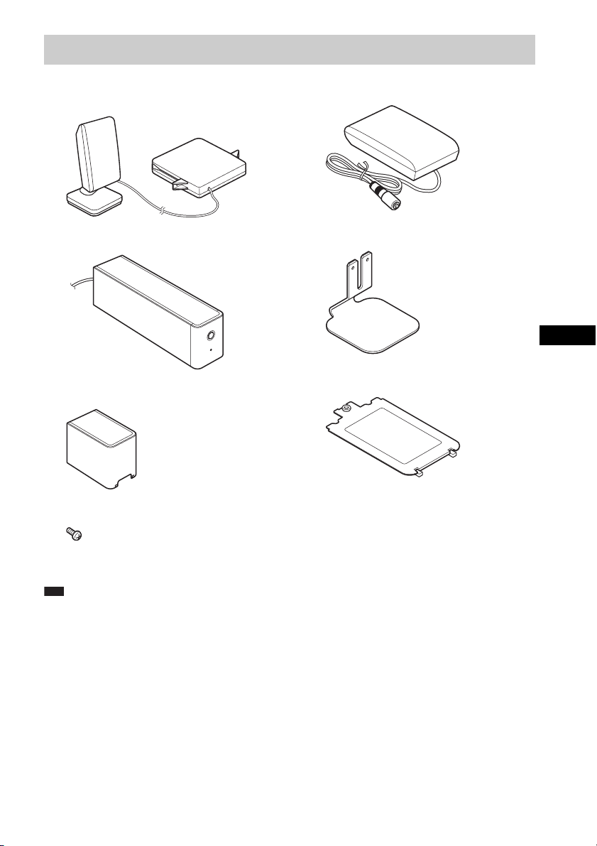
Unpacking
Transmitter (DIR-TC1) (IR transmitter +
Transmitter box) (1)
Surround amplifier (TA-SB500WR) (1)
R
E
W
O
P
E
IN
L
N
/O
R
E
W
O
P
Speaker cord cover (1)
IR receiver (DIR-R1) (1)
IR receiver stand (1)
GBGB
Speaker cord holder (1)
Screw (1)
Operating Instructions (1)
Note
• Speaker cords are not supplied.
GB
3
Page 4
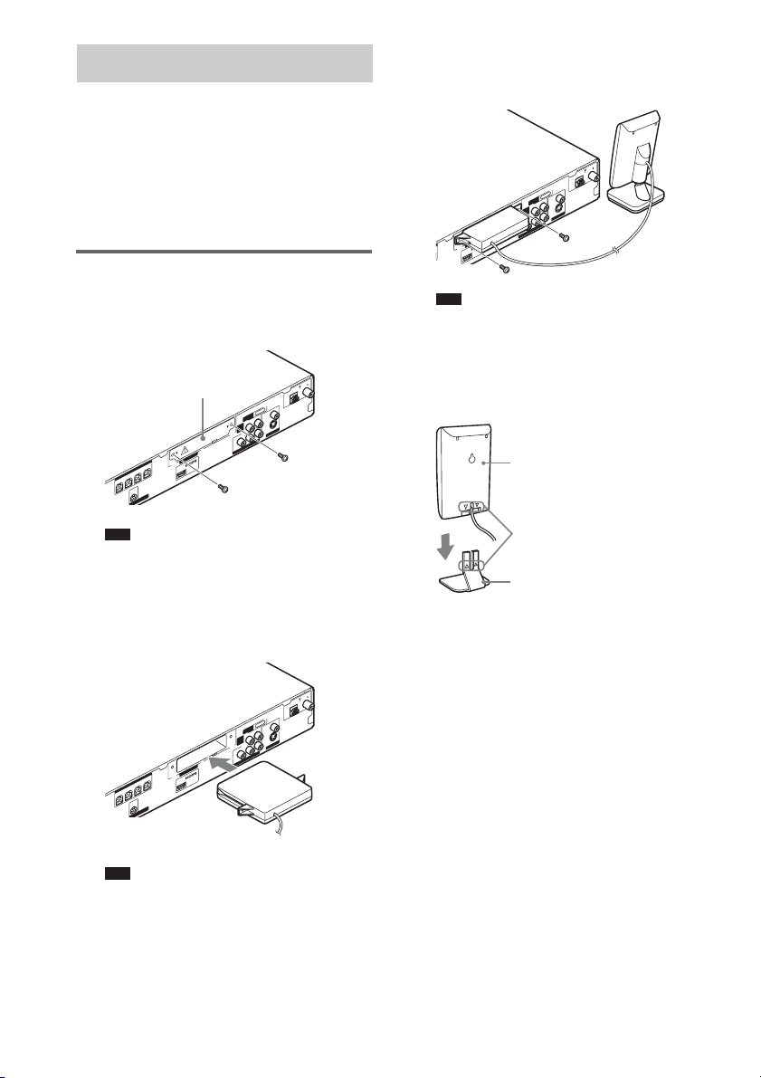
Hooking Up
Connecting the transmitter and the surround
amplifier to a Sony DVD Home Theatre System
(DAV).
Before installing, make sure to
remove the AC power cord (mains
lead) of the system from the wall
outlet (mains).
Inserting the transmitter
1 Remove the screws and detach the slot
cover.
L
IA
X
A
O
C
5
7
M
Slot cover
DMPO
R AUDIO IN L
TV/
VIDEO
)
Y
L
N
O
D
V
D
(
B
/C
B
P
VID
Y
NENT
PO
OM
C
1
-TC
DIR
L
R
U
OUT
S
AKER
SPE
L
T
N
O
R
F
R
T
N
O
R
F
-LIGH
(DVD ONLY)
R
R
U
S
T
T SYNC OU
F
M
A
RT
VIDEO
O
E
T
)
ID
Y
V
L
N
S
O
R OU
D
V
D
(
ITO
ON
M
R
/C
R
P
UT
O
EO
3 Make sure to use the same screws to
secure the transmitter box.
IR transmitter
L
IA
X
A
O
C
5
7
M
F
M
A
RT
DMPO
VIDEO
R AUDIO IN L
TV/
O
E
)
ID
Y
L
V
VIDEO
N
S
O
D
V
D
(
NITOR OUT
)
MO
Y
L
N
O
D
V
R
D
(
/C
R
P
T
U
B
/C
B
P
VIDEO O
ENT
Y
PON
OM
C
1
C
-T
IR
D
OUT
(DVD ONLY)
Note
• Do not use other screws to fasten the transmitter
box.
When using the IR receiver stand, attach the
stand so that both delta marks on the IR receiver
and stand are aligned.
IR receiver
Note
• Remove the screws from the slot cover bearing
the caution mark. Do not remove other screws.
• The slot cover is no longer necessary; however,
keep it after detaching.
2 Insert the transmitter box.
1
-TC
IR
D
L
R
U
OUT
S
R
KE
EA
SP
L
T
N
O
R
F
R
T
N
O
R
F
-LIG
Note
• Insert the transmitter box with the SONY logo
facing up.
GB
4
(DVD ONLY)
R
R
U
S
T
U
O
YNC
T S
H
Delta marks
IR receiver stand
L
IA
X
A
O
C
5
7
M
F
AM
DMPORT
VIDEO
R AUDIO IN L
TV/
O
E
)
ID
Y
UT
V
L
VIDEO
N
S
O
D
V
D
(
)
MONITOR O
Y
L
N
O
D
V
R
D
(
/C
R
P
B
/C
B
P
VIDEO OUT
Y
NENT
COMPO
Page 5
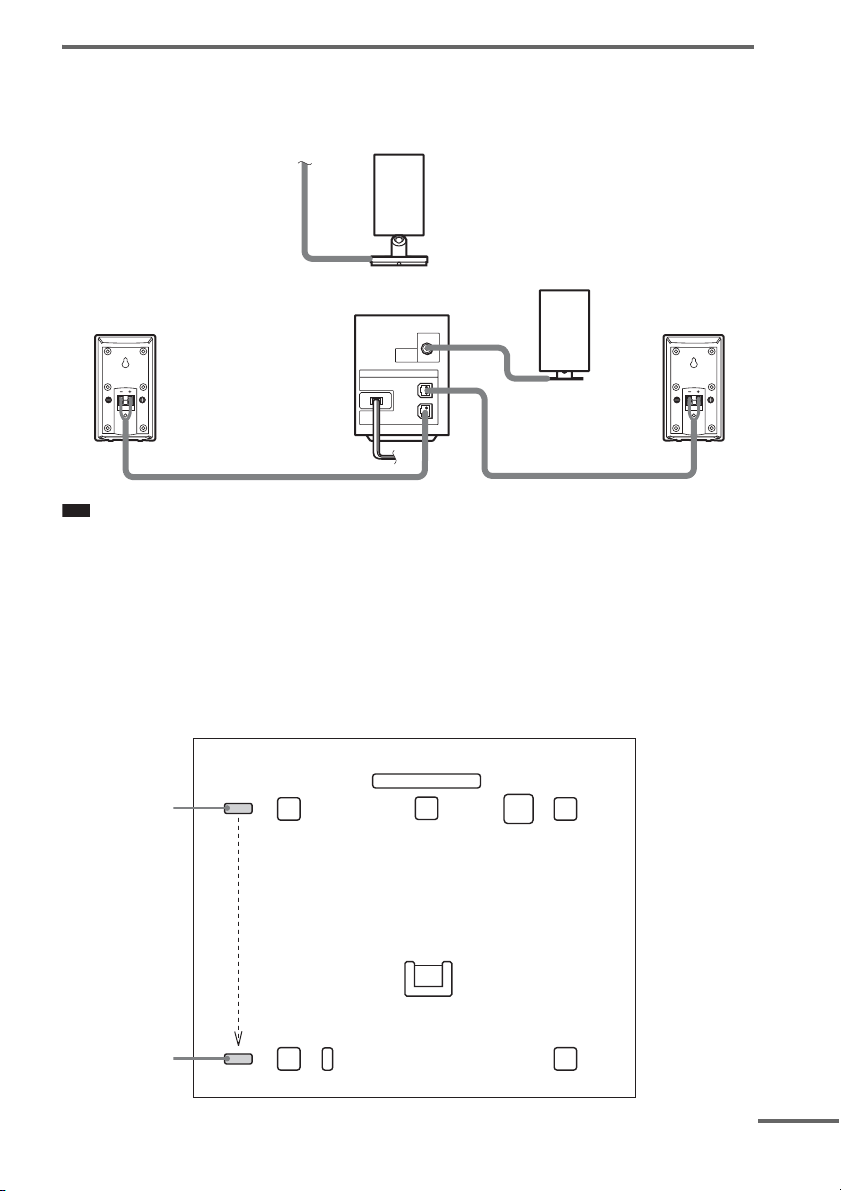
Connecting the Surround Speakers and the IR Receiver
d
Insert the connectors of the speaker cords in their corresponding speaker jacks. The connectors of the
speaker cords are the same color as the jacks to be connected.
IR transmitter
IR receiver
Surround amplifier
DIR-R1
SPEAKER
SURROUND L
SURROUND R
Surround speaker (R)
Note
Surround speaker (L)
• Use the speaker cord supplied with the Sony DVD Home Theatre System (DAV) to connect the surround speakers
to the surround amplifier.
• Customers who already have the Sony DVD Home Theatre System (DAV), use the speaker cords of the system.
• When you use this Wireless Surround Kit, do not connect the speaker cord (s) to the surround speaker jack (s) on
your Sony DVD Home Theatre System (DAV).
• The cord of the IR receiver is for this system only, and is not commercially available.
Example for installation
Position the IR transmitter and IR receiver as illustrated.
Top view
TV
Center speaker
Listening position
Front
speaker (R)
Subwoofer
Surround
speaker (R)
IR transmitter
IR receiver
Front
speaker (L)
Surround
speaker (L)
Surround amplifier
continue
GB
5
Page 6
About the surround amplifier
After connecting, you can attach the cover to the
surround amplifier for organizing and storing
excess speaker cords.
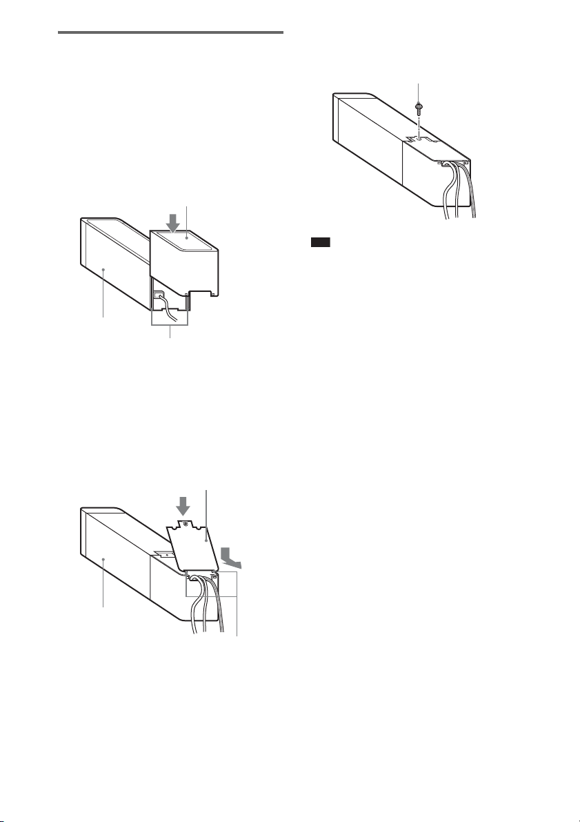
Attaching the cover
1 Attach the speaker cord cover by
sliding it down along the grooves at the
edges of the surround amplifier.
Speaker cord cover
Surround amplifier
Grooves
Push the speaker cord cover down until you
hear a click. Turn the surround amplifier
upside down, then store the cords in the
speaker cord cover.
2 Insert the tabs of the speaker cord
holder in the slots of the speaker cord
cover, and press it into place.
Speaker cord holder
3 Secure the speaker cord holder with
the supplied screw.
Screw
Note
• Do not use the speaker cord cover and holder without
the supplied screw.
• Before detaching the speaker cord cover, first remove
the screw, then the speaker cord holder. Forcing the
speaker cord cover off with the screw in place may
cause damage.
• Gently pull apart the side of the speaker cord cover
when detaching.
Surround amplifier
GB
6
Tabs
Page 7
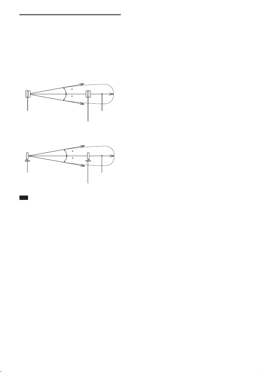
About the wireless system
This wireless system employs the Digital
Infrared Audio Transmission (DIAT) system.
The following diagram indicates the infrared
transmission area (the range that infrared signals
can reach).
Top view
IR transmitter
Side view
IR transmitter
Note
10
10
10
10
Infrared signal
Approx. 10 m
(33 ft)
IR receiver
Infrared signal
Approx. 10 m
(33 ft)
IR receiver
• Do not install the IR receiver in a place exposed to
direct sunlight, or strong light such as an
incandescent lamp.
• Do not use an IR transmitter or IR receiver other than
the one supplied with this system.
GB
7
Page 8
p
Connecting the AC Power Cords (Mains Leads)
Before connecting the AC power cords (mains leads) of your Sony DVD Home Theatre System (DAV)
and the surround amplifier to a wall outlet (mains), connect the front and center speakers to your DAV,
and surround speakers to the surround amplifier.
Adjusting the Wireless System
After connecting the speakers, surround
amplifier, IR transmitter, IR receiver, and the
AC power cords (mains leads), adjust the
wireless system for good transmission.
"/1
POWER
POWER/ON LINE
Indicator
POWER
POWER ON-LINE
1 Press "/1 on DAV and POWER on the
surround amplifier.
The DAV and surround amplifier turn on
and the POWER/ON LINE indicator turns
red.
2 Orient the IR transmitter and IR
receiver to face each other.
Adjust the position until the POWER/ON
LINE indicator turns green.
Ti
• The IR transmitter is movable for easy reorientation.
Note
• Make sure that there is no obstruction such as a
person or object between the IR transm itter and the IR
receiver. Otherwise, the sound from the surround
speakers may be interrupted.
• If the POWER/ON LINE indicator turns red, the
transmission is incomplete. Adjust the position of the
IR transmitter and IR receiver until the POWER/ON
LINE indicator turns green.
• If the POWER/ON LINE indicator flashes in red, the
IR receiver is receiving an infrared signal from
another Sony's wireless product. Move the IR
transmitter and/or the IR receiver so that the
POWER/ON LINE indicator turns green.
GB
8
Page 9
Settings for the Speakers
d
It is necessary to set up your Sony DVD Home
Theatre System (DAV) to use this Wireless
Surround Kit.
1 Press FUNCTION repeatedly until
“DVD” appears in the front panel
display.
2 Press DISPLAY when the system is
in stop mode.
The Control Menu appears.
3 Press X/x to select [SPEAKER
FORMATION], then press .
)
1 ( 4 4
)
3 ( 2 8
T
0 : 0 3 : 0 4
SPEAKER FORMATION
SPEAKER FORMATION
AUTO CALIBRATION
DVD VIDEO
4 Press X/x to select [SPEAKER
FORMATION], then press .
The options for [SPEAKER
FORMATION] appear.
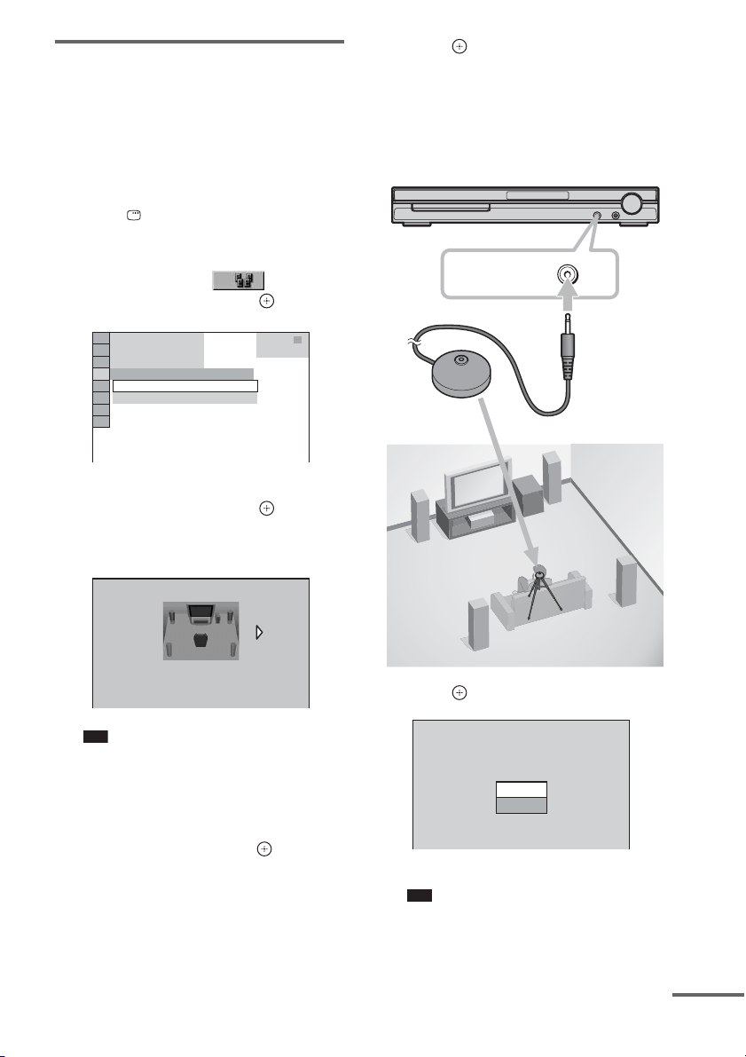
7 Press .
Set up the calibration mic at ear level using
a tripod, etc. (not supplied). The front of
each speaker should face the calibration
mic, and there should be no obstruction
between either speaker and the calibration
mic. Be quiet during the measurement.
A.CAL MIC
Calibration mic
SPEAKER FORMATION
STANDARD(WIRELESS)
Note
• The [STANDARD (WIRELESS)] option
appears after inserting transmitter box. (When
you do not insert transmitter box, only
[STANDARD] appears.)
5 Press C/c to select [STANDARD
(WIRELESS)], then press .
6 Connect the calibration mic to the
A.CAL MIC jack on the front panel and
press X/x to select [YES].
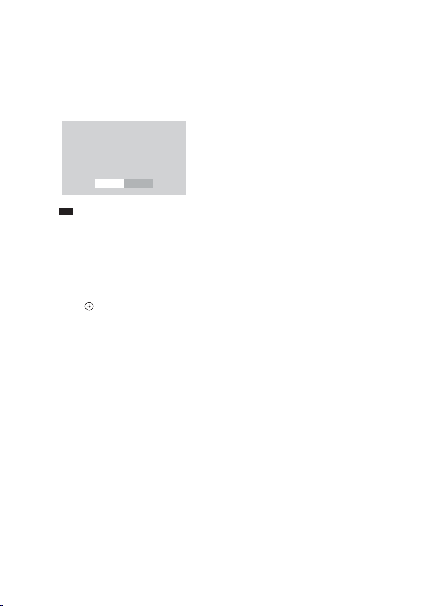
8 Press .
AUTO CALIBRATION
Connect calibration mic. Start
measurement?
YES
NO
Auto Calibration starts.
Note
• Loud test sound is output when [AUTO
CALIBRATION] starts. You cannot turn the
volume down. Give consideration to children
and neighbors.
continue
GB
9
Page 10
• Avoid being in the measurement area and
making noise during the measurement (which
takes about 3 minutes), as it may interfere with
measurement.
9 Unplug the calibration mic and press C/
c to select [YES].
Quick Setup is finished. All connections
and setup operations are complete.
Measurement complete.
FRONT L :
FRONT R :
CENTER :
SUBWOOFER :
SURROUND L :
SURROUND R :
If OK, unplug calibration mic and select
“YES”.
Note
• Reflections from walls or the floor may affect
measurements.
• If measurement fails, follow the message then
retry [AUTO CALIBRATION].
• When you select [SECOND ROOM] for
[SPEAKER FORMATION], the measurement
of [SURROUND L] and [SURROUND R] are
not displayed.
YES
YES
YES
NONE
YES
NONE
NONE
NO
10Press .
10
GB
Page 11

p
Installing the IR
d
Transmitter and the IR
Receiver on a Wall
You can hang the IR transmitter and IR receiver
on a wall when:
– there is an obstruction between the IR
transmitter and the IR receiver.
– people often pass between the IR transmitter
and the IR receiver.
When hanging both the IR transmitter and IR
receiver, adjust the position of the IR transmitter
after deciding the position of the IR receiver.
3 Hang the IR transmitter by the hole on
the bottom of the stand on the screw.
Make sure that the IR transmitter does not
move after installation.
IR transmitter
Stand
Installing the IR transmitter
on a wall
1 Rotate the stand of the IR transmitter.
IR transmitter
Stand
2 Install 2 commercially available screws
in the wall so as to protrude 4 mm (
inch).
Install the screws 30 mm (1
apart.
30 mm (1 3/16 inches)
5 to 7 mm
(7/32 to 9/32 inch)
3
/16 inches)
3
/16
Ti
• You can store the cords in the troughs in the bottom
of the stand.
Stand
Troughs
Note
• Use screws suitable for the material and strength of
the wall.
• Do not install the IR transmitter on a wall of low
strength.
• Sony is not l iable for any damage or accident incurred
by incorrect installation (i.e. low strength wall, etc.),
incorrect use of this product, or natural disaster.
• When connecting/disconnecting the cord, detach the
IR transmitter from the wall first.
4 mm
(3/16 inch)
continue
11
GB
Page 12

Installing the IR receiver on a
p
wall
1 Install a commercially available screw
in the wall so as to protrude 4 mm (
inch).
5 to 7 mm
(7/32 to 9/32 inch)
4 mm
(3/16 inch)
3
/16
2 Detach the IR receiver stand and hang
it by the hole on the rear of the IR
receiver on the screw.
Make sure that the IR receiver does not
move after installation.
IR receiver
IR receiver stand
Ti
• When reattaching the IR receiver stand to the IR
receiver, attach the stand so that both delta marks on
the IR receiver and stand are aligned.
GB
12
Page 13

Troubleshooting
If you experience any of the following
difficulties while using the system, use this
troubleshooting guide to help remedy the
problem before requesting repairs. Should any
problem persist, consult your nearest Sony
dealer.
Note that if service personnel changes some
parts during repair, these parts may be retained.
In the event of a problem with the surround
amplifier, have a Sony dealer check the entire
system together (system, and surround speaker).
Power
The power is not turned on.
• Check that the AC power cord (mains lead) is
connected securely.
The POWER/ON LINE indicator does not turn
on.
• The + and – speaker cords are short-circuited. In
this case, disconnect the AC power cord (mains
lead) of the surround amplifier from the wall
outlet (mains), reconnect, and then turn the
surround amplifier on.
Sound
There is no sound.
• The speaker cord is not connected securely.
• Check the speaker settings.
The left and right sounds are unbalanced or
reversed.
• Check that the speakers and components are
connected correctly and securely.
• Check the unit's SYSTEM MENU and select
"REV OFF" when "SR SL REV" is set to "REV
ON".
Severe hum or noise is heard.
• Check that the speakers and components are
connected securely.
• Check that the connecting cords are away from a
transformer or motor, and at least 3 meters (10 ft)
away from your TV set or a fluorescent light.
• Move your TV away from the audio components.
• The plugs and jacks are dirty. Wipe them with a
cloth slightly moistened with alcohol.
• Clean the disc.
No sound or only a very low-level sound is
heard from the surround speakers.
• Check the speaker connections and settings.
• Make sure the sound field function is on.
• Depending on the source, the effect of the
surround speakers may be less noticeable.
• Wireless setting of the surround speaker is not
correct.
• The plasma display may interfere with
transmission, in which case, adjust the position of
the IR transmitter and IR receiver.
• Do not install the IR transmitter, IR receiver in a
place exposed to direct sunlight or strong light
such as an incandescent lamp.
• Do not use the IR transmitter and the IR Receiver
near a radiant heater or fireplace.
• Clean the surface of the IR transmitter and IR
receiver.
• A 2 channel source is being played.
Operation
The POWER/ON LINE indicator momentarily
turns red.
• When changing the disc or switching the function,
the POWER/ON LINE indicator may
momentarily turn red. This is not a malfunction.
The POWER/ON LINE indicator flashes in red.
• The IR receiver is receiving an infrared signal
from another Sony's wireless product. Move the
IR transmitter and/or the IR receiver so that the
POWER/ON LINE indicator turns green.
• Move the wireless system away from any other
nearby wireless system(s).
• Point the IR transmitter at the IR receiver.
The system does not work normally.
• Disconnect the AC power cord (mains lead) from
the wall outlet (mains), then reconnect after
several minutes.
13
GB
Page 14

Specifications
TA-SB500WR (Surround Amplifier)
Amplifier section
Stereo mode (rated)
Surround mode (reference) RMS output power
* Depending on the sound field setting and the source,
there may be no sound output.
Power requirements:
North American models: 120 V AC, 60 Hz
Mexican models: 120 V AC, 60 Hz
Latin American models: 110 – 240 V AC, 50/60 Hz
Taiwan models: 120 V AC, 50/60 Hz
Other models: 220 – 240 V AC, 50/60 Hz
Power consumption On: 40 W
Dimensions (approx.) 65 × 89 × 253 mm
Mass (approx.) 1.3 kg (2 lb 14 oz)
80 W + 80 W
(at 3 ohms, 1 kHz, 1 %
THD)
SL/SR* : 100 W
(per channel at 3 ohms, 1
kHz, 10 % THD)
5
/8 × 3 5/8 × 10 inches)
(2
(w/h/d)
65 × 89 × 345 mm
5
(2
/8 × 3 5/8 × 13 5/8 inches)
(w/h/d) incl. speaker cord
cover
1.4 kg (3 lb 2 oz) incl.
speaker cord cover
Transmitter box
Dimensions (approx.) 108 × 17 × 80 mm
Mass (approx.) 0.07 kg (
3
/8 × 11/16 × 3 1/4 inches)
(4
(w/h/d)
5
/32 lb)
Design and specifications are subject to change
without notice.
DIR-R1 (IR receiver)
Dimensions (approx.) 50 × 83 × 21 mm
(2 × 3
(w/h/d)
50 × 92 × 42 mm
(2 × 3
(w/h/d) with stand
Mass (approx.) 0.05 kg (
0.07 kg (
DIR-TC1
IR transmitter
Dimensions (approx.) 58 × 112 × 58 mm
(2
(w/h/d)
Mass (approx.) 0.14 kg (
GB
14
3
/8 × 27/32 inches)
5
/8 × 1 11/16 inches)
1
/8 lb)
5
/32 lb) with stand
3
/8 × 4 1/2 × 2 3/8 inches)
5
/16 lb)
Page 15

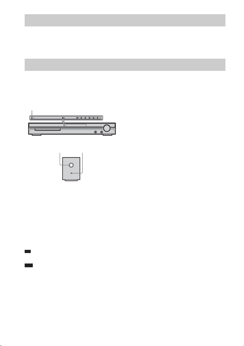
Index to Parts
Surround amplifier
Front panel
POWER
POWER ON-LINE
A POWER (ON/OFF)
B POWER/ON LINE indicator
C DIR-R1 jack
D SURROUND L SPEAKER jack
E SURROUND R SPEAKER jack
Rear panel
DIR-R1
SPEAKER
SURROUND L
SURROUND R
15
GB
Page 16

3
Table des matières
A propos de ce mode d’emploi ......................2
Déballage .......................................................3
Raccordements ...............................................4
Raccordement des cordons d’alimentation
(cordons secteur) ............................................8
Réglage du système sans fil ...........................8
Fixation murale de l’émetteur IR et du
récepteur IR ..................................................11
Dépannage ...................................................13
Spécifications ...............................................14
Schémas de connexion .................................15
AVERTISSEMENT
Pour réduire les risques d’incendie ou
d’électrocution, gardez cet appareil à
l’abri de la pluie et de l’humidité.
Cet appareil numérique de la classe B est conforme à la
norme NMB-003 du Canada.
N’installez pas l’appareil dans un espace confine
comme dans une bibliothèque ou un meuble encastré.
Pour prévenir tout risque d’incendie ou
d’électrocution, ne placez pas d’objets remplis de
liquides, comme des vases, sur l’appareil.
La plaque signalétique est située sur la partie externe,
sur le dessous de l’appareil.
Précautions
Alimentation
• Installez le système de façon à pouvoir débrancher
immédiatement le cordon d’alimentation (cordon
secteur) de la prise murale en cas de problème.
Installation
• Evitez d’installer le système dans un endroit trop
chaud ou trop froid, ou exposé à la lumière directe du
soleil, à la poussière ou à l’humidité.
• Faites attention lorsque vous installez le système sur
un plancher traité (ciré, encaustiqué, poli, etc.), car
cela peut provoquer une décoloration ou des taches.
• Prévoyez une circulation d’air suffisante de manière
à éviter toute surchauffe interne.
• Ne placez pas le système sur une surface moelleuse
(comme un tapis, une couverture, etc.) ou près de
tissus (comme un rideau ou une tenture) risquant
d’obstruer les fentes d’aération.
• N’installez pas le système à proximité de sources de
chaleur telles que des radiateurs ou des conduites
d’air chaud, ni à des endroits exposés à la lumière
directe du soleil, à une poussière excessive, à des
vibrations mécaniques ou à des chocs.
• N’installez pas le système en position inclinée. Ce
système est conçu pour fonctionner uniquement à
l’horizontale.
• Eloignez l’un de l’autre le système DVD Home
Theatre Sony (DAV) et l’amplificateur surround lors
de l’installation.
• Gardez le système à l’écart de tout équipement
contenant des aimants puissants, par exemple des
fours à micro-ondes ou de puissants haut-parleurs.
• Ne posez pas d’objets lourds sur le système.
• Si vous utilisez plusieurs de ces systèmes (système
DVD Home Theatre Sony (DAV) et WAHT-SD1),
éloignez-les les uns des autres afin d’éviter toute
diaphonie.
Entretien
Nettoyez le boîtier à l’aide d’un chiffon doux
légèrement imprégné d’une solution détergente neutre
ou d’eau. N’utilisez pas de t ampons abrasifs, de poudre
à récurer ou de solvant tel que l’alcool ou le benzène.
Sécurité
• Si un obje t ou du liquide venait à pénétrer à l’intérieur
du boîtier, débranchez l’appareil et faites-le vérifier
par un personnel qualifié avant de le remettre en
marche.
• Débranchez l’appareil de la prise murale si vous
prévoyez de ne pas l’utiliser pendant une période
prolongée. Pour débrancher le cordon, tirez sur la
fiche, mais ne tirez jamais sur le cordon proprement
dit.
A propos de ce mode
d’emploi
Le WAHT-SD1 est un kit Wi-Fi surround pour
la chaîne DVD Home Theatre Sony (DAV).
Certaines illustrations de ce manuel sont tirées
du modèle DAV-DZ555K/DZ556KB.
Ce kit est destiné aux modèles munis d’un
cache-connecteur et dont le code « DIR-TC1 »
est apposé sur le panneau arrière.
FR
2
Page 17

Déballage
Emetteur (DIR-TC1) (émetteur IR + boîtier
émetteur) (1)
Amplificateur surround (TA-SB500WR) (1)
R
E
W
O
P
E
IN
L
N
/O
R
E
W
O
P
Cache du cordon d’enceinte (1)
Récepteur IR (DIR-R1) (1)
Support du récepteur IR (1)
Support du cordon d’enceinte (1)
FR
Vis (1)
Mode d’emploi (1)
Remarque
• Les cordons d’enceinte ne sont pas fournis.
FR
3
Page 18

Raccordements
Raccordement de l’émetteur et de
l’amplificateur surround à un système DVD
Home Theatre Sony (DAV).
Avant de procéder à l’installation,
assurez-vous d’avoir débrancher le
cordon d’alimentation (cordon
secteur) du système au niveau de
la prise murale (prise secteur).
3 Veillez à utiliser les mêmes vis pour
fixer le boîtier émetteur.
Emetteur IR
L
IA
X
A
O
C
5
7
M
F
M
A
RT
DMPO
VIDEO
R AUDIO IN L
TV/
O
E
)
ID
Y
L
V
VIDEO
N
S
O
D
V
D
(
NITOR OUT
)
MO
Y
L
N
O
D
V
R
D
(
/C
R
P
T
U
B
/C
B
P
VIDEO O
ENT
Y
PON
OM
C
1
C
-T
IR
D
OUT
(DVD ONLY)
Insertion de l’émetteur
1 Retirez les vis et enlevez le volet de la
fente d’insertion.
R
KE
R
PEA
R
U
S
S
L
T
N
O
R
F
R
T
N
O
R
F
YNC
S
HT
-LIG
Remarque
Volet de la fente
d’insertion
1
-TC
IR
D
L
R
U
OUT
S
(DVD ONLY)
T
U
O
PORT
DM
R AUDIO IN L
TV/
VIDEO
)
Y
L
N
O
D
V
D
(
/C
R
P
B
/C
B
P
VIDEO OU
ENT
Y
MPON
CO
L
IA
X
A
O
C
5
7
M
F
AM
VIDEO
O
E
)
ID
Y
UT
V
L
N
S
O
O
D
V
D
(
NITOR
MO
R
T
• Retirez les vis du volet de la fente d’insertion en
respectant le symbole d’avertissement. Ne
retirez pas d’autres vis.
• Le volet de la fente d’insertion n’est plus
nécessaire ; cependant, conservez-le après
l’avoir retiré.
2 Insérez le boîtier émetteur.
L
IA
X
A
O
C
5
7
M
F
AM
PORT
DM
VIDEO
R AUDIO IN L
TV/
O
E
T
)
ID
Y
L
V
VIDEO
N
S
O
R OU
D
V
D
(
ONITO
)
M
Y
L
N
O
D
V
R
D
(
/C
R
P
T
OU
B
/C
B
P
VIDEO
Y
PONENT
OM
C
1
-TC
IR
D
L
R
U
OUT
S
R
KE
EA
SP
L
T
N
O
R
F
R
T
N
O
R
F
-LIG
(DVD ONLY)
R
R
U
S
T
U
O
YNC
S
T
H
Remarque
• N’utilisez pas d’autres vis pour fixer le boîtier
émetteur.
Lorsque vous utilisez le support du récepteur IR,
fixez le support en alignant ses deux repères
triangulaires sur ceux du récepteur IR.
Récepteur IR
Repères triangulaires
Support du récepteur IR
Remarque
• Insérez le boîtier émetteur avec le logo SONY
vers le haut.
FR
4
Page 19

Raccordement des enceintes surround et du récepteur IR
Insérez les connecteurs des cordons d’enceinte aux prises enceinte correspondantes. Les connecteurs
des cordons d’enceinte sont de la même couleur que les prises à raccorder.
Emetteur IR
Récepteur IR
Amplificateur surround
DIR-R1
SPEAKER
SURROUND L
SURROUND R
Enceinte surround (D)
Remarque
Enceinte surround (G)
• Utilisez le cordon d’enceinte fourni avec le système DVD Home Theatre Sony (DAV) pour raccorder les enceintes
surround à l’amplificateur surround.
• Les utilisateurs qui possèdent déjà le système DVD Home Theatre Sony (DAV) doivent utiliser les cordons
d’enceinte du système.
• Lorsque vous utilisez ce kit Wi-Fi surround, ne raccordez pas les cordons d’enceinte aux prises de l’enceinte
surround de votre chaîne DVD Home Theatre Sony (DAV).
• Le cordon du récepteur IR est uniquement destiné à ce système et n’est pas disponible dans le commerce.
Exemple d’installation
Positionnez l’émetteur IR et le récepteur IR comme illustré dans le schéma ci-dessous.
Vue du haut
Téléviseur
Enceinte centrale
Position d’écoute
Enceinte
avant (D)
Caisson de
graves
Enceinte
surround (D)
Emetteur IR
Récepteur IR
Enceinte
avant (G)
Enceinte
surround (G)
Amplificateur surround
suite
FR
5
Page 20

A propos de l’amplificateur
surround
Une fois la connexion terminée, vous pouvez
fixer le volet de l’amplificateur surround pour
disposer et ranger les cordons d’enceinte.
Fixation du cache
1 Fixez le cache du cordon d’enceinte en
le faisant glisser le long des rainures
de l’amplificateur surround.
Cache du cordon
d’enceinte
Amplificateur
surround
Rainures
Faites glisser le cache du cordon d’enceinte
vers le bas jusqu’à ce qu’il émette un déclic.
Retournez l’amplificateur surround, puis
rangez les cordons dans le cache du cordon
d’enceinte.
2 Insérez les languettes du support du
cordon d’enceinte dans les fentes du
cache du cordon d’enceinte, puis
appuyez dessus pour le fixer.
Support du cordon
d’enceinte
3 Fixez le support du cordon d’enceinte à
l’aide de la vis fournie.
Vis
Remarque
• N’utilisez pas le cache ou le support du cordon
d’enceinte sans la vis fournie.
• Avant d’enlever le cache du cordon d’enceinte,
retirez tout d’abord la vis, puis le support du cordon
d’enceinte. Ne forcez pas sur le cache du cordon
d’enceinte sans avoir préalablement retiré la vis, car
vous pourriez endommager le cache.
• Lorsque vous retirez le cache du cordon d’enceinte,
faites-le glisser sans forcer.
6
Amplificateur
surround
Languettes
FR
Page 21

A propos du système sans fil
Ce système sans fil utilise la transmission audio
numérique à infrarouge (DIAT). Le schéma
suivant indique la zone d’émission infrarouge
(la portée des signaux infrarouges).
Vue du haut
Emetteur IR
Vue latérale
Emetteur IR
Remarque
Signal infrarouge
10
10
Environ 10 m
(33 pieds)
Récepteur IR
Signal infrarouge
10
10
Environ 10 m
(33 pieds)
Récepteur IR
• N’installez pa s le récepteur IR dans un endroit exposé
aux rayons directs du soleil ou à une lumière intense,
notamment une lampe à incandescence.
• N’utilisez pas un émetteur IR ou un récepteur IR autre
que celui fourni avec ce système.
FR
7
Page 22

Raccordement des cordons d’alimentation (cordons
secteur)
Avant de raccorder les cordons d’alimentation (cordons secteur) de votre système DVD Home Theatre
Sony (DAV) ainsi que l’amplificateur surround à une prise murale (secteur), raccordez les enceintes
avant et centrale de votre système DAV, puis les enceintes surround à l’amplificateur surround.
Réglage du système sans fil
Après avoir raccordé les enceintes,
l’amplificateur surround, l’émetteur IR, le
récepteur IR et les cordons d’alimentation,
réglez le système sans fil pour obtenir une bonne
transmission des signaux.
"/1
POWER
Témoin
POWER/ON LINE
POWER
POWER ON-LINE
1 Appuyez sur la touche "/1 du système
DAV et sur la touche POWER de
l’amplificateur surround.
Le système DAV et l’amplificateur
surround s’allument tandis que le témoin
POWER/ON LINE vire au rouge.
2 Orientez l’un vers l’autre l’émetteur IR
et le récepteur IR.
Réglez la position jusqu’à ce que le témoin
POWER/ON LINE vire au vert.
Conseil
• L’émetteur IR est facilement orientable.
Remarque
• Assurez-vous qu’aucun obstacle (une personne ou un
objet) ne se trouve entre l’émetteur IR et le récepteur
IR. Cela risquerait en effet d’interrompre la diffusion
du son par les enceintes surround.
• Si le témoin POWER/ON LINE vire au rouge, la
transmission est incomplète. Réglez la position de
l’émetteur IR et du récepteur IR jusqu’à ce que le
témoin POWER/ON LINE vire au vert.
• Si le témoin POWER/ON LINE clignote en rouge, le
récepteur IR reçoit un signal infrarouge provenant
d’un autre produit sans fil Sony. Déplacez l’émetteur
IR et/ou le récepteur IR afin que le témoin POWER/
ON LINE vire au vert.
FR
8
Page 23

Réglages des enceintes
Pour pouvoir utiliser ce kit surround sans fil,
vous devez configurer votre système DVD
Home Theatre Sony (DAV).
1 Appuyez plusieurs fois sur FUNCTION
jusqu’à ce que l’indication « DVD »
apparaisse sur l’affichage du panneau
frontal.
2 Appuyez sur DISPLAY quand le
système est en mode d’arrêt.
Le menu de commande apparaît.
3 Appuyez sur X/x pour sélectionner
[DISPOSITION DES H-P], puis
appuyez sur .
6 Raccordez le micro d’étalonnage à la
prise A.CAL MIC du panneau frontal,
puis appuyez sur X/x pour
sélectionner [OUI].
7 Appuyez sur .
Placez le micro d’étalonnage à hauteur
d’oreille à l’aide d’un trépied (non fourni),
par exemple. La face avant de chaque
enceinte doit être dirigée vers le micro
d’étalonnage et il ne doit y avoir aucun
obstacle entre eux. Ne faites pas de bruit
pendant la mesure.
)
1 ( 4 4
)
3 ( 2 8
T
0 : 0 3 : 0 4
DISPOSITION DES H-P
DISPOSITION DES H-P
ETALONNAGE AUTO
DVD VIDEO
4 Appuyez sur X/x pour sélectionner
[DISPOSITION DES H-P], puis appuyez
sur .
Les options de [DISPOSITION DES H-P]
apparaissent.
DISPOSITION DES H-P
STANDARD (SANS FIL)
Remarque
• L’option [STANDARD (SANS FIL)] apparaît
une fois le boîtier émetteur inséré. (Si vous
n’insérez pas le boîtier émetteur, seule l’option
[STANDARD] s’affiche.)
5 Appuyez sur C/c pour sélectionner
[STANDARD (SANS FIL)], puis appuyez
sur .
A.CAL MIC
Micro d’étalonnage
8 Appuyez sur .
ETALONNAGE AUTO
Raccordez le micro d'étalonnage.
Commencer la mesure ?
OUI
NON
L’étalonnage automatique commence.
suite
FR
9
Page 24

Remarque
• Le démarrage de l’[ETALONNAGE AUTO]
entraîne l’émission d’un son de test puissant. Il
n’est pas possible de diminuer le volume.
Pensez aux enfants et à vos voisins !
• Évitez de vous placez dans la zone de mesure et
de faire du bruit lors de la mesure (qui prend
environ 3 minutes), car cela pourrait provoquer
des interférences.
9 Débranchez le micro d’étalonnage et
appuyez sur C/c pour sélectionner
[OUI].
L’Installation rapide est terminée. Vous
avez effectué tous les raccordements et
toutes les opérations d’installation.
Mesure terminée.
AVANT G :
AVANT D :
CENTRE :
EXTR. GRAVES :
SURROUND G :
SURROUND D :
Si OK, débranchez le micro d'étalonnage et
sélectionnez “OUI”.
Remarque
OUI
OUI
NEANT
OUI
NEANT
NEANT
OUI NON
• Les réflexions sur les murs ou le sol peuvent
affecter les mesures.
• En cas d’échec des mesures, suivez le message
et recommencez l’[ETALONNAGE AUTO].
• Lorsque vous sélectionnez [DEUXIEME
PIECE] pour [DISPOSITION DES H-P], la
mesure des enceintes [SURROUND G] et
[SURROUND D] n’est pas affichée.
10Appuyez sur .
10
FR
Page 25

Fixation murale de
l’émetteur IR et du
récepteur IR
Vous pouvez accrocher l’émetteur IR et le
récepteur IR sur un mur dans les cas suivants :
– Présence d’un obstacle entre l’émetteur IR et
le récepteur IR.
– Passages fréquents entre l’émetteur IR et le
récepteur IR.
Si vous accrochez l’émetteur IR et le récepteur
IR, réglez la position de l’émetteur IR après
avoir déterminé celle du récepteur IR.
Fixation murale de l’émetteur
IR
1 Faites pivoter le support de l’émetteur
IR.
Emetteur IR
3 Accrochez l’émetteur IR à la vis à l’aide
de l’orifice situé sur le dessous du
support.
Une fois l’émetteur IR installé, assurezvous qu’il demeure bien immobile.
Emetteur IR
Support
Conseil
• Vous pouvez ranger les cordons dans la goulotte
située sur le dessous du support.
Support
Support
2 Fixez au mur 2 vis achetées dans le
commerce et laissez-les dépasser de
3
/16 pouce).
4mm (
Laissez 30 mm (1
vis.
5 à 7 mm
7
/32 à 9/32
(
3
(
3
/16 pouce) entre chaque
30 mm (1 3/16 pouce)
pouce
)
4mm
/16
pouce
)
Goulotte
Remarque
• Utilisez des vis adaptées au matériau et à la résistance
du mur.
• N’installez pas l’émetteur IR sur un mur peu solide.
• Sony n’assume aucune responsabilité en cas de
dégâts ou d’accidents consécutifs à une installation
incorrecte (mur trop fragile, par exemple), d’un
mauvais usage de ce produit ou d’une catastrophe
naturelle.
• Lorsque vous branchez/débranchez le cordon, veillez
tout d’abord à décrocher du mur l’émetteur IR.
suite
11
FR
Page 26

Fixation murale du récepteur
IR
1 Fixez au mur une vis achetée dans le
commerce et laissez-la dépasser de
3
4 mm (
/16 pouce).
5 à 7 mm
7
/32 à 9/32 pouce)
(
4mm
(3/16 pouce)
2 Détachez le support du récepteur IR et
accrochez le récepteur à la vis par
l’orifice situé à l’arrière de celui-ci.
Une fois le récepteur IR installé, assurezvous qu’il demeure bien immobile.
Récepteur IR
Support du récepteur IR
Conseil
• Lorsque vous refixez le support du récepteur IR,
veillez à ce que les deux repères triangulaires du
support et du récepteur IR soient alignés.
FR
12
Page 27

Dépannage
Si vous rencontrez l’une des difficultés
suivantes lors de l’utilisation de ce système,
consultez ce guide de dépannage pour tenter de
remédier au problème. Si le problème persiste,
consultez votre revendeur Sony le plus proche.
Notez que si le technicien remplace des pièces
au cours d’une réparation, elles ne vous sont pas
nécessairement rendues.
En cas de problème avec l’amplificateur
surround, demandez à un revendeur Sony de
vérifier le bon fonctionnement de l’intégralité du
système (système proprement dit et enceinte
surround).
Alimentation
Le système ne se met pas sous tension.
• Vérifiez que le cordon d’alimentation est
correctement raccordé.
Le témoin POWER/ON LINE ne s’allume pas.
• Les cordons + et – des enceintes sont courtcircuités. Dans ce cas, débranchez le cordon
d’alimentation (cordo n secteur) de l’amplificateur
surround au niveau de la prise murale (prise
secteur), puis mettez l’amplificateur surround
sous tension.
Son
Il n’y a pas de son.
• Le cordon d’enceinte n’est pas raccordé
correctement.
• Vérifiez les réglages des enceintes.
Les sons gauche et droit ne sont pas
équilibrés ou sont inversés.
• Vérifiez que les enceintes et les composants sont
raccordés correctement.
• Vérifiez le SYSTEM MENU de l’unité, puis
sélectionnez « REV OFF » si « SR SL REV » est
réglé sur « REV ON ».
Le son est parasité par un bourdonnement ou
des interférences sont émises.
• Vérifiez que les enceintes et les composants sont
raccordés correctement.
• Vérifiez que les cordons de connexion ne sont pas
placés près d’un transformateur ou d’un moteur et
à au moins 3 mètres (10 pieds) de votre téléviseur
ou d’une lumière fluorescente.
• Eloignez votre téléviseur des autres composants.
• Les fiches et les prises sont sales. Essuyez-les
avec un chiffon légèrement imbibé d’alcool.
• Nettoyez le disque.
Aucun son ou un son très faible uniquement
est diffusé par les enceintes surround.
• Vérifiez les raccordements et les réglages de
l’enceinte.
• Vérifiez que la fonction de champ acoustique est
activée.
• Selon la source, l’effet des enceintes surround
peut être atténué.
• Le réglage sans fil de l’enc einte surround n’est pas
correct.
• L’écran plasma peut gêner la transmission. Le cas
échéant, réglez la position de l’émetteur IR et du
récepteur IR.
• N’installez pas l’émetteur IR ou le récepteur IR
dans un endroit exposé aux rayons directs du
soleil ou à une lumière intense, notamment une
lampe à incandescence.
• N’utilisez pas l’émetteur IR et le récepteur IR à
proximité d’un radiateur ou d’une cheminée.
• Nettoyez la surface de l’émetteur IR et du
récepteur IR.
• Une source à 2 canaux est en cours de lecture.
Utilisation
Le témoin POWER/ON LINE vire
momentanément au rouge.
• Lorsque vous changez de disque ou lorsque vous
commutez une fonction, il est possible que le
témoin POWER/ON LINE vire momentanément
au rouge. Il ne s’agit pas d’un dysfonctionnement.
Le témoin POWER/ON LINE clignote en rouge.
• Le récepteur IR reçoit un signal infrarouge
provenant d’un autre produit sans fil Sony.
Déplacez l’émetteur IR et/ou le récepteur IR afin
que le témoin POWER/ON LINE vire au vert.
• Eloignez le système sans fil de tous les autres
systèmes sans fil avoisinants.
• Dirigez l’émetteur IR vers le récepteur IR.
Le système ne fonctionne pas normalement.
• Débranchez le cordon d’alimentation (cordon
secteur) au niveau de la prise murale (prise
secteur), puis rebranchez-l e quelques minutes plus
tard.
13
FR
Page 28

Spécifications
TA-SB500WR (Amplificateur surround)
Partie amplificateur
Mode stéréo (nominal)
Mode surround (référence) Puissance de sortie
* Suivant le réglage du champ acoustique et selon la
source, il est possible qu’aucun son ne soit émis.
Puissance de raccordement :
Modèles nord-américains : 120 V CA, 60 Hz
Modèles mexicains : 120 V CA, 60 Hz
Modèles latino-américains :
Modèles taïwanais : 120 V CA, 50/60 Hz
Autres modèles : 220 – 240 V CA, 50/60 Hz
Consommation électrique Marche : 40 W
Dimensions (approx.) 65 × 89 × 253 mm
Poids (approx.) 1,3 kg (2 li 14 oz)
80 W + 80 W
(à 3ohms, 1kHz, 1%
DHT)
efficace SG/SD* : 100 W
(par canal à 3 ohms, 1 kHz,
10 % DHT)
110 – 240 V CA, 50/60 Hz
5
/8 × 3 5/8 × 10 pouces)
(2
(l/h/p)
65 × 89 × 345 mm
5
(2
/8 × 3 5/8 × 13 5/8 pouces)
(l/h/p) cache du cordon
d’enceinte compris
1,4 kg (3 li 2 on) cache du
cordon d’enceinte compris
Boîtier émetteur
Dimensions (approx.) 108 × 17 × 80 mm
Poids (approx.) 0,07 kg (
3
/8 × 11/16 × 3 1/4 pouces)
(4
(l/h/p)
5
/32 li)
La conception et les spécifications sont sujettes à
modification sans préavis.
DIR-R1 (récepteur IR)
Dimensions (approx.) 50 × 83 × 21 mm
(2 × 3
(l/h/p)
50 × 92 × 42 mm
(2 × 3
(l/h/p), support compris
Poids (approx.) 0,05 kg (
0,07 kg (
compris
DIR-TC1
Emetteur IR
Dimensions (approx.) 58 × 112 × 58 mm
3
/8 × 4 1/2 × 2 3/8 pouces)
(2
(l/h/p)
Poids (approx.) 0,14 kg (
FR
14
3
/8 × 27/32 pouces)
5
/8 × 1 11/16 pouces)
1
/8 li)
5
/32 li), support
5
/16 li)
Page 29

Schémas de connexion
Amplificateur surround
Panneau frontal
POWER
POWER ON-LINE
Panneau arrière
A POWER (OUI/NON)
B Témoin POWER/ON LINE
C Prise DIR-R1
D Prise SPEAKER (SURROUND L)
E Prise SPEAKER (SURROUND R)
SPEAKER
SURROUND L
SURROUND R
DIR-R1
15
FR
Page 30

Page 31

Page 32

Sony Corporation Printed in China
(1)
 Loading...