

Page 1
DRN-XM01C/XM01R/XM01H/
XM01CK/XM01HK
SERVICE MANUAL
Ver 1.2 2002. 11
SPECIFICATIONS
Main unit
Time display
12-hour system
Auto power down function
OFF/60 min/120 min/180 min
Output
LINE OUT jack (ø 3.5 mm stereo minijack)
Power requirements
6 V DC, DC IN 6V jack
Dimensions
Incl. projecting parts and controls:
Main unit:
Approx. 105 × 40 × 120 mm (w/h/d)
(Approx. 4
When the main unit is installed in the car cradle with the car stand:
Approx. 105 × 68 × 128 mm (w/h/d)
(Approx. 4
When the main unit is installed in the home cradle with the home
stand:
Approx. 105 × 55 × 128 mm (w/h/d)
(Approx. 4
Not incl. projecting parts and controls:
Main unit:
Approx. 102 × 38 × 120 mm (w/h/d)
(Approx. 4
When the main unit is installed in the car cradle with the car stand:
Approx. 102 × 66 × 128 mm (w/h/d)
(Approx. 4
When the main unit is installed in the home cradle with the home
stand:
Approx. 102 × 53 × 128 mm (w/h/d)
(Approx. 4
Mass
Main unit:
Approx. 220 g (7.8 oz)
When the main unit is installed in the car cradle with the car stand:
Approx. 380 g (13.4 oz)
When the main unit is installed in the home cradle with the home
stand:
Approx. 300 g (10.6 oz)
1
/4 × 1 5/8 × 4 3/4 inches)
1
/4 × 2 3/4 × 5 1/8 inches)
1
/4 × 2 1/4 × 5 1/8 inches)
1
/8 × 1 1/2 × 4 3/4 inches)
1
/8 × 2 5/8 × 5 1/8 inches)
1
/8 × 2 1/8 × 5 1/8 inches)
US Model
Remote commander
Power requirements
3V DC, one CR2025 lithium battery
Dimensions
Approx. 52 × 89 × 12 mm (w/h/d)
(Approx. 2
incl. projecting parts and controls
Mass
Approx. 30 g (1.1 oz) incl. lithium battery
Accessories supplied
XM antenna (1)
Remote commander (1)
For DRN-XM01C/XM01CK/XM01R:
For DRN-XM01C/XM01CK only:
For DRN-XM01R only:
For DRN-XM01H/XM01HK:
Design and specifications are subject to change without notice.
1
/8 × 3 5/8 × 1/2 inches)
Car cradle (1)
Car stand (1)
Screw (5)
Cover (1)
Water proof cushion (1)
Cable guide (3)
Cord clamp (4)
Cushion with the double-sided adhesive tape (1)
Seal (1)
Car battery cord (1)
Car connecting pack (1)
RF modulator (1)
Home cradle (1)
Home stand (1)
Audio cord (1)
AC power adaptor (1)
9-873-268-03
2002K1600-1
© 2002.11
DIGITAL AUDIO RECEIVER
Sony Corporation
Personal Audio Company
Published by Sony Engineering Corporation
Page 2

DRN-XM01C/XM01R/XM01H/
XM01CK/XM01HK
TABLE OF CONTENTS
1. SERVICING NOTES ················································· 3
2. GENERAL ·································································· 5
3. DISASSEMBLY ························································· 7
3-1. Front Panel Assy ·························································· 7
3-2. LCD Board ··································································· 7
3-3. Lower Cabinet Assembly,
Upper Cabinet Assembly ············································· 8
3-4. BB Board, DC FAN ····················································· 8
3-5. CPU Board, USB Board··············································· 9
4. TEST MODE ···························································· 10
4-1. Test Mode ··································································· 10
4-2. Diagnostic Mode ························································ 11
4-3. System Error List ······················································· 11
5. SERVICE TOOL
5-1. Installing USB Driver················································· 12
5-2. Installing DRN-XM01 Service Tool ·························· 19
5.3. How To Use DRN-XM01 Service Tool ····················· 22
6. DIAGRAMS ······························································ 26
6-1. Block Diagram – Tuner Section –······························ 27
– Control Section – ···················································· 28
6-2. Printed Wiring Boards – CPU Board – ······················ 29
6-3. Schematic Diagram – CPU Board (1/2) – ·················· 30
6-4. Schematic Diagram – CPU Board (2/2) – ·················· 31
6-5. Printed Wiring Boards – BB Board –························· 32
6-6. Schematic Diagram – BB Board (1/3) – ···················· 33
6-7. Schematic Diagram – BB Board (2/3) – ···················· 34
6-8. Schematic Diagram – BB Board (3/3) – ···················· 35
6-9. Printed Wiring Boards – Panel Section – ··················· 36
6-10. Schematic Diagram – Panel Section – ······················· 37
6-11. IC Block Diagrams····················································· 38
6-12. IC Pin Function Description ······································ 40
Notes on chip component replacement
• Never reuse a disconnected chip component.
• Notice that the minus side of a tantalum capacitor may be
damaged by heat.
Flexible Circuit Board Repairing
• Keep the temperature of soldering iron around 270˚C
during repairing.
• Do not touch the soldering iron on the same conductor of the
circuit Board (within 3 times).
• Be careful not to apply force on the conductor when soldering
or unsoldering.
SAFETY-RELATED COMPONENT WARNING!!
COMPONENTS IDENTIFIED BY MARK 0 OR DOTTED LINE WITH
MARK 0 ON THE SCHEMATIC DIAGRAMS AND IN THE PARTS
LIST ARE CRITICAL TO SAFE OPERATION. REPLACE THESE
COMPONENTS WITH SONY PARTS WHOSE PART NUMBERS
APPEAR AS SHOWN IN THIS MANUAL OR IN SUPPLEMENTS
PUBLISHED BY SONY.
7. EXPLODED VIEWS
7-1. Front Panel Assembly,
Lower Panel Assembly ··············································· 42
7-2. Upper Cabinet Assembly ··········································· 43
8. ELECTRICAL PARTS LIST ·································· 44
2
Page 3

DRN-XM01C/XM01R/XM01H/
SECTION 1
XM01CK/XM01HK
SERVICING NOTES
What to do when memory or the BB board or the unit is replaced?
The DRN-XM01 Service Tool is simply referred to as “the dedicated software” in this document.
• When IC504 (flash memory) is replaced
Connect the DRN-XM01 to a PC with the USB cable and enter the serial number in the dedicated software. Then
write the newest program in the flash memory.
(Contents of the user setup are automatically cleared.)
•When IC509 (EEPROM) is replaced
Connect the DRN-XM01 to a PC with the USB cable and enter the serial number in the dedicated software. Then
write the newest program in the flash memory.
(Contents of the user setup are automatically cleared.)
•When failed in writing the flash memory
Connect again the DRN-XM01 to the PC with the USB cable and enter the serial number in the dedicated software.
Then write the newest program in the flash memory.
(Contents of the user setup are automatically cleared.)
•When IC102 (STA450) and/or IC103 (ST19AF08) is damaged
Replace the BB board. (Use the tuner module from old board.)
Connect again the DRN-XM01 to the PC with the USB cable and enter the serial number in the dedicated software.
Then write the newest program in the flash memory.
(Contents of the user setup are automatically cleared.)
Turn on the power of the DRN-XM01. Write the radio ID that is displayed on the CH0 into the label.
Then attach the label to the DRN-XM01.
Ver 1.2 2002.11
After that, update the contract with the XM Radio Inc. Ltd., accordingly.
• When the BB board is replaced
Connect the DRN-XM01 to a PC with the USB cable and write the newest program in the flash memory using the
dedicated software.
(Contents of the user setup are automatically cleared.)
Turn on the power of the DRN-XM01. Write the radio ID that is displayed on the CH0 into the label.
Then attach the label to the DRN-XM01.
After that, update the contract with the XM Radio Inc. Ltd., accordingly.
• When the CPU board is replaced
Connect the DRN-XM01 to a PC with the USB cable and write the newest program in the flash memory using the
dedicated software.
(Contents of the user setup are automatically cleared.)
• When the DRN-XM01 is replaced
Perform the “activate” work (see Note 2). Update the contract with the XM Radio Inc. Ltd., accordingly.
Note 1 : CAP : IC103 ST19AF08 (Conditional Access Processor)
Note 2 : “activate” work: The procedure of visiting the XM Radio Inc., Ltd., Web site or contacting the XM Radio
Inc., Ltd., over telephone to tell them the credit card number and radio ID (XM Radio Hardware ID) to
enable reception of pay radio.
3
Page 4
DRN-XM01C/XM01R/XM01H/
s
y
XM01CK/XM01HK
SERVICE POSITION
• Disassemble and remove A from the cradle.
Cradle
Three screw
A
• Connect A to the set as shown below.
Then connect XM antenna and power supply.
BB board
Lower cabinet assembly
Front panel assy
LCD board
XM Antenna
DC IN (6V)
A
CN102
CN501
CPU board
CN502
Upper cabinet assembl
CN301
4
Page 5
SECTION 2
GENERAL
DRN-XM01C/XM01R/XM01H/
XM01CK/XM01HK
This section is extracted from
instruction manual.
5
Page 6
DRN-XM01C/XM01R/XM01H/
XM01CK/XM01HK
6
Page 7

r
D
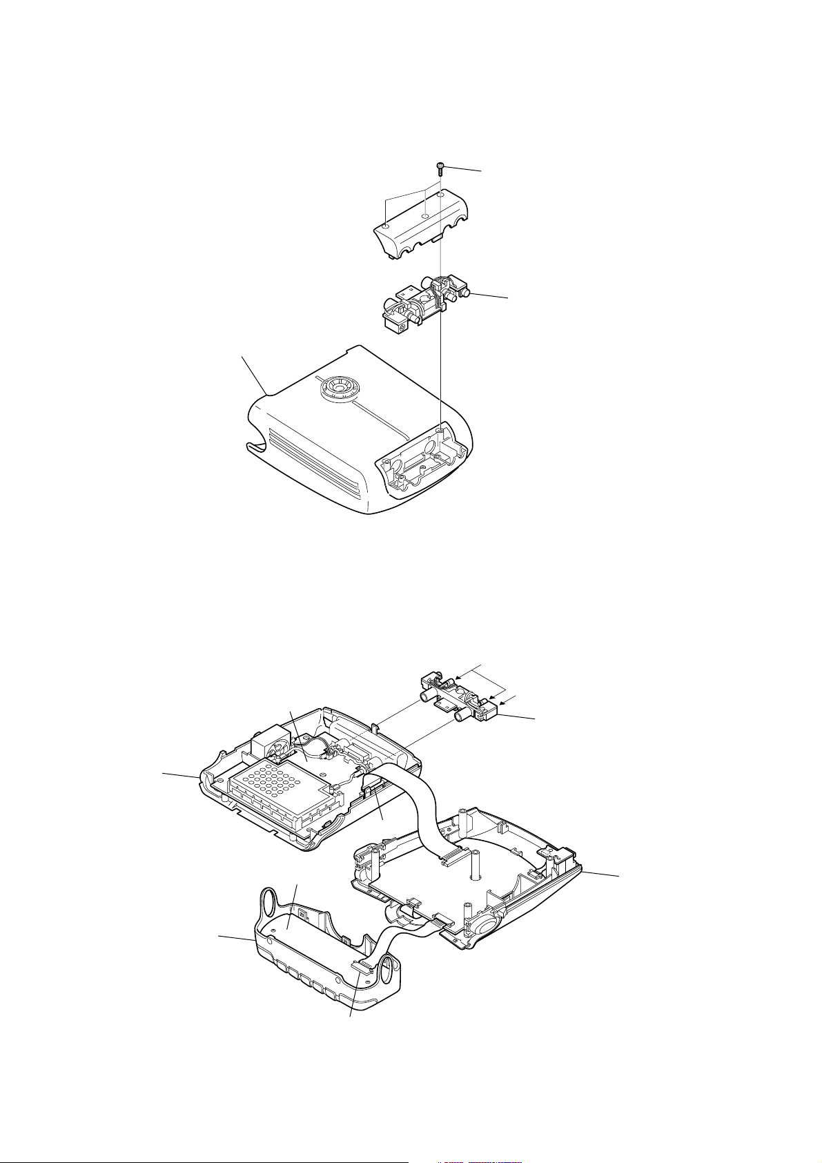
Disassemble the unit in the order as shown below.
SECTION 3
DISASSEMBLY
DRN-XM01C/XM01R/XM01H/
XM01CK/XM01HK
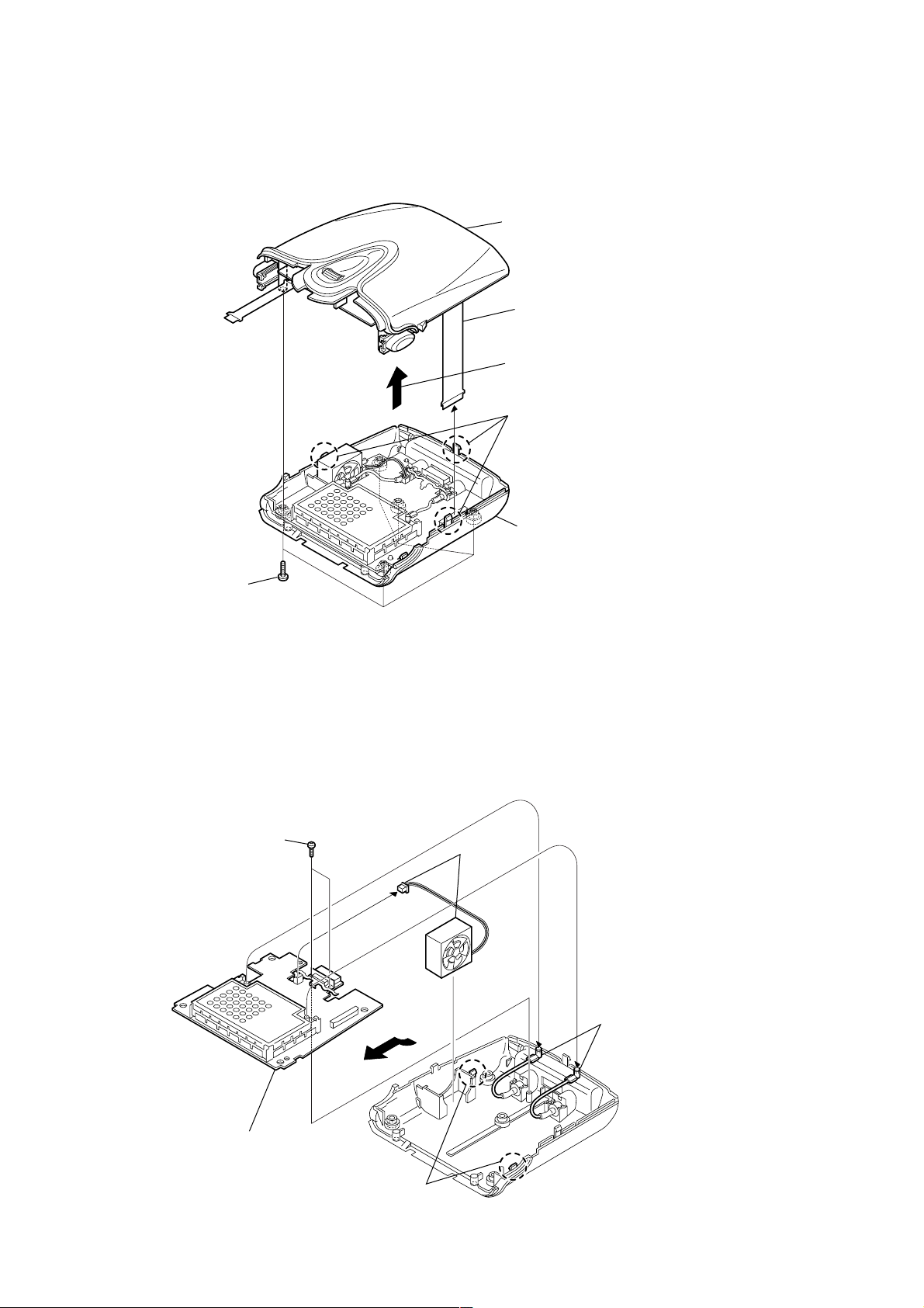
FRONT PANEL ASSY
LOWER CABINET ASSEMBLY,
UPPER CABINET ASSEMBLY
LCD BOARD
Note : Follow the disassembly procedure in the numerical order given.
3-1. FRONT PANEL ASSY
A
Button (release L)
4 Flexible board
(20P) (CN301)
2 Three claws
C
5 Front panel assy
BB BOARD, DC FAN
CPU BOARD, USB BOAR
Button (release R)
B
3 While pushing the button (release L)
and the button (release R) in the
direction of the arrow A and B,
remove the front panel assy in the
direction of the arrow C.
3-2. LCD BOARD
1 Two screws (M1.7)
1 Two screws
(M1.7 × 6)
3 LCD board
4 DSPL button
2 Two claws
7
Page 8
DRN-XM01C/XM01R/XM01H/
)
XM01CK/XM01HK
3-3. LOWER CABINET ASSMBLY,
UPPER CABINET ASSEMBLY
5 Upper cabinet assembly
3 Flexible board
(30P) (CN102 )
Remove the upper cabinet assembly
in the direction of the arrow.
2 Three claws
1 Five screws
(+BTP 2.6 × 10)
3-4. BB BOARD, DC FAN
3 Two screws
(M1.7 × 6)
4 Lower cabinet assembly
1 DC fan
(CN104)
2 Two cables
(with connector
5 Remove the BB board
in the direction of the arrow.
4 Two claws
8
Page 9
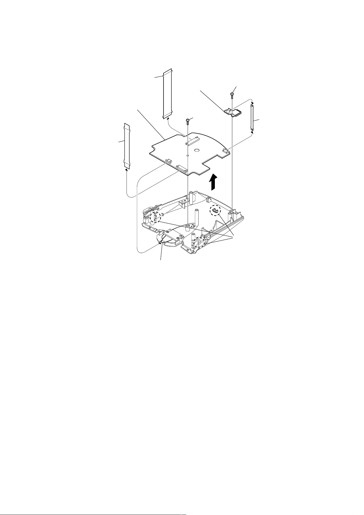
3-5. CPU BOARD, USB BOARD
1 Flexible board
(30P) (CN501)
9 Remove the CPU board in
the direction of the arrow.
6 USB board
7 Screw
(M1.7 × 6)
DRN-XM01C/XM01R/XM01H/
XM01CK/XM01HK
4 Screw
(M1.7 × 6)
(CN2)
5 Flexible board (USB)
2 Flexible board
(20P) (CN502 )
(CN504)
8 Three claws
3 Flexible board
(JOG) (CN503)
9
Page 10
DRN-XM01C/XM01R/XM01H/
XM01CK/XM01HK
Ver 1.1 2001.12
SECTION 4
TEST MODE
4-1. TEST MODE
4-1-1. SETTING THE TEST MODE
The following is the method of entering the test mode under the
condition of power-off.
Procedure:
1. Press the JOG roller and the preset button 2 simultaneously for
three seconds.
2. Press the preset button 1 .
3. Press the preset button 3 .
4. Press the preset button 5 .
5. The menu screen is displayed.
4-1-2. EXITING THE TEST MODE
Press the POWER button excluding LCD/KEY/BACKLIGHT Test
Mode.
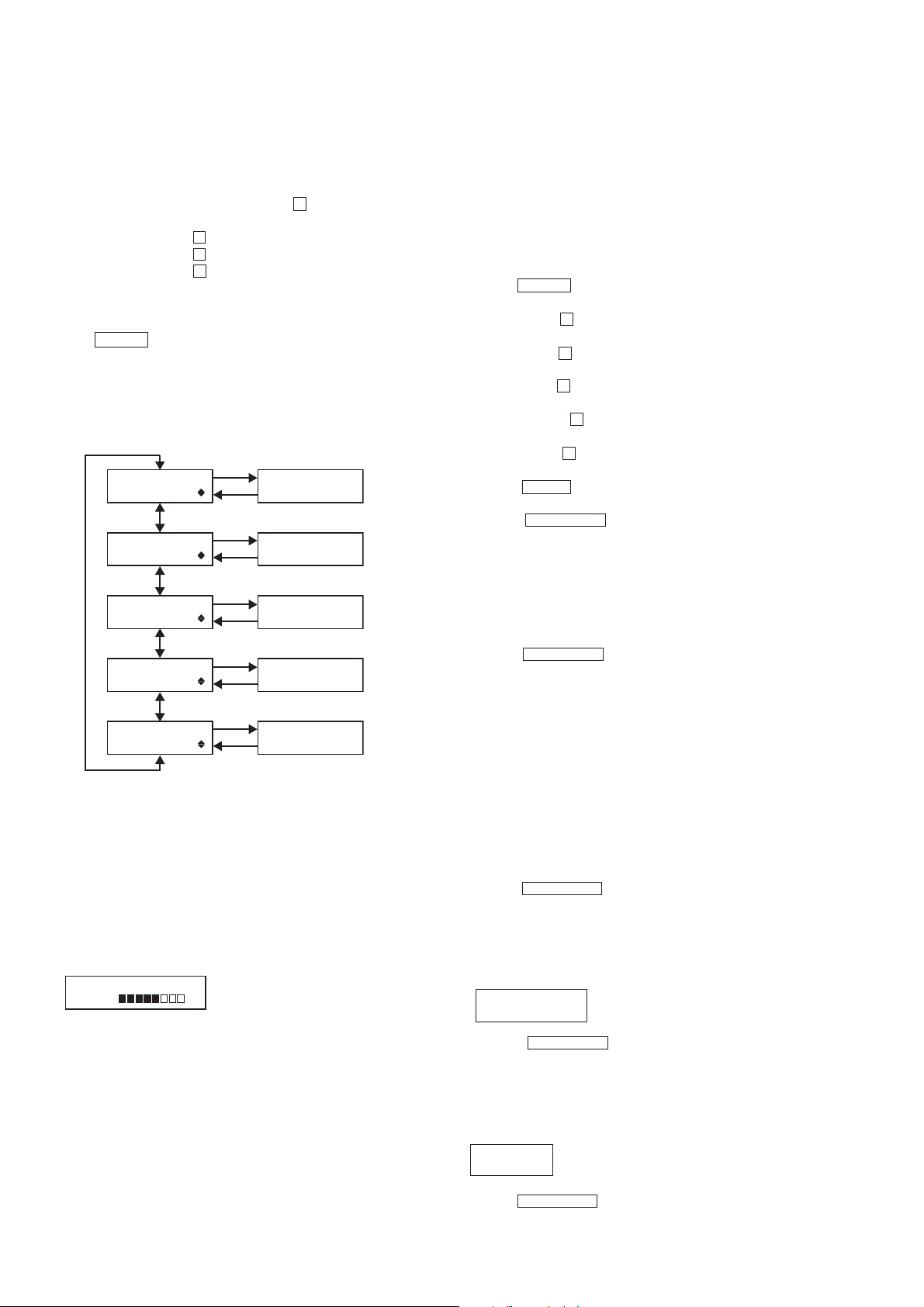
4-1-3. TEST MODE MENU
Select the menu and press the JOG roller.
(MENU) (MODE)
JOG roller
TEST MENU
LCD ADJUST
TEST MENU
LCD/KEY/BKLIGHT
TEST MENU
EEP INIT.
TEST MENU
SOFT VERSION
TEST MENU
SERIAL NO.
JOG PUSH
DSPL/BACK
LCD
Adjustment Mode
LCD/KEY/BACKLIGHT
Check Mode
EEPROM
Initialization Mode
SOFT VERSION
Display Mode
SERIAL NO.
Display Mode
4-1-4. OPERATION OF THE TEST MODE
[LCD Adjustment Mode]
* This mode is used to adjust the contrast of LCD to the medium
value.
This adjustment is different from user's adjustment of the contrast
in 8 levels.
Procedure:
1. Select the MENU LCD ADJUST and press the JOG roller.
2. The following screen is displayed.
LCD ADJUST XX
L H
XX : LCD Contrast Value (00 to 31)
4-1-5. OPERATION OF THE TEST MODE
[LCD/KEY/BACKLIGHT Check Mode]
* This mode is used to check the operation of LCD, Keys, the JOG
roller, the backlight and the power LED.
Procedure:
1. Select the MENU LCD/KEY/BKLIGHT and press the JOG roller.
The test is excuted by pressing buttons correctly in the following
order.
2. All segments of LCD and the power LED are turnd on and the
backlight is lit brightly.
3. Press the POWER button. segments of LCD changes to checkers
and the backlight keeps bright.
4. Press the preset 1 button. LCD displays reverse checkers and
the backlight is bright.
5. Press the preset 2 button. LCD displays lateral stripes and the
backlight is bright.
6. Press the preset 3 button. LCD displays vertical stripes and the
backlight is bright.
7. Press the preset 4 button. LCD displays chekers and the
backlight is dim.
8. Press the preset 5 button. LCD displays reverse chekers and
the backlight is dim.
9. Press the MEMO button. LCD displays lateral stripes and the
backlight is dim.
10. Press the DSPL/BACK button. LCD displays vertical stripes
and the backlight is dim.
11.
Rotate the JOG roller down. The message “JOG TEST COUNT : :
00” is displayed. Rotate the JOG roller down to “COUNT : : 08”.
12. Rotate the JOG roller up. The value “JOG TEST COUNT : : 08”
decreases to “COUNT : : 00”.
13. Press the JOG roller. LCD, the backlight and the power LED
are turned out.
14. Press the DSPL/BACK button to return to the TEST MENU.
[EEPROM Initialization Mode]
* This mode is used to initialize the values of EEPROM without
LCD factory adjustment value and the serial number.
Note: When this mode is activated, all of the information that has
been preset by customer is cleared. Before activating this mode,
take a note of the information that has been preset by customer.
After Test mode is completed, set the saved information to
recover the original setup.
Procedure:
1. Select the MENU EEP INIT. and press the JOG roller. Then
initialization is executed.
2. The message “EEP INT. COMPLETE” is displayed.
3. Press the DSPL/BACK button to return to the TEST MENU.
[SOFT VERSION Display Mode]
Procedure:
1. Select the MENU SOFT VERSION and press the JOG roller.
2. The following message is displayed,
SOFT VERSION R : ROM
R : 01.00 F : 01.00 F : Flash
3. Adjust the LCD to the center contrast in 32 levels by rotating
the JOG roller up or down.
4. Press the JOG roller to set the value.
5. The display returns to the TEST MENU.
10
3. Press the DSPL/BACK button to return to the TEST MENU.
[SERIAL NO. Display Mode]
Procedure:
1. Select the MENU SERIAL NO. and press the JOG roller.
2. The following message is displayed.
SERIAL NO.
XXXXXX XXXXXX : Serial No. (6 digits)
3. Press the DSPL/BACK button to return to the TEST MENU.
Page 11
DRN-XM01C/XM01R/XM01H/
XM01CK/XM01HK
Ver 1.1 2001.12
4-2. DIAGNOSTIC MODE
4-2-1. SETTING THE DIAGNOSTIC MODE
Press the JOG roller and the preset button 5 simultaneously for
three seconds under the condition of power-off.
Press the JOG roller when the set is powered on.
4-2-2. EXITING THE DIAGNOSTIC MODE
Press the POWER button to exit from this mode.
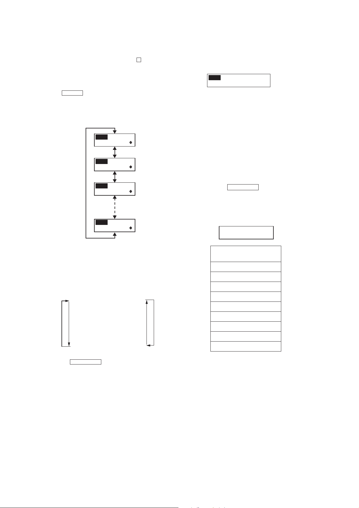
4-2-3. MENU
Select the menu and press the JOG roller.
JOG roller
MENU
DIAG. MODE
MENU
BER
MENU
SCROLL MODE
MENU
LINE OUT LEVEL
[BER Display Mode]
Procedure:
1. Select the MENU BER and press the JOG roller.
2. The following message is displayed.
MENU
XXX1 XXX2 XXX3
XXX4 XXX5 X6 X7
XXX1 : SAT1 BER
(4 digits Hex data)
XXX2 : SAT2 BER
(4 digits Hex data)
XXX3 : TERR BER
(4 digits Hex data)
XXX4 : RS Error Byte
(4 digits Hex data)
XXX5 : RS Error Block
(4 digits Hex data)
X6 : SAT AGC
(2 digits Hex data)
X7 : TER AGC
(2 digits Hex data)
3. Press the DSPL/BACK button to return the DIAG. MENU.
4-3. SYSTEM ERROR LIST
If system error is happened, the message of system error is displayed
and the set sounds beep.
SYSTEM ERROR xx
XXXXXXXXXXXXXXXXXXXX
xx : Error information per bit
4-2-4. OPERATION
[Diagnostic Mode]
Procedure:
1. Select the MENU DIAG. MODE and press the JOG roller.
2. The message “STATE1 QOS Test” is displayed.
3. Select the message(menu) by rotating the JOG roller up or down
as following order.
STATE1 QOS Test
STATE2 Terr Err
STATE3 Sat1 Err
STATE4 Sat2 Err
STATE5 Tuner Stat
STATE6 Audio Err
STATE7 Gen Err
STATE8 Ext Err0
STATE9 Ext Err1
4. Press the DSPL/BACK button to return the DIAG. MENU.
UpDown
INFORMATION OF ERROR
(XXXXXXXXXXXXXXXXXXXX)
TUNER UNLOCKED
DSP NO RESPOND
DSP INCORRECT RESP.
UNSUPPORTED DSPSW
CDEC NO RESPOND
I2C BUS ERROR
CAP ERROR
EEPROM ERROR
EEPROM FORMAT ERROR
11
Page 12
DRN-XM01C/XM01R/XM01H/
XM01CK/XM01HK
SECTION 5
SERVICE TOOL
5-1. Installing USB Driver
This section describes how to install USB driver for DRN-XM01.
Operating environment
Operating environments of a PC to which the driver software is installed are as follows.
* Applicable OSs are Windows98SE, Windows 2000 and Windows ME.
* USB can be connected.
Installation
For Windows 98SE
1. Insert the driver software program CD into the PC.
2. Connect the PC and DRN-XM01 with USB cable.
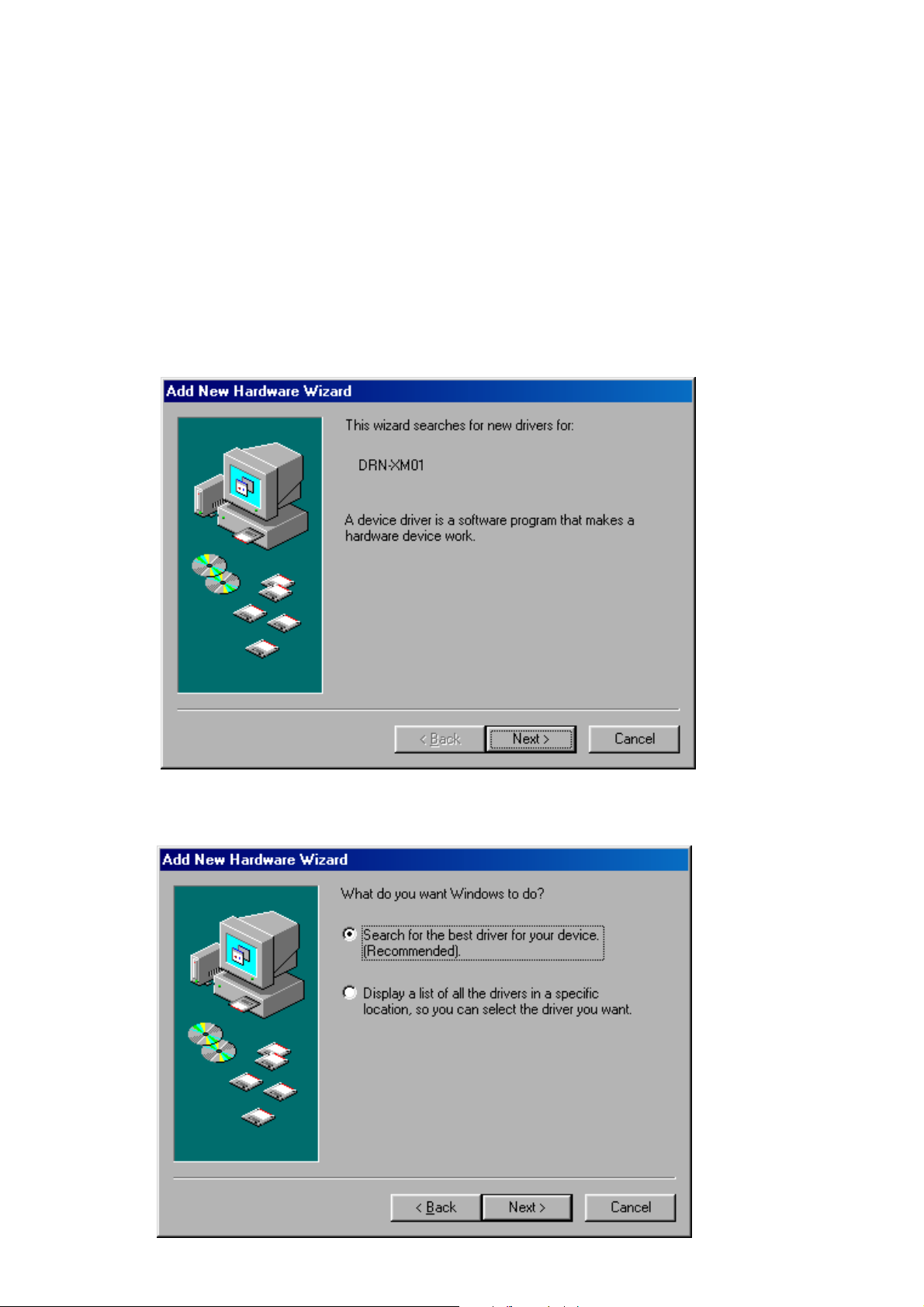
3. After a while, the following dialog box appears. Press the Next button.
4. Then the following dialog box appears. Select ”Search for the best driver for your device (Recommended).” and press the NEXT button.
12
Page 13

DRN-XM01C/XM01R/XM01H/
XM01CK/XM01HK
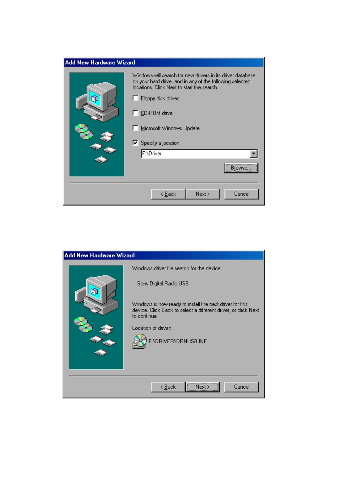
5. Then the following dialog box appears. Click on the check box ”Specify a location:” and press the Browse…button.
6. The following file selector dialog box appears. Select ”(CD drive):\Driver”(CD drive is F in this sample picture) and press the OK button.
13
Page 14
DRN-XM01C/XM01R/XM01H/
XM01CK/XM01HK
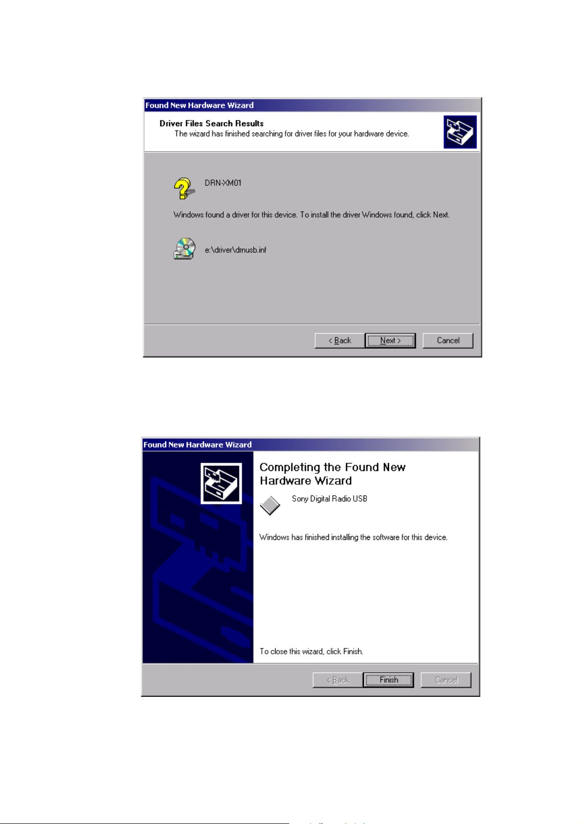
7. Confirm the path and press the NEXT button.
8. After a while, the following dialog box appears. Press the NEXT button.
14
Page 15
DRN-XM01C/XM01R/XM01H/
XM01CK/XM01HK
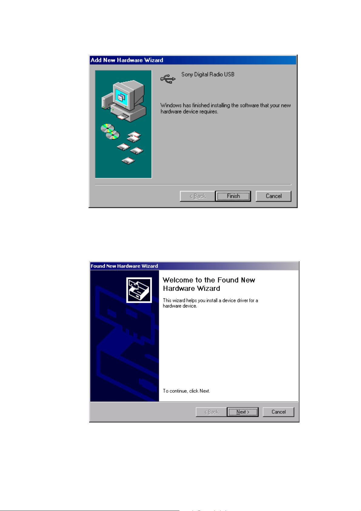
9. After a while, installation is completed and the following dialog box appears. Press the Finish button to terminate the installation program.
For Windows 2000
1. Insert the driver software program CD into the PC.
2. Connect the PC and DRN-XM01 with USB cable.
3. After a while, the following dialog box appears. Press the NEXT button.
15
Page 16
DRN-XM01C/XM01R/XM01H/
XM01CK/XM01HK
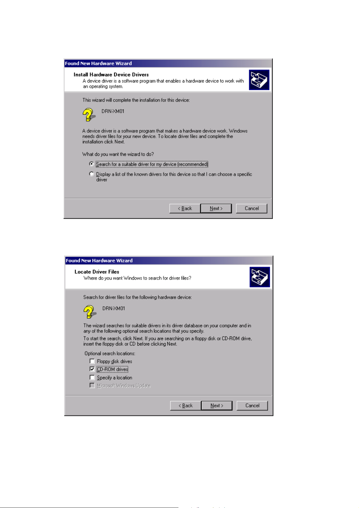
4. Then the following dialog box appears. Select ”Search for suitable driver for my device(recommended)” and press the NEXT button.
5. Then the following dialog box appears. Select ”CD-ROM drives” and press the NEXT button.
16
Page 17
6. After a while, the following dialog box appears. Press the Next button.
DRN-XM01C/XM01R/XM01H/
XM01CK/XM01HK
7. After a while, installation is completed and the following dialog box appears. Press the Finish button to terminate the installation program.
17
Page 18

DRN-XM01C/XM01R/XM01H/
XM01CK/XM01HK
For Windows ME
1. Insert the driver software program CD into the PC.
2. Connect the PC and DRN-XM01 with USB cable.
3. After a while, the following dialog box appears. Click the check box ”Automatic search for a better driver(Recommended)” and press the
NEXT button.
4. After a while, installation is completed and the following display appears. Press the Finish button to terminate the installation program.
18
Page 19

DRN-XM01C/XM01R/XM01H/
5-2. Installing DRN-XM01 Service Tool
This section describes how to use DRN-XM01 Service Tool.
Operating environment
Operating environments of a PC to which DRN-XM01 Service Tool is installed are as follows.
• Applicable OSs are Windows98SE, Windows 2000 and Windows ME.
• USB can be connected.
• USB driver for DRN-XM01 is installed.
Installation
1. Insert DRN-XM01 Service Tool CD into the PC.
2. Open ”DRN-XM01 Service Tool” in the CD drive with Explorer or the like and double-click Setup. exe.
XM01CK/XM01HK
Ver 1.1 2001.12
19
Page 20

DRN-XM01C/XM01R/XM01H/
XM01CK/XM01HK
Ver 1.1 2001.12
3. The following dialog box appears after a while. Press the Next button.
4. The following dialog box appears. Select an appropriate folder by pressing the [Browse…] button as desired. Press the Next button.
20
Page 21
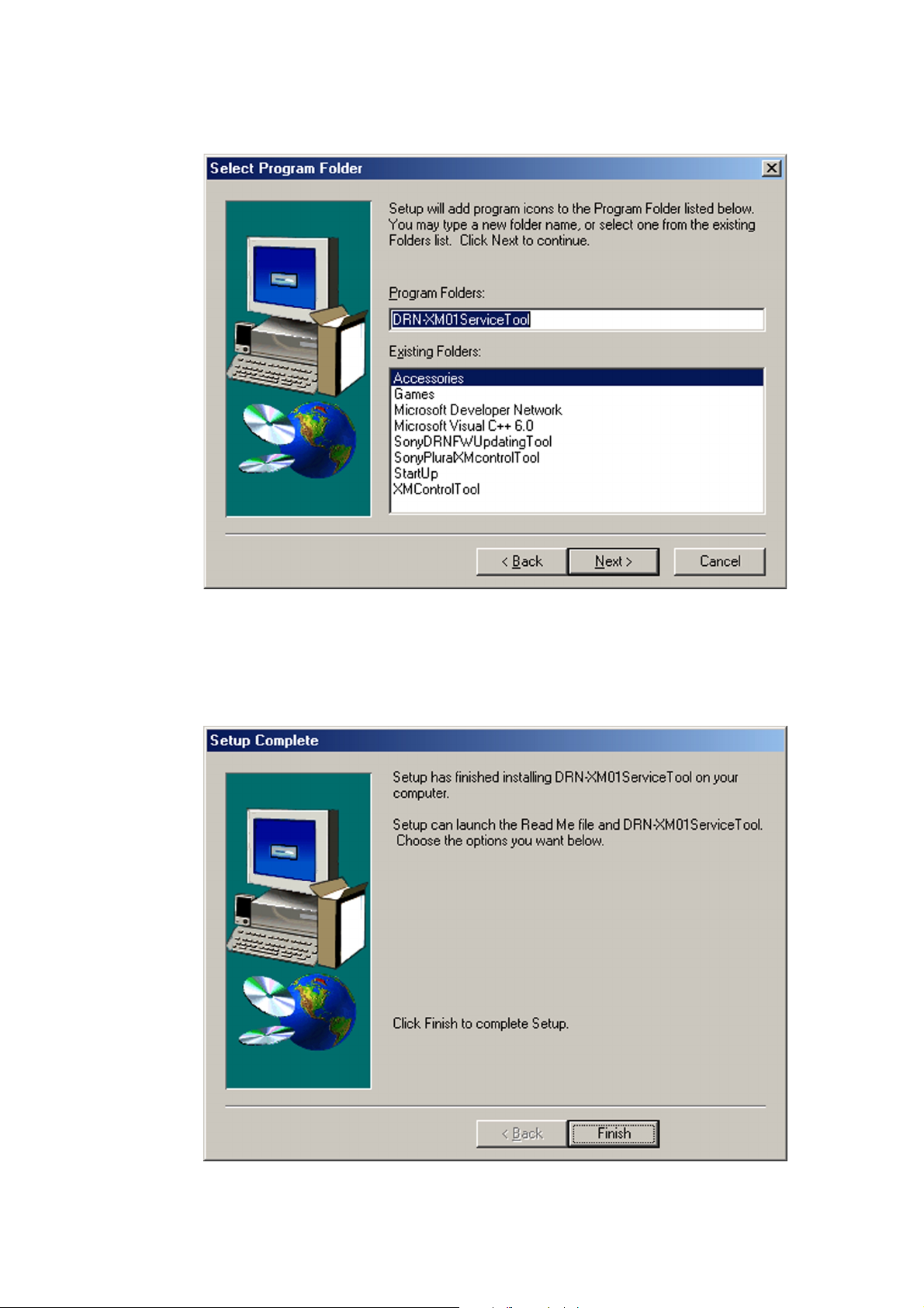
5. The following dialog box appears. Change if required and press the Next button.
DRN-XM01C/XM01R/XM01H/
XM01CK/XM01HK
Ver 1.1 2001.12
6. The following dialog box appears after a while. Press the Finish button to terminate the installation program.
21
Page 22

DRN-XM01C/XM01R/XM01H/
XM01CK/XM01HK
Ver 1.1 2001.12
5-3. How to use DRN-XM01 Service Tool
Note: When the Write Firmware program is executed, all of the information that has been preset by customer is cleared. Before executing
the Write Firmware program, take a note of the information that has been preset by customer. After execution of the Write Firmware
program is completed, set the saved information to recover the original setup.
1. Connect the DRN-XM01 power cord to the wall outlet and connect the DRN-XN01 to a PC with the USB cable.
Note: Even if the power of the DRN-XM01 is not turned on, the DRN-XM01 Service Tool firmware can be activated but an error occurs
during sequence of the execution. So, be sure to turn on the power of the DRN-XM01. Because DRN-XM01 Service Tool firmware
cannot be updated if the power of the DRN-XM01 is not turned on.
2. Select Start t Program t DRN-XM01ServiceTool to start up the tool.
3. When DRN-XM01ServiceTool starts up, the following dialog box appears prompting you to confirm that the characters "DRN-XM01" is
displayed in the Product Name (1), the present version in the Device Version (2) and the present serial number in the Serial No text boxes.
(When the serial number is not written due to replacement of CPU board or others, the characters "------" appear.)
22
Page 23

DRN-XM01C/XM01R/XM01H/
XM01CK/XM01HK
Ver 1.1 2001.12
4. When File t Open is selected on the menu bar, the file selection dialog box appears. Select the firmware update file (extension .rom) for
the DRN-XM01 and confirm the file version that appears in File Version (4) text box. When the characters "------" are displayed in the
Serial No text box, input the serial number that is printed on the label on the back of the machine, into the Serial No text box.
5. When Firmware t Write Firmware is selected, the following progress dialog box appears.
23
Page 24

DRN-XM01C/XM01R/XM01H/
XM01CK/XM01HK
Ver 1.1 2001.12
6. When writing of the firmware is completed, the pop-up menu appears as shown below. Confirm that the writing of the firmware has
completed with normal end.
7. When the OK button is pressed in step 6, Radio ID appears in the Radio ID (5) text box.
24
Page 25

DRN-XM01C/XM01R/XM01H/
XM01CK/XM01HK
Ver 1.1 2001.12
Log function
When View t Log File is selected, "Notepad" appears enabling you to view the firmware logs saved by this software up to present.
If this file is cleared by mistake or the contents are re-written or the tool is uninstalled, the logs will disappear.
25
Page 26

DRN-XM01C/XM01R/XM01H/
1
IC101 es (XTO)
1.3 Vp-p
42 ns
500mV/div 20ns/div
4
IC505 qd (XOUT)
3.8 Vp-p
83 ns
1V/div 40ns/div
2
IC501 wh (X2)
3.3 Vp-p
16 ns
1V/div 100ns/div
3
IC501 es (XT2)
2 Vp-p
31 ns
500mV/div 20µs/div
d
XM01CK/XM01HK
SECTION 6
DIAGRAMS
Note on Printed Wiring Boards
• X : parts extracted from the component side.
• : Pattern from the side which enables seeing.
(The other layers' patterns are not indicated.)
Caution:
Pattern face side: Parts on the pattern face side seen from the
(Side B) pattern face are indicated.
Parts face side: Parts on the parts face side seen from the
(Side A) parts face are indicated.
C
Q
These are omitte
EB
Note on Schematic Diagram
• All capacitors are in µF unless otherwise noted. pF: µµF
50 WV or less are not indicated except for electrolytics
and tantalums.
• All resistors are in Ω and
specified.
f
•
• C : panel designation.
.
Note: The components identified by mark 0 or dotted
: internal component
line with mark 0 are critical for safety.
Replace only with part number specified.
1
4
/
W or less unless otherwise
r
WAVEFORMS
• : B+ Line.
• Power voltage is dc 6.0V and fed with regulated dc power
supply from cradle.
• Voltages and waveforms are dc with respect to ground
under no-signal conditions.
• Voltages are taken with a VOM (Input impedance 10 MΩ).
Voltage variations may be noted due to normal production tolerances.
• Waveforms are taken with a oscilloscope.
Voltage variations may be noted due to normal production tolerances.
• Circled numbers refer to waveforms.
• Signal path.
F : SAT
f : TER
26
Page 27

6-1. BLOCK DIAGRAM – TUNER SECTION –
BB BOARD
DRN-XM01C/XM01R/XM01H/
XM01CK/XM01HK
FROM
CRADLE
(XM ANTENNA)
CPU
BOARD
CRADLE
CPU
BOARD
IC106
DAC
DIN
5
4
LRCIN
6
BCKIN
1
XTI
16
MD/DM0
17
MC/DM1
18
ML/MUTE
15
RSTB
IC50
SWITCHING REG
FB EXT
5 1
CE
IC51
SWITCHING REG
FB EXT
5 1
CE
IC52
+5V REG
VOUT VDD
1 3
CE
IC107(1/2)
7
VOUTL
12
VOUTR
9
Q51
POWER
SWITCH
4
POWER_DIG
Q52
POWER
SWITCH
4
TUNER_EN
4
LPF
LPF
6
IC107(2/2)
2
LF103
FILTER
MUTE
Q101-103
MUTE
CONTROL
LINE
1
Q105
Q104
MUTE
Q106,109
FAN
DRIVER
FU3
DEC_3.3V
AUDIO_L
AUDIO_R
Signal path
FAN1
DC 6V
POWER_DIG
TUNER_EN
DC 6V
DEC_3.3V
: SAT
: TER
FROM
CRADLE
TO
CRADLE
C
D
CPU
BOARD
CPU
BOARD
IF2TA_P
IF2TA_N
IF2SA_N
IF2SA_P
TAGC
SAGC
XTI/MCLK
MAO2
MAO1
MAI1
MRESET
INTR
SDA
SCL
IC101
CDEC
MADD0-11
83
PCSD1
85
PCDC1
82
PCFS1
108
MFP_CLK
MCLKO
35 5
IC104
SDRAM
MDQ0-7
MBS0
MBS1
MCKE
MCS0
MDQM
MWE
MCLKON
RAS
CAS
120
127
95-100
103-106
109,110
111
112
113
117
119
130
131
132
36
2,5,8,10
44,47
50,53
23-26
29-34
22,35
20
21
37
19
39
18
17
16
38
BA0
BA1
CKE
CS
DQM
RAS
CAS
WE
CLK
DQ0-7
A0-11
DEC_RESET
SDEC_INT
I2C_DATA
I2C_CLK
34
33
39
29
55
56
60
59
A/D_2.5V
TUNER_3.3V
TU101
TUNER UNIT
IC701
DIFFERENTIAL
DRIVER
8
1
4
2
5
14
D102
ANT_5V
I2C_CLK
10
11
12
13
6
8
TER_IN
SAT_IN
SPI_CLK
SPI_DATA
SPI_LE
CDEC_CLK_OUT
LOCK_DET
T_AUX
S_AUX
TER_IF2_OUT
SAT_IF2_OUT
TER_AGC_IN
SAT_AGC_IN
TER IN
SAT IN
TUNER_CLK
TUNER_DATA
TUNER_LE
A
TUNER_LOCK
ANT_DET
MOBILE_A
TO
MOBILE_B
MOBILE_OUT
DEC_RESET
CDEC_INT
SDEC_INT
I2C_DATA
I2C_CLK
Q108
AMP
DEC_RESET
CDEC_INT
SDEC_INT
I2C_DATA
5
1
4
SINGLE
TO
DIFFERENTIAL
DEC_RESET
CDEC_INT
I2C_DATA
I2C_CLK
14
15
20
21
29
30
33
88
87
92
28
53
70
69
B
DAC_DATA
DAC_CLK
DAC_LE
DAC_RESET
MUTE
DAC_DATA
DAC_CLK
DAC_LE
DAC_RESET
MUTE
IC102
SDEC
PCSD
PCDC
PCFS1(FIT_2)
PLL_SYNC(FIT_5)
CLK_IN
RESET_N
EVENT_IRQ
SDA
SCL
SDO
LRCKT
SCKT
OCLK
SDA_M
SCL_M
CAP_RST
IC54
+2.5V REG
VOUT VDD
1 3
IC53
+3.3V REG
VOUT EXT
3 4
73
72
74
75
14
13
8
CE
CE
IC103
CAP
PA0
17
PA1
5
RST
6
CLK
4
DEC_ 2.5V
4
5
Q53
DRIVER
DAC_DATA
DAC_CLK
DAC_LE
DAC_RESET
MUTE
FU4
Q55
ANT_5V
4V
2727
Page 28
DRN-XM01C/XM01R/XM01H/
XM01CK/XM01HK
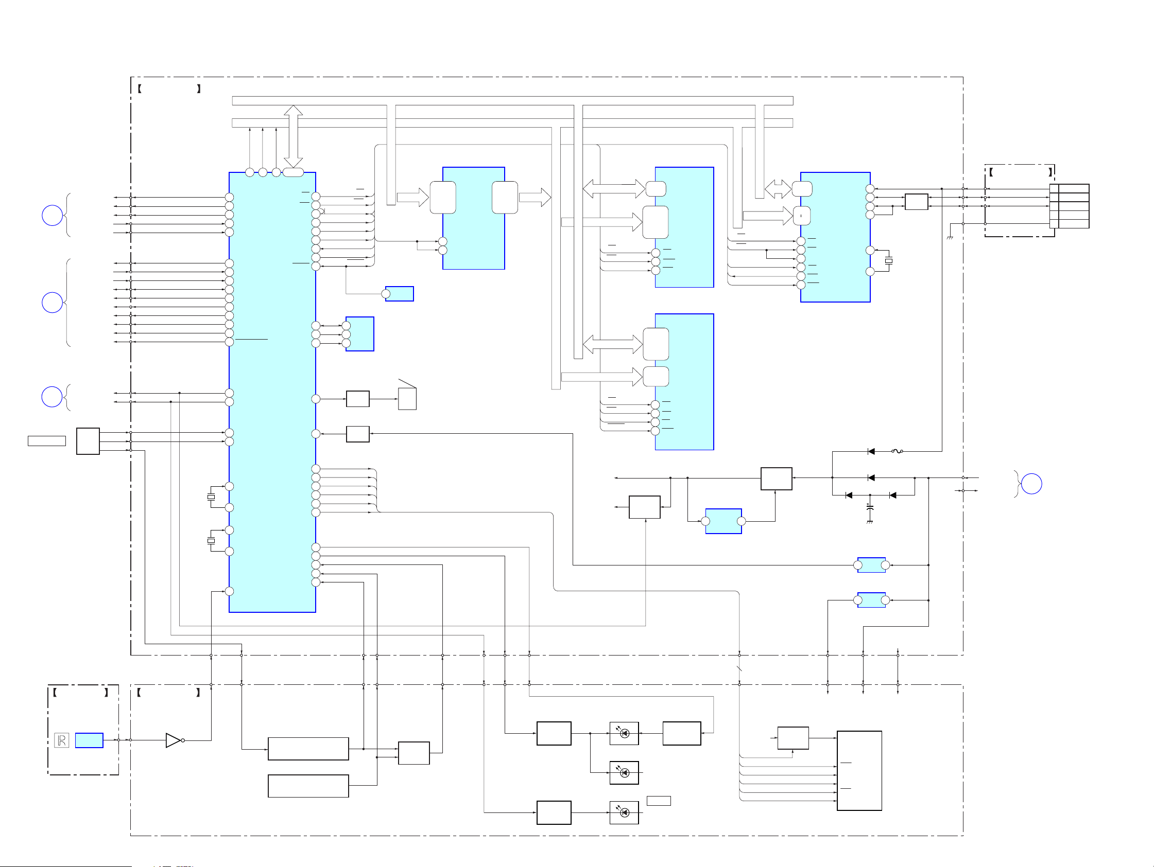
– CONTROL SECTION –
CPU BOARD
TUNER_CLK
BB
BOARD
BB
BOARD
BB
BOARD
MENU/ENTER
TUNER_DATA
A
B
C
TUNER_LE
TUNER_LOCK
ANT_DET
DEC_RESET
CDEC_INT
SDEC_INT
I2C_DATA
I2C_CLK
DAC_DATA
DAC_CLK
DAC_LE
DAC_RESET
MUTE
POWER_DIG
TUNER_EN
JOG
ROLLER
JOG A
JOG B
SW1
A18
A18 A17 A16
90
TUNER_CLK
70
TUNER_DATA
4
TUNER_LE
96
AN4(TUNER_LOCK)
94
AN2(ANT_DET)
DEC_RESET
8
CDEC_INT
14
SDEC_INT
10
84
SDA(CDEC,SDEC)
85
SCL(CDEC,SDEC)
42
DAC_DATA
40
DAC_CLK
39
DAC_LE
41
DAC_RESET
73
HWR(MUTE)
6
POWER_DIG
7
TUNER_POWER_EN
JOG_A INT2
36
99
AN7(JOG_B)
A17
6165 60
IC501
CPU
AD0-15
A16
44-59
AD0-15
WR
ALE
SRAMCS
FLASHCS
USBCS
USBINT4
USB_RESET
RESET
EEPROM-SDA
EEPROM-SCK
EEPROM-WP
BUZZER
VDET DC-IN
DATA BUS AD0 - 15
ADDRESS BUS A0 - 18
IC502
ADDR_LATCH
47,46,44
43,41,40
38-35
33,32,30
29,27,26
48
25
1LE
2LE
1D1-8,
2D1-8
RD
71
72
43
80
81
79
38
9
30
69
68
67
5
86
WR
ALE
SRAMCS
FLASHCS
USBCS
USB INT4
USB_RESET
RESET
IC509
EEPROM
SDA
5
SCL
6
7
WP
Q501
BUZZER
DRIVER
Q502
BUF
RD
AD0-15 A0-15
ALE
IC4
RESET
1
BZ501
1Q1-8,
2Q1-8
2,3,5
6,8,9
11-14
16,17,19
20,22,23
AD0-7 AD0-15
A0-16
RD
WR
SRAMCS
AD0-15
A1-18
RD
WR
FLASHCS
RESET
21-23
25-29
20-13
3,2
31,1,12
4,11
7,10
32
5
30
29,31,33
38,40,42
44,30,32
34,36,39
41,43,45
25-18
8-1
48,17
28
11
26
12
OE
R/W
CE1
OE
WE
CE
RST
IC503
SRAM
D1-8
A0-16
IC504
FLASH
D0-15
A0-17
A1-6
RD
WR
USBCS
USB INT4
USB_RESET
23-34
37-40
17
22
43
44
41
45
42
46
D0-15
A1-6
RD
WR
TEST2
CS
INT
RST
IC505
USB_MICOM
VBUS
TRON
XIN
XOUT
USB BOARD
X503
12MHz
FU1
LF501
LINE
FILTER
5
D-
3
D+
4
6
14
13
D2,9
CN1
1
VBUS
2
D-
3
D+
NC(ID)
4
5
DGND
IR BOARD
IC301
REMOTE
SENSOR
6.144MHz
LCD BOARD
Q301
X501
X502
32kHz
IR_INT
28
26
31
32
37
X1
X2
TX1
TX2
IR INT3
JOG_PUSH
LCD_RESET
LCD_CLK
LCD_SI
LCD_CS
LCD_A0
LCD_POWER
BACKLIGHT2
SCK(BACKLIGHT)
KEY INT1
AN0(KEY-A/D1)
AN1(KEY-A/D2)
S301-303
FUNCTION
SWITCH
S304-308
FUNCTION
SWITCH
19
20
18
16
17
13
74
83
35
92
93
LCD_RESET
LCD_CLK
LCD_SI
LCD_CS
LCD_A0
LCD_POWER
BACKLIGHT2
BACKLIGHT1
KEY INT
KEY-A/D1
KEY-A/D2
KEY-A/D2
KEY-A/D1
Q303,304
KEY
DET
KEY INT
TUNER_EN
BACKLIGHT1
BACKLIGHT2
Q302
LED
DRIVER
Q305
LED
DRIVER
CPU_3.3V
DEC_3.3V
POWER_DIG
(BACK LIGHT)
D304,305,S301-308
(KEY BACK LIGHT)
D301,302
Q2,3
B+
SWITCH
POWER
D303
Q307,308
BRIGHTNESS
CONTROL
IC3
SWITCHING REG
FB EXT
5 1
6
CPU_3.3V
LCD_POWER
LCD_RESET
LCD_CLK
LCD_SI
LCD_CS
LCD_A0
Q1
POWER
SWITCH
Q300,306
B+
SWITCH
D3
D4 D1
IC1
DC-IN
DET
VDD
RES
SCL
SI
CS1
A0
LED_6V
LCD301
IC11
+5V
REG
LED_6V
IR_5V
IR_5V
LIQUID CRYSTAL DISPLAY
C9
21
23
CPU_3.3V
CPU_3.3V
DC 6V
DEC_3.3VDEC_3.3V
BB
D
BOARD
2828
Page 29

6-2. PRINTED WIRING BOARDS – CPU BOARD –
DRN-XM01C/XM01R/XM01H/
XM01CK/XM01HK
A
B
C
D
12
CPU BOARD (SIDE A)
3456789101112
CPU BOARD (SIDE B)
USB BOARD
CN1
TP1
E
CN2
11
(11)
A
TO
BB BOARD
CN102
(Page 32)
IC1
1
5
4
3
IC3
5
4
IC4
1
3
1-682-676-
E
F
G
E
• Semiconductor Location
Ref. No. Location
D1 C-9
D2 C-9
D3 C-9
D4 C-9
D5 C-10
D6 D-9
D7 C-10
D9 C-9
D501 E-1
D504 F-9
D505 F-9
D506 F-9
D507 F-9
Ref. No. Location
IC1 C-8
IC3 C-10
IC4 D-10
IC11 F-10
IC501 E-10
IC502 E-8
IC503 E-8
IC504 E-7
IC505 D-8
IC509 E-3
Q1 C-10
Q2 D-10
Q3 D-10
Q501 E-1
Q502 F-10
1
4
IC509
IC505
IC504
5
4
13
IC501
E
1-682-676-
11
(11)
8
5
IC503
IC502
IC11
11
1-682-676-
(11)
TO
JOG ROLLER
MENU/ENTER
B
TO
LCD BOARD
CN301
(Page 36)
2929
Page 30
DRN-XM01C/XM01R/XM01H/
XM01CK/XM01HK
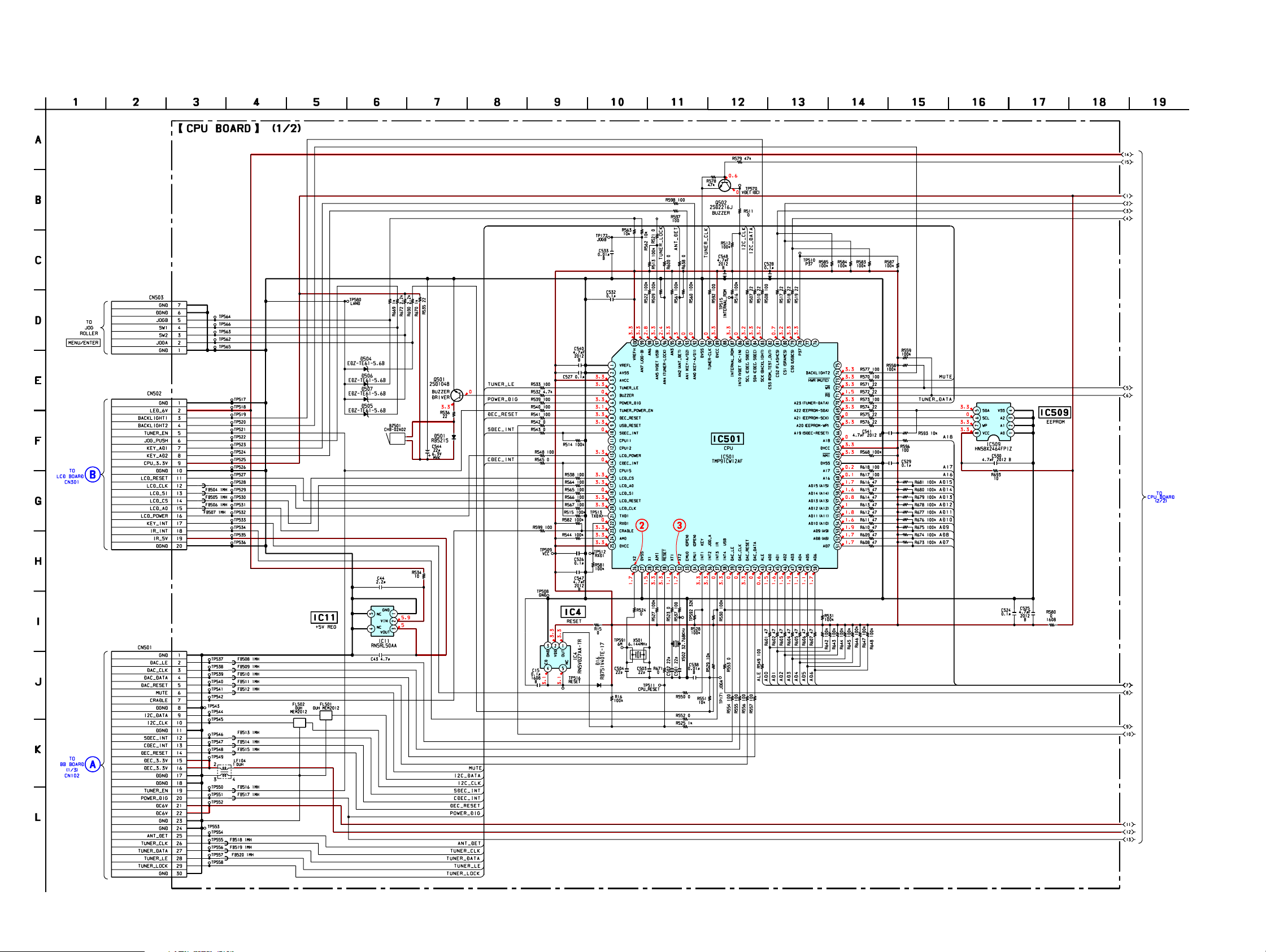
6-3. SCHEMATIC DIAGRAM – CPU BOARD (1/2) –
• See page 26 for Wavefoms. • See page 40 for IC Pin Function Description.
(Page 37)
(Page 33)
3030
Page 31

DRN-XM01C/XM01R/XM01H/
XM01CK/XM01HK
6-4. SCHEMATIC DIAGRAM – CPU BOARD (2/2) –
• See page 39 for IC Block Diagram. • See page 26 for Wavefom.
IC B/D
3131
Page 32

DRN-XM01C/XM01R/XM01H/
XM01CK/XM01HK
6-5. PRINTED WIRING BOARDS – BB BOARD –
A
B
C
12
34567891011
BB BOARD (SIDE A) BB BOARD (SIDE B)
TO
FAN1
IC106
IC51
IC107
IC53
IC50
E
E
E
IC102
TO
CRADLE
A
TO
CPU BOARD
CN501
(Page 29)
D
IC52
E
F
• Semiconductor Location
G
Ref. No. Location
D51 D-2
D52 B-2
D53 C-3
D54 E-2
D55 C-2
D56 C-2
D57 F-5
D101 C-7
D102 D-2
D106 B-3
D111 B-3
D112 B-4
D113 B-7
D114 B-7
D115 B-3
D116 B-3
IC104
Ref. No. Location
D117 B-3
D118 B-7
D119 B-3
D120 B-7
D121 C-3
D122 B-7
D123 B-7
D124 B-7
D125 D-1
D126 B-7
D151 E-3
D152 B-3
D153 B-3
D154 B-3
D155 B-3
IC101
IC701
Ref. No. Location Ref. No. Location
IC50 C-2
IC51 B-2
IC52 E-1
IC53 C-2
IC54 F-5
IC101 E-4
IC102 C-8
IC103 E-5
IC104 E-2
IC106 B-5
IC107 B-5
IC701 F-3
Q51 C-2
Q52 B-2
Q53 C-2
Q55 C-2
Q101 C-7
Q102 C-7
Q103 C-7
Q104 C-5
Q105 C-5
Q106 C-3
Q108 D-1
Q109 C-2
IC54
FOR
CAP-BINDING
IC103
TO
XM ANTENNA
(TER)
3232
1-682-677-
11
(11)
TO
XM ANTENNA
(SAT)
Page 33

6-6. SCHEMATIC DIAGRAM – BB BOARD (1/3) –
DRN-XM01C/XM01R/XM01H/
XM01CK/XM01HK
Ver 1.1 2001.12
330k
220k
(Page 30)
3333
Page 34

DRN-XM01C/XM01R/XM01H/
XM01CK/XM01HK
6-7. SCHEMATIC DIAGRAM – BB BOARD (2/3) –
• See page 38 for IC Block Diagram. • See page 26 for Wavefom.
IC B/D
3434
Page 35

DRN-XM01C/XM01R/XM01H/
XM01CK/XM01HK
6-8. SCHEMATIC DIAGRAM – BB BOARD (3/3) –
FOR
CAP-BINDING
• See page 38, 39 for IC Block Diagrams.
IC B/D
IC B/D
3535
Page 36

DRN-XM01C/XM01R/XM01H/
XM01CK/XM01HK
6-9. PRINTED WIRING BOARDS – PANEL SECTION –
A
B
C
12
LCD BOARD (SIDE A)
IR BOARD (SIDE A)
3456789
DSPL/
BACK
(LIQUID CRYSTAL DISPLAY)
1-682-675-
54321
MEMOPOWER
(11)
11
D
E
F
G
H
IC301
1-682-679-
g
(11)
11
LCD BOARD (SIDE B)
IR BOARD (SIDE B)
11
(11)
1-682-679-
B
TO
CPU BOARD
CN502
(Page 29)
1-682-675-
(11)
• Semiconductor
Location
Ref. No. Location
D301 B-2
D302 B-7
D303 C-2
11
D304 C-2
D305 C-7
D311 F-6
D312 F-3
D313 E-5
D314 E-5
IC301 D-2
Q300 F-6
Q301 F-7
Q302 E-5
Q303 E-4
Q304 E-4
Q305 F-5
Q306 F-5
Q307 F-6
Q308 E-5
3636
Page 37

6-10. SCHEMATIC DIAGRAM – PANEL SECTION –
DRN-XM01C/XM01R/XM01H/
XM01CK/XM01HK
(Page 30)
3737
Page 38

DRN-XM01C/XM01R/XM01H/
XM01CK/XM01HK
6-11. IC BLOCK DIAGRAMS
IC101 STA400 IC102 STA450
VSS
PCDC1
PCBS1
MAO1
MAO2
NC
VSS
VDD
MAI1
NC
NC
MADD0
MADD1
MADD2
MADD3
MADD4
MADD5
VSS
VDD3
MADD6
MADD7
MADD8
MADD9
VSS
MFP CLK
MADD10
MADD11
MBS0
MBS1
MCKE
113
112
111
110
106
107
108109
102
103104105
97
99100101
98
9596
9293
90
94
91
878889
84
86
85
VSS
VDD
VDD3
MCS0
MCS1
MDQM
MDQ0
MDQ1
MDQ2
MDQ3
MDQ4
MDQ5
MDQ6
MDQ7
VSS
VDD
RAS
CAS
MWE
FTESTOUT0
FTESTOUT1
FTESTOUT2
FTESTOUT3
FTESTOUT4
VSS
VDD3
FTESTOUT5
FTESTOUT6
FTESTOUT7
FTESTOUT8
FTESTOUT9
FTESTOUT10
FTESTOUT11
FTESTOUT12
FTESTOUT13
FTESTOUT14
FTESTOUT15
VDD
VDD3
VSS
TREFM
114
115
116
117
118
119
120
122
123
124
125
126
127
129
130
131
132
133
135
136
137
138
139
140
141
142
143
144
121
128
134
83
PCSD1
82
PCFS1
81
868583 82 79
DEPUNCYURING
WEIGHTING AND
8 bit
AGC
14 15
VITERBI
DECODER
RS
DECODER
SAT/SAT
COMBINING
TERR. FIFO
FIFO FIFO FIFO
SAL1 TDM
SYNCH. AND
DESCRAMBLING
SATELLITE 1
QPSK
DEMODULATOR
TDM
DEMUX
SAL1 AND SAL2
TERR/SAT.
COMBINING
WEIGHTING
FACTOR
CALCULATION
20
8 bit
AGC
FEC
SAL2 TDM
SYNCH. AND
DESCRAMBLING
SATELLITE 2
DEMODULATOR
19,22-25
21
PORT #1
BITSTREAM
INTERFACE #1
QPSK
PC
PC
CONTROLLER
TDM MANAGEMENT
INTERFACE #2
PRC
DEMUX
TDM DECODING
BER MEAS.
TERR. FIFO
EXTEMAL
MEMORY
CONTROLLER
FIFO
88
87
TERR. TDM
SYNCH. AND
DESCRAMBING
92
1
2
3
4
5
6
7
8
9
10
TERRESTRIAL
MULTI CARRIER
DEMODULATOR
TERR
AGC
78
77
76
PC
PORT #2
PC
BITSTREAM
TERR
AGC
74
75
TEST
INTERFACE
INTERFACE
MICROPROCESSOR
CLOCK
DISTRIBUTION
80
79
78
77
76
75
74
73
72
71
70
69
68
67
66
65
64
63
62
61
60
59
58
57
56
55
54
53
52
51
50
49
48
47
46
45
44
43
42
41
VSS
NC
PCTS EF1
PCBS2
PCDC2
PCSD2
PCFS2
PCTS EF2
BIST EM
SCAN WN
TEST EN
SDA
SCL
VSS
VDD
VDD3
IF2SD0
IF2SD1
IF2SD2
IF2SD3
IF2SD4
IF2SD5
IF2SD6
IF2SD7
LOCK M
CLKD
VDD
VSS
INTR
FTESTEN
IF2TD0
IF2TD1
IF2TD2
IF2TD3
IF2TD4
IF2TD5
IF2TD6
IF2TD7
IF2TD8
IF2TD9
VSS
RFU
GND1
VDD1
TEST0
CLK IN
RFU
TESTB
CAP RST
GND2
VDD2
VDD IO1
CLK OUT
SCL-M
SDA-M
GND3
VDD3
RFU
SCAN
MODE
APLL
GND
APLL
VDD
VDD12
I958 OUT
INPUT
BUFFER
GND4
77
AUDIO PLL
24
VDD4
GND12
76
I2C MASTER
(CAP I/F)
25
CLK M126CLK M0
RS232 TX
RS232 RX
78
79
80
1
2
3
4
5
6
7
8
9
10
11
12
13
14
15
16
17
18
19
20
33
34
13
14
PC BITSTREAM
INTERFACE
(USSIO O)
INPUT
SYSTEM AND AUDIO CLOCKS
SYS PLL
22
21
23
FLT 1
FILT 0
OCLK
75
CDO
SCKT
74
73
I2 SLAVE
(SYSCON I/F)
SERVICE
LAYER DEMUX
DSP BASED
27
RFU28RFU
72
59
29
PLL
LRCKT
60
SYNC
VDD IO4
71
30
GND5
VDD11
70
596164
GPIO
INTERFACE
DECRYPTION
31
VDD5
GND11
69
32
VDD IO2
DP CLK
67
68
80
65
DECODER
33
PCDC34PCSD
DP DATA
RS232
AYDIO
DP EN
66
79
35
RFU36RFU
RFU
65
RFU
64
63
EXETERNAL
INTTERRUPT
37
38
GND6
VDD10
39 29
OUTPUT
BUFFER
VDD6
62
39
GND10
PCFS
61
40
RFU
FIT 1
SPDIFF
OUTPUT
AUDIO PORT
OUTPUT
INTERFACE
(PCM I/F)
DATA PORT
OUTPUT
INTERFACE
(USSIO 3)
SDA
60
SCL
59
VDD9
58
GND9
57
EVENT
56
IRQ
RESET N
78
73
74
72
75
68
67
66
55
54
53
52
51
50
49
48
47
46
45
44
43
42
41
TEST1
DATA EN
VDD IO3
VDD8
GND8
DATA REQ
EXAUD
SCLK IN
EXAUD
DATA IN
RFU
VDD7
GND7
EXAUD
SCLK OUT
EXAUD
DATA OUT
RFU
11 12 13
TREFP
TADCREF
TINCM
14
15
IF2TA P
16
17 18 19 20 21 22 23 24 252627 28 29 30 31 32 33 34
TAGC
IF2TA N
TVCMO
AVDD
AGND
SVCMO
IF2SA N
IF2SA P
SINCM
SREFP
SADCREF
SREFM
AVDD
AGND
MRESET
SAGC
VSS
XTO
ADCSEL
XTI/MCLK
35
MCLKO
36
MCLKON
37 38
LOCK S1
39 40
LOCK S2
VDD3
VDD
3838
Page 39

IC106 PCM1717E-ST2
DRN-XM01C/XM01R/XM01H/
XM01CK/XM01HK
MODE
RSTB
MC/DM0
MD/DM1
ML/MUTE
CLKO
XTO
MULTI-LEVEL
SERIAL
14
15
16
17
18
19
20
INPUT
I/F
MODE
CONTROL
I/F
RESET
1 2 3
XTI
8X OVERSAMPLING
DIGITAL FILTER WITH
MULTI FUNCTION
CONTROL
CLOCK/OSC MANAGER
GND
VDD
DELTA-SIGMA
MODULATOR
MULTI-LEVEL
DELTA-SIGMA
MODULATOR
4
LRCIN
BPZ-CONT.
5 6
DIN
DAC
DAC
POWER SUPPLY
BCKIN
OUTPUT AMP
AND
LOW-PASS
FILTER
OUTPUT AMP
AND
LOW-PASS
FILTER
13
D/C L
VOUT L
12
11
VCC
AGND
10
9
VOUT R
8
D/C R
ZERO
7
IC505 M66291GP
VCC
GND
D-
D+
VBUS
TRON
TEST1
TRST/DREQ2
TCK/DACK2
TMS/HWR/SEL
TDI/A0
TDO/INT2/SOF
DACK
48
1
2
3
4
5
6
7
8
9
10
11
12
5
6
4
3
14
13
I/O BLOCK
OSCILLATION
BUFFER
/48MHzPLL
VBUS
INPUT CIRCUIT
D+ PIN PULLUP
CIRCUIT
USB
TRANSCEIVER
46
47
USB-IP
WR
CS
45
INTERRUPT CONTROLLER
TRANSFER
CONTROLLER
SERIAL
INTERFACE
ENGINE
(SIE)
RD
4344
TEST2
INT
42
ENDPOINT
CONTROLLER
FIFO MEMORY CONTROLLER
D15
40
41
FIFO MEMORY
D13
D14
39
D12
3738
BUS
INTERFACE
UNIT
(BIU)
8-10
36
GND
VCC
35
34
D11
D10
33
32
D9
31
D8
D7
30
29
D6
D5
28
D4
27
26
D3
11
D2
25
RST
DREQ
13 14 15 16 17 18 19
A1
XOUT
XIN
GND
VCC
A2
20
21 22 23 24
A3
A4
A5
A6
D0
D1
39
Page 40

DRN-XM01C/XM01R/XM01H/
XM01CK/XM01HK
6-12. IC PIN FUNCTION DESCRIPTION
• IC501 TMP91CW12AF-SR7501 (CPU)
Pin No.
1
2
3
4
5
6
7
8
9
10
11
12
13
14
15
16
17
18
19
20
21
22
23
24
25
26
27
28
29
30
31
32
33
34
35
36
37
38
39
40
41
42
43
44 to 59
60
61
62
63
64
65
Pin Name
VREFL
AVSS
AVCC
TUNER_LE
BUZZER
POWER_DIG
TUNER_POWER_EN
DEC_RESET
USB_RESET
SDEC_INT
CPU11
CPU12
LCD_POWER
CDEC_INT
CPU15
LCD_CS
LCD_A0
LCD_SI
LCD_RESET
LCD_CLK
TXD1
RXD1
CRADLE
AM0
DVCC
X2
DVSS
X1
AM1
RESET
XT1
XT2
EMU0
EMU1
KEY INT1
JOG_A INT2
IR INT3
USB INT4
DAC_LE
DAC_CLK
DAC_RESET
DAC_DATA
ALE
AD0 - 15
A16
A17
DVSS
NMI
DVCC
A18
I/O
–
Analog reference voltage (ground)
–
Analog ground
–
Analog power supply
O
Tuner LE signal output
O
Buzzer control signal output
O
Power control signal output(CDEC,SDEC,ANT)(H:active)
O
Tuner power enable signal output (H:active)
O
CDEC and SDEC reset signal output
O
USB micom reset signal output
I
SDEC interrupt signal input
O
Not used (open)
O
Not used (open)
O
LCD power control signal output (L:off,H:on)
I
CDEC interrupt signal input
O
Not used (open)
O
LCD chip select signal output
O
LCD A0 signal output
O
LCD data signal output
O
LCD reset signal output
O
LCD clock signal output
O
For writing internal flash memory (open)
I
For writing internal flash memory (pull-down)
I
Not used
–
Operation mode setting input (pull-up)
–
Power supply
–
Connection for a crystal resonator (Main system clock)
–
Ground
–
Connection for a crystal resonator (Main system clock)
–
Operation mode setting input (pull-up)
I
System reset input
–
Connection for a crystal resonator (sub clock)
–
Connection for a crystal resonator (sub clock)
–
Not used (open)
–
Not used (open)
I
Key interrupt signal input
I
JOG A interrupt signal input
I
IR interrupt signal input
I
USB interrupt signal input from the USB micom
O
Strobe clock signal output to the DAC
O
Mode control signal output for BCKIN
O
DAC reset signal output
O
Mode control signal output for data
O
Address latch enable signal output
I/O
Address/data bus
O
Address bus
O
Address bus
–
Ground
I
Non-maskable interrupt input (pull-up)
–
Power supply
O
Address bus
Description
40
Page 41

DRN-XM01C/XM01R/XM01H/
XM01CK/XM01HK
Pin No.
66
67
68
69
70
71
72
73
74
75 to 77
78
79
80
81
82
83
84
85
86
87
88
89
90
91
92
93
94
95
96
97
98
99
100
Pin Name
A19
EEPROM-WP
EEPROM-SCK
EEPROM-SDA
TUNER-DATA
RD
WR
HWR(MUTE)
BACKLIGHT2
P34 - 36
P37
CS0(USBCS)
CS1(SRAMCS)
CS2(FLASHCS)
CS3(ROM_TEST_OUT)
SCK(BACKLIGHT)
SDA(CDEC,SDEC)
SCL(CDEC,SDEC)
INT0(VDET DC-IN)
INTERNAL_ROM
P65
DVCC
TUNER-CLK
DVSS
AN0(KEY-A/D1)
AN1(KEY-A/D2)
AN2(ANT_DET)
AN3
AN4(TUNER-LOCK)
AN5(VDET USB)
AN6
AN7(JOG-B)
VREFH
I/O
O
Address bus (Not used)
O
EEPROM write protect signal output
O
EEPROM serial clock signal output
I/O
EEPROM serial data signal input or output
O
Tuner data signal output
O
Read memory signal output
O
Write memory signal output
O
Muting control signal output
O
Backlight control signal output (H:bright,L:dim)
O
Not used (open)
O
Flash BOOT terminal (pull-up)
O
USB chip select signal output
O
SRAM chip select signal output
O
Flash memory chip select signal output
O
Internal ROM test out (Firmware update)
O
Backlight control signal output (H:active)
I/O
IIC data signal input or output
O
IIC clock signal output
I
Voltage detect signal input
I
Terminal for forced internal ROM mode (L:active)
O
Not used (open)
–
Power supply
O
Tuner clock signal output
–
Ground
I
Key input signal from the function key
I
Key input signal from the function key
I
Antenna signal detect input
I
Not used (pull-up)
I
Tuner lock detect signal input
I
VBUS voltage detect signal input (not used)
I
Not used (pull-up)
I
JOG B signal input
–
Analog reference voltage (connected to Vcc)
Description
41
Page 42

DRN-XM01C/XM01R/XM01H/
XM01CK/XM01HK
SECTION 7
EXPLODED VIEWS
NOTE:
• -XX, -X mean standardized parts, so they may
have some differences from the original one.
• Items marked “*” are not stocked since they
are seldom required for routine service. Some
delay should be anticipated when ordering these
items.
7-1. FRONT PANEL ASSEMBLY, LOWER PANEL ASSEMBLY
• The mechanical parts with no reference number
in the exploded views are not supplied.
• Hardware (# mark) list and accessories and
packing materials are given in the last of this
parts list.
12
13
a
14
15
TU101
not
supplied
15
not
supplied
b
10
17
LCD301
d
9
11
16
c
20
21
19
9
18
8
7
6
5
FAN1
4
3
a
2
Ref. No. Part No. Description Remarks Ref. No. Part No. Description Remarks
1 3-233-501-01 CABINET (LOWER)
2 1-823-236-11 CABLE (WITH CONNECTOR)
3 3-234-360-01 RING, FIXED
* 4 3-592-351-01 PAPER, VIBRATION PROOF (B)
5 3-235-910-01 PLATE (A), SHIELD
6 A-3021-590-A BB BOARD, COMPLETE
7 3-233-504-01 SHEET, INSULATION
8 3-235-911-01 TERMINAL, CONTACT
9 3-318-203-11 SCREW (1.7X6), TAPPING
10 3-363-895-11 SCREW (M1.7)
b
1
#1
d
UPPER CABINET ASSEMBLY
13 3-234-123-01 SHEET, ADHESIVE
14 X-3380-987-1 PANEL ASSY, FRONT
15 3-233-559-01 SPRING, COMPRESSION
16 3-233-488-01 BUTTON (DSPL)
17 1-682-679-11 IR BOARD
* 18 A-3062-637-A LCD BOARD, COMPLETE
* 19 3-009-156-01 SHEET, ADHESIVE
20 3-234-124-01 SHEET, REFLECTION
21 3-233-496-01 PLATE, LIGHT GUIDE
#1 7-685-535-14 SCREW +BTP 2.6X10 TYPE2 N-S
c
11 1-682-681-11 PWB, FLEXIBLE (30P)
12 3-233-486-01 PLATE, TRANSPARENT
42
FAN1 1-763-733-11 FAN, DC
LCD301 1-804-505-11 DISPLAY PANEL, LIQUID CRYSTAL
TU101 1-693-561-11 TUNER (XM SATELLITE RADIO)
Page 43
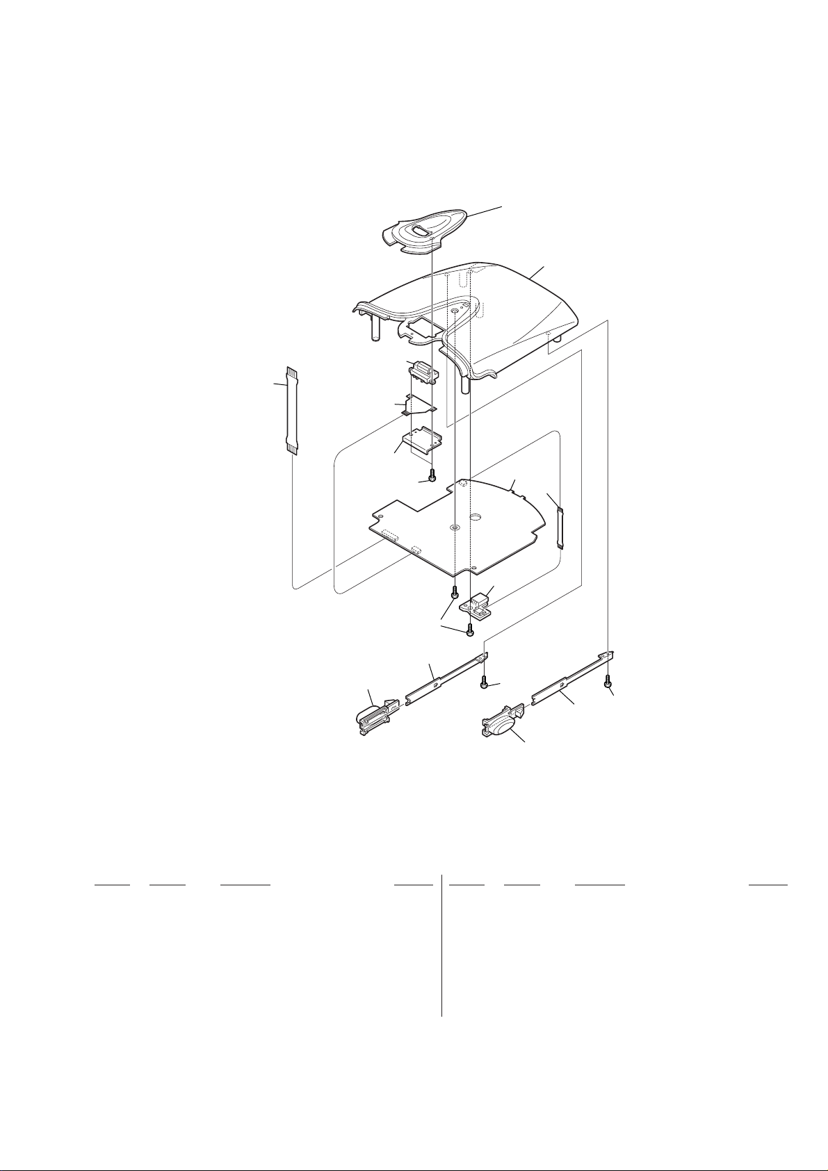
7-2. UPPER CABINET ASSEMBLY
63
DRN-XM01C/XM01R/XM01H/
XM01CK/XM01HK
65
64
62
61
52
60
55
56
54
57
55
59
51
58
53
55
Ref. No. Part No. Description Remarks Ref. No. Part No. Description Remarks
51 3-233-498-01 BUTTON (RELEASE R)
52 3-233-497-01 BUTTON (RELEASE L)
53 3-233-567-01 SPRING (RELEASE R), LEAF
54 3-233-566-01 SPRING (RELEASE L), LEAF
55 3-309-597-31 SCREW (1.4), TAPPING,PRECISION
56 3-318-203-11 SCREW (1.7X6), TAPPING
* 57 1-682-678-11 USB BOARD
58 1-682-683-11 PWB, FLEXIBLE (USB)
59 A-3021-589-A CPU BOARD, COMPLETE
60 3-233-560-01 BRACKET (JOG)
61 1-682-682-11 PWB, FLEXIBLE (JOG)
62 1-476-762-41 ENCODER (ROTARY)
63 1-682-680-11 PWB, FLEXIBLE (20P)
64 3-233-500-01 CABINET (UPPER)
65 3-233-499-01 PANEL (JOG)
43
Page 44

DRN-XM01C/XM01R/
XM01H/XM01CK/XM01HK
BB
NOTE:
• Due to standardization, replacements in the
parts list may be different from the parts
specified in the diagrams or the components
used on the set.
• -XX, -X mean standardized parts, so they
may have some difference from the original
one.
• Items marked “*” are not stocked since they
are seldom required for routine service.
Some delay should be anticipated when
ordering these items.
Ref. No. Part No. Description Remarks Ref. No. Part No. Description Remarks
A-3021-590-A BB BOARD, COMPLETE
*******************
3-233-565-01 WASHER, SLIT
3-235-910-01 PLATE (A), SHIELD
ELECTRICAL PARTS LIST
• CAPACITORS:
uF: µF
• RESISTORS
All resistors are in ohms.
METAL: metal-film resistor
METAL OXIDE: Metal Oxide-film resistor
F: nonflammable
• COILS
uH: µH
SECTION 8
• SEMICONDUCTORS
In each case, u: µ, for example:
uA...: µA... , uPA... , µPA... ,
uPB... , µPB... , uPC... , µPC... ,
uPD..., µPD...
When indicating parts by reference number,
please include the board name.
The components identified by mark 0 or
dotted line with mark 0 are critical for safety.
Replace only with part number specified.
C120 1-125-777-11 CERAMIC CHIP 0.1uF 10.00% 10V
C121 1-164-874-11 CERAMIC CHIP 100PF 5.00% 16V
C122 1-125-777-11 CERAMIC CHIP 0.1uF 10.00% 10V
C123 1-164-874-11 CERAMIC CHIP 100PF 5.00% 16V
C124 1-125-777-11 CERAMIC CHIP 0.1uF 10.00% 10V
< CAPACITOR >
C51 1-126-412-11 ELECT CHIP 220uF 20.00% 4V
C52 1-126-412-11 ELECT CHIP 220uF 20.00% 4V
C53 1-135-346-11 ELECT 39uF 20% 16V
C56 1-164-862-11 CERAMIC CHIP 33PF 5.00% 16V
C58 1-135-595-11 ELECT 100uF 20% 6.3V
C59 1-127-772-11 CERAMIC CHIP 33000PF 10% 10V
C61 1-135-346-11 ELECT 39uF 20% 16V
C63 1-164-862-11 CERAMIC CHIP 33PF 5.00% 16V
C65 1-135-595-11 ELECT 100uF 20% 6.3V
C66 1-127-772-11 CERAMIC CHIP 33000PF 10% 10V
C67 1-125-837-11 CERAMIC CHIP 1uF 10% 6.3V
C68 1-135-595-11 ELECT 100uF 20% 6.3V
C70 1-128-934-11 CERAMIC CHIP 0.33uF 20% 10V
C71 1-127-573-11 CERAMIC CHIP 1uF 10% 16V
C72 1-126-396-11 ELECT CHIP 47uF 20.00% 16V
C73 1-126-412-11 ELECT CHIP 220uF 20.00% 4V
C74 1-126-396-11 ELECT CHIP 47uF 20.00% 16V
C75 1-127-772-11 CERAMIC CHIP 33000PF 10% 10V
C76 1-125-838-11 CERAMIC CHIP 2.2uF 10% 6.3V
C77 1-125-838-11 CERAMIC CHIP 2.2uF 10% 6.3V
C78 1-126-412-11 ELECT CHIP 220uF 20.00% 4V
C79 1-127-772-11 CERAMIC CHIP 33000PF 10% 10V
C80 1-135-346-11 ELECT 39uF 20% 16V
C83 1-127-573-11 CERAMIC CHIP 1uF 10% 16V
C85 1-126-412-11 ELECT CHIP 220uF 20.00% 4V
C102 1-125-777-11 CERAMIC CHIP 0.1uF 10.00% 10V
C104 1-125-777-11 CERAMIC CHIP 0.1uF 10.00% 10V
C105 1-125-838-11 CERAMIC CHIP 2.2uF 10% 6.3V
C106 1-125-777-11 CERAMIC CHIP 0.1uF 10.00% 10V
C107 1-125-838-11 CERAMIC CHIP 2.2uF 10% 6.3V
C108 1-125-777-11 CERAMIC CHIP 0.1uF 10.00% 10V
C110 1-164-866-11 CERAMIC CHIP 47PF 5.00% 16V
C112 1-164-860-11 CERAMIC CHIP 27PF 5.00% 16V
C113 1-164-874-11 CERAMIC CHIP 100PF 5.00% 16V
C114 1-125-777-11 CERAMIC CHIP 0.1uF 10.00% 10V
C115 1-164-874-11 CERAMIC CHIP 100PF 5.00% 16V
C116 1-125-777-11 CERAMIC CHIP 0.1uF 10.00% 10V
C117 1-164-874-11 CERAMIC CHIP 100PF 5.00% 16V
C118 1-125-777-11 CERAMIC CHIP 0.1uF 10.00% 10V
C119 1-164-874-11 CERAMIC CHIP 100PF 5.00% 16V
C125 1-125-777-11 CERAMIC CHIP 0.1uF 10.00% 10V
C126 1-125-838-11 CERAMIC CHIP 2.2uF 10% 6.3V
C128 1-125-777-11 CERAMIC CHIP 0.1uF 10.00% 10V
C129 1-164-941-11 CERAMIC CHIP 0.0047uF 10.00% 16V
C130 1-164-935-11 CERAMIC CHIP 470PF 10.00% 16V
C131 1-164-935-11 CERAMIC CHIP 470PF 10.00% 16V
C132 1-164-941-11 CERAMIC CHIP 0.0047uF 10.00% 16V
C133 1-162-977-11 CERAMIC CHIP 0.0018uF 10.00% 50V
C134 1-162-977-11 CERAMIC CHIP 0.0018uF 10.00% 50V
C135 1-127-760-11 CERAMIC CHIP 4.7uF 10% 6.3V
C136 1-127-760-11 CERAMIC CHIP 4.7uF 10% 6.3V
C137 1-125-837-11 CERAMIC CHIP 1uF 10% 6.3V
C138 1-125-837-11 CERAMIC CHIP 1uF 10% 6.3V
C139 1-164-866-11 CERAMIC CHIP 47PF 5.00% 16V
C141 1-164-866-11 CERAMIC CHIP 47PF 5.00% 16V
C143 1-127-760-11 CERAMIC CHIP 4.7uF 10% 6.3V
C144 1-127-760-11 CERAMIC CHIP 4.7uF 10% 6.3V
C145 1-164-874-11 CERAMIC CHIP 100PF 5.00% 16V
C146 1-127-760-11 CERAMIC CHIP 4.7uF 10% 6.3V
C148 1-125-777-11 CERAMIC CHIP 0.1uF 10.00% 10V
C149 1-164-943-11 CERAMIC CHIP 0.01uF 10.00% 16V
C150 1-164-943-11 CERAMIC CHIP 0.01uF 10.00% 16V
C151 1-164-874-11 CERAMIC CHIP 100PF 5.00% 16V
C152 1-125-777-11 CERAMIC CHIP 0.1uF 10.00% 10V
C153 1-164-943-11 CERAMIC CHIP 0.01uF 10.00% 16V
C154 1-164-943-11 CERAMIC CHIP 0.01uF 10.00% 16V
C155 1-125-777-11 CERAMIC CHIP 0.1uF 10.00% 10V
C156 1-164-943-11 CERAMIC CHIP 0.01uF 10.00% 16V
C157 1-125-777-11 CERAMIC CHIP 0.1uF 10.00% 10V
C158 1-164-943-11 CERAMIC CHIP 0.01uF 10.00% 16V
C159 1-125-777-11 CERAMIC CHIP 0.1uF 10.00% 10V
C160 1-164-943-11 CERAMIC CHIP 0.01uF 10.00% 16V
C161 1-125-777-11 CERAMIC CHIP 0.1uF 10.00% 10V
C162 1-164-943-11 CERAMIC CHIP 0.01uF 10.00% 16V
C163 1-125-777-11 CERAMIC CHIP 0.1uF 10.00% 10V
C164 1-164-943-11 CERAMIC CHIP 0.01uF 10.00% 16V
C165 1-125-777-11 CERAMIC CHIP 0.1uF 10.00% 10V
C166 1-126-412-11 ELECT CHIP 220uF 20.00% 4V
C167 1-164-937-11 CERAMIC CHIP 0.001uF 10.00% 16V
C168 1-127-760-11 CERAMIC CHIP 4.7uF 10% 6.3V
44
Page 45

DRN-XM01C/XM01R/XM01H/
XM01CK/XM01HK
BB
Ref. No. Part No. Description Remarks Ref. No. Part No. Description Remarks
C169 1-164-937-11 CERAMIC CHIP 0.001uF 10.00% 16V
C170 1-127-760-11 CERAMIC CHIP 4.7uF 10% 6.3V
C171 1-125-777-11 CERAMIC CHIP 0.1uF 10.00% 10V
C172 1-164-943-11 CERAMIC CHIP 0.01uF 10.00% 16V
C173 1-164-943-11 CERAMIC CHIP 0.01uF 10.00% 16V
C229 1-127-760-11 CERAMIC CHIP 4.7uF 10% 6.3V
C230 1-127-760-11 CERAMIC CHIP 4.7uF 10% 6.3V
C231 1-127-760-11 CERAMIC CHIP 4.7uF 10% 6.3V
C232 1-127-760-11 CERAMIC CHIP 4.7uF 10% 6.3V
C233 1-127-760-11 CERAMIC CHIP 4.7uF 10% 6.3V
C174 1-164-943-11 CERAMIC CHIP 0.01uF 10.00% 16V
C175 1-164-943-11 CERAMIC CHIP 0.01uF 10.00% 16V
C176 1-164-943-11 CERAMIC CHIP 0.01uF 10.00% 16V
C177 1-164-943-11 CERAMIC CHIP 0.01uF 10.00% 16V
C178 1-164-943-11 CERAMIC CHIP 0.01uF 10.00% 16V
C179 1-127-760-11 CERAMIC CHIP 4.7uF 10% 6.3V
C180 1-127-760-11 CERAMIC CHIP 4.7uF 10% 6.3V
C181 1-164-937-11 CERAMIC CHIP 0.001uF 10.00% 16V
C182 1-164-937-11 CERAMIC CHIP 0.001uF 10.00% 16V
C183 1-164-937-11 CERAMIC CHIP 0.001uF 10.00% 16V
C184 1-164-937-11 CERAMIC CHIP 0.001uF 10.00% 16V
C185 1-164-937-11 CERAMIC CHIP 0.001uF 10.00% 16V
C186 1-164-937-11 CERAMIC CHIP 0.001uF 10.00% 16V
C187 1-164-937-11 CERAMIC CHIP 0.001uF 10.00% 16V
C188 1-164-937-11 CERAMIC CHIP 0.001uF 10.00% 16V
C189 1-164-937-11 CERAMIC CHIP 0.001uF 10.00% 16V
C190 1-164-943-11 CERAMIC CHIP 0.01uF 10.00% 16V
C191 1-164-943-11 CERAMIC CHIP 0.01uF 10.00% 16V
C192 1-125-777-11 CERAMIC CHIP 0.1uF 10.00% 10V
C193 1-164-943-11 CERAMIC CHIP 0.01uF 10.00% 16V
C194 1-164-943-11 CERAMIC CHIP 0.01uF 10.00% 16V
C195 1-164-943-11 CERAMIC CHIP 0.01uF 10.00% 16V
C196 1-125-777-11 CERAMIC CHIP 0.1uF 10.00% 10V
C197 1-164-943-11 CERAMIC CHIP 0.01uF 10.00% 16V
C198 1-164-943-11 CERAMIC CHIP 0.01uF 10.00% 16V
C234 1-127-760-11 CERAMIC CHIP 4.7uF 10% 6.3V
C235 1-127-760-11 CERAMIC CHIP 4.7uF 10% 6.3V
C236 1-127-760-11 CERAMIC CHIP 4.7uF 10% 6.3V
C237 1-127-760-11 CERAMIC CHIP 4.7uF 10% 6.3V
C238 1-127-760-11 CERAMIC CHIP 4.7uF 10% 6.3V
C239 1-127-760-11 CERAMIC CHIP 4.7uF 10% 6.3V
C240 1-127-760-11 CERAMIC CHIP 4.7uF 10% 6.3V
C241 1-127-760-11 CERAMIC CHIP 4.7uF 10% 6.3V
C242 1-127-760-11 CERAMIC CHIP 4.7uF 10% 6.3V
C265 1-125-837-11 CERAMIC CHIP 1uF 10% 6.3V
C266 1-127-760-11 CERAMIC CHIP 4.7uF 10% 6.3V
C267 1-127-760-11 CERAMIC CHIP 4.7uF 10% 6.3V
C268 1-127-760-11 CERAMIC CHIP 4.7uF 10% 6.3V
C272 1-137-934-11 TANTAL. CHIP 47uF 20% 10V
C273 1-137-934-11 TANTAL. CHIP 47uF 20% 10V
C274 1-127-760-11 CERAMIC CHIP 4.7uF 10% 6.3V
C275 1-127-760-11 CERAMIC CHIP 4.7uF 10% 6.3V
C276 1-127-760-11 CERAMIC CHIP 4.7uF 10% 6.3V
C277 1-127-760-11 CERAMIC CHIP 4.7uF 10% 6.3V
C278 1-127-760-11 CERAMIC CHIP 4.7uF 10% 6.3V
C279 1-164-937-11 CERAMIC CHIP 0.001uF 10.00% 16V
C280 1-164-937-11 CERAMIC CHIP 0.001uF 10.00% 16V
C281 1-164-937-11 CERAMIC CHIP 0.001uF 10.00% 16V
C282 1-164-937-11 CERAMIC CHIP 0.001uF 10.00% 16V
C283 1-164-937-11 CERAMIC CHIP 0.001uF 10.00% 16V
C199 1-164-943-11 CERAMIC CHIP 0.01uF 10.00% 16V
C200 1-125-777-11 CERAMIC CHIP 0.1uF 10.00% 10V
C201 1-164-943-11 CERAMIC CHIP 0.01uF 10.00% 16V
C202 1-164-943-11 CERAMIC CHIP 0.01uF 10.00% 16V
C203 1-164-943-11 CERAMIC CHIP 0.01uF 10.00% 16V
C204 1-164-943-11 CERAMIC CHIP 0.01uF 10.00% 16V
C205 1-164-943-11 CERAMIC CHIP 0.01uF 10.00% 16V
C206 1-164-874-11 CERAMIC CHIP 100PF 5.00% 16V
C207 1-125-777-11 CERAMIC CHIP 0.1uF 10.00% 10V
C208 1-125-838-11 CERAMIC CHIP 2.2uF 10% 6.3V
C209 1-164-937-11 CERAMIC CHIP 0.001uF 10.00% 16V
C210 1-127-760-11 CERAMIC CHIP 4.7uF 10% 6.3V
C211 1-164-937-11 CERAMIC CHIP 0.001uF 10.00% 16V
C212 1-164-937-11 CERAMIC CHIP 0.001uF 10.00% 16V
C213 1-127-760-11 CERAMIC CHIP 4.7uF 10% 6.3V
C214 1-127-760-11 CERAMIC CHIP 4.7uF 10% 6.3V
C215 1-164-866-11 CERAMIC CHIP 47PF 5.00% 16V
C216 1-164-866-11 CERAMIC CHIP 47PF 5.00% 16V
C217 1-127-760-11 CERAMIC CHIP 4.7uF 10% 6.3V
C218 1-164-937-11 CERAMIC CHIP 0.001uF 10.00% 16V
C219 1-164-937-11 CERAMIC CHIP 0.001uF 10.00% 16V
C220 1-164-937-11 CERAMIC CHIP 0.001uF 10.00% 16V
C221 1-107-826-11 CERAMIC CHIP 0.1uF 10.00% 16V
C222 1-107-826-11 CERAMIC CHIP 0.1uF 10.00% 16V
C223 1-127-760-11 CERAMIC CHIP 4.7uF 10% 6.3V
C224 1-127-760-11 CERAMIC CHIP 4.7uF 10% 6.3V
C225 1-125-777-11 CERAMIC CHIP 0.1uF 10.00% 10V
C226 1-127-760-11 CERAMIC CHIP 4.7uF 10% 6.3V
C227 1-127-760-11 CERAMIC CHIP 4.7uF 10% 6.3V
C228 1-127-760-11 CERAMIC CHIP 4.7uF 10% 6.3V
C701 1-125-777-11 CERAMIC CHIP 0.1uF 10.00% 10V
C702 1-164-858-11 CERAMIC CHIP 22PF 5.00% 16V
C703 1-164-858-11 CERAMIC CHIP 22PF 5.00% 16V
C704 1-125-777-11 CERAMIC CHIP 0.1uF 10.00% 10V
C705 1-125-777-11 CERAMIC CHIP 0.1uF 10.00% 10V
C706 1-125-777-11 CERAMIC CHIP 0.1uF 10.00% 10V
C707 1-127-760-11 CERAMIC CHIP 4.7uF 10% 6.3V
< CONNECTOR >
CN101 1-815-863-11 CONNECTOR (FEMALE)
CN102 1-778-544-11 CONNECTOR, FFC/FPC (ZIF) 30P
* CN104 1-565-135-11 PIN, CONNECTOR (STRAIGHT) 2P
< DIODE >
D51 8-719-066-33 DIODE RB081L-20TE25
D52 8-719-066-16 DIODE RB491D-T146
D53 8-719-071-34 DIODE RB521S-30-TE61
D54 8-719-071-34 DIODE RB521S-30-TE61
D55 8-719-071-34 DIODE RB521S-30-TE61
D56 8-719-071-34 DIODE RB521S-30-TE61
D57 8-719-071-34 DIODE RB521S-30-TE61
D101 8-719-421-27 DIODE MA728-TX
D102 8-719-066-16 DIODE RB491D-T146
D106 8-719-056-61 DIODE MAZS082008SO
D111 8-719-056-61 DIODE MAZS082008SO
D112 8-719-056-61 DIODE MAZS082008SO
D113 8-719-421-27 DIODE MA728-TX
D114 8-719-074-67 DIODE EDZ-TE61-5.6B
D115 8-719-074-67 DIODE EDZ-TE61-5.6B
45
Page 46

DRN-XM01C/XM01R/XM01H/
XM01CK/XM01HK
Ver 1.2 2002.11
BB
Ref. No. Part No. Description Remarks Ref. No. Part No. Description Remarks
D116 8-719-074-67 DIODE EDZ-TE61-5.6B
D117 8-71 9-074-67 DIODE EDZ-TE61-5.6B
D118 8-719-074-67 DIODE EDZ-TE61-5.6B
D119 8-719-074-67 DIODE EDZ-TE61-5.6B
D120 8-719-074-67 DIODE EDZ-TE61-5.6B
LF103 1-411-957-11 FILTER, COMMON MODE
< LINE FILTER >
< TRANSISTOR >
D121 8-719-074-67 DIODE EDZ-TE61-5.6B
D122 8-719-074-67 DIODE EDZ-TE61-5.6B
D123 8-719-074-67 DIODE EDZ-TE61-5.6B
D124 8-719-074-67 DIODE EDZ-TE61-5.6B
D125 8-719-056-61 DIODE MAZS082008SO
D126 8-719-421-27 DIODE MA728-TX
D151 8-719-074-67 DIODE EDZ-TE61-5.6B
D152 8-719-074-67 DIODE EDZ-TE61-5.6B
D153 8-719-074-67 DIODE EDZ-TE61-5.6B
D154 8-719-074-67 DIODE EDZ-TE61-5.6B
D155 8-719-074-67 DIODE EDZ-TE61-5.6B
< FERRITE BEAD >
FB101 1-469-084-21 FERRITE 1MH
FB102 1-469-084-21 FERRITE 1MH
FB108 1-469-084-21 FERRITE 1MH
FB109 1-469-084-21 FERRITE 1MH
FB110 1-469-084-21 FERRITE 1MH
< IC RINK >
FU3 1-533-397-11 RINK, CHIP IC
FU4 1-533-808-11 RINK, CHIP IC
< IC >
Q51 8-729-051-47 TRANSISTOR XP162A12A6PR
Q52 8-729-051-47 TRANSISTOR XP162A12A6PR
Q53 8-729-807-34 TRANSISTOR 2SB766A-R-TX
Q55 8-729-037-52 TRANSISTOR 2SD2216J-QR(TX).SO
Q101 8-729-230-60 TRANSISTOR 2SA1586YG-TE85L
Q102 8-729-037-74 TRANSISTOR UN9213J-(TX).SO
Q103 8-729-037-61 TRANSISTOR UN9113J-(TX).SO
Q104 8-729-013-37 TRANSISTOR 2SC4213-AB-TE85L
Q105 8-729-013-37 TRANSISTOR 2SC4213-AB-TE85L
Q106 8-729-807-34 TRANSISTOR 2SB766A-R-TX
Q108 8-729-037-52 TRANSISTOR 2SD2216J-QR(TX).SO
Q109 8-729-037-52 TRANSISTOR 2SD2216J-QR(TX).SO
< RESISTOR >
R52 1-208-947-11 METAL CHIP 330K 0.5% 1/16W
R53 1-208-943-11 METAL CHIP 220K 0.5% 1/16W
R54 1-218-985-11 RES-CHIP 470K 5% 1/16W
R55 1-218-989-11 RES-CHIP 1M 5% 1/16W
R56 1-208-670-11 METAL CHIP 300K 0.5% 1/16W
R57 1-208-935-11 METAL CHIP 100K 0.5% 1/16W
R58 1-218-983-11 RES-CHIP 330K 5% 1/16W
R59 1-218-989-11 RES-CHIP 1M 5% 1/16W
R60 1-218-965-11 RES-CHIP 10K 5% 1/16W
R61 1-218-990-11 SHORT 0
IC50 8-759-578-53 IC XC6365D103MR
IC51 8-759-578-53 IC XC6365D103MR
IC52 8-759-598-20 IC R1121N501B-TR
IC53 8-759-574-57 IC RN5RF33AA-TR
IC54 8-759-598-17 IC R1121N251B-TR
IC101 6-700-974-01 IC STA400
✩ IC102 ---------------- IC STA450
✩ IC103 ---------------- IC ST19AF08BR20QMAA
IC104 6-700-840-01 IC uPD45128841G5-A80-9JF
IC106 8-759-464-81 IC PCM1717E-ST2
IC107 8-759-662-11 IC TLV2362IPWR
IC701 6-700-838-01 IC AD8131ARM-REEL7
< COIL >
L51 1-416-669-11 INDUCTOR 22uH
L52 1-416-670-11 INDUCTOR 33uH
L53 1-414-398-11 INDUCTOR 10uH
L54 1-414-392-21 INDUCTOR 1uH
L55 1-414-398-11 INDUCTOR 10uH
L57 1-414-398-11 INDUCTOR 10uH
L59 1-414-398-11 INDUCTOR 10uH
L101 1-414-398-11 INDUCTOR 10uH
L102 1-414-398-11 INDUCTOR 10uH
L103 1-414-392-21 INDUCTOR 1uH
L104 1-414-392-21 INDUCTOR 1uH
L105 1-414-398-11 INDUCTOR 10uH
L108 1-414-392-21 INDUCTOR 1uH
✩ When IC102 and/or IC103 is damaged,
replace the BB board.
R62 1-218-989-11 RES-CHIP 1M 5% 1/16W
R63 1-218-977-11 RES-CHIP 100K 5% 1/16W
R64 1-218-977-11 RES-CHIP 100K 5% 1/16W
R67 1-218-977-11 RES-CHIP 100K 5% 1/16W
R101 1-218-953-11 RES-CHIP 1K 5% 1/16W
R102 1-218-953-11 RES-CHIP 1K 5% 1/16W
R103 1-218-953-11 RES-CHIP 1K 5% 1/16W
R104 1-218-953-11 RES-CHIP 1K 5% 1/16W
R107 1-218-935-11 RES-CHIP 33 5% 1/16W
R108 1-218-935-11 RES-CHIP 33 5% 1/16W
R109 1-218-953-11 RES-CHIP 1K 5% 1/16W
R110 1-218-953-11 RES-CHIP 1K 5% 1/16W
R111 1-220-212-11 RES-CHIP 300K 5% 1/16W
R112 1-220-212-11 RES-CHIP 300K 5% 1/16W
R113 1-218-959-11 RES-CHIP 3.3K 5% 1/16W
R114 1-218-962-11 RES-CHIP 5.6K 5% 1/16W
R115 1-218-959-11 RES-CHIP 3.3K 5% 1/16W
R116 1-218-962-11 RES-CHIP 5.6K 5% 1/16W
R117 1-218-969-11 RES-CHIP 22K 5% 1/16W
R118 1-218-969-11 RES-CHIP 22K 5% 1/16W
R119 1-208-643-11 RES-CHIP 22 5% 1/16W
R121 1-218-941-11 RES-CHIP 100 5% 1/16W
R124 1-218-953-11 RES-CHIP 1K 5% 1/16W
R125 1-218-953-11 RES-CHIP 1K 5% 1/16W
R126 1-218-990-11 SHORT 0
R127 1-218-990-11 SHORT 0
R128 1-218-990-11 SHORT 0
R131 1-208-643-11 RES-CHIP 22 5% 1/16W
R135 1-218-977-11 RES-CHIP 100K 5% 1/16W
R136 1-208-643-11 RES-CHIP 22 5% 1/16W
46
Page 47

DRN-XM01C/XM01R/XM01H/
XM01CK/XM01HK
BB
Ref. No. Part No. Description Remarks Ref. No. Part No. Description Remarks
R137 1-208-643-11 RES-CHIP 22 5% 1/16W
R138 1-218-965-11 RES-CHIP 10K 5% 1/16W
R139 1-218-965-11 RES-CHIP 10K 5% 1/16W
R140 1-218-965-11 RES-CHIP 10K 5% 1/16W
R141 1-208-643-11 RES-CHIP 22 5% 1/16W
R198 1-218-937-11 RES-CHIP 47 5% 1/16W
R201 1-218-941-11 RES-CHIP 100 5% 1/16W
R202 1-218-941-11 RES-CHIP 100 5% 1/16W
R203 1-218-941-11 RES-CHIP 100 5% 1/16W
R204 1-218-941-11 RES-CHIP 100 5% 1/16W
R142 1-208-635-11 RES-CHIP 10 5% 1/16W
R143 1-216-001-00 METAL CHIP 10 5% 1/10W
R144 1-208-635-11 RES-CHIP 10 5% 1/16W
R145 1-218-990-11 SHORT 0
R146 1-218-953-11 RES-CHIP 1K 5% 1/16W
R147 1-218-953-11 RES-CHIP 1K 5% 1/16W
R148 1-218-973-11 RES-CHIP 47K 5% 1/16W
R149 1-218-973-11 RES-CHIP 47K 5% 1/16W
R150 1-208-635-11 RES-CHIP 10 5% 1/16W
R151 1-218-969-11 RES-CHIP 22K 5% 1/16W
R152 1-218-977-11 RES-CHIP 100K 5% 1/16W
R153 1-218-953-11 RES-CHIP 1K 5% 1/16W
R154 1-218-969-11 RES-CHIP 22K 5% 1/16W
R155 1-218-953-11 RES-CHIP 1K 5% 1/16W
R156 1-218-953-11 RES-CHIP 1K 5% 1/16W
R157 1-218-953-11 RES-CHIP 1K 5% 1/16W
R158 1-218-990-11 SHORT 0
R159 1-218-974-11 RES-CHIP 56K 5% 1/16W
R160 1-218-974-11 RES-CHIP 56K 5% 1/16W
R161 1-218-945-11 RES-CHIP 220 5% 1/16W
R162 1-218-945-11 RES-CHIP 220 5% 1/16W
R163 1-218-977-11 RES-CHIP 100K 5% 1/16W
R164 1-218-977-11 RES-CHIP 100K 5% 1/16W
R165 1-218-953-11 RES-CHIP 1K 5% 1/16W
R166 1-218-953-11 RES-CHIP 1K 5% 1/16W
R205 1-218-941-11 RES-CHIP 100 5% 1/16W
R206 1-218-941-11 RES-CHIP 100 5% 1/16W
R207 1-218-941-11 RES-CHIP 100 5% 1/16W
R208 1-218-941-11 RES-CHIP 100 5% 1/16W
R209 1-218-941-11 RES-CHIP 100 5% 1/16W
R210 1-218-941-11 RES-CHIP 100 5% 1/16W
R211 1-218-941-11 RES-CHIP 100 5% 1/16W
R212 1-218-941-11 RES-CHIP 100 5% 1/16W
R213 1-218-941-11 RES-CHIP 100 5% 1/16W
R214 1-218-941-11 RES-CHIP 100 5% 1/16W
R215 1-218-941-11 RES-CHIP 100 5% 1/16W
R216 1-218-941-11 RES-CHIP 100 5% 1/16W
R217 1-218-941-11 RES-CHIP 100 5% 1/16W
R218 1-218-941-11 RES-CHIP 100 5% 1/16W
R219 1-218-941-11 RES-CHIP 100 5% 1/16W
R220 1-218-941-11 RES-CHIP 100 5% 1/16W
R221 1-218-941-11 RES-CHIP 100 5% 1/16W
R222 1-218-937-11 RES-CHIP 47 5% 1/16W
R223 1-218-937-11 RES-CHIP 47 5% 1/16W
R224 1-218-937-11 RES-CHIP 47 5% 1/16W
R225 1-218-937-11 RES-CHIP 47 5% 1/16W
R226 1-218-937-11 RES-CHIP 47 5% 1/16W
R227 1-218-937-11 RES-CHIP 47 5% 1/16W
R228 1-218-937-11 RES-CHIP 47 5% 1/16W
R229 1-218-937-11 RES-CHIP 47 5% 1/16W
R167 1-218-945-11 RES-CHIP 220 5% 1/16W
R168 1-218-945-11 RES-CHIP 220 5% 1/16W
R169 1-218-979-11 RES-CHIP 150K 5% 1/16W
R170 1-208-643-11 RES-CHIP 22 5% 1/16W
R171 1-218-957-11 RES-CHIP 2.2K 5% 1/16W
R172 1-216-801-11 METAL CHIP 22 5% 1/16W
R173 1-218-977-11 RES-CHIP 100K 5% 1/16W
R174 1-218-941-11 RES-CHIP 100 5% 1/16W
R175 1-218-941-11 RES-CHIP 100 5% 1/16W
R176 1-218-957-11 RES-CHIP 2.2K 5% 1/16W
R177 1-218-957-11 RES-CHIP 2.2K 5% 1/16W
R178 1-216-801-11 METAL CHIP 22 5% 1/16W
R179 1-218-941-11 RES-CHIP 100 5% 1/16W
R181 1-218-953-11 RES-CHIP 1K 5% 1/16W
R182 1-218-953-11 RES-CHIP 1K 5% 1/16W
R183 1-218-953-11 RES-CHIP 1K 5% 1/16W
R184 1-218-953-11 RES-CHIP 1K 5% 1/16W
R185 1-218-969-11 RES-CHIP 22K 5% 1/16W
R186 1-218-953-11 RES-CHIP 1K 5% 1/16W
R187 1-218-953-11 RES-CHIP 1K 5% 1/16W
R188 1-218-965-11 RES-CHIP 10K 5% 1/16W
R189 1-218-977-11 RES-CHIP 100K 5% 1/16W
R190 1-218-953-11 RES-CHIP 1K 5% 1/16W
R191 1-218-937-11 RES-CHIP 47 5% 1/16W
R192 1-218-937-11 RES-CHIP 47 5% 1/16W
R230 1-218-941-11 RES-CHIP 100 5% 1/16W
R231 1-218-941-11 RES-CHIP 100 5% 1/16W
R232 1-218-941-11 RES-CHIP 100 5% 1/16W
R233 1-218-977-11 RES-CHIP 100K 5% 1/16W
R234 1-218-977-11 RES-CHIP 100K 5% 1/16W
R235 1-218-941-11 RES-CHIP 100 5% 1/16W
R236 1-218-977-11 RES-CHIP 100K 5% 1/16W
R237 1-218-977-11 RES-CHIP 100K 5% 1/16W
R238 1-218-977-11 RES-CHIP 100K 5% 1/16W
R239 1-218-977-11 RES-CHIP 100K 5% 1/16W
R240 1-218-941-11 RES-CHIP 100 5% 1/16W
R241 1-218-941-11 RES-CHIP 100 5% 1/16W
R242 1-218-941-11 RES-CHIP 100 5% 1/16W
R243 1-218-941-11 RES-CHIP 100 5% 1/16W
R248 1-218-941-11 RES-CHIP 100 5% 1/16W
R249 1-218-941-11 RES-CHIP 100 5% 1/16W
R250 1-208-635-11 RES-CHIP 10 5% 1/16W
R251 1-218-941-11 RES-CHIP 100 5% 1/16W
R252 1-208-635-11 RES-CHIP 10 5% 1/16W
R253 1-208-635-11 RES-CHIP 10 5% 1/16W
R254 1-208-635-11 RES-CHIP 10 5% 1/16W
R701 1-218-951-11 RES-CHIP 680 5% 1/16W
R702 1-218-951-11 RES-CHIP 680 5% 1/16W
R703 1-218-937-11 RES-CHIP 47 5% 1/16W
R704 1-218-937-11 RES-CHIP 47 5% 1/16W
R193 1-218-937-11 RES-CHIP 47 5% 1/16W
R194 1-218-937-11 RES-CHIP 47 5% 1/16W
R195 1-218-937-11 RES-CHIP 47 5% 1/16W
R196 1-218-937-11 RES-CHIP 47 5% 1/16W
R197 1-218-937-11 RES-CHIP 47 5% 1/16W
< TUNER >
TU101 1-693-561-11 TUNER (XM SATELLITE RADIO)
************************************************************
47
Page 48

DRN-XM01C/XM01R/XM01H/
XM01CK/XM01HK
CPU
Ref. No. Part No. Description Remarks Ref. No. Part No. Description Remarks
A-3021-589-A CPU BOARD, COMPLETE
********************
1-682-681-11 PWB, FLEXIBLE (30P)
< BUZZER >
BZ501 1-529-879-11 SPEAKER (BUZZER)
< CAPACITOR >
C1 1-135-346-11 ELECT 39uF 20% 16V
C4 1-135-595-11 ELECT 100uF 20% 6.3V
C5 1-126-412-11 ELECT CHIP 220uF 20.00% 4V
C6 1-107-826-11 CERAMIC CHIP 0.1uF 10.00% 16V
C7 1-110-501-11 CERAMIC CHIP 0.33uF 10.00% 16V
C8 1-164-862-11 CERAMIC CHIP 33PF 5.00% 16V
C9 1-107-877-11 ELECT 1000uF 20.00% 10V
C15 1-107-826-11 CERAMIC CHIP 0.1uF 10.00% 16V
C43 1-115-566-11 CERAMIC CHIP 4.7uF 10.00% 10V
C44 1-127-861-11 CERAMIC CHIP 2.2uF 10% 16V
C501 1-164-858-11 CERAMIC CHIP 22PF 5.00% 16V
C502 1-164-858-11 CERAMIC CHIP 22PF 5.00% 16V
C503 1-164-858-11 CERAMIC CHIP 22PF 5.00% 16V
C504 1-164-858-11 CERAMIC CHIP 22PF 5.00% 16V
C505 1-164-858-11 CERAMIC CHIP 22PF 5.00% 16V
C506 1-164-858-11 CERAMIC CHIP 22PF 5.00% 16V
C507 1-127-760-11 CERAMIC CHIP 4.7uF 10% 6.3V
C508 1-125-777-11 CERAMIC CHIP 0.1uF 10.00% 10V
C509 1-125-777-11 CERAMIC CHIP 0.1uF 10.00% 10V
C510 1-125-777-11 CERAMIC CHIP 0.1uF 10.00% 10V
C511 1-125-777-11 CERAMIC CHIP 0.1uF 10.00% 10V
C512 1-127-760-11 CERAMIC CHIP 4.7uF 10% 6.3V
C513 1-125-777-11 CERAMIC CHIP 0.1uF 10.00% 10V
C514 1-125-777-11 CERAMIC CHIP 0.1uF 10.00% 10V
C515 1-127-760-11 CERAMIC CHIP 4.7uF 10% 6.3V
C516 1-125-777-11 CERAMIC CHIP 0.1uF 10.00% 10V
C517 1-125-777-11 CERAMIC CHIP 0.1uF 10.00% 10V
C518 1-127-760-11 CERAMIC CHIP 4.7uF 10% 6.3V
C519 1-125-777-11 CERAMIC CHIP 0.1uF 10.00% 10V
C520 1-125-777-11 CERAMIC CHIP 0.1uF 10.00% 10V
C521 1-125-777-11 CERAMIC CHIP 0.1uF 10.00% 10V
C522 1-125-777-11 CERAMIC CHIP 0.1uF 10.00% 10V
C523 1-125-777-11 CERAMIC CHIP 0.1uF 10.00% 10V
C524 1-125-777-11 CERAMIC CHIP 0.1uF 10.00% 10V
C525 1-127-760-11 CERAMIC CHIP 4.7uF 10% 6.3V
C526 1-125-777-11 CERAMIC CHIP 0.1uF 10.00% 10V
C527 1-125-777-11 CERAMIC CHIP 0.1uF 10.00% 10V
C528 1-125-777-11 CERAMIC CHIP 0.1uF 10.00% 10V
C529 1-125-777-11 CERAMIC CHIP 0.1uF 10.00% 10V
C530 1-127-760-11 CERAMIC CHIP 4.7uF 10% 6.3V
C532 1-125-777-11 CERAMIC CHIP 0.1uF 10.00% 10V
C533 1-164-943-11 CERAMIC CHIP 0.01uF 10.00% 16V
C538 1-164-943-11 CERAMIC CHIP 0.01uF 10.00% 16V
C540 1-127-760-11 CERAMIC CHIP 4.7uF 10% 6.3V
C541 1-127-760-11 CERAMIC CHIP 4.7uF 10% 6.3V
C551 1-127-760-11 CERAMIC CHIP 4.7uF 10% 6.3V
C552 1-127-760-11 CERAMIC CHIP 4.7uF 10% 6.3V
C553 1-127-760-11 CERAMIC CHIP 4.7uF 10% 6.3V
C554 1-127-760-11 CERAMIC CHIP 4.7uF 10% 6.3V
C555 1-127-760-11 CERAMIC CHIP 4.7uF 10% 6.3V
< CONNECTOR >
CN501 1-691-394-21 CONNECTOR, FFC/FPC 30P
CN502 1-691-384-11 CONNECTOR, FFC/FPC 20P
CN503 1-784-229-21 CONNECTOR, FFC/FPC (ZIF) 7P
CN504 1-784-229-21 CONNECTOR, FFC/FPC (ZIF) 7P
< DIODE >
D1 8-719-071-34 DIODE RB521S-30-TE61
D2 8-719-069-29 DIODE RB520S-30TE61
D3 8-719-073-35 DIODE RB551V-30TE-17
D4 8-719-073-35 DIODE RB551V-30TE-17
D5 8-719-066-16 DIODE RB491D-T146
D6 8-719-060-48 DIODE RB751V-40TE-17
D7 8-719-071-34 DIODE RB521S-30-TE61
D9 8-719-069-29 DIODE RB520S-30TE61
D501 8-719-071-34 DIODE RB521S-30-TE61
D504 8-719-074-67 DIODE EDZ-TE61-5.6B
D505 8-719-074-67 DIODE EDZ-TE61-5.6B
D506 8-719-074-67 DIODE EDZ-TE61-5.6B
D507 8-719-074-67 DIODE EDZ-TE61-5.6B
< FERRITE BEAD >
FB501 1-543-958-11 FERRITE 0uH
FB502 1-543-958-11 FERRITE 0uH
FB504 1-469-084-21 FERRITE 1MH
FB505 1-469-084-21 FERRITE 1MH
FB506 1-469-084-21 FERRITE 1MH
FB507 1-469-084-21 FERRITE 1MH
FB508 1-469-084-21 FERRITE 1MH
FB509 1-469-084-21 FERRITE 1MH
FB510 1-469-084-21 FERRITE 1MH
FB511 1-469-084-21 FERRITE 1MH
FB512 1-469-084-21 FERRITE 1MH
FB513 1-469-084-21 FERRITE 1MH
FB514 1-469-084-21 FERRITE 1MH
FB515 1-469-084-21 FERRITE 1MH
FB516 1-469-084-21 FERRITE 1MH
FB517 1-469-084-21 FERRITE 1MH
FB518 1-469-084-21 FERRITE 1MH
FB519 1-469-084-21 FERRITE 1MH
FB520 1-469-084-21 FERRITE 1MH
< FILTER >
FL501 1-469-642-11 FERRITE 0uH
FL502 1-469-642-11 FERRITE 0uH
< IC RINK >
FU1 1-533-674-11 RINK, CHIP IC
C544 1-126-390-11 ELECT CHIP 22uF 20.00% 6.3V
C547 1-127-760-11 CERAMIC CHIP 4.7uF 10% 6.3V
C548 1-127-760-11 CERAMIC CHIP 4.7uF 10% 6.3V
C549 1-127-760-11 CERAMIC CHIP 4.7uF 10% 6.3V
C550 1-127-760-11 CERAMIC CHIP 4.7uF 10% 6.3V
48
Page 49

DRN-XM01C/XM01R/XM01H/
XM01CK/XM01HK
CPU
Ref. No. Part No. Description Remarks Ref. No. Part No. Description Remarks
< IC >
IC1 8-759-695-68 IC PST3345UL
IC3 8-759-644-23 IC XC6366D103MR
IC4 8-759-680-67 IC RN5VD27AA-TR
IC11 8-759-478-03 IC RN5RL50AA-TL
IC501 6-800-600-01 IC TMP91CW12AF-SR7501
IC502 8-759-475-59 IC TC74LCX16373AFT(EL)
IC503 8-759-824-48 IC IS62LV1024LL-55H(TR)
IC504 8-759-642-23 IC IC MBM29LV400BC-90PFTM
IC505 6-700-839-01 IC M66291GP
IC509 8-759-693-82 IC HN58X2464FPIZ
< COIL >
L1 1-419-387-11 INDUCTOR 100uH
L2 1-414-398-11 INDUCTOR 10uH
L3 1-414-398-11 INDUCTOR 10uH
L4 1-414-398-11 INDUCTOR 10uH
< LINE FILTER >
LF104 1-419-654-21 INDUCTOR 0uH
LF501 1-419-654-21 INDUCTOR 0uH
< TRANSISTOR >
Q1 8-729-051-47 TRANSISTOR XP162A12A6PR
Q2 8-729-800-71 TRANSISTOR 2SB815B6B7-TB
Q3 8-729-037-52 TRANSISTOR 2SD2216J-QR(TX).SO
Q501 8-729-800-37 TRANSISTOR 2SD1048X7-TB
Q502 8-729-037-52 TRANSISTOR 2SD2216J-QR(TX).SO
< RESISTOR >
R523 1-218-990-11 SHORT 0
R524 1-218-990-11 SHORT 0
R525 1-218-953-11 RES-CHIP 1K 5% 1/16W
R526 1-216-864-11 METAL CHIP 0 5% 1/16W
R527 1-218-977-11 RES-CHIP 100K 5% 1/16W
R528 1-218-977-11 RES-CHIP 100K 5% 1/16W
R529 1-218-965-11 RES-CHIP 10K 5% 1/16W
R530 1-218-977-11 RES-CHIP 100K 5% 1/16W
R531 1-218-977-11 RES-CHIP 100K 5% 1/16W
R532 1-218-961-11 RES-CHIP 4.7K 5% 1/16W
R533 1-218-941-11 RES-CHIP 100 5% 1/16W
R534 1-208-635-11 RES-CHIP 10 5% 1/16W
R535 1-208-643-11 RES-CHIP 22 5% 1/16W
R536 1-208-643-11 RES-CHIP 22 5% 1/16W
R537 1-218-941-11 RES-CHIP 100 5% 1/16W
R538 1-218-941-11 RES-CHIP 100 5% 1/16W
R539 1-218-941-11 RES-CHIP 100 5% 1/16W
R540 1-218-941-11 RES-CHIP 100 5% 1/16W
R541 1-218-941-11 RES-CHIP 100 5% 1/16W
R542 1-218-990-11 SHORT 0
R543 1-218-990-11 SHORT 0
R544 1-218-977-11 RES-CHIP 100K 5% 1/16W
R545 1-218-990-11 SHORT 0
R546 1-216-864-11 METAL CHIP 0 5% 1/16W
R547 1-216-864-11 METAL CHIP 0 5% 1/16W
R548 1-218-941-11 RES-CHIP 100 5% 1/16W
R549 1-218-941-11 RES-CHIP 100 5% 1/16W
R550 1-218-990-11 SHORT 0
R551 1-218-965-11 RES-CHIP 10K 5% 1/16W
R552 1-218-990-11 SHORT 0
R1 1-208-954-11 METAL CHIP 620K 0.5% 1/16W
R2 1-218-982-11 METAL CHIP 270K 0.5% 1/16W
R3 1-218-983-11 RES-CHIP 330K 5% 1/16W
R4 1-218-990-11 SHORT 0
R5 1-218-979-11 RES-CHIP 150K 5% 1/16W
R6 1-218-989-11 RES-CHIP 1M 5% 1/16W
R7 1-218-977-11 RES-CHIP 100K 5% 1/16W
R8 1-218-953-11 RES-CHIP 1K 5% 1/16W
R9 1-216-817-11 METAL CHIP 470 5% 1/16W
R15 1-218-990-11 SHORT 0
R16 1-218-977-11 RES-CHIP 100K 5% 1/16W
R20 1-208-635-11 RES-CHIP 10 5% 1/16W
R25 1-218-977-11 RES-CHIP 100K 5% 1/16W
R26 1-208-635-11 RES-CHIP 10 5% 1/16W
R502 1-216-864-11 METAL CHIP 0 5% 1/16W
R507 1-208-643-11 RES-CHIP 22 5% 1/16W
R508 1-218-941-11 RES-CHIP 100 5% 1/16W
R509 1-218-977-11 RES-CHIP 100K 5% 1/16W
R510 1-208-643-11 RES-CHIP 22 5% 1/16W
R511 1-218-990-11 SHORT 0
R512 1-218-977-11 RES-CHIP 100K 5% 1/16W
R513 1-218-977-11 RES-CHIP 100K 5% 1/16W
R514 1-218-977-11 RES-CHIP 100K 5% 1/16W
R515 1-218-977-11 RES-CHIP 100K 5% 1/16W
R516 1-218-977-11 RES-CHIP 100K 5% 1/16W
R553 1-218-990-11 SHORT 0
R554 1-218-941-11 RES-CHIP 100 5% 1/16W
R555 1-218-941-11 RES-CHIP 100 5% 1/16W
R556 1-218-941-11 RES-CHIP 100 5% 1/16W
R557 1-218-941-11 RES-CHIP 100 5% 1/16W
R558 1-218-977-11 RES-CHIP 100K 5% 1/16W
R559 1-218-977-11 RES-CHIP 100K 5% 1/16W
R560 1-218-977-11 RES-CHIP 100K 5% 1/16W
R561 1-218-977-11 RES-CHIP 100K 5% 1/16W
R562 1-218-965-11 RES-CHIP 10K 5% 1/16W
R563 1-218-965-11 RES-CHIP 10K 5% 1/16W
R564 1-218-941-11 RES-CHIP 100 5% 1/16W
R565 1-218-941-11 RES-CHIP 100 5% 1/16W
R566 1-218-941-11 RES-CHIP 100 5% 1/16W
R567 1-218-941-11 RES-CHIP 100 5% 1/16W
R568 1-218-977-11 RES-CHIP 100K 5% 1/16W
R570 1-218-941-11 RES-CHIP 100 5% 1/16W
R571 1-208-643-11 RES-CHIP 22 5% 1/16W
R572 1-208-643-11 RES-CHIP 22 5% 1/16W
R573 1-218-941-11 RES-CHIP 100 5% 1/16W
R574 1-208-643-11 RES-CHIP 22 5% 1/16W
R575 1-208-643-11 RES-CHIP 22 5% 1/16W
R576 1-208-643-11 RES-CHIP 22 5% 1/16W
R577 1-218-941-11 RES-CHIP 100 5% 1/16W
R578 1-218-973-11 RES-CHIP 47K 5% 1/16W
R517 1-208-643-11 RES-CHIP 22 5% 1/16W
R518 1-208-643-11 RES-CHIP 22 5% 1/16W
R519 1-208-643-11 RES-CHIP 22 5% 1/16W
R521 1-218-990-11 SHORT 0
R522 1-218-977-11 RES-CHIP 100K 5% 1/16W
R579 1-218-973-11 RES-CHIP 47K 5% 1/16W
R580 1-216-864-11 METAL CHIP 0 5% 1/16W
R581 1-218-977-11 RES-CHIP 100K 5% 1/16W
R582 1-218-977-11 RES-CHIP 100K 5% 1/16W
R583 1-218-977-11 RES-CHIP 100K 5% 1/16W
49
Page 50

DRN-XM01C/XM01R/XM01H/
XM01CK/XM01HK
CPU
Ref. No. Part No. Description Remarks Ref. No. Part No. Description Remarks
R584 1-218-977-11 RES-CHIP 100K 5% 1/16W
R585 1-218-977-11 RES-CHIP 100K 5% 1/16W
R587 1-218-977-11 RES-CHIP 100K 5% 1/16W
R592 1-218-941-11 RES-CHIP 100 5% 1/16W
R593 1-218-965-11 RES-CHIP 10K 5% 1/16W
R664 1-218-965-11 RES-CHIP 10K 5% 1/16W
R666 1-218-990-11 SHORT 0
R667 1-218-990-11 SHORT 0
R669 1-218-953-11 RES-CHIP 1K 5% 1/16W
R670 1-218-953-11 RES-CHIP 1K 5% 1/16W
R596 1-218-941-11 RES-CHIP 100 5% 1/16W
R597 1-218-941-11 RES-CHIP 100 5% 1/16W
R598 1-218-941-11 RES-CHIP 100 5% 1/16W
R599 1-218-941-11 RES-CHIP 100 5% 1/16W
R600 1-218-990-11 SHORT 0
R601 1-218-937-11 RES-CHIP 47 5% 1/16W
R602 1-218-937-11 RES-CHIP 47 5% 1/16W
R603 1-218-937-11 RES-CHIP 47 5% 1/16W
R604 1-218-937-11 RES-CHIP 47 5% 1/16W
R605 1-218-937-11 RES-CHIP 47 5% 1/16W
R606 1-218-937-11 RES-CHIP 47 5% 1/16W
R607 1-218-937-11 RES-CHIP 47 5% 1/16W
R608 1-218-937-11 RES-CHIP 47 5% 1/16W
R609 1-218-937-11 RES-CHIP 47 5% 1/16W
R610 1-218-937-11 RES-CHIP 47 5% 1/16W
R611 1-218-937-11 RES-CHIP 47 5% 1/16W
R612 1-218-937-11 RES-CHIP 47 5% 1/16W
R613 1-218-937-11 RES-CHIP 47 5% 1/16W
R614 1-218-937-11 RES-CHIP 47 5% 1/16W
R615 1-218-937-11 RES-CHIP 47 5% 1/16W
R616 1-218-937-11 RES-CHIP 47 5% 1/16W
R617 1-218-941-11 RES-CHIP 100 5% 1/16W
R618 1-218-941-11 RES-CHIP 100 5% 1/16W
R619 1-218-941-11 RES-CHIP 100 5% 1/16W
R620 1-218-941-11 RES-CHIP 100 5% 1/16W
R671 1-218-990-11 SHORT 0
R672 1-218-957-11 RES-CHIP 2.2K 5% 1/16W
R673 1-218-977-11 RES-CHIP 100K 5% 1/16W
R674 1-218-977-11 RES-CHIP 100K 5% 1/16W
R675 1-218-977-11 RES-CHIP 100K 5% 1/16W
R676 1-218-977-11 RES-CHIP 100K 5% 1/16W
R677 1-218-977-11 RES-CHIP 100K 5% 1/16W
R678 1-218-977-11 RES-CHIP 100K 5% 1/16W
R679 1-218-977-11 RES-CHIP 100K 5% 1/16W
R680 1-218-977-11 RES-CHIP 100K 5% 1/16W
R681 1-218-977-11 RES-CHIP 100K 5% 1/16W
R682 1-218-937-11 RES-CHIP 47 5% 1/16W
R683 1-218-937-11 RES-CHIP 47 5% 1/16W
R684 1-218-937-11 RES-CHIP 47 5% 1/16W
R685 1-218-937-11 RES-CHIP 47 5% 1/16W
R686 1-218-937-11 RES-CHIP 47 5% 1/16W
R687 1-218-937-11 RES-CHIP 47 5% 1/16W
R688 1-218-937-11 RES-CHIP 47 5% 1/16W
R689 1-218-937-11 RES-CHIP 47 5% 1/16W
R690 1-218-957-11 RES-CHIP 2.2K 5% 1/16W
R693 1-208-635-11 RES-CHIP 10 5% 1/16W
R714 1-218-937-11 RES-CHIP 47 5% 1/16W
R715 1-218-937-11 RES-CHIP 47 5% 1/16W
R716 1-218-937-11 RES-CHIP 47 5% 1/16W
R717 1-218-937-11 RES-CHIP 47 5% 1/16W
R621 1-218-941-11 RES-CHIP 100 5% 1/16W
R622 1-218-941-11 RES-CHIP 100 5% 1/16W
R623 1-218-941-11 RES-CHIP 100 5% 1/16W
R624 1-218-941-11 RES-CHIP 100 5% 1/16W
R625 1-218-941-11 RES-CHIP 100 5% 1/16W
R626 1-218-941-11 RES-CHIP 100 5% 1/16W
R627 1-218-941-11 RES-CHIP 100 5% 1/16W
R628 1-218-941-11 RES-CHIP 100 5% 1/16W
R629 1-218-941-11 RES-CHIP 100 5% 1/16W
R630 1-218-941-11 RES-CHIP 100 5% 1/16W
R631 1-218-941-11 RES-CHIP 100 5% 1/16W
R632 1-218-941-11 RES-CHIP 100 5% 1/16W
R633 1-218-941-11 RES-CHIP 100 5% 1/16W
R634 1-218-941-11 RES-CHIP 100 5% 1/16W
R635 1-218-934-11 RES-CHIP 27 5% 1/16W
R636 1-218-934-11 RES-CHIP 27 5% 1/16W
R637 1-218-955-11 RES-CHIP 1.5K 5% 1/16W
R638 1-218-990-11 SHORT 0
R640 1-218-951-11 RES-CHIP 680 5% 1/16W
R641 1-218-989-11 RES-CHIP 1M 5% 1/16W
R642 1-218-977-11 RES-CHIP 100K 5% 1/16W
R643 1-218-977-11 RES-CHIP 100K 5% 1/16W
R644 1-218-977-11 RES-CHIP 100K 5% 1/16W
R645 1-218-977-11 RES-CHIP 100K 5% 1/16W
R646 1-218-977-11 RES-CHIP 100K 5% 1/16W
R718 1-218-937-11 RES-CHIP 47 5% 1/16W
R719 1-218-937-11 RES-CHIP 47 5% 1/16W
R720 1-218-937-11 RES-CHIP 47 5% 1/16W
R721 1-218-937-11 RES-CHIP 47 5% 1/16W
R722 1-218-937-11 RES-CHIP 47 5% 1/16W
R723 1-218-937-11 RES-CHIP 47 5% 1/16W
R724 1-218-937-11 RES-CHIP 47 5% 1/16W
R725 1-218-937-11 RES-CHIP 47 5% 1/16W
R726 1-218-937-11 RES-CHIP 47 5% 1/16W
R727 1-218-937-11 RES-CHIP 47 5% 1/16W
R728 1-218-937-11 RES-CHIP 47 5% 1/16W
R729 1-218-937-11 RES-CHIP 47 5% 1/16W
R739 1-218-937-11 RES-CHIP 47 5% 1/16W
R740 1-218-937-11 RES-CHIP 47 5% 1/16W
R741 1-218-937-11 RES-CHIP 47 5% 1/16W
R742 1-218-937-11 RES-CHIP 47 5% 1/16W
R743 1-218-937-11 RES-CHIP 47 5% 1/16W
R744 1-218-937-11 RES-CHIP 47 5% 1/16W
R745 1-218-937-11 RES-CHIP 47 5% 1/16W
R746 1-218-937-11 RES-CHIP 47 5% 1/16W
R747 1-218-937-11 RES-CHIP 47 5% 1/16W
R748 1-218-937-11 RES-CHIP 47 5% 1/16W
R749 1-218-937-11 RES-CHIP 47 5% 1/16W
R750 1-218-937-11 RES-CHIP 47 5% 1/16W
R751 1-218-937-11 RES-CHIP 47 5% 1/16W
R647 1-218-977-11 RES-CHIP 100K 5% 1/16W
R648 1-218-977-11 RES-CHIP 100K 5% 1/16W
R658 1-218-990-11 SHORT 0
R662 1-218-965-11 RES-CHIP 10K 5% 1/16W
R663 1-218-990-11 SHORT 0
50
R752 1-218-937-11 RES-CHIP 47 5% 1/16W
R753 1-218-937-11 RES-CHIP 47 5% 1/16W
R754 1-218-937-11 RES-CHIP 47 5% 1/16W
Page 51

DRN-XM01C/XM01R/XM01H/
XM01CK/XM01HK
CPU IR LCD
Ref. No. Part No. Description Remarks Ref. No. Part No. Description Remarks
< VIBRATOR >
< LIQUID CRYSTAL DISPLAY >
X501 1-767-757-21 VIBRATOR, CRYSTAL 6.144MHz
X502 1-760-458-21 VIBRATOR, CRYSTAL 32.768KHZ
X503 1-781-651-21 VIBRATOR, CRYSTAL 12MHz
************************************************************
1-682-679-11 IR BOARD
********
< CAPACITOR >
C301 1-125-837-91 CERAMIC CHIP 1uF 10% 6.3V
< CONNECTOR >
CN303 1-815-874-21 CONNECTOR, BOARD TO BOARD 10P
< IC >
IC301 8-759-515-60 IC RS-30 (g)
************************************************************
* A-3062-637-A LCD BOARD, COMPLETE
********************
1-682-680-11 PWB, FLEXIBLE (20P)
* 3-009-156-01 SHEET, ADHESIVE
3-233-496-01 PLATE, LIGHT GUIDE
3-233-503-01 HOLDER (CRADLE)
3-234-124-01 SHEET, REFLECTION
< CAPACITOR >
C303 1-107-823-11 CERAMIC CHIP 0.47uF 10.00% 16V
C304 1-107-823-11 CERAMIC CHIP 0.47uF 10.00% 16V
C305 1-107-823-11 CERAMIC CHIP 0.47uF 10.00% 16V
C306 1-107-823-11 CERAMIC CHIP 0.47uF 10.00% 16V
C307 1-107-823-11 CERAMIC CHIP 0.47uF 10.00% 16V
C308 1-127-861-11 CERAMIC CHIP 2.2uF 10% 16V
C309 1-127-861-11 CERAMIC CHIP 2.2uF 10% 16V
C310 1-127-861-11 CERAMIC CHIP 2.2uF 10% 16V
C311 1-127-692-11 CERAMIC CHIP 10uF 10.00% 6.3V
C312 1-164-943-11 CERAMIC CHIP 0.01uF 10.00% 16V
C313 1-164-943-11 CERAMIC CHIP 0.01uF 10.00% 16V
C314 1-164-943-11 CERAMIC CHIP 0.01uF 10.00% 16V
C315 1-164-943-11 CERAMIC CHIP 0.01uF 10.00% 16V
< CONNECTOR >
CN301 1-691-384-11 CONNECTOR, FFC/FPC 20P
* CN302 1-785-873-21 CONNECTOR, BOARD TO BOARD 10P
LCD301 1-804-505-11 DISPLAY PANEL, LIQUID CRYSTAL
< TRANSISTOR >
Q300 8-729-037-53 TRANSISTOR 2SB1462J-QR(TX).SO
Q301 8-729-037-52 TRANSISTOR 2SD2216J-QR(TX).SO
Q302 8-729-800-37 TRANSISTOR 2SD1048X7-TB
Q303 8-729-037-52 TRANSISTOR 2SD2216J-QR(TX).SO
Q304 8-729-037-52 TRANSISTOR 2SD2216J-QR(TX).SO
Q305 8-729-037-52 TRANSISTOR 2SD2216J-QR(TX).SO
Q306 8-729-037-52 TRANSISTOR 2SD2216J-QR(TX).SO
Q307 8-729-037-53 TRANSISTOR 2SB1462J-QR(TX).SO
Q308 8-729-037-52 TRANSISTOR 2SD2216J-QR(TX).SO
< RESISTOR >
R301 1-218-953-11 RES-CHIP 1K 5% 1/16W
R302 1-218-985-11 RES-CHIP 470K 5% 1/16W
R303 1-218-959-11 RES-CHIP 3.3K 5% 1/16W
R304 1-216-811-11 METAL CHIP 150 5% 1/16W
R305 1-218-985-11 RES-CHIP 470K 5% 1/16W
R306 1-218-959-11 RES-CHIP 3.3K 5% 1/16W
R307 1-218-957-11 RES-CHIP 2.2K 5% 1/16W
R308 1-218-953-11 RES-CHIP 1K 5% 1/16W
R309 1-218-965-11 RES-CHIP 10K 5% 1/16W
R310 1-218-985-11 RES-CHIP 470K 5% 1/16W
R311 1-218-965-11 RES-CHIP 10K 5% 1/16W
R312 1-218-961-11 RES-CHIP 4.7K 5% 1/16W
R313 1-218-959-11 RES-CHIP 3.3K 5% 1/16W
R314 1-218-957-11 RES-CHIP 2.2K 5% 1/16W
R315 1-218-953-11 RES-CHIP 1K 5% 1/16W
R316 1-218-965-11 RES-CHIP 10K 5% 1/16W
R317 1-208-635-11 RES-CHIP 10 5% 1/16W
R318 1-218-989-11 RES-CHIP 1M 5% 1/16W
R319 1-218-989-11 RES-CHIP 1M 5% 1/16W
R320 1-218-989-11 RES-CHIP 1M 5% 1/16W
R321 1-218-989-11 RES-CHIP 1M 5% 1/16W
R322 1-218-891-11 METAL CHIP 68K 0.5% 1/10W
R323 1-218-904-11 METAL CHIP 240K 0.5% 1/10W
R324 1-218-977-11 RES-CHIP 100K 5% 1/16W
R325 1-218-989-11 RES-CHIP 1M 5% 1/16W
R326 1-218-989-11 RES-CHIP 1M 5% 1/16W
R327 1-218-977-11 RES-CHIP 100K 5% 1/16W
R329 1-216-811-11 METAL CHIP 150 5% 1/16W
R331 1-216-813-11 METAL CHIP 220 5% 1/16W
R333 1-216-813-11 METAL CHIP 220 5% 1/16W
< DIODE >
D301 6-500-003-01 DIODE CL-270HB-X-TS
D302 6-500-003-01 DIODE CL-270HB-X-TS
D303 8-719-075-29 DIODE SML-510MWT86S (POWER)
D304 8-719-038-05 DIODE CL-190FG-CD-T (POWER)
D305 8-719-038-05 DIODE CL-190FG-CD-T (MEMO)
D311 8-719-074-67 DIODE EDZ-TE61-5.6B
D312 8-719-074-67 DIODE EDZ-TE61-5.6B
D313 8-719-074-67 DIODE EDZ-TE61-5.6B
D314 8-719-074-67 DIODE EDZ-TE61-5.6B
R334 1-216-813-11 METAL CHIP 220 5% 1/16W
R335 1-216-813-11 METAL CHIP 220 5% 1/16W
R336 1-216-813-11 METAL CHIP 220 5% 1/16W
R338 1-218-953-11 RES-CHIP 1K 5% 1/16W
R339 1-218-953-11 RES-CHIP 1K 5% 1/16W
R340 1-218-953-11 RES-CHIP 1K 5% 1/16W
R341 1-218-953-11 RES-CHIP 1K 5% 1/16W
R342 1-218-953-11 RES-CHIP 1K 5% 1/16W
R343 1-218-953-11 RES-CHIP 1K 5% 1/16W
R344 1-218-953-11 RES-CHIP 1K 5% 1/16W
51
Page 52

DRN-XM01C/XM01R/XM01H/
XM01CK/XM01HK
LCD USB
Ref. No. Part No. Description Remarks Ref. No. Part No. Description Remarks
R345 1-218-947-11 RES-CHIP 330 5% 1/16W
R346 1-216-817-11 METAL CHIP 470 5% 1/16W
R347 1-218-959-11 RES-CHIP 3.3K 5% 1/16W
R348 1-218-985-11 RES-CHIP 470K 5% 1/16W
R349 1-208-635-11 RES-CHIP 10 5% 1/16W
R350 1-218-941-11 RES-CHIP 100 5% 1/16W
R352 1-218-977-11 RES-CHIP 100K 5% 1/16W
R353 1-218-985-11 RES-CHIP 470K 5% 1/16W
R354 1-218-965-11 RES-CHIP 10K 5% 1/16W
R355 1-218-985-11 RES-CHIP 470K 5% 1/16W
R356 1-218-989-11 RES-CHIP 1M 5% 1/16W
R357 1-218-989-11 RES-CHIP 1M 5% 1/16W
R358 1-218-989-11 RES-CHIP 1M 5% 1/16W
R359 1-218-989-11 RES-CHIP 1M 5% 1/16W
R360 1-218-989-11 RES-CHIP 1M 5% 1/16W
R361 1-216-813-11 METAL CHIP 220 5% 1/16W
R362 1-218-965-11 RES-CHIP 10K 5% 1/16W
R363 1-218-895-11 METAL CHIP 100K 0.5% 1/10W
R364 1-218-895-11 METAL CHIP 100K 0.5% 1/10W
R365 1-218-990-11 SHORT 0
* 1-682-678-11 USB BOARD
**********
1-682-683-11 PWB, FLEXIBLE (USB)
< CONNECTOR >
CN1 1-794-962-11 CONNECTOR, SQUARE TYPE(USB 5P)
CN2 1-784-229-21 CONNECTOR, FFC/FPC (ZIF) 7P
************************************************************
MISCELLANEOUS
**************
2 1-823-236-11 CABLE (WITH CONNECTOR)
61 1-682-682-11 PWB, FLEXIBLE (JOG)
FAN1 1-763-733-11 FAN, DC
LCD301 1-804-505-11 DISPLAY PANEL, LIQUID CRYSTAL
TU101 1-693-561-11 TUNER (XM SATELLITE RADIO)
************************************************************
ACCESSORIES
************
R366 1-218-990-11 SHORT 0
R367 1-218-977-11 RES-CHIP 100K 5% 1/16W
R368 1-218-973-11 RES-CHIP 47K 5% 1/16W
R369 1-218-985-11 RES-CHIP 470K 5% 1/16W
< SWITCH >
S301 1-771-207-11 SWITCH, KEY BOARD (WITH LED)(POWER)
S302 1-771-207-11 SWITCH, KEY BOARD (WITH LED)(MEMO)
S303 1-771-207-11 SWITCH, KEY BOARD (WITH LED)(DSPL/BACK)
S304 1-771-207-11 SWITCH, KEY BOARD (WITH LED)(5)
S305 1-771-207-11 SWITCH, KEY BOARD (WITH LED)(4)
S306 1-771-207-11 SWITCH, KEY BOARD (WITH LED)(3)
S307 1-771-207-11 SWITCH, KEY BOARD (WITH LED)(2)
S308 1-771-207-11 SWITCH, KEY BOARD (WITH LED)(1)
************************************************************
1-251-824-12 CONNECTING PACK, CAR (CPA-7)
(XM01C, XM01CK)
0 1-476-657-11 ADAPTOR, AC (XM01H, XM01HK)
1-476-877-11 REMOTE COMMANDER
1-476-878-11 RF UNIT (XM01R)
1-476-879-11 CRADLE UNIT (XM01C, XM01CK, XM01R)
1-476-879-21 CRADLE UNIT (XM01H, XM01HK)
1-559-906-32 CORD, CONNECTION (AUDIO)(XM01H, XM01HK)
1-754-213-11 ANTENNA (XM SATELLITE RADIO)
0 1-776-189-11 CORD, CAR BATTERY (XM01C, XM01CK)
3-234-120-01 COVER (STAND) (XM01C, XM01CK, XM01R)
3-234-122-01 FOOT, RUBBER (FOR HOME STAND)
(XM01H, XM01HK)
3-234-493-11 MANUAL, INSTRUCTION, INSTALL
3-234-494-11 MANUAL, INSTRUCTION
(XM01C, XM01H, XM01R)
7-621-773-95 SCREW +B 2.6X6 (XM01C, XM01CK, XM01R)
7-685-661-79 SCREW +P 4X12 TYPE4
(XM01C, XM01CK, XM01R)
X-3380-932-1 STAND ASSY (XM01C, XM01CK, XM01R)
X-3381-271-1 STAND (HOME) ASSY (XM01H, XM01HK)
The components identified by mark 0 or dotted
line with mark 0 are critical for safety.
Replace only with part number specified.
52
Page 53

MEMO
DRN-XM01C/XM01R/XM01H/
XM01CK/XM01HK
53
Page 54

DRN-XM01C/XM01R/XM01H/
XM01CK/XM01HK
REVISION HISTORY
Clicking the version allows you to jump to the revised page.
Also, clicking the version at the upper right on the revised page allows you to jump to the next revised
page.
Ver. Date Description of Revision
1.0 2001.09 New
Addition of servicing notes
1.1 2001.12 Correction of test mode
Change of Parts No. for R52 and R53 on BB board (ENG-01027)
1.2 2002.11 Change of parts supply classification (IC102 and IC103) (ENG-02036)
 Loading...