

Page 1

3-858-360-14 (1)
LCD Video Projector
Operating Instructions
Mode d’emploi
Manual de instrucciones
EN
F
E
VPL-W400Q
VPL-W400QM
1996 by Sony Corporation
Page 2
English
WARNING
To prevent fire or shock hazard, do not
expose the unit to rain or moisture.
To avoid electrical shock, do not open the
cabinet. Refer servicing to qualified
personnel only.
This symbol is intended to alert the
user to the presence of uninsulated
“dangerous voltage” within the
product’s enclosure that may be of
suffcient magnitude to constitute a risk
of electric shock to persons.
This symbol is intended to alert the
user to the presence of important
operating and maintenance (servicing)
instructions in the literature
accompanying the appliance.
For the customers in the USA
This equipment has been tested and found to comply with
the limits for a Class B digital device, pursuant to Part 15 of
the FCC Rules. These limits are designed to provide
reasonable protection against harmful interference in a
residential installation. This equipment generates, uses, and
can radiate radio frequency energy and, if not installed and
used in accordance with the instructions, may cause harmful
interference to radio communications. However, there is no
guarantee that interference wll not occur in a particular
installation. If this equipment does cause harmful
interference to radio or television reception, which can be
determined by turning the equipment off and on, the user is
encouraged to try to correct the interference by one or more
of the following measures:
– Connect the equipment into an outlet on a circuit different
from that to which the receiver is connected.
– Consult the dealer or an experienced radio/TV technician
for help.
You are cautioned that any changes or modifications not
expressly approved in this manual could void your authority
to operate this equipment.
For the customers in Canada
This Class B digital apparatus meets all requirements of the
Canadian Interference-Causing Equipment Regulations.
For the customers in the United Kingdom
WARNING
THIS APPARATUS MUST BE EARTHED
IMPORTANT
This wires in this mains lead are coloured in accordance with
the following code:
Green-and-Yellow: Earth
Blue: Neutral
Brown: Live
As the colours of the wires in the mains lead of this
apparatus may not correspond with the coloured markings
identifying the terminals in your plug proceed as follows:
The wire which is coloured green-and-yellow must be
connected to the terminal in the plug which is marked by the
letter E or by the safety earch symbol Y or coloured green or
green-and-yellow.
The wire which is coloured blue must be connected to the
terminal which is marked with the letter N or coloured black.
The wire which is coloured brown must be connected to the
terminal which is marked with the letter L or coloured red.
Voor de klanten in Nederland
Bij dit produkt zijn batterijen geleverd.
Wanneer deze leeg zijn, moet u ze niet
weggooien maar inleveren als KCA.
The socket-outlet should be installed near the equipment
and be easily accessible.
– Reorient or relocate the receiving antenna.
– Increase the separation between the equipment and
receiver.
2 (EN)
Page 3

Table of Contents
Overview
Setting up and projecting
Adjustments and settings
using the menu
Precautions .........................................................................4
Features ..............................................................................6
Location and Function of Controls ..................................7
Installing the Projector ....................................................13
Connecting with a VCR .................................................... 14
Projecting .......................................................................... 15
Using the Menu ................................................................ 20
The INPUT SELECT Menu ...............................................21
Installation/connection
examples
Maintenance
The MEMORY SELECT Menu ..........................................22
The ASPECT SELECT Menu............................................24
The SET SETTING Menu..................................................26
The INPUT INFO Menu .....................................................29
Installation Examples ...................................................... 30
Floor Installation ............................................................. 30
Ceiling Installation .......................................................... 31
Connection Example ........................................................32
Connecting 15k RGB/Component Equipment................ 32
Maintenance .....................................................................33
Replacing the Lamp ........................................................ 33
Cleaning the Air Filter .................................................... 33
Troubleshooting ...............................................................34
EN
English
Other
Specifications...................................................................36
Index..................................................................................39
3 (EN)
Page 4

Precautions
On safety
On installation
•Check that the operating voltage of your unit is identical with the voltage
of your local power supply. If voltage adaptation is required, consult with
qualified Sony personnel.
•Should any liquid or solid object fall into the cabinet, unplug the unit and
have it checked by qualified personnel before operating it further.
•Unplug the unit from the wall outlet or set the MAIN POWER switch to
OFF if it is not to be used for several days.
•To disconnect the cord, pull it out by the plug. Never pull the cord itself.
•The wall outlet should be near the unit and easily accessible.
•The unit is not disconnected from the AC power source (mains) as long
as it is connected to the wall outlet, even if the unit itself has been turned
off.
•Do not look into the lens while the lamp is on.
•When the projector is mounted on the ceiling, the Sony PSS-500
Projector Suspension Support must be used for installation.
•Allow adequate air circulation to prevent internal heat build-up. Do not
place the unit on surfaces (rugs, blankets, etc.) or near materials (curtains,
draperies) that may block the ventilation holes. Leave space of more than
10 cm (4 inches) between the wall and the projector. Be aware that room
heat rises to the ceiling; check that the temperature near the installation
location is not excessive.
•Do not install the unit in a location near heat sources such as radiators or
air ducts, or in a place subject to direct sunlight, excessive dust or
humidity, mechanical vibration or shock.
•To avoid moisture condensation, do not install the unit in a location
where the temperature may rise rapidly.
Caution
The projector is equipped with suction holes at the bottom and exhaust
holes on the rear. Do not block these holes, or internal heat build-up may
occur, causing picture degradation or damage to the projector.
4 (EN)
Page 5
On illumination
On cleaning
Overview
• To obtain the best picture, the front of the screen should not be exposed
to direct lighting or sunlight.
• Ceiling-mounted spot lighting is recommended. Use a cover over
fluorescent lamps to avoid lowering the contrast ratio.
• Cover any windows that face the screen with opaque draperies.
• It is desirable to install the projector in a room where floor and walls are
not of light-reflecting material. If the floor and walls are of reflecting
material, it is recommended that the carpet and wall paper be changed to
a dark color.
• To keep the cabinet looking new, periodically clean it with a soft cloth.
Stubborn stains may be removed with a cloth lightly dampened with a
mild detergent solution. Never use strong solvents, such as thinner,
benzene, or abrasive cleansers, since these will damage the cabinet.
• Avoid touching the lens. To remove dust on the lens, use a soft dry cloth.
Do not use a damp cloth, detergent solution, or thinner.
• Clean the filter at regular intervals.
On repacking
• Save the original shipping carton and packing material; they will come in
handy if you ever have to ship your unit. For maximum protection,
repack your unit as it was originally packed at the factory.
5 (EN)
Page 6

Features
High brightness, high picture quality
• High brightness
Adopting the long service life metal halide lamp and new developed
optical system allow high brightness (light output 400 ANSI lumen) and
excellent uniformity on the picture.
• High resolution
By using three 1.35 inch panels, this projector offers resolution of 600
horizontal TV lines for composite video input.
• Superior color reproduction
The superior characteristics of the metal halide lamp and the optical
design of the projector allow superior color reproduction.
High portability
This projector comes with convenient features for transportation such as a
carrying handle and a Remote Commander pocket on the cabinet to keep
the Remote Commander.
Wide (16:9) aspect
Memory function
Flexible setup
Accepts various input signals
Thanks to the panel whose aspect ratio is 16:9, it is possible to project not
only ordinary 4:3 but also 16:9 picture. In wide mode, you can enjoy other
4 picture modes, FULL/ZOOM/SUB TITLE/WIDE ZOOM, using whole
1068 × 480 pixels.
When AUTO WIDE function is set to ON, the picture is automatically set
to wide mode when the letter box signal is received.
This projector has five kinds of memory for each of VIDEO and INPUTA input signal which stores picture condition. You can get an optimum
picture by selecting the memory.
This projector is designed to be installed on the table or the ceiling.
A 1.6x zoom lens is provided as standard equipment.
You can project pictures from VCRs , 15k RGB video equipment, video
cameras and HDTV
1)
equipment.
•Compatible with five color systems
NTSC, PAL, SECAM, NTSC 4.43
selected automatically or manually.
..........................................................................................................................................................................................................
1) 1125/60 interlaced HDTV Studio Standard
2) NTSC4.43 is the color system used when playing back a video recorded on NTSC on a NTSC4.43 system VCR.
2)
, or PAL-M color system can be
6 (EN)
Page 7
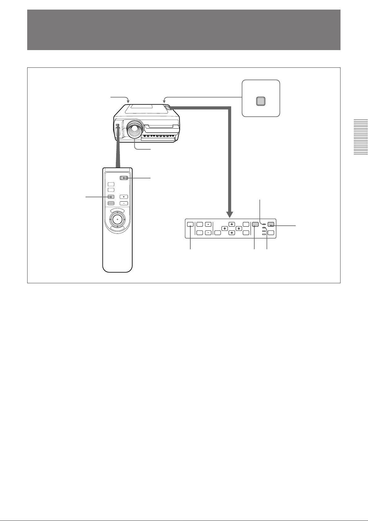
Location and Function of Controls
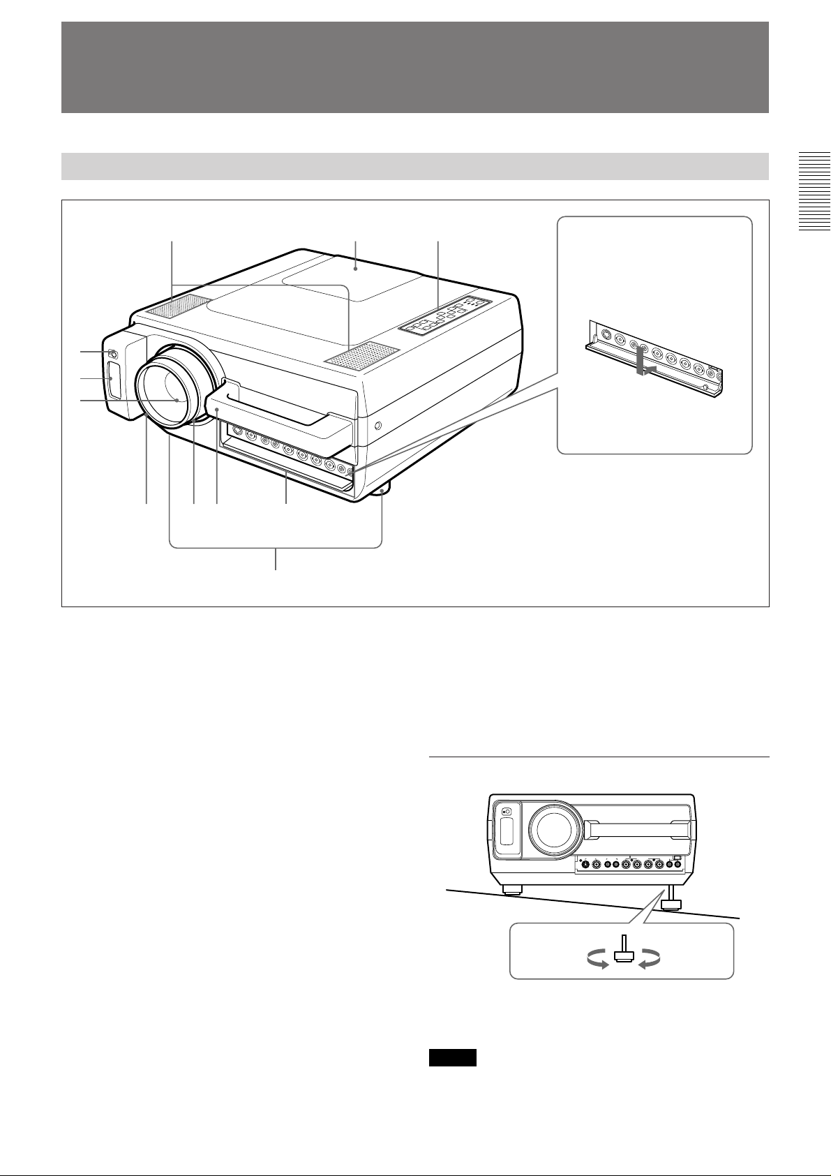
Front
1!`!…
2
3
4
567 9
8
1 Speakers
2 Front remote control detector
3 Remote Commander pocket
Houses the supplied Remote Commander. When
inserting the Remote Commander, make sure the
infrared transmitter is facing forwards and push it until
it clicks.
To take out the Remote Commander from the pocket,
push it once and pull it out.
How to open and close the
connector cover
To open the cover, pull it
down.
To close the cover, pull it up
until it locks.
9 Connector panel
For details, see page 9.
! ºControl panel
For details, see page 8.
! ¡ Lamp cover
How to use the adjusters
4 Lens
Remove the lens cap before projection.
5 Focus ring
Adjusts the picture focus.
6 Zoom ring
Adjusts the size of the picture.
7 Carrying handle
Use the handle for carrying the projector.
8 Adjusters
Use the adjusters to keep the projector level if it is
installed on an uneven surface.
To lower
the projector
To raise
the projector
While lifting the projector, turn the adjusters and
adjust the height so that the projector becomes level.
Note
Be careful not to let the projector down on your
fingers.
7 (EN)
Page 8

Location and Function of Controls
Control Panel
PATTERN PICTURE
MUTING VOLUME
AUDIO LIGHT
RESET
MENU
ENTER
INPUT
SELECT
POWER
STANDBY
u
3456789!…!`
LAMP
TEMP
POWER
1
2
1 POWER key
Press to turn the projector on and off once the
projector is in the standby mode. The POWER
indicator lights in green when the power is turned on.
When turning off the power, press and hold
the POWER key for about one second.
2 LIGHT key
Lights the back lighting (orange) for the control panel
when the power is turned on. Press again to turn off
the back lighting.
3 Indicators
POWER: Lights in green when the power is turned
on. Flashes in green while the cooling fan runs
after turning off the power with the POWER key.
The fan runs for about 1 minute and 30 seconds
after turning off the power. The POWER indicator
flashes quickly for the first minute. During this
time, you will not be able to turn the power back
on with the POWER key.
STANDBY: Lights in red when the MAIN POWER
switch at the rear of the projector is turned on.
Once in the standby mode, you can turn the
projector on and off with the POWER key on the
control panel or the Remote Commander.
TEMP (Temperature): Lights up or flahes under
the following conditions:
• Lights up when temperature inside the projector
becomes unusually high.
• Flashes when the fan inside the projector stops.
For details on the LAMP and the TEMP indicators, see page
34.
4 INPUT SELECT key
Selects the input signal. Each time the key is pressed,
signal from equipment connected to VIDEO IN and
INPUT-A connectors is selected alternately.
5 MENU key
Press to display the on-screen menu. Press again to
clear the menu.
6 ENTER key
Press to enter the settings of items in the menu system.
7 Arrow keys (V/v/B /b)
Used to move the on-screen cursor or to make various
adjustments.
8 RESET key
Press to restore the value of an item back to its factory
preset value. This key functions when the menu or a
setting item is displayed on the screen.
Note
When the MAIN POWER switch is turned off,
there will be a slight delay before the indicator goes
off.
LAMP: Lights up or flashes under the following
conditions:
• Lights up when a trouble has prevented the lamp
from lighting.
• Flashes when the lamp cover or air filter cover is
not secured firmly.
Note
When the LAMP indicator lights up, never open the
lamp cover if the projector is installed on the
ceiling.
8 (EN)
9 VOLUME +/– keys
Adjust the volume of the built-in speakers and output
level of the AUDIO OUT connectors.
+ : Increases the volume.
– : Decreases the volume.
! ºMUTING keys
Cuts off the picture and sound.
PICTURE: Press to cut off the picture. Press again to
restore the picture.
AUDIO: Press to cut off the sound. Press again or
press the VOLUME + key to restore the sound.
! ¡ PATTERN key
Display a pattern on the screen for focus adjustment.
Press again to clear the pattern.
Page 9
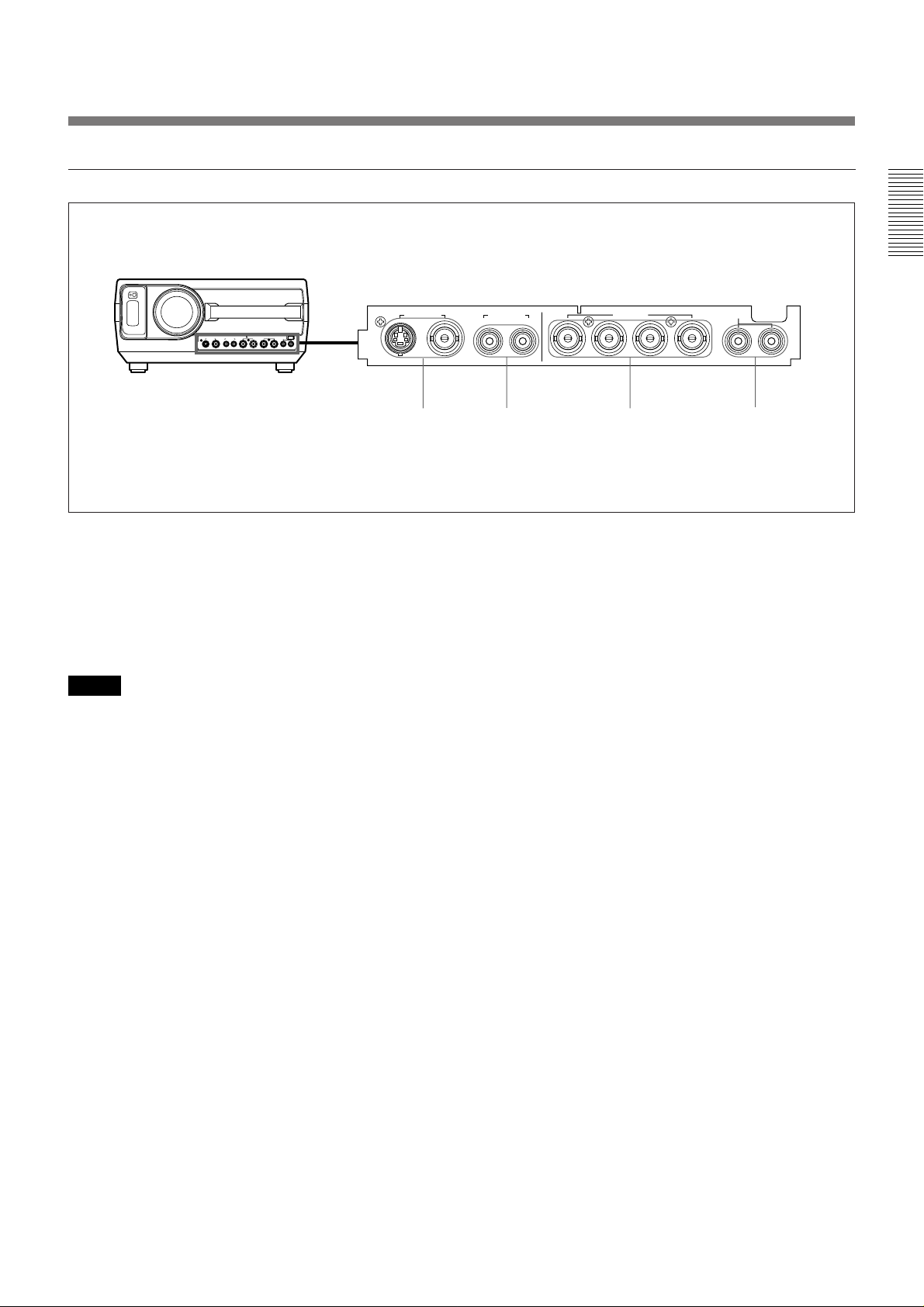
Connector Panel
VIDEO IN AUDIO IN
VIDEO IN
S VIDEO VIDEO
12 3
1 VIDEO IN connectors
S VIDEO (mini DIN 4-pin): Connects to the S
video output (Y/C video output) of a video
equipment.
VIDEO (BNC-type): Connects to the composite
video output of video equipment.
Note
If you have video equipments connected to both the S
VIDEO and VIDEO connectors, the signal from the S
VIDEO is selected. When showing video connected to
the VIDEO connector, be sure not to connect a cable to
the S VIDEO connector.
AUDIO IN
L (MONO)
R
L (MONO)
INPUT-A
R/R-Y/PRG/Y B/B-Y/PBC.SYNC
R
4
3 INPUT-A connectors (BNC-type)
R/R-Y/P
R, G/Y, B/B-Y/PB, C. SYNC connectors
Connect to the RGB output of the equipment.
4 AUDIO IN L (MONO)/R jacks (phono type)
When you connect the equipment to the INPUT-A
connectors, connect to the audio output jacks of the
equipment. For stereo equipment, use both the L and
R jacks; for monaural equipment, use the L (MONO)
jack only.
2 AUDIO IN L (MONO)/R jacks (phono type)
When you connect the equipment to the VIDEO IN
connectors, connect to the audio output jacks of the
equipment. For stereo equipment, use both the L and R
jacks; for monaural equipment, use the L (MONO)
jack only.
9 (EN)
Page 10
Location and Function of Controls
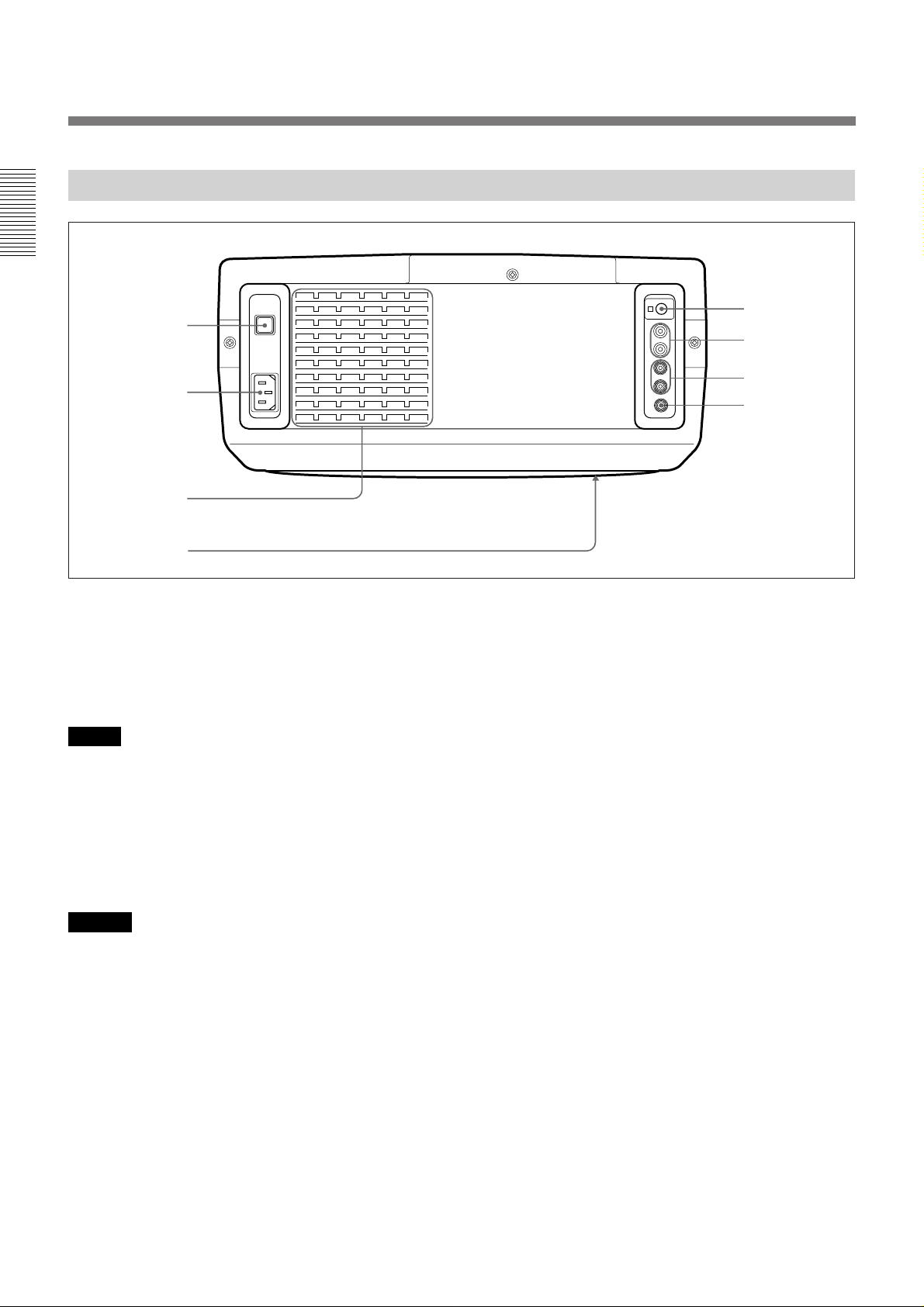
Rear
1
5
6
2
3
4
1 MAIN POWER switch (OON/oOFF)
Turns the main power on and off.
2 AC IN socket
Connect the supplied AC Power cord.
Note
If the supplied AC power cord plug does not match the
wall socket in your country, consult qualified Sony
personnel.
3 Ventilation holes (exhaust)
7
8
5 Rear remote control detector
6 AUDIO OUT L/R jacks (phono type)
Connects to external active speakers.
The volume of the speakers can be controlled by the
VOLUME keys on the projector or the Remote
Commander.
7 CONTROL S IN/OUT jack (stereo minijack)
Connect to the CONTROL S connectors of other Sony
equipment. It is then possible to control the whole
system with a single Remote Commander.
4 Ventilation holes (intake)
Notes
• Do not place anything near the ventilation holes as it
may cause internal heat build-up.
• Do not place your hand or objects near the
ventilation holes —the air coming out is hot.
10 (EN)
8 TRIG (trigger) connector (minijack)
Outputs the ON or OFF condition of the unit to the
external equipment.
When the unit is turned off, 0 V is output and when the
unit is turned on, 5 V is output. However, as the power
is not output, you cannot use the connector as the
power source.
Page 11
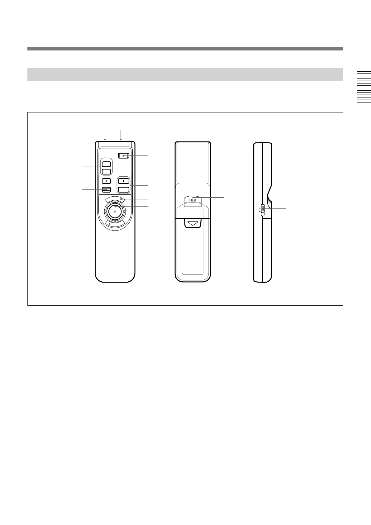
Remote Commander
The Remote Commander may be used as a wireless or
wired Remote Commander.
12
!…
9
8
MUTING
PIC
AUDIO
INPUT
POWER
VOLUMERESET
N
U
E
M
3
4
5
6
E
R
N
E
7
T
For details on operation of the keys not mentioned
here, see the description in the Control Panel section.
7
!`
MOUSE MENU
Front Rear Side
1 CONTROL S OUT connector (stereo
minijack)
Connect to the CONTROL S IN connector on the
projector when using the Remote Commander as a
wired Remote Commander.
2 Infrared transmitter
3 POWER key
4 VOLUME +/– keys
5 MENU key
6 Joy stick
Used to move the on-screen cursor or to make various
adjustments.
7 ENTER keys
8 RESET key
9 INPUT key
! º MUTING keys
! ¡ MOUSE/MENU switch
Set to MENU for this unit.
11 (EN)
Page 12
Location and Function of Controls
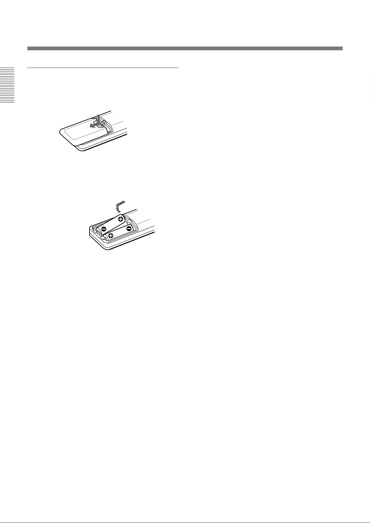
Battery installation
1 Push and slide to open the lid.
2 Install the two size AA (R6) batteries (supplied)
with the correct polarity.
Be sure to install
the battery from
the ’ side.
•The remote control detectors on the projector do not
operate when the Remote Commander is being used
as a wired Remote Commander. If you wish to use
the Remote Commander as a wireless Remote
Commander, be sure to remove the connecting cable
from both the Remote Commander and the projector.
3 Replace the lid.
Notes on batteries
• Be careful that the battery orientation is correct when
inserting batteries.
• Do not mix old battery with new one, or different
types of batteries.
• If you do not intend to use the Remote Commander
for a long time, remove the batteries to avoid damage
from battery leakage. If a battery has leaked, remove
the batteries, wipe the battery compartment dry and
replace the batteries with new ones.
Notes on wireless Remote Commander
operation
• Be sure that there is nothing to obstruct the infrared
beam between the Remote Commander and the
projector.
• The operation range is limited. The shorter the
distance between the Remote Commander and the
projector, the wider the angle within which the
commander can control the projector.
12 (EN)
Page 13
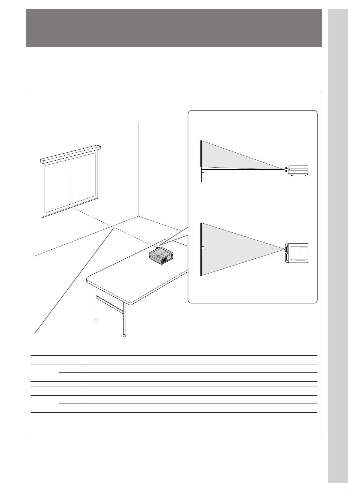
Installing the Projector
This section describes the installation arrangements for installing the
projector on a table. For ceiling installation, consult with qualified Sony
personnel (see page 31).
Horizontal center
of the screen
Setting up and projecting
Adjust the vertical and horizontal positioning of the
projector.
Vertical positioning (side view)
Adjust the height of the projector so that the center of
the lens is just below the bottom edge of the screen.
Horizontal positioning (top view)
Adjust the horizontal positioning of the projector so
that the lens is aligned with the horizontal center of the
screen.
The distance between the lens and the
screen varies depending on the size of the
screen. Use the following table as a guide.
16:9 screen size (inches) 41 60 80 100 120 150 180 200 250 300
Distance
Minimum 1.5 (4.9) 2.2 (7.3) 3.0 (9.8) 3.8 (12.4) 4.5 (14.9) 5.7 (18.7) 6.9 (22.5) 7.6 (25.1) 9.6 (31.4) 11.5 (37.7)
Maximum 2.3 (7.5) 3.4 (11.2) 4.6 (15.0) 5.7 (18.8) 6.9 (22.7) 8.7 (28.4) 10.4 (34.2) 11.6 (38.0) 14.5 (47.6) 17.5 (57.3)
Unit: m (feet)
4:3 screen size (inches) 34 60 80 100 120 150 180 200 245
Distance
Minimum 1.5 (5.0) 2.7 (9.0) 3.7 (12.1) 4.6 (15.2) 5.6 (18.3) 7.0 (23.0) 8.4 (27.6) 9.4 (30.7) 11.5 (37.7)
Maximum 2.3 (7.6) 4.2 (13.7) 5.6 (18.4) 7.1 (23.1) 8.5 (27.8) 10.6 (34.9) 12.8 (41.9) 14.2 (46.6) 17.4 (57.2)
For detailed information on installation measurements, see page 30.
13 (EN)
Page 14

Connecting with a VCR
This section describes how to connect the projector with a VCR and
external active speakers. For details on how to connect other equipment,
see page 32.
Also refer to the instruction manuals of the equipment to be connected.
When making connections, be sure to:
•turn off all equipment before making any connections.
•use the proper cables for each connection.
•insert the plugs of the cables properly; plugs that are not fully inserted
often generate noise. When pulling out a cable, be sure to pull it out from
the plug, not the cable itself.
Active speakers
Rear
to a wall outlet to AC IN
AC power cord
(supplied)
S-Video cable (not supplied)
Front
VIDEO IN AUDIO IN
VIDEO IN
S VIDEO VIDEO
L (MONO) R
AUDIO OUT
L
R
CONTROL S
IN
PLUG
IN POWER
OUT
TRIG
INPUT-A
R/R-Y/PRG/Y B/B-Y/PBC.SYNC
Audio cable
(not supplied)
AUDIO IN
LR
14 (EN)
to
to S VIDEO OUT to AUDIO OUT
VIDEO
OUT
Video cable (not supplied)
VCR
1)
1)
When using the video cable with
the phono plug, attach the supplied
BNC-phono adaptor.
Phono plug Adaptor (supplied)
Page 15
Projecting
Rear remote control
detector
Front remote control
detector
3
MUTING
AUDIO
INPUT
1
MAIN
POWER
O ON ⁄ o OFF
5
POWER
PIC
VOLUMERESET
N
E
U
M
E
N
R
T
E
2
PATTERN PICTURE
MUTING VOLUME
RESET
AUDIO LIGHT
MENU
ENTER
4
POWER indicator
POWER
INPUT
POWER
SELECT
STANDBY
u
LAMP
TEMP
STANDBY indicator
3
2
1 Press the MAIN POWER switch on the rear of the projector (O ON).
The STANDBY indicator lights in red and the projector goes into the
standby mode.
2 Press the POWER key on the Remote Commander or the control
panel.
The POWER indicator lights in green.
3 Switch on equipment connected to the projector. Press the INPUT
SELECT key on the control panel or the INPUT key on the Remote
Commander to select the input source.
INPUT-A: Selects signal input from the INPUT-A and AUDIO IN L/
R connectors.
VIDEO: Selects signal input from the VIDEO IN and AUDIO IN L/
R connectors.
(If you have made connections to both the S VIDEO and
the VIDEO connectors, the signal from S VIDEO
connector is selected.)
(continued)
15 (EN)
Page 16

Projecting
4 Press the PATTERN key on the control panel to display the “H” test
pattern, and turn the focus ring to adjust the focus.
HHHH HHHH
HHHH HHHH
HHHH
HHHH
HHHH HHHH
HHHH HHHH
Press the PATTERN key again to clear the pattern.
5 Turn the zoom ring to adjust the size of the picture.
Note
Do not look into the lens when the projector lamp is on.
To Press
Changing the picture mode
Adjust the volume the VOLUME +/– keys.
Cut off the sound the AUDIO MUTING key. To restore
the sound, press the AUDIO MUTING
key again or press the VOLUME + key.
Cut off the picture the PICTURE MUTING key (PIC
MUTING key on the Remote
Commander). To restore the picture,
press the PICTURE MUTING key
again.
You can change the picture mode according to the picture to be used or the
video signal.
1 Press the MENU key to display the menu.
2 Press the V/v keys on the control panel to select ASPECT SELECT,
then press the b key or the ENTER key.
VIDEO
AUTO WIDE:OFF
INPUT
SELECT
ASPECT:SUB TITLE
MEMORY
SELECT
V SCROLL: 0
TITLE AREA: 4
ASPECT
SELECT
SET
SETTING
INPUT
INFO.
SEL: EXIT: MENU
16 (EN)
3 Make setting or adjustment on an item.
For details on setting individual items, see page 24.
Page 17
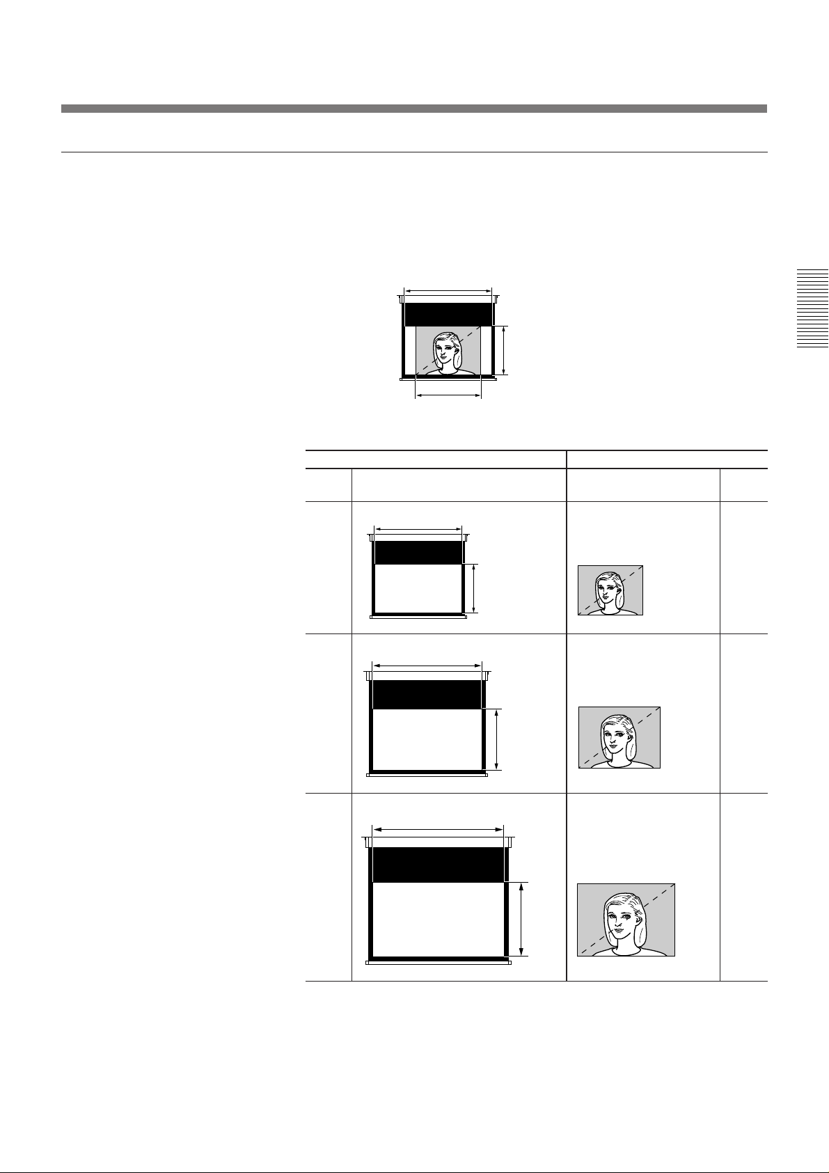
The picture size for the screen size
Refer to the followings for selecting the screen mode.
When the 4:3 picture is displayed on the 16:9 screen
Example: The 120 inch screen is used.
size
(inch)
90 73
2,656
1,494
1,992
The 98 inch picture is displayed.
16:9 screen 4:3 picture
unit: mm
1,992
unit: mm
1,494
size
(inch)
1,121
110 90
2,435
1,370
1,121
1,826
1,370
120 98
2,656
1,992
1,494
1,494
17 (EN)
Page 18
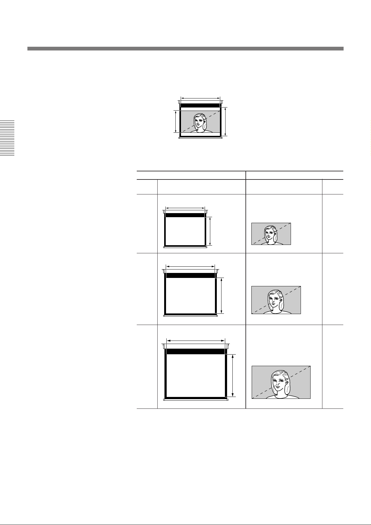
Projecting
When the 16:9 picture is displayed on the 4:3 screen
Example: The 120 inch screen is used.
2,438
1,8291,371
The 110 inch picture is displayed.
4:3 screen 16:9 picture
size
(inch)
80 73
1,626
unit: mm
unit: mm
1,626
size
(inch)
1,219
100 91
2,032
2,032
1,524
914,6
1,143
120 110
2,438
2,438
1,829
1,371
18 (EN)
Page 19

To turn off the power
1 Press and hold the POWER key on the control panel or the Remote
Commander for about one second.
The POWER indicator flashes in green and the fan continues to run for
about 1 minute and 30 seconds to reduce the internal heat. The
POWER indicator flashes quickly for the first minute. During this
time, you will not be able to turn the power back on with the POWER
key. After about one minute, you can turn on the power with the
POWER key.
2 Wait until the fan stops running and the STANDBY indicator lights in
red; then press the MAIN POWER switch to turn off the main power
(o OFF).
Notes
• Do not to press the MAIN POWER switch while the fan is still
running; the fan will stop while the lamp is still hot, leading to
breakdown.
• To make the lamp life last longer, do not turn off the power at
least for about 10 minutes after turning on the power.
Note on changing picture modese
This projector provides you with the various choices of picture modes.
Please select a picture mode taking into account that one which changes
the aspect ratio of the original picture will provide a different look from
that of the original image.
Please also note that if the projector is used for profit or for public
viewing, modifying the original picture by switching picture modes may
constitute an infringement of the rights of authors or producers which are
legally protected by laws.
19 (EN)
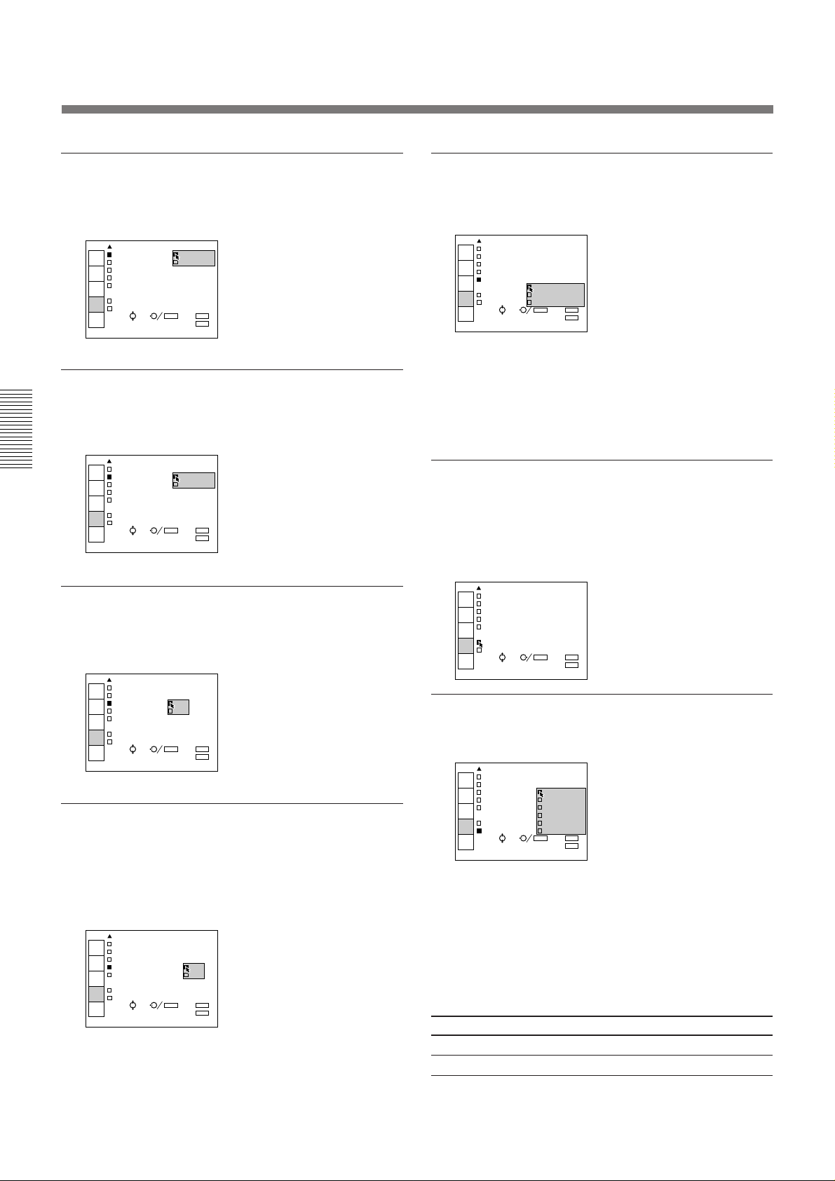
Page 20
Using the menu
The projector is equipped with an on-screen menu for
making various adjustments and settings.
To select the language used in the menu, see page
27.
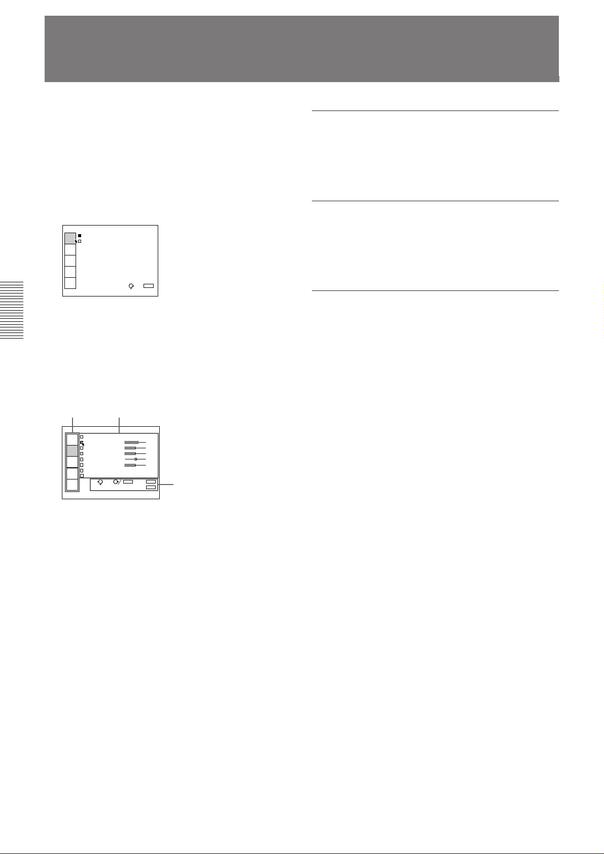
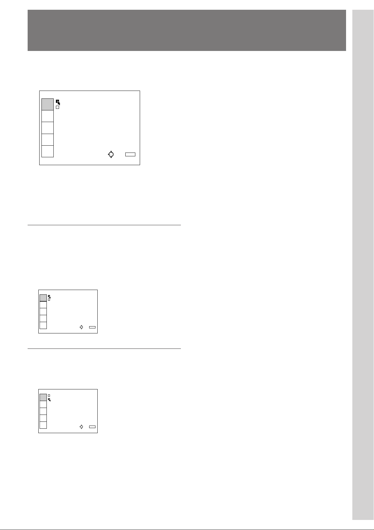
1 Press the MENU key.
The menu display appears.
The menu presently selected is highlighted in blue.
VIDEO
VIDEO
INPUT
SELECT
INPUT-A
MEMORY
SELECT
ASPECT
SELECT
SET
SETTING
INPUT
INFO.
SEL: EXIT: MENU
2 Use the V or v keys on the control panel to select a
menu, then press the b key or the ENTER key. On
the Remote Commander, move the joy stick up or
down to select a menu, then move it to the right or
press the ENTER key.
The selected menu appears.
To clear the menu display
Press the MENU key.
The menu display disappears automatically if no key is
pressed for one minute.
To reset items that have been adjusted
Press the RESET key. “RESET complete!” appears on
the screen and the settings appearing on the screen will
be reset to their factory preset values.
About the memory of the settings
The settings are automatically stored in the projector
memory.
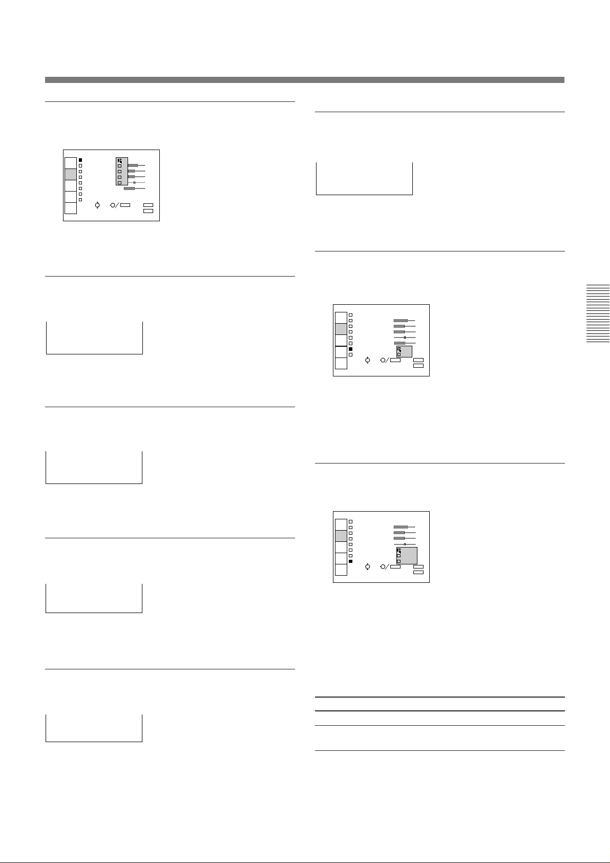
Menus Setting items
VIDEO
MEMORY:1
INPUT
SELECT
CONTRAST 80
BRIGHT 50
MEMORY
SELECT
COLOR 50
HUE 50
ASPECT
SELECT
SHARP 50
D.PICTURE:OFF
SET
SETTING
COLOR TEMP:LOW
SEL: SET: ENTER RESET: RESET
INPUT
INFO.
EXIT: MENU
Guide for operation
3 Make setting or adjustment on an item.
For details on setting individual items, see the relevant
menu pages.
20 (EN)
Page 21
VIDEO
VIDEO
INPUT-A
INPUT
SELECT
MEMORY
SELECT
ASPECT
SELECT
SET
SETTING
INPUT
INFO.
EXIT: MENU
SEL: EXIT: MENU
The INPUT SELECT Menu
O
INPUT-A
VIDEO
INPUT-A
INPUT
SELECT
MEMORY
SELECT
ASPECT
SELECT
SET
SETTING
INPUT
INFO.
EXIT: MENU
SEL:
The INPUT SELECT menu is used for selecting the
input signal.
VIDE
VIDEO
INPUT
SELECT
INPUT-A
MEMORY
SELECT
ASPECT
SELECT
SET
SETTING
INPUT
INFO.
Operation
Use the V or the v key on the control panel to select
the input, then press B key.
On the Remote Commander, move the joy stick up or
down to select the input, then move it to the left.
EXIT: MENU
SEL:
Adjustments and settings using the menu
VIDEO
Selects signal input from the VIDEO IN (S VIDEO or
VIDEO) connectors and the AUDIO IN L/R (for
VIDEO IN) connectors. If you have equipment
connected to both the VIDEO and the S VIDEO
connectors, the S VIDEO will be selected.
INPUT-A
Selects signal input from the INPUT-A and AUDIO
IN L/R (for INPUT-A) connectors.
21 (EN)
Page 22

O
0
0
0
0
0
The MEMORY SELECT Menu
INPUT
SELECT
MEMORY
SELECT
ASPECT
SELECT
SET
SETTING
INPUT
INFO.
SEL:
EXIT: MENU
SET: ENTER RESET: RESET
VIDEO
MEMORY: 1
CONTRAS 2 80
BRIGHT 3 50
COLOR 4 50
HUE 5 50
SHARP 50
D.PICTURE:OFF
COLOR TEMP:LOW
The MEMORY SELECT menu is used for adjusting
the picture. Items which can be adjusted are displayed
in green.
VIDE
MEMORY:1
INPUT
SELECT
CONTRAST 8
BRIGHT 5
MEMORY
SELECT
COLOR 5
HUE 5
ASPECT
SELECT
SHARP 5
D.PICTURE:OFF
SET
SETTING
COLOR TEMP:LOW
INPUT
INFO.
EXIT: MENU
SEL:
Operation
When changing the adjustment level:
1. Select an item.
Use the V or the v key on the control panel to select an
item, then press the b or the ENTER key.
On the Remote Commander, move the joy stick up or
down to select an item, then move it to the right or
press the ENTER key.
The selected item is dislayed at the bottom.
When changing the setting:
1. Select an item.
Use the V or the v key on the control panel to select an
item, then press the b or the ENTER key.
On the Remote Commander, move the joy stick up or
down to select an item, then move it to the right or
press the ENTER key.
The pop-up menu for the selected item appears.
2. Change the setting.
Press the V or the v key on the control panel.
On the Remote Commander, move the joy stick up or
down.
3. Press the ENTER or the B key on the
control panel to restore the original screen.
On the Remote Commander, press the ENTER key or
move the joy stick to the left.
CONTRAST: 80
2. Change the adjustment level.
To increase the number, press the V or the b key.
On the Remote Commander, move the joy stick up or
to the right.
To decrease the number, press the v or the B key.
On the Remote Commander, move the joy stick down
or to the left.
Adjustable range is MIN, 1, 2, … 98, 99, MAX.
3. Press the ENTER key to restore the original
screen.
The original screen is restored.
22 (EN)
Page 23
VIDEO
MEMORY:1
CONTRAST 80
BRIGHT 50
COLOR 50
HUE 50
SHARP HIGH 50
D.PICTURE: LOW
COLOR TEMP HBM
INPUT
SELECT
MEMORY
SELECT
ASPECT
SELECT
SET
SETTING
INPUT
INFO.
SEL: SET: ENTER RESET:
EXIT: MENU
RESET
MEMORY
INPUT
SELECT
MEMORY
SELECT
ASPECT
SELECT
SET
SETTING
INPUT
INFO.
SEL:
EXIT: MENU
SET: ENTER RESET: RESET
VIDEO
MEMORY: 1
CONTRAS 2 80
BRIGHT 3 50
COLOR 4 50
HUE 5 50
SHARP 50
D.PICTURE:ON
COLOR TEMP:HIGH
VIDEO
MEMORY:1
CONTRAST 80
BRIGHT 50
COLOR 50
HUE 50
SHARP 50
D.PICTURE ON
COLOR TEMP OFF
INPUT
SELECT
MEMORY
SELECT
ASPECT
SELECT
SET
SETTING
INPUT
INFO.
SEL: SET: ENTER
EXIT: MENU
RESET: RESET
Selects the memory number.
The adjusted data are memorized in MEMORY 1 to 5
for each of VIDEO IN and INPUT-A.
SHARP
Adjusts the picture sharpness.
SHARP: 80
The higher the setting, the sharper the picture.
The lower the setting, the softer the picture.
D. (Dynamic) PICTURE
CONTRAST
Adjusts the picture contrast.
CONTRAST: 80
The higher the setting, the greater the contrast.
The lower the setting, the lower the contrast.
BRIGHT
Adjusts the picture brightness.
BRIGHT: 50
The higher the setting, the brighter the picture.
The lower the setting, the darker the picture.
COLOR
Adjusts color intensity.
Emphasizes the dark portion of the picture.
ON: Emphasizes the dark portion of the picture to
produce a bolder “dynamic” picture.
OFF: Reproduces the dark portions of the picture
accurately, in accordance with the source signal.
COLOR TEMP
Adjust the color temperature.
COLOR: 50
The higher the setting, the greater the intensity.
The lower the setting, the lower the intensity.
HUE
Adjusts skin tones.
HUE: 50
A higher the setting, the picture becomes greenish.
A lower the setting, the picture becomes purplish.
HIGH: Makes the white color bluish.
LOW: Makes the white color reddish.
HBM (high brightness mode): Reproduces a
picture with high brightness.
The following items cannot be adjusted
depending on the types of input signal
Item Cannot be adjusted with
COLOR black-and-white signal
HUE Input signal other than NTSC 3.58/4.43 and
HDTV signals
23 (EN)
Page 24

The ASPECT SELECT Menu
O
VIDEO
AUTO WIDE: ON
ASPECT:SUB OFFLE
V SCROLL:+20
TITLE AREA:0
INPUT
SELECT
MEMORY
SELECT
ASPECT
SELECT
SET
SETTING
INPUT
INFO.
SEL: SET:
ENTER RESET:
EXIT: MENU
RESET
VIDEO
AUTO WIDE: ON
ASPECT:SUB OFFLE
V SCROLL:+20
TITLE AREA:0
INPUT
SELECT
MEMORY
SELECT
ASPECT
SELECT
SET
SETTING
INPUT
INFO.
SEL: SET:
ENTER RESET:
EXIT: MENU
RESET
V SCROLL: +20
The ASPECT SELECT menu is used to set the picture
mode.
VIDE
AUTO WIDE:OFF
INPUT
SELECT
ASPECT:SUB TITLE
MEMORY
SELECT
V SCROLL: 0
TITLE AREA: 4
ASPECT
SELECT
SET
SETTING
INPUT
INFO.
SEL:
EXIT: MENU
Operation
When changing the adjustment level:
1. Select an item.
Use the V or the v key on the control panel to select
the item, then press the b or the ENTER key.
On the Remote Commander, move the joy stick up or
down to select the item, then move it to the right or
press the ENTER key.
The selected item is dislayed at the bottom.
When changing the setting:
1. Select an item.
Use the V or the v key on the control panel to select
the item, then press the b or the ENTER key.
On the Remote Commander, move the joy stick up or
down to select the item, then move it to the right or
press the ENTER key.
The pop-up menu for the selected item appears.
2. Change the setting.
Press the V or the v key on the control panel.
On the Remote Commander, move the joy stick up or
down.
3. Press the ENTER or the B key on the
control panel to restore the original screen.
On the Remote Commander, press the ENTER key or
move the joy stick to the left.
2. Change the adjustment level.
To increase the number, press the V or the b key.
On the Remote Commander, move the joy stick up or
to the right.
To decrease the number, press the v or the B key.
On the Remote Commander, move the joy stick down
or to the left.
3. Press the ENTER key to restore the original
screen.
The original screen is restored.
24 (EN)
AUTO WIDE
Selects the AUTO WIDE mode.
ON: The picture automatically switches to wide-
screen mode (ZOOM or SUB TITLE) when a
letter box signal is received.
When an ID-1 signal is received, the picture is
automatically set to FULL or ZOOM.
OFF: The AUTO WIDE function does not work.
Note
The AUTO WIDE function may not work correctly
depending on a video signal. In this case, set the
AUTO WIDE function to OFF.
Page 25
ASPECT
VIDEO
AUTO WIDE:OFF
ASPECT: NORMAL
FULL
V SC ZOOM
TITL SUB TITLE
WIDE ZOOM
INPUT
SELECT
MEMORY
SELECT
ASPECT
SELECT
SET
SETTING
INPUT
INFO.
SEL: SET:
ENTER
EXIT: MENU
RESET: RESET
V SCROLL: +20
TITLE AREA: 4
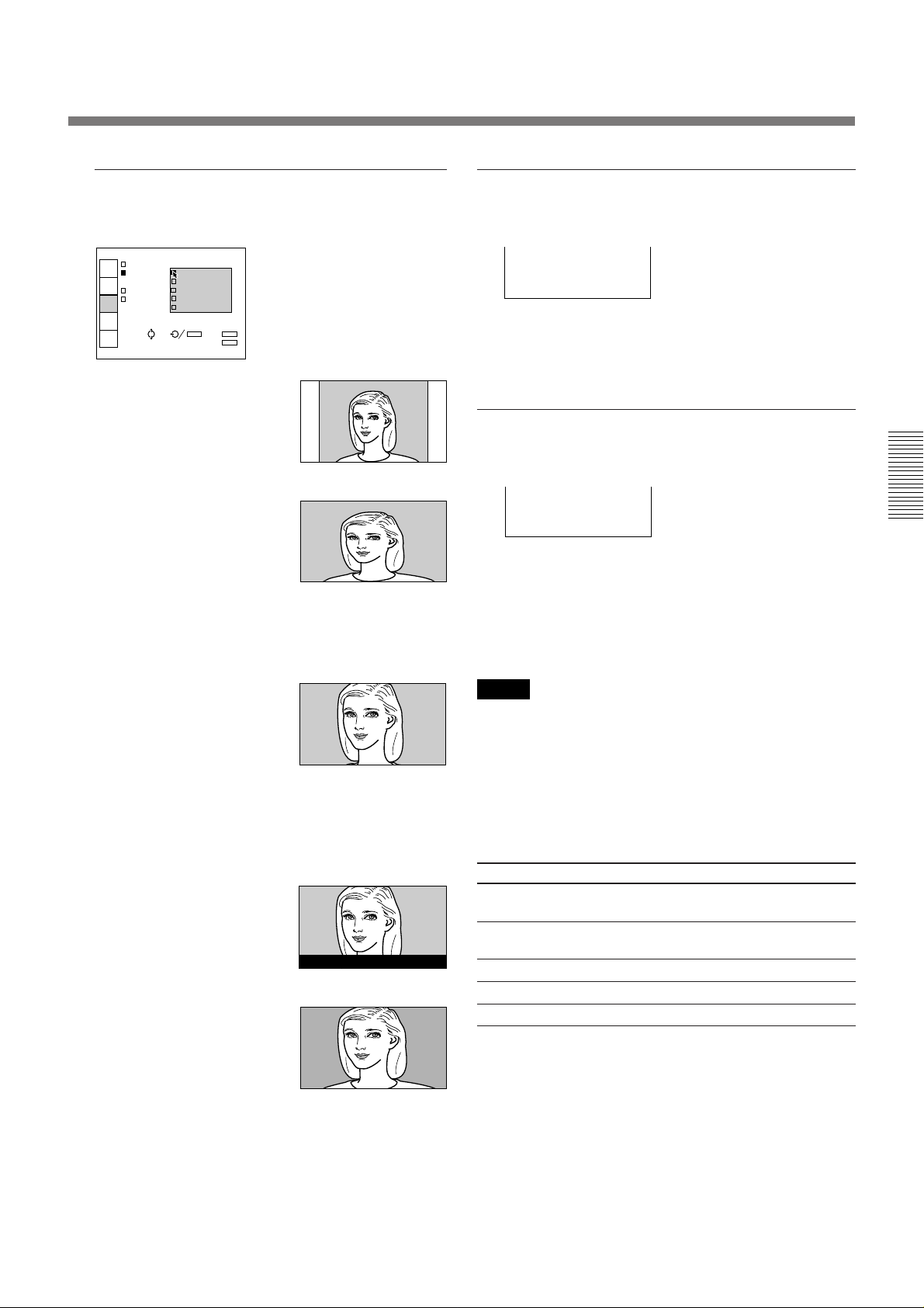
V SCROLL
Sets the aspect ratio.
NORMAL: The picture
with normal ratio 4:3 is
displayed.
FULL: The picture with
normal ratio 4:3 is
enlarged horizontally.
This mode brings a new
level of excitement to
video games, making them
more involving and
challenging.
Adjusts the vertical position of the picture.
Adjustable range is –31 to +31.
As the setting increases, the picture moves up, and as
the setting decreases, the picture moves down.
To resume the normal position, press the RESET key.
TITLE AREA
Adjust the subtitle area.
Adjustable range is 0 to 8.
As the setting increases, the subtitle area becomes
wide, and as the setting decreases, the subtitle area
becomes narrow.
To resume the normal area, press the RESET key.
ZOOM: The picture with
normal ratio 4:3 is
enlarged vertically and
horizontally (with same
ratio) to the screen size.
This mode is ideal for
capturing the full-screen
drama of wide-format
movies.
SUB TITLE: The subtitle
area is compressed.
This mode leaves the
subtitles on the lower part
of the screen.
WIDE ZOOM: The
picture with normal ratio
4:3 is enlarged and the
upper and lower portions
of the picture are
compressed.
This is ideal for general
programs, such as news or
variety shows.
Good morning.
How are you?
Note
Although the adjustable range displayed is 0 to 8, the
actual range may be limited depending on the V
SCROLL setting.
The following item cannot be adjusted
depending on the types of input signal or the
selected aspect ratio
Item Cannot be adjusted with
ASPECT HDTV signal input from INPUT-A
SELECT menu connectors
AUTO WIDE RGB/Component signal input from INPUT-A
connectors
ASPECT when the AUTO WIDE is set to ON
V SCROLL NORMAL, FULL and WIDE ZOOM
TITLE AREA NORMAL, FULL, ZOOM and WIDE ZOOM
25 (EN)
Page 26

A
The SET SETTING Menu
A
INPUT-A
STATUS: ON
PIC.MUT OFF
AUDIO M ALL OFFF
SPEAKER:ON
INPUT-A:RGB
LANGUAGE:ENGLISH
INPUT
SELECT
MEMORY
SELECT
ASPECT
SELECT
SET
SETTING
INPUT
INFO.
SEL: SET: ENTER RESET:
EXIT: MENU
RESET
The SET SETTING menu is used for changing the
settings of the projector.
<page 1>
INPUT STATUS:ON
INPUT
SELECT
PIC.MUTING:OFF
AUDIO MUTING:OFF
MEMORY
SELECT
SPEAKER:ON
INPUT-A:RGB
ASPECT
SELECT
LANGUAGE:ENGLISH
SET
SETTING
INPUT
INFO.
EXIT: MENU
SEL:
<page 2>
INPUT H POLARITY:NORMAL
INPUT
SELECT
V POLARITY:NORMAL
HALF TONE:ON
MEMORY
SELECT
POWER SAVING:OFF
SIRCS RECEIVER:
ASPECT
SELECT
FRONT&REAR
PATTERN
SET
SETTING
COLOR SYS:AUTO
INPUT
INFO.
SEL: SET: ENTER RESET: RESET
EXIT: MENU
Operation
1. Select an item.
Use the V or the v key on the control panel to select
the item, then press the b or the ENTER key.
On the Remote Commander, move the joy stick up or
down to select the item, then move it to the right or
press the ENTER key.
The pop-up menu for the selected item appears.
2. Change the setting.
Press the V or the v key to change the setting.
On the Remote Commander, move the joy stick up or
down to change the setting.
3. Press the ENTER or the B key to restore the
original screen.
The SET SETTING menu consists of two pages.
To change the page, press the v or V the key until the
page changes when selecting an item.
On the Remote Commander, move the joy stick up or
down until the page changes when selecting an item.
26 (EN)
Page 27
INPUT-A
STATUS:OFF
PIC.MUTING:ON
AUDIO MUTING:OFF
SPEAKER:ON
INPUT-A: RGB
LANGUAGE COMPONENT
HDTV YPB PR
HDTV GBR
INPUT
SELECT
MEMORY
SELECT
ASPECT
SELECT
SET
SETTING
INPUT
INFO.
SEL: SET: ENTER RESET:
EXIT: MENU
RESET
INPUT-A
STATUS:OFF
PIC.MUTING:ON
AUDIO MUTING:OFF
SPEAKER: ON
INPUT-A: OFF
LANGUAGE:ENGLISH
INPUT
SELECT
MEMORY
SELECT
ASPECT
SELECT
SET
SETTING
INPUT
INFO.
SEL: SET: ENTER RESET:
EXIT: MENU
RESET
STATUS (on-screen display)
A
INPUT-A
STATUS:OFF
PIC.MUTIN ENGLISH
AUDIO MUT FRANCAIS
SPEAKER:O DEUTSCH
INPUT-A:C ITALIANO
LANGUAGE: ESPANOL
INPUT
SELECT
MEMORY
SELECT
ASPECT
SELECT
SET
SETTING
INPUT
INFO.
SEL: SET: ENTER RESET:
EXIT: MENU
RESET
SPEAKER
ON: Shows all of the on-screen displays.
OFF: Turns off the on-screen displays except for
“NO INPUT”, “PIC/AUDIO MUTING”, and
warning messages (see page 35.)
ALL OFF: Turns off all of the on-screen displays
except for warning messages.
INPUT STATUS: ON
INPUT
SELECT
PIC.MUT OFF
AUDIO M ALL OFFF
MEMORY
SELECT
SPEAKER:ON
INPUT-A:RGB
ASPECT
SELECT
LANGUAGE:ENGLISH
SET
SETTING
SEL: SET: ENTER RESET:
INPUT
INFO.
EXIT: MENU
RESET
PIC. MUTING
Set to ON to cut off the picture.
When set to ON, “PIC MUTING” appears on the
screen.
INPUT-A
STATUS:OFF
INPUT
SELECT
PIC.MUTING: ON
AUDIO MUTIN OFFF
MEMORY
SELECT
SPEAKER:ON
INPUT-A:RGB
ASPECT
SELECT
LANGUAGE:ENGLISH
SET
SETTING
INPUT
INFO.
SEL: SET: ENTER RESET:
EXIT: MENU
RESET
AUDIO MUTING
Set to OFF to cut off the sound of the internal
speakers. When set to OFF, “SPEAKER OFF” appears
on the screen when you turn on the power.
INPUT-A
Selects the RGB, COMPONENT, HDTV YPBPR or
HDTV GBR signal input from INPUT-A.
Note
Select the item according to the input signal. If the
setting is not correct, the picture may not be displayed
or may be incorrectly displayed.
Set to ON to cut off the sound.
When set to ON, “AUDIO MUTING” appears on the
screen.
INPUT-A
STATUS:OFF
INPUT
SELECT
PIC.MUTING:ON
AUDIO MUTING: ON
MEMORY
SELECT
SPEAKER:ON OFF
INPUT-A:RGB
ASPECT
SELECT
LANGUAGE:ENGLISH
SET
SETTING
SEL: SET: ENTER RESET:
INPUT
INFO.
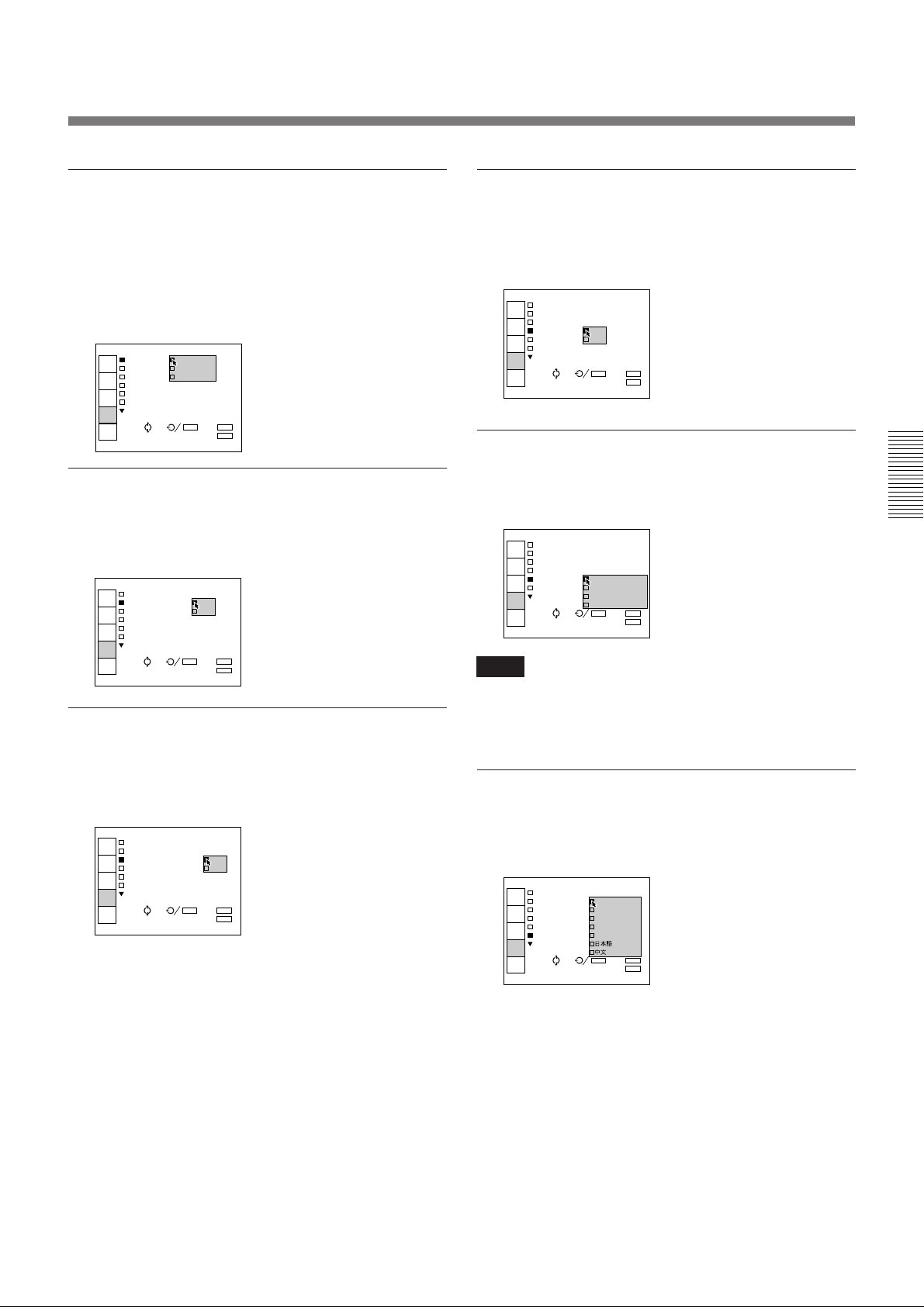
LANGUAGE
Selects the language used in the menu and on screen
displays.
RESET
EXIT: MENU
Available languages are: English, French, German,
Italian, Spanish, Japanese and Chinese.
(continued)
27 (EN)
Page 28
INPUT-A
H POLARITY:NORMAL
V POLARITY AUTO
HALF TONE: NTSC3.58
IR RECEIVE PAL
POWER SAVI SECAM
PATTERN NTSC4.43
COLOR SYS: PAL.M
INPUT
SELECT
MEMORY
SELECT
ASPECT
SELECT
SET
SETTING
INPUT
INFO.
SEL: SET: ENTER RESET:
EXIT: MENU
RESET
INPUT-A
H POLARITY:NORMAL
V POLARITY:NORMAL
HALF TONE:ON
POWER SAVING:OFF
SIRCS RECEIVER:
FRONT&REAR
PATTERN
COLOR SYS:AUTO
INPUT
SELECT
MEMORY
SELECT
ASPECT
SELECT
SET
SETTING
INPUT
INFO.
SEL: SET: ENTER RESET:
EXIT: MENU
RESET
INPUT-A
H POLARITY:NORMAL
V POLARITY:NORMAL
HALF TONE:ON
POWER SAVING:OFF
SIRCS RECEIVER:
FRONT&REAR
PATTERN FRONT
COLOR SY REAR
INPUT
SELECT
MEMORY
SELECT
ASPECT
SELECT
SET
SETTING
INPUT
INFO.
SEL: SET: ENTER RESET:
EXIT: MENU
RESET
The SET SETTING Menu
H (Horizontal) POLARITY
Set to REVERSE to reverse the horizontal orientation
of the picture.
INPUT-A
H POLARITY: NORMAL
INPUT
SELECT
V POLARITY: REVERSE
HALF TONE:ON
MEMORY
SELECT
POWER SAVING:OFF
SIRCS RECEIVER:
ASPECT
SELECT
FRONT&REAR
PATTERN
SET
SETTING
COLOR SYS:AUTO
SEL: SET: ENTER RESET:
INPUT
INFO.
EXIT: MENU
RESET
V (vertical) POLARITY
Set to REVERSE to reverse the vertical orientation of
the picture.
INPUT-A
H POLARITY:NORMAL
INPUT
SELECT
V POLARITY: NORMAL
HALF TONE:O REVERSE
MEMORY
SELECT
POWER SAVING:OFF
SIRCS RECEIVER:
ASPECT
SELECT
FRONT&REAR
PATTERN
SET
SETTING
COLOR SYS:AUTO
SEL: SET: ENTER RESET:
INPUT
INFO.
EXIT: MENU
RESET
SIRCS RECEIVER
Selects the remote control detectors on the front and
rear of the projector.
FRONT & REAR: Activates both the front and rear
detectors.
FRONT: Activates the front detector only.
REAR: Activates the rear detector only.
PATTERN
Press the b or the ENTER key to display the “H” test
pattern. Press the B or the ENTER key to clear the
pattern. The pattern disappears automatically if no key
is pressed for one minute.
HALF TONE
Set to ON to reduce the luminance of the menu
background.
INPUT-A
H POLARITY:NORMAL
INPUT
SELECT
V POLARITY:NORMAL
HALF TONE: ON
MEMORY
SELECT
POWER SAVI OFFFF
SIRCS RECEIVER:
ASPECT
SELECT
FRONT&REAR
PATTERN
SET
SETTING
COLOR SYS:AUTO
SEL: SET: ENTER RESET:
INPUT
INFO.
POWER SAVING
When set to ON, the projector goes into the power
saving mode if no signal is input for 10 minutes. The
power saving mode is canceled when a signal is input
or whenever a key is pressed.
INPUT-A
H POLARITY:NORMAL
INPUT
SELECT
V POLARITY:NORMAL
HALF TONE:ON
MEMORY
SELECT
POWER SAVING: ON
SIRCS RECEIVE OFF
ASPECT
SELECT
FRONT&REAR
PATTERN
SET
SETTING
COLOR SYS:AUTO
SEL: SET: ENTER RESET:
INPUT
INFO.
28 (EN)
EXIT: MENU
EXIT: MENU
COLOR SYS (system)
RESET
RESET
Selects the color system of the input signal.
Normally, set to AUTO.
If the picture is distorted or colorless, select the color
system according to the input signal.
The following item cannot be adjusted
depending on the types of input signal
Item Cannot be adjusted with
INPUT-A Signal input from VIDEO IN connectors
COLOR SYS Signal input from INPUT-A connectors
Page 29

The INPUT INFO Menu
O
The INPUT INFO menu displays the information on a
current input signal.
VIDE
fH:15.8kHz
INPUT
SELECT
fV:59.9Hz
C. SYNC:---
MEMORY
SELECT
SonG:-- INPUT SIGNAL:
ASPECT
SELECT
MEMORY SELECT: 1
SET
SETTING
INPUT
INFO.
NTSC3.58
SEL: EXIT: MENU
fH (Horizontal frequency)
Indicates the horizontal frequency of the input signal.
This indication is only used as a reference, this is not
absolute value.
fV (Vertical frequency)
Indicates the vertical frequency of the input signal.
This indication is only used as a reference, this is not
absolute value.
Note
If the setting for INPUT-A on the SET SETTING
menu is incorrect, or connection is not made properly,
the horizontal and vertical frequencies will be
indicated as “--.-”.
C. SYNC (Composite Sync)
Indicates the polarity of the composite sync. signal.
When the picture is being projected using its sync
signal, POS (NEG) is displayed in green. When the
picture is being projected without using sync signal,
POS (NEG) is displayed in white.
POS: The polarity of the sync. signal is positive.
NEG: The polarity of the sync. signal is negative.
---: No sync. signal is input.
SonG
Indicates the polarity of the Sync on Green. When the
picture is being projected using its sync signal, NEG is
displayed in green. When the picture is being projected
without using sync signal, NEG is displayed in white.
NEG: The polarity of the sync. signal is negative.
---: No Sync. signal is input.
INPUT SIGNAL
Displays the type of current input signal.
NTSC 3.58: NTSC 3.58 input signal from VIDEO
IN
NTSC 3.58 Y/C: NTSC 3.58 Y/C input signal from
VIDEO IN
NTSC 4.43: NTSC 4.43 input signal from VIDEO
IN
NTSC 4.43 Y/C: NTSC 4.43 Y/C input signal from
VIDEO IN
PAL: PAL input signal from VIDEO IN
PAL Y/C: PAL Y/C input signal from VIDEO IN
PAL-M: PAL-M input signal form VIDEO IN
PAL-M Y/C: PAL-M Y/C input signal form VIDEO
IN
SECAM: SECAM input signal from VIDEO IN
SECAM Y/C: SECAM Y/C input signal from
VIDEO IN
RGB: RGB input signal
COMPONENT: Component input signal
HDTV YP
BPR: HDTV YPBPR input signal
HDTV GBR: HDTV GBR input signal
B/W 50: Black and white input signal from VIDEO
IN (vertical frequency: 50 Hz)
B/W 60: Black and white input signal from VIDEO
IN (vertical frequency: 60 Hz)
MEMORY SELECT
The MEMORY SELECT number is displayed
Note
For composite sync, input the negative sync signal.
29 (EN)
Page 30
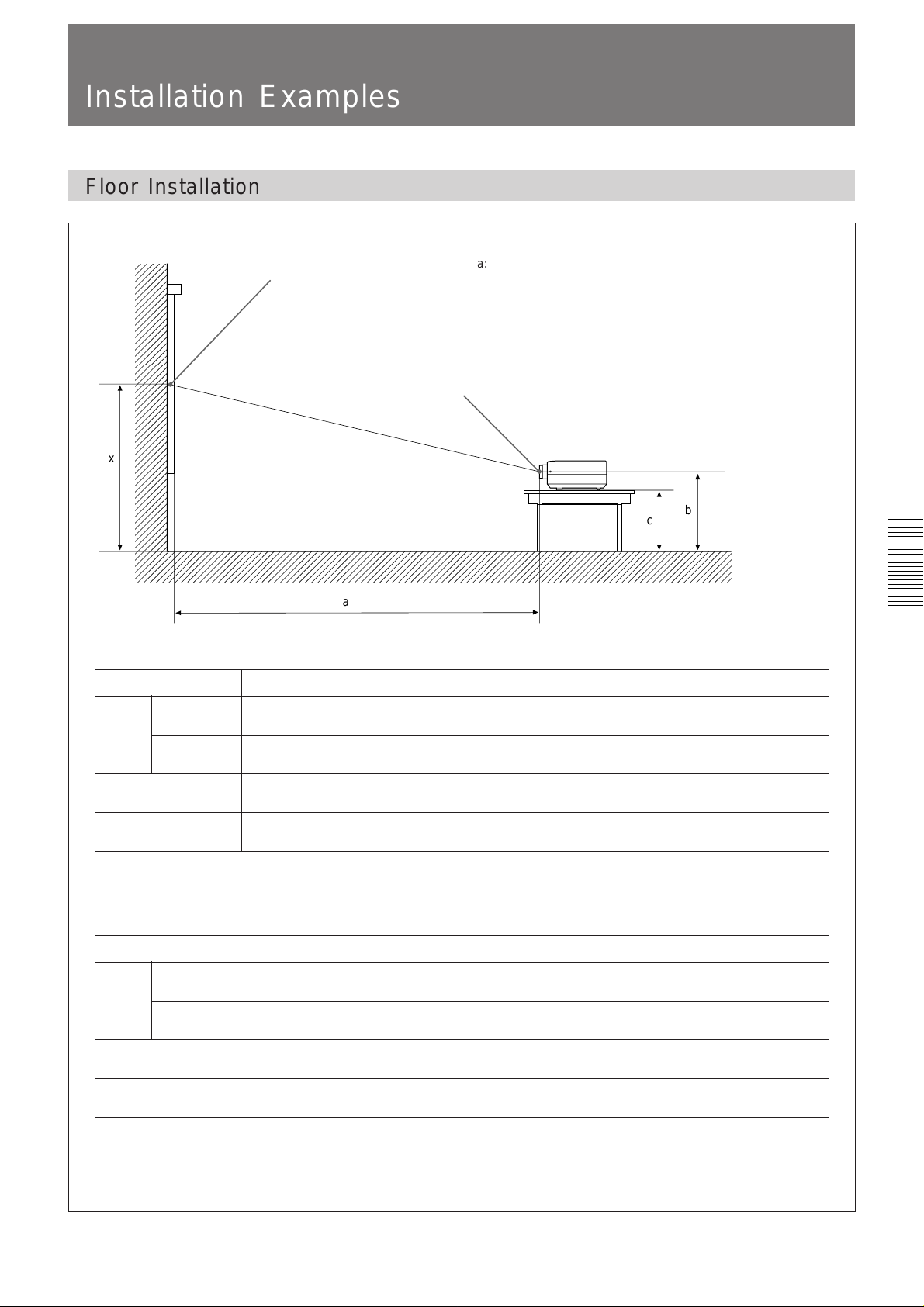
Installation Examples
Floor Installation
Wall
x
16:9 screen size (inches) 41 60 80 100 120 150 180 200 250 300
(mm)
a
(mm)
b
c
(mm)
To calculate the installation measurement (unit: mm*) a (minimum) = (SS – 2.6584) ÷ 26.501 × 1025
SS: screen size diagonal (inches) a (maximum) = (SS – 1.898) ÷ 16.656 × 975
Minimum
Maximum
Center of the screen
a
1490 2220 3000 3770 4540 5700 6860 7640 9570 11500
(58 3/4) (87 1/2) (118 1/8) (148 1/2) (178 3/4) (224 1/2) (270 1/8) (300 7/8) (376 7/8) (452 7/8)
2280 3400 4570 5740 6910 8660 10420 11590 14520 17450
(89 7/8) (133 7/8) (180) (226) (272 1/8) (341) (410 1/4) (456 3/8) (571 3/4) (687 1/8)
x–334 x–488 x–651 x–814 x–977 x–1221 x-1465 x–1628 x–2035 x–2442
(13 1/4) (19 1/4) (25 3/4) (32 1/8) (38 1/2) (48 1/8) (57 3/4) (64 1/8) (80 1/8) (96 1/4)
x–445 x–599 x–762 x–925 x–1088 x–1332 x-1576 x–1739 x–2146 x–2553
(17 5/8) (23 5/8) (30) (36 1/2) (42 7/8) (52 1/2) (62 1/8) (68 1/2) (84 1/2) (100 5/8)
b = X – (SS × 25.4 ÷ 34.323 × 11)
c = X – (SS × 25.4 ÷ 34.323 × 11 + 111)
a: distance between the screen and the center of the lens
b: distance from the floor to the center of the lens
c: distance from the floor to the foot of the projector
x: free
Center of the lens
b
c
Floor
Unit: mm (inches)
4:3 screen size (inches) 34 60 80 100 120 150 180 200 245
Minimum
a
(mm)
Maximum
b
(mm)
c
(mm)
To calculate the installation measurement (unit: mm*) a (minimum) = (SS – 2.1755) ÷ 21.653 × 1025
SS: screen size diagonal (inches) a (maximum) = (SS – 1.5484) ÷ 13.609 × 975
* When converting the number’s unit from mm to inch, divide it by 254.
1510 2740 3690 4630 5580 7000 8420 9370 11500
(59 1/2) (107 7/8) (145 3/8) (182 3/8) (219 3/4) (275 5/8) (331 1/2) (369) (452 7/8)
2320 4180 5620 7050 8480 10630 12780 14210 17440
(91 3/8) (164 5/8) (221 3/8) (277 5/8) (333 7/8) (418 5/8) (503 1/4) (559 1/2) (686 5/8)
x–339 x–598 x–797 x–996 x–1196 x–1494 x-1793 x–1993 x–2441
(13 3/8) (23 5/8) (31 1/2) (39 1/4) (47 1/8) (58 7/8) (70 5/8) (78 1/2) (96 1/8)
x–450 x–709 x–908 x–1107 x–1307 x–1605 x-1904 x–2104 x–2552
(17 3/4) (28) (35 3/4) (43 5/8) (51 1/2) (63 1/4) (75) (82 7/8) (100 1/2)
b = X – (SS × 25.4 ÷ 28.045 × 11)
c = X – (SS × 25.4 ÷ 28.045 × 11 + 111)
30 (EN)
Page 31

Ceiling Installation
For ceiling installation, consult with qualified Sony personnel.
a
Installation/connection Examples
Projector Suspension
Support PSS-500 (not supplied)
Ceiling
Center of the screen
c
Center of the lens
a: Distance between the screen and the center of lens
b: Distance between the ceiling and the center of the lens
c: Distance between the ceiling and the center of the screen
Wall
16:9 screen size (inches)
Minimum
a (mm)
Maximum
b (mm) 247 (9 3/4) / 272 (10 3/4) / 297 (11 3/4) / 347 (13 3/4) / 372 (14 3/4) / 397 (15 3/4) adjustable
c (mm)
To calculate the installation measurement (unit: mm*) a (minimum) = (SS – 2.6584) ÷ 26.501 × 1025
SS: screen size diagonal (inches) a (maximum) = (SS – 1.898) ÷ 16.656 × 975
60 80 100 120 150 180 200 250 300
2220 3000 3770 4540 5700 6860 7640 9570 11500
(87 1/2) (118 1/8) (148 1/2) (178 3/4) (224 1/2) (270 1/8) (300 7/8) (376 7/8) (452 7/8)
3400 4570 5740 6910 8660 10420 11590 14520 17450
(133 7/8) (180) (226) (272 1/8) (341) (410 1/4) (456 3/8) (571 3/4) (687 1/8)
b+488 b+651 b+814 b+977 b+1221 b+1465 b+1628 b+2035 b+2442
(19 1/4) (25 3/4) (32 1/8) (38 1/2) (48 1/8) (57 5/8) (64 1/8) (80 1/8) (96 1/4)
c = b + (SS × 25.4 ÷ 34.323 × 11)
b
Unit: mm (inches)
4:3 screen size (inches)
Minimum
a (mm)
Maximum
b (mm) 247(9 3/4) / 272 (10 3/4) / 297 (11 3/4) / 347 (13 3/4) / 372 (4 3/4) / 397 (15 3/4) adjustable
c (mm)
To calculate the installation measurement (unit: mm*) a (minimum) = (SS – 2.1755) ÷ 21.653 × 1025
SS: screen size diagonal (inches) a (maximum) = (SS – 1.5484) ÷ 13.609 × 975
* When converting the number’s unit from mm to inch, divide it by 254.
60 80 100 120 150 180 200 245
2740 3690 4630 5580 7000 8420 9370 11500
(107 7/8) (145 3/8) (182 3/8) (219 3/4) (275 5/8) (331 1/2) (369) (452 7/8)
4180 5620 7050 8480 10630 12780 14210 17440
(164 5/8) (221 3/8) (277 5/8) (333 7/8) (418 5/8) (503 1/4) (559 1/2) (686 5/8)
b+598 b+797 b+996 b+1196 b+1494 b+1793 b+1993 b+2441
(23 5/8) (31 1/2) (39 1/4) (47 1/8) (58 7/8) (70 5/8) (78 1/2) (96 1/8)
c = b + (SS × 25.4 ÷ 28.045 × 11)
31 (EN)
Page 32

Connection Example
For details on how to conncet a VCR or external active
Connecting a BNC connector:
speakers, see page 14. Also refer to the instruction
manual of the equipment to be connected.
When making connections, be sure to:
•Before connecting any cables, make sure that each
piece of equipment to be connected is turned off.
•Use cables appropriate for the equipment to be
connected.
•A loose connection may cause hum or noise.
•When disconnecting a cable, pull it out from the plug;
not the cable itself.
Connecting 15k RGB/Component Equipment
15k RGB/component equipment
to RGB/component output
2 Twist to the right.
1 Align the pins with the pin holes and
push in the plug into the socket.
HDVS
Front
to a wall outlet to AC IN
AC power cord
(supplied)
VIDEO IN AUDIO IN
VIDEO IN
S VIDEO VIDEO
L (MONO) R
Notes
• This unit cannot accept separate sync signal with 15k
RGB/component input signal. Use composite sync
(negative) or Sync on Green.
Connecting cable (not supplied)
INPUT-A
R/R-Y/PR G/Y B/B-Y/PB C.SYNC
AUDIO IN
LR
• Select the RGB, COMPONENT, HDTV signal
the INPUT-A item on the SET SETTING menu.
1)
with
..........................................................................................................................................................................................................
1) The picture may not be correctly displayed when an HDTV signal with external sync signal is input. To view the
HDTV signal, input the G signal with the sync signal or Y signal with the sycn signal, to the INPUT-A G/Y connector.
Do not connect the external sync signal to the INPUT-A C. SYNC connector.
32 (EN)
Page 33

Maintenance
.
Maintenance
Replacing the Lamp
When it is time to change the lamp, the message
“Please replace the LAMP” appears on the screen
when you turn on the projector. Once the message
appears, replace the lamp promptly with a new PKPJ500 lamp.
Please replace the LAMP
The message disappears if any key on the control panel
or the Remote Commander is pressd.
Notes
• If you continue to use the projector after the message
above has appeared, the following message appears.
Cleaning the Air Filter
The air filter should be cleaned every 300 hours. When
it becomes difficult to remove the dust from the filter,
replace the filter with a new one.
To clean the air filter, follow the steps below:
1 Turn off the MAIN POWER switch and unplug the
power cord.
2 Remove the air filter cover on the bottom of the
projector.
Please replace the LAMP.
Possible damage
with continued use!
When this message appears, no key except the
POWER key will be operable.
•After turning off the power, wait at least one hour
before changing the lamp to give it time to cool down
completely.
For details on replacement, refer to the Instruction Manual
of the lamp.
3 Remove the air filter.
4 Remove the dust from the filter with a vacuum
cleaner.
5 Attach the air filter and replace the cover.
Notes
• If the air filter is excessively dirty, wash it with a
mild detergent solution and dry it in a shaded place.
• Be sure to attach the air filter cover firmly; the power
will not be turned on if the cover is not closed
securely.
33 (EN)
Page 34

Troubleshooting
If the projector appears to be operating erratically, try to diagnose and correct the problem, using the following
guide. If the problem still persists, consult with qualified Sony personnel.
Symptom Cause Remedy
The power is not turned on.
No picture and no sound.
No picture or no sound.
Picture from INPUT A is
distored.
On-screen displays do not
appear.
Color balance is incorrect.
Picture is too dark.
Picture is not clear.
The LAMP indicator lights up.
The LAMP indicator flashes.
The TEMP indicator lights up.
The Remote Commander
does not work.
The black portions of the left
and right sides brighten when
a picture with normal ratio is
displayed.
The MAIN POWER switch is turned off.
The power has been turned off and on
with the POWER key at a short internal.
Lamp cover is detached.
Air filter cover is detached.
Cable is disconnected.
Input selection is incorrect.
Either the picture or the sound is out off.
Setting for INPUT-A on the SET
SETTING menu is inccorect.
STATUS in the SET SETTING menu has
been set to OFF or ALL OFF.
Picture has not been adjusted properly.
Projector is set to wrong color system.
Lamp is nearing the end of its life.
Contrast or brightness has not been
adjusted properly.
Picture is out of focus.
Condensation has occurred on the lens.
A trouble has prevented the lamp from
lighting.
The lamp cover or the air filter cover is
detached.
The internal temperature is unusually
high.
The Remote Commander batteries are
dead.
The MOUSE/MENU switch has been
switched to the MOUSE position.
You are using the Remote Commander
as a wireless Remote Commander, and
it is connected to the projector.
The unit is influenced of the fluorescent
lamp.
The newly developed optical system also
allows high brightness on the corners of
the screen, so the black portions of the
left and right sides may brighten slightly.
This is not a malfunction.
Press the MAIN POWER switch at the rear of the
projector (see page 15).
Wait for about one minute before turning on the
power with the POWER key.
Close the lamp cover securely (see page 33).
Close the air filter cover securely (see page 33).
Check that the proper connections have been
made (see pages 14 and 32).
Select the input source correctly.
Press the MUTING keys to release the muting
function (see page 16).
Select RGB, COMPONENT, HDTV YP
HDTV GBR for INPUT-A on the SET SETTING
menu according to the input signal.
Set STATUS in the SET SETTING menu to ON
(see page 27).
Adjust the picture (see pages 22 and 23).
Set the color system in the SET SETTING menu to
match the color system being input.
Change the lamp (see page 33).
Adjust the contrast or brightness properly.
Adjust the focus (see page 16).
Leave the projector for about two hours with the
power on.
Replace the lamp. If the projector is installed on
the ceiling, consult with qualified personnel.
Attach the cover securely (see page 33).
Check to see that nothing is blocking the
ventilation holes and leave the projector for about
one hour (see page 10).
Replace with new batteries (see page 12).
Set the switch to MENU position.
Disconnect the cable.
Change the setting of SIRCS RECEIVER in the
SET SETTING menu.
BPR or
34 (EN)
Page 35

Notes
•When the LAMP indicator lights up, never open the lamp cover if the projector is installed on the ceiling.
•If the lamp looks damaged when replacing, consult with qualified Sony personnel.
•If the lamp does not light even after replacing it with a new one, consult with qualified Sony personnel.
•If the TEMP indicator starts flashing, consult with qualified Sony personnel.
On-screen messages
Use the list below to check the meaning of the messages displayed on the screen.
Message Meaning Remedy
NO INPUT
Not applicable!
OPERATING
TEMPERATURE TOO HIGH!
This set will be shut down
after 5 minutes
Please replace the LAMP.
No input signal
You have pressed the wrong key.
Operating temperature is too high.
The lamp has reached the end of its life.
Check connections
Press the appropriate key.
Turn off the power.
Check to see that nothing is blocking the
ventilation holes.
Replace the lamp.
35 (EN)
Page 36

Specifications
Optical characteristics
Projection system 3 LCD panels, 1 lens, projection
system
LCD panel 1.35-inch TFT LCD panel,
1,538,640 pixels (512, 880
pixels × 3)
Lens 1.6 times zoom lens,
f 50 to 80 mm/F 2.5 to 3.1
Lamp 250W, metal halide lamp
Projection picture size
16:9 screen
Range: 41 to 300 inches
(diagonal measure)
4:3 screen
Range: 34 to 245 inches
(diagonal measure)
Light output ANSI lumen
1)
400 lm
Throwing distance 16:9 screen
41-inch: 1490 to 2280 mm
3
(58
/4 to 83 7/8 inches)
80-inch: 3000 to 4570 mm
1
(118
/8 to 180 inches)
100-inch: 3770 to 5740 mm
(148 1/2 to 226 inches)
200-inch: 7640 to 11590 mm
(300 7/8 to 456 3/8 inches)
300-inch: 11500 to 17450 mm
(452 7/8 to 687 1/8 inches)
Electrical characteristics
Color system NTSC/PAL/SECAM/NTSC4.43/
PAL-M system, switched
automatically
Resolution 600 horizontal TV lines
(VIDEO input)
Speaker Max. 2W + 2W, 7 × 4 cm
7
(2
/8 × 1 5/8 inches) stereo
Input/Output
VIDEO IN VIDEO (composite video) : BNC
type 1 Vp-p ±2 dB sync negative,
75 ohms terminated
S VIDEO: Mini DIN 4-pin type
Y (luminance) signal : 1 Vp-p
±2 dB sync negative, 75 ohms
terminated
C (chrominance) signal :burst
0.286 Vp-p ±2 dB 75 ohms
terminated (NTSC), burst 0.3 Vp-p
±2 dB 75 ohms terminated (PAL)
AUDIO IN phono type:
500 mVrms, stereo, impedance
more than 47 kilohms
INPUT-A BNC type:
Analog RGB/Component:
R/R-Y: 0.7 Vp-p ±2 dB positive,
75 ohms terminated
G: 0.7 Vp-p ±2 dB positive,
75 ohms terminated
G with sync/Y: 1Vp-p ±2 dB sync
negative, 75 ohms terminated
B/B-Y: 0.7 Vp-p ±2 dB positive,
75 ohms terminated
C. SYNC:
Composite sync: 0.6-8 Vp-p
high impedance, sync negative
HDTV Y/P
Y: 1 Vp-p ±2 dB,
P
B/PR: ±0.35 Vp-p ±2 dB,
HDTV GBR:
G with sync: 1 Vp-p ±2 dB,
B/R: 0.7 Vp-p ±2 dB,
B/PR:
75 ohms terminated,
Tri-level sync: ±0.3 Vp-p,
Sync negative: 0.3 Vp-p
75 ohms terminated
75 ohms terminated,
Tri-level sync: ±0.3 Vp-p,
Sync negative: 0.3 Vp-p
75 ohms terminated
..........................................................................................................................................................................................................
1) ANSI lumen is a measuring method of American National Standard IT 7.228.
36 (EN)
Page 37

Other
AUDIO IN Phono type:
500 mVrms, stereo impedance
more than 47 kilohms
AUDIO OUT (variable out)
Phono type:
max. 1 Vrms, when input is
500 mVrms, stereo impedance less
than 5 kilohms
CONTROL S IN/PLUG IN POWER
Stereo minijack type:
5 Vp-p,
Plug in power, DC 5 V maximum
output 60 mA
CONTROL S OUT
Stereo minijack type:
5 Vp-p
TRIG Minijack type:
POWER ON: DC 5 V,
output impedance 4.7 kilohms
POWER OFF: 0 V
Safety regulations
VPL-W400Q: UL1950, CSA950, FCC
Class B, IC Class B
VPL-W400QM: EN60 950(TÜV), CE
General
Optional accessories
Projector Lamp PK-PJ500 (for replacement)
Projector Suspension Support PSS-500
Signal Interface cable SIC-10
Projection Lens VPLL-FM100
Carrying Case VLC-500
Some items may not be available in certain areas. For
details, please consult your nearest Sony office.
Pin assignment
S VIDEO connector (4 pin, mini-DIN)
Chrominance
Design and specificatios are subject to change without
notice.
Luminance
GNDGND
Dimensions 368 × 176 × 420 mm (14 1/2 × 7
5
× 16
/8 inches) (w/h/d)
Mass Approx. 10 kg (22 lb 1 oz)
Power requirements VPL-W400Q: AC 100-120/
220-240 V, 50/60 Hz
2)
VPL-W400QM: AC 220 to 240
V, 50/60 Hz
Power consumption Max. 350 W (Standby mode:
10W)
Heat dissipation 1194.4 BTU
Operating temperature
0°C to 40°C (32°F to 104°F)
Operating humidity 35% to 85% (no condensation)
Storage temperature –20°C to 60°C (–4°F to 140°F)
Storage humidity 10% to 90%
Supplied Accessories
Remote Commander RM-PJM500
(1)
Size AA (R6) batteries (2)
AC Power cord (1)
Lens cap (1)
BNC (male) ˜Phono (female)
adapter (1)
Operating Instructions (1)
..........................................................................................................................................................................................................
2) 120V operation when using the projector in North America region.
37 (EN)
Page 38

Dimensions
Front Rear
Center of the unit
151 (515⁄16)
9 (
)
8
⁄
5
143 (5
11
⁄32)7 (9⁄32)
)111 (4
32
⁄
15
12 (
)
8
⁄
3
67 (2
5
⁄8)
Center of projection balance
25
⁄32)
198 (7
)33 (1
)
16
16
⁄
⁄
5
5
33 (1
)
8
⁄
3
162 (6
)0-20 (0-
16
⁄
15
176 (6
)
32
⁄
25
Bottom Top
Center of the unit
Hole for attaching
the PSS-500
φ33 (1
5
⁄
16
)
)153 (6
32
⁄
29
150 (5
)
32
⁄
1
305 (12)
67 (25⁄8)67 (25⁄8) 100 (3100 (315⁄16)100 (315⁄16)
1
131.3 (5
⁄4)
Center of projection balance
)
)
32
8
⁄
⁄
3
)
15
32
⁄
31
187 (7
215 (8
101 (3
Hole for attaching
the PSS-500
)
16
5
⁄
φ33 (1
)
32
⁄
15
291 (11
)
32
⁄
3
Center of the unit
144 (521⁄32)
26
26
13
97 (3
⁄16) 144 (521⁄32)
(11⁄32)
(11⁄32)
)
16
⁄
13
51 (2) 96.8 (3
Center of projection balance
Center of the unit
17
⁄32)
⁄16)
3
(1
4.5 (
⁄16)
1
205 (8
148 (513⁄16)
35.6
13
⁄32)
Center of projection
balance
38 (1
1
⁄2)
132 (5
3
⁄16)132 (53⁄16)3434 (111⁄32)34 (111⁄32)
⁄2)
1
137 (5
152 (531⁄32) 150 (529⁄32)
37 (115⁄32)37 (115⁄32) 37 (137 (115⁄32)37 (115⁄32)
420 (16
⁄16)65 (29⁄16)
9
65 (2
35.6 (1
⁄16)65 (29⁄16)
9
65 (2
)
32
⁄
11
136 (5
13
⁄32)
⁄8)60 (13⁄8)163 (6
3
60 (1
⁄32)
⁄32)
15
⁄32)
15
11
⁄32)
15
315 (12
364.5 (14
418 (16
Side
5°
184 (71⁄4)
Hole for attaching the PSS-500
205 (81⁄16)
Center of projection balance
104 (4
⁄8)47.5 (1
⁄8)
1
1
⁄4)
104.4 (4
3
⁄8) 104.4 (4
⁄8)
7
7
95 (3
47.5 (1
⁄16)
3
0-5 (0-
φ80 (3
φ85 (3
5
⁄32)φ80 (35⁄32)
11
⁄32)φ85 (311⁄32)
368 (14
1
⁄2)
Unit: mm (inches)
38 (EN)
Page 39

Index
A
Adjusters 7
Adjusting
the picture 22
Air filter 33
Aspect 25
Auto wide 24
B
Battery
Installation 12
notes 12
C, D, E, F, G, H
Carrying handle 7
Connections
15k RGB/component equipment 32
active speakers 14
a computer 14
power cord 14
VCR 14
Cut off
the picture 16
the sound 16
P, Q
Pin assignment 37
Power
turn on 15
turn off 16
Precautions 4
Projecting a picture 15
R
Remote Commander
notes 12
location and function of controls 11
S
Supplied accessories 37
I, J, K
Input signal selection 15
Installation
on a ceiling 31
on a floor 30
L
Lamp replacement 33
M, N
Menu
ASPECT SELECT menu 24
INPUT INFO menu 29
INPUT SELECT menu 18
MEMORY SELECT menu 22
Operation 22
SET SETTING menu 26
O
On-screen display 22
On-screen messages 35
Optional accessories 37
39 (EN)
Page 40

Français
AVERTISSEMENT
AVERTISSEMENT
Afin d’éviter tout risque d’incendie et
d’électrocution, ne pas exposer l’appareil à la
pluie ou à l’humidité.
Pour éviter tout risque de décharge électrique,
ne pas ouvrir le boîtier. Confiez l’entretien
uniquement à un personnel qualifié.
Pour les utilisateurs au Canada
Cet appareil numérique de la classe B respecte toutes les
exigences du Règlement sur le matériel brouilleur du
Canada.
La prise doit être près de l’appareil et facile d’accès.
2 (F)
Page 41

Table des matières
Aperçu
Installation et projection
Ajustements et réglages à
l’aide du menu
Précautions ......................................................................... 4
Caractéristiques.................................................................6
Emplacement et fonction des commandes .....................7
Installation du projecteur ................................................ 13
Raccordement à un magnétoscope ............................... 14
Projection.......................................................................... 15
Utilisation du menu .......................................................... 20
Le menu SELECT. ENT ....................................................21
Exemples d’installation/
raccordement
Entretien
Le menu SELECT. MEMOIRE .......................................... 22
Le menu SELECT. FORMAT............................................24
Le menu REGLAGE ..........................................................26
Le menu ENTREE INFO ...................................................29
Exemples d’installation ................................................... 30
Installation au sol ............................................................ 30
Installation au plafond ..................................................... 31
Exemple de raccordement .............................................. 32
Raccordement RVB/composante 15k ............................. 32
Entretien ............................................................................33
Remplacement de la lampe ............................................. 33
Nettoyage du filtre à air................................................... 33
Dépannage........................................................................34
F
Français
Informations
complémentaires
Spécifications...................................................................36
Index..................................................................................39
3 (F)
Page 42

Précautions
Sécurité
•Vérifiez si la tension de service de votre appareil est identique à la
tension secteur locale. Si une adaptation de la tension s’avère requise,
consultez votre revendeur Sony ou un personnel qualifié.
•Si des liquides ou des solides pénètrent dans le châssis, débranchez
l’appareil et faites-le vérifier par un personnel qualifié avant de le
remettre en service.
•Débranchez l’appareil de la prise murale ou réglez le commutateur MAIN
POWER sur OFF si vous prévoyez de ne pas l’utiliser pendant plusieurs
jours.
•Pour débrancher le cordon, saisissez-le par la fiche. Ne tirez jamais sur le
cordon proprement dit.
•La prise d’alimentation doit se trouver à proximité du moniteur et être
aisément accessible.
•Cet appareil n’est pas déconnecté de la source d’alimentation (secteur)
aussi longtemps qu’il reste branché sur la prise murale, même si
l’appareil proprement dit a été mis hors tension.
•Ne regardez pas dans l’objectif pendant que la lampe est allumée.
Installation
•Si vous installez le projecteur au plafond, vous devez utiliser le support
de suspension pour projecteur Sony PSS-500.
•Assurez une circulation d’air adéquate afin d’éviter toute surchauffe
interne. Ne placez pas l’appareil sur des surfaces textiles (tapis,
couvertures, etc.) ni à proximité de tissus (rideaux, draperies) qui risquent
d’obstruer les orifices de ventilation. Laissez un espace d’au moins 10 cm
(4 pouces) entre le mur et le projecteur. N’oubliez pas que la chaleur dans
une pièce monte; vérifiez donc si la température au niveau du lieu
d’installation n’est pas excessive.
•N’installez pas l’appareil à proximité de sources de chaleur telles que des
radiateurs ou des conduits d’air chaud et ne le soumettez pas au
rayonnement direct du soleil, à de la poussière ou à de l’humidité en
excès, ni à des vibrations mécaniques ou à des chocs.
•Pour éviter la condensation d’humidité, n’installez pas l’appareil là où la
température risque d’augmenter rapidement.
Attention
Le projecteur est équipé d’orifices d’aspiration en dessous et d’orifices
d’évacuation à l’arrière. N’obstruez pas ces orifices car cela pourrait
provoquer une surchauffe interne de l’appareil, et de ce fait une
dégradation de l’image ou des dégâts au projecteur.
4 (F)
Page 43

Eclairage
Entretien
Aperçu
• Pour obtenir la meilleure qualité d’image possible, l’avant de l’écran ne
doit pas être directement exposé à la source d’éclairage ni au
rayonnement solaire.
• Nous préconisons un éclairage au moyen de spots fixés au plafond.
Placez un écran sur les lampes fluorescentes de façon à éviter une
altération du niveau de contraste.
• Occultez les fenêtres qui font face à l’écran au moyen de draperies
opaques.
• Il est préférable d’installer le projecteur dans une pièce où le sol et les
murs ne sont pas revêtus d’un matériau réfléchissant la lumière. Si le sol
et les murs réfléchissent la lumière, nous vous conseillons de remplacer le
revêtement du sol et des murs par une couleur sombre.
• Pour conserver au châssis l’éclat du neuf, nettoyez-le régulièrement à
l’aide d’un chiffon doux. Les taches tenaces s’éliminent en frottant avec
un chiffon doux légèrement imprégné d’une solution détergente douce.
N’utilisez en aucun cas des solvants puissants tels que du diluant ou du
benzène ni de nettoyants abrasifs qui risqueraient d’altérer le fini du
châssis.
• Ne touchez pas l’objectif. Pour éliminer la poussière de l’objectif, utilisez
un chiffon doux et sec. N’utilisez pas de chiffon humide, de solution
détergente ni de diluant.
• Nettoyez le filtre à intervalles réguliers.
Remballage
• Conservez le carton d’emballage et les matériaux de conditionnement, car
ils constituent une protection idéale en vue du transport de l’appareil.
Pour une protection maximale, remballez votre appareil comme il a été
emballé à l’origine en usine.
5 (F)
Page 44

Caractéristiques
Luminosité élevée, haute qualité d’image
•Luminosité élevée
L’adoption de la lampe à halogène-métal longue vie et du système
optique récemment mis au point autorise une luminosité élevée (400
ANSI de luminosité de sortie) et une excellente uniformité de l’image.
• Haute définition
En utilisant trois panneaux de 1,35 pouces, ce projecteur offre une
définition de 600 lignes TV horizontales pour l’entrée vidéo composite.
• Restitution des couleurs supérieure
Les caractéristiques supérieures de la lampe à halogène-métal et la
conception optique du projecteur permettent une restitution des couleurs
supérieure.
Facilité d’emport
Ce projecteur est doté de caractéristiques pratiques en vue des
présentations telles qu’une poignée de transport et un réceptacle de
rangement pour la télécommande sur le châssis.
Aspect large (16:9e)
Grâce au panneau dont le rapport d’image est de 16:9e, il est possible de
projeter non seulement des images 4:3 ordinaires, mais également des
images en 16:9e. En mode large, vous pouvez bénéficier de quatre modes
d’images supplémentaires, PLEIN/ZOOM/SOUS-TITRE/ZOOM LARGE,
en utilisant la résolution complète de 1068 × 480 pixels.
Si la fonction LARGE AUTO est réglée sur ON, l’image passe
automatiquement en mode élargi lorsque le signal de boîtes aux lettres est
reçu.
Fonction de mémoire
Ce projecteur est doté de cinq types de mémoires pour chacun des
signaux d’entrée VIDEO et INPUT-A et qui mémorisent les paramètres
de l’image. Vous pouvez obtenir une qualité d’image optimale en
sélectionnant la mémoire.
Installation flexible
Ce projecteur est conçu en vue d’une installation au sol ou au plafond. Un
objectif zoom 1,6x est fourni comme équipement standard.
Compatible avec différents signaux d’entrée
Vous pouvez projeter des images au départ de magnétoscopes, d’appareils
vidéo RVB 15k, de caméras vidéo et d’appareils HDTV
•Compatible avec cinq systèmes couleur
Les systèmes couleur NTSC, PAL, SECAM, NTSC 4,43
peuvent être sélectionnés automatiquement ou manuellement.
..........................................................................................................................................................................................................
1) Norme studio HDTV entrelacé 1125/60
2) NTSC4,43 est le système couleur utilisé lors de la reproduction d’enregistrements vidéo réalisés sur un magnétoscope
NTSC ou NTSC4,43.
1)
.
2)
ou PAL-M
6 (F)
Page 45

Emplacement et fonction des commandes
Avant
1!`!…
2
3
4
567 9
8
1 Haut-parleurs
2 Capteur de télécommande frontal
3 Réceptacle pour la télécommande
Permet de ranger la télécommande fournie. Lorsque
vous y introduisez la télécommande, veillez à ce que le
transmetteur infrarouge soit orienté vers l’avant, et
poussez-la jusqu’à ce qu’elle s’encliquette.
Pour retirer la télécommande du réceptacle, appuyez
légèrement dessus et saisissez-la.
Ouverture et fermeture du
volet des connecteurs
Pour ouvrir le volet, abaissezle.
Pour refermer le volet,
relevez-le jusqu’au déclic.
9 Panneau des connecteurs
Pour plus de détails, voir page 9.
! º Panneau de commande
Pour plus de détails, voir page 8.
! ¡ Couvercle de la lampe
Utilisation des pieds réglables
4 Objectif
Enlevez le bouchon d’objectif avant la projection.
5 Couvercle de la lampe
Bague de réglage de la mise au point
6 Bague de réglage du zoom
Ajuste la taille de l’image.
7 Poignée de transport
Utilisez-la pour transporter le projecteur.
8 Pieds réglables
Ajustez la hauteur de pieds de façon à mettre le
projecteur de niveau lorsqu’il est installé sur une
surface inégale.
Pour abaisser
le projecteur
Pour relever
le projecteur
Tout en soulevant le projecteur, tournez les pieds
réglables et ajustez la hauteur du projecteur de façon à
le mettre de niveau.
Remarque
Veillez à ne pas laisser retomber le projecteur sur vos
doigts.
7 (F)
Page 46

Emplacement et fonction des commandes
Panneau de commande
PATTERN PICTURE
MUTING VOLUME
AUDIO LIGHT
RESET
MENU
ENTER
INPUT
SELECT
POWER
STANDBY
u
LAMP
TEMP
POWER
1
2
9!…!`
1 Touche de mise sous/hors tension
(POWER)
Appuyez sur cette touche pour mettre le projecteur
sous et hors tension lorsqu’il se trouve en mode de
veille. L’indicateur POWER s’allume en vert lorsqu’il
est sous tension. Lorsque vous coupez
l’alimentation, maintenez enfoncée la touche
POWER pendant plus d’une seconde.
2 Touche d’illumination (LIGHT)
Active le rétro-éclairage (orange) du panneau de
commande lorsque le projecteur est sous tension.
Appuyez de nouveau sur cette touche pour désactiver
le rétro-éclairage.
3 Indicateurs
POWER (mise sous/hors tension): S’allume en vert
lorsque le projecteur est sous tension.
Clignote en vert pendant que le ventilateur de
refroidissement fonctionne après la mise hors tension à
l’aide de la touche POWER. Le ventilateur fonctionne
pendant environ 1 minute 30 secondes après la mise
hors tension. L’indicateur POWER clignote
rapidement pendant la première minute. Durant cette
période, vous ne serez pas en mesure de remettre
l’appareil sous tension avec la touche POWER.
STANDBY (veille): S’allume en rouge lorsque
l’interrupteur MAIN POWER situé à l’arrière de
l’appareil est activé (“ON”). Lorsque le projecteur est
en mode de veille, vous pouvez le mettre sous et hors
tension au moyen de la touche POWER du panneau de
commande ou de la télécommande.
Remarque
Lorsque l’interrupteur d’alimentation principal
MAIN POWER est désactivé (“OFF”), il se produit
un léger décalage avant que l’indicateur s’éteigne.
LAMP: S’allume ou clignote dans les conditions
suivantes:
• S’allume si un problème a empêché la lampe de
s’allumer.
• Clignote si le couvercle de la lampe ou le couvercle
du filtre à air n’est pas correctement refermé.
Remarque
Quand l’indicateur LAMP est allumé, n’ouvrez
jamais le couvercle de la lampe si le projecteur est
installé au plafond.
TEMP (température): S’allume ou clignote dans les
conditions suivantes:
8 (F)
78
6
345
• S’allume lorsque la température à l’intérieur du
projecteur devient anormalement élevée.
• Clignote lorsque le ventilateur à l’intérieur du
projecteur s’arrête.
Pour plus de détails sur les indicateurs LAMP et TEMP,
reportez-vous à la page 34.
4 Touche de sélection d’entrée (INPUT
SELECT)
Sélectionne le signal d’entrée. Chaque fois que vous
appuyez sur cette touche, le signal de l’appareil
raccordé via les connecteurs VIDEO IN et INPUT-A
est sélectionné alternativement.
5 Touche MENU
Appuyez sur cette touche pour afficher l’écran de
menu. Appuyez à nouveau sur cette touche pour le
désactiver.
6 Touche de saisie (ENTER)
Appuyez sur cette touche pour introduire les réglages
des paramètres dans le menu système.
7 Touches fléchées (V/v/B /b)
Utilisez ces touches pour déplacer le curseur sur
l’écran ou pour effectuer différents réglages.
8 Touche de réinitialisation (RESET)
Appuyez sur cette touche pour restaurer la valeur de
réglage par défaut d’un paramètre. Cette touche est
opérante lorsque le menu ou un paramètre de réglage
est affiché à l’écran.
9 Touches VOLUME +/–
Règlent le volume des haut-parleurs intégrés et du
niveau de sortie des connecteurs AUDIO OUT.
+: pour augmenter le volume
–: pour diminuer le volume
! º Touches de suppression (MUTING)
Suppriment le son et l’image.
PICTURE: Appuyez sur cette touche pour supprimer
l’image. Appuyez de nouveau sur cette touche pour
restaurer l’image.
AUDIO: Appuyez sur cette touche pour supprimer le son.
Appuyez de nouveau sur cette touche ou sur VOLUME
+ pour restaurer le son.
! ¡ Touche de modèle de test (PATTERN)
Affiche un modèle de test à l’écran pour le réglage de
la mise au point. Appuyez à nouveau sur cette touche
pour la désactiver.
Page 47

Panneau des connecteurs
VIDEO IN AUDIO IN
VIDEO IN
S VIDEO VIDEO
12 3
1 Connecteurs VIDEO IN
S VIDEO (miniconnecteur DIN à 4 broches):
Raccordez-le à la sortie S-VIDEO (sortie vidéo Y/
C) d’un appareil vidéo.
VIDEO (type BNC): Raccordez-le à la sortie vidéo
composite d’un appareil vidéo.
Remarque
Si vous disposez d’appareils vidéo raccordés aux
connecteurs S VIDEO et VIDEO, c’est le signal
transmis par le connecteur S VIDEO qui est
sélectionné. Lorsque vous visualisez un enregistrement
vidéo via le connecteur VIDEO, veillez à ne pas
raccorder un câble au connecteur S VIDEO.
AUDIO IN
L (MONO)
R
L (MONO)
INPUT-A
R/R-Y/PR G/Y B/B-Y/PB C.SYNC
R
4
3 Connecteurs INPUT-A (type BNC)
Connecteurs R/R-Y/P
R, G/Y, B/B-Y/PB,
C. SYNC
Raccordez-le au connecteur de sortie de l’appareil.
4 Prises AUDIO IN L (MONO)/R (type phono)
Si vous raccordez l’appareil aux connecteurs INPUTA, raccordez-le aux prises de sortie audio de l’appareil.
Pour un appareil stéréo, raccordez-le aux prises L et R;
pour un appareil monaural, utilisez uniquement la prise
L (MONO).
2 Prises AUDIO IN L (MONO)/R (type phono)
Si vous raccordez l’appareil aux connecteurs VIDEO
IN, raccordez-les aux prises de sortie audio de
l’appareil. Dans le cas d’un appareil stéréo, utilisez les
deux prises L et R; dans le cas d’un appareil monaural,
utilisez uniquement la prise L (MONO).
9 (F)
Page 48

Emplacement et fonction des commandes
Arrière
1
5
6
2
3
4
1 Interrupteur d’alimentation principal (MAIN
POWER) (OON/oOFF)
Mise sous ou hors tension.
2 Prise d’entrée d’alimentation (AC IN)
Branchez-y le cordon d’alimentation (secteur).
Remarque
Si le cordon d’alimentation fourni ne s’adapte pas au
modèle de prise murale de votre pays, consultez un
personnel Sony qualifié.
3 Ouïes de ventilation (sortie d’air)
7
8
5 Capteur de télécommande arrière
6 Prises AUDIO OUT L/R (type phono)
Raccordez-les aux haut-parleurs actifs externes.
Le volume des haut-parleurs peut être réglé au moyen
des touches VOLUME du projecteur ou de la
télécommande.
7 Prise CONTROL S IN/OUT (miniprise
stéréo)
Raccordez-la aux connecteurs CONTROL S de l’autre
appareil Sony. Il est alors possible de commander tout
le système à l’aide d’une seule télécommande.
4 Ouïes de ventilation (prise d’air)
Remarques
• Ne placez rien à proximité des ouïes de ventilation,
car vous risqueriez sinon de provoquer une
surchauffe interne.
• N’approchez pas les mains ni d’autres objets des
orifices de ventilation—l’air qui en est expulsé est
brûlant.
10 (F)
8 Connecteur TRIG (déclencheur) (miniprise)
Sort le statut ON ou OFF de l’unité vers l’appareil
externe.
Si l’unité est sous tension, la sortie est de 0 V, et si
l’appareil est hors tension, la sortie est de 5 V. Vous ne
pouvez cependant pas utiliser le connecteur comme
source d’alimentation.
Page 49

Télécommande
La télécommande peut être utilisée comme une
télécommande sans fil ou avec fil.
12
!…
9
8
MUTING
PIC
AUDIO
INPUT
POWER
VOLUMERESET
N
U
E
M
3
4
5
6
E
R
N
E
7
T
Pour plus de détails sur le fonctionnement des touches
qui ne sont pas mentionnées ici, reportez-vous à la
description du panneau de commande.
7
!`
MOUSE MENU
Avant Arrière Côté
1 Connecteur CONTROL S OUT (miniprise
stéréo)
Raccordez-le au connecteur CONTROL S IN du
projecteur si vous utilisez la télécommande comme
une télécommande à fil.
2 Transmetteur infrarouge
3 Touche de mise sous tension (POWER)
4 Touches VOLUME +/–
5 Touche MENU
6 Manette de commande
Utilisez-la pour déplacer le curseur à l’écran ou pour
effectuer différents réglages.
7 Touche de saisie (ENTER)
8 Touche de réinitialisation (RESET)
9 Touche d’entrée (INPUT)
! º Touches de suppression (MUTING)
! ¡ Commutateur MOUSE/MENU
Réglez-la sur MENU pour cet appareil.
11 (F)
Page 50

Emplacement et fonction des commandes
Installation des piles
1 Appuyez sur le couvercle et faites-le glisser pour
l’ouvrir.
2 Installez deux piles AA (R6) (fournies) en en
respectant la polarité.
Installer les piles
en commençant
par la borne (–).
•Les capteurs de télécommande du projecteur sont
inopérants si la télécommande est utilisée comme une
télécommande à fil. Si vous souhaitez utiliser la
télécommande comme une télécommande sans fil,
débranchez le câble de connexion de la
télécommande et du projecteur.
3 Refermez le couvercle.
Remarques sur les piles
• Veillez à orienter les piles dans le bon sens lorsque
vous les installez dans la télécommande.
• N’utilisez pas en même temps des piles neuves et des
piles usagées, ni des piles de types différents.
• Si vous prévoyez de ne pas utiliser la télécommande
pendant une période prolongée, retirez-en les piles de
façon à éviter tout dommage causé par une fuite des
piles. Si une pile a fuit, retirez les piles, nettoyez le
compartiment à piles et remplacez les piles.
Remarques sur le fonctionnement de la
télécommande sans fil
• Veillez à ce qu’aucun obstacle entre la télécommande
et le projecteur n’entrave le faisceau infrarouge.
• La portée de la télécommande est limitée. Plus la
distance entre la télécommande et le projecteur est
courte, plus le champ dans lequel la télécommande
peut commander le projecteur est large.
12 (F)
Page 51

Installation du projecteur
Cette section décrit la configuration d’installation du projecteur sur une
table. Pour une installation au plafond, consultez un personnel Sony
qualifié (voir page 31).
Centre horizontal
de l’écran
Installation et projection
Réglez le positionnement vertical et horizontal du
projecteur.
Positionnement vertical (vue latérale)
Ajustez la hauteur du projecteur de façon à ce que
l’axe de l’objectif soit juste sous le bord inférieur de
l’écran.
La distance entre l’objectif et l’écran varie
suivant la taille de l’écran. Utilisez le
tableau suivant comme guide de référence.
Taille d’écran 16:9e (pouces)
Distance
Minimum 1,5 (4,9) 2,2 (7,3) 3,0 (9,8) 3,8 (12,4) 4,5 (14,9) 5,7 (18,7) 6,9 (22,5) 7,6 (25,1) 9,6 (31,4) 11,5 (37,7)
Maximum 2,3 (7,5) 3,4 (11,2) 4,6 (15,0) 5,7 (18,8) 6,9 (22,7) 8,7 (28,4) 10,4 (34,2) 11,6 (38,0) 14,5 (47,6) 17,5 (57,3)
41 60 80 100 120 150 180 200 250 300
Positionnement horizontal (vue du dessus)
Ajustez le positionnement horizontal du projecteur de
façon à ce que l’objectif soit aligné sur le centre
horizontal de l’écran.
Unité : m (pieds)
Taille d’écran 4:3 (pouces)
Distance
Minimum 1,5 (5,0) 2,7 (9,0) 3,7 (12,1) 4,6 (15,2) 5,6 (18,3) 7,0 (23,0) 8,4 (27,6) 9,4 (30,7) 11,5 (37,7)
Maximum 2,3 (7,6) 4,2 (13,7) 5,6 (18,4) 7,1 (23,1) 8,5 (27,8) 10,6 (34,9) 12,8 (41,9) 14,2 (46,6) 17,4 (57,2)
34 60 80 100 120 150 180 200 245
Pour des informations plus détaillées sur les distances d’installation, voir page 30.
13 (F)
Page 52

Raccordement à un magnétoscope
Cette section vous explique comment raccorder le projecteur à un
magnétoscope et comment raccorder des haut-parleurs actifs. Pour plus de
détails sur le raccordement d’autres appareils, reportez-vous à la page 32.
Consultez également le mode d’emploi fourni avec l’appareil à raccorder.
Lors de l’établissement des connexions:
•mettez tous les appareils hors tension avant tout raccordement;
•utilisez les câbles appropriés pour chaque raccordement;
•branchez correctement les fiches des câbles; les fiches incomplètement
enfichées génèrent souvent des parasites. Pour débrancher un câble,
saisissez-le par la fiche; ne tirez pas sur le câble proprement dit.
Arrière
AUDIO OUT
L
R
CONTROL S
IN
PLUG
vers une prise
murale
vers AC IN
OUT
IN POWER
TRIG
Haut-parleurs actifs
Cordon d’alimentation
(fourni)
vers S VIDEO OUT
Magnétoscope
Avant
VIDEO IN AUDIO IN
VIDEO IN
S VIDEO VIDEO
vers
VIDEO
OUT
L (MONO) R
Câble audio (non fourni)Câble S-VIDEO (non fourni)
vers AUDIO OUT
INPUT-A
R/R-Y/PR G/Y B/B-Y/PB C.SYNC
Câble vidéo (non fourni)
1) Lorsque vous utilisez le câble vidéo
avec prise Cinch, fixez l’adaptateur
BNC-Cinch fourni.
Fiche Cinch Adaptateur (fourni)
AUDIO IN
LR
1)
14 (F)
Page 53

Projection
Capteur de
télécommande arrière
Capteur de
télécommande frontal
3
MUTING
AUDIO
INPUT
1
MAIN
POWER
O ON ⁄ o OFF
5
POWER
PIC
VOLUMERESET
N
E
U
M
E
N
R
T
E
2
Indicateur POWER
PATTERN PICTURE
MUTING VOLUME
RESET
AUDIO LIGHT
MENU
ENTER
INPUT
SELECT
POWER
POWER
STANDBY
u
LAMP
TEMP
2
Indicateur STANDBY
43
1 Appuyez sur l’interrupteur d’alimentation principal MAIN POWER à
l’arrière du projecteur (O ON).
L’indicateur STANDBY s’allume en rouge et le projecteur passe en
mode de veille.
2 Appuyez sur la touche de mise sous/hors tension POWER de la
télécommande ou du panneau de commande.
L’indicateur POWER s’allume en vert.
3 Mettez sous tension l’appareil raccordé au projecteur. Appuyez sur la
touche INPUT SELECT du panneau de commande ou sur la touche
INPUT de la télécommande pour sélectionner la source d’entrée.
INPUT-A: Sélectionne le signal entré via le connecteur INPUT-A et
les connecteurs AUDIO IN.
VIDEO: Sélectionne le signal entré via les connecteurs VIDEO IN
et AUDIO IN L/R.
(Si vous avez établi le raccordement via les connecteurs S
VIDEO et VIDEO, c’est le signal du connecteur S VIDEO
qui est sélectionné.)
(suite page suivante)
15 (F)
Page 54

Projection
O
4 Appuyez sur la touche de modèle de test PATTERN du panneau de
commande pour afficher le modèle de test “H” et réglez la mise au
point au moyen de la bague de réglage.
HHHH HHHH
HHHH HHHH
HHHH
HHHH
HHHH HHHH
HHHH HHHH
Appuyez à nouveau sur la touche PATTERN pour désactiver le modèle
de test.
5 Tournez la bague de zoom pour régler la taille de l’image.
Remarque
Ne regardez pas vers l’objectif lorsque la lampe du projecteur est allumée.
Pour Appuyez sur
Changement du mode d’image
Régler le volume les touches VOLUME +/–.
Supprimer le son la touche AUDIO MUTING. Pour
restaurer le son, appuyez à nouveau sur
la touche AUDIO MUTING ou sur
VOLUME +.
Supprimer l’image la touche PICTURE MUTING (ou PIC
MUTING sur la télécommande). Pour
restaurer l’image, appuyez à nouveau
sur la touche PICTURE MUTING.
Vous pouvez changer le mode d’image en fonction de l’image à utiliser ou
du signal vidéo.
1 Appuyez sur la touche MENU pour afficher le menu.
2 Appuyez sur les touches V/v du panneau de commande pour
sélectionner SELECT. FORMAT, et appuyez ensuite sur b ou sur la
touche ENTER.
VIDE
LARGE AUTO:OFF
SELECT.
ENT
FORMAT:SOUS-TITRE
SELECT.
MEMOIRE
DEFILEMENT V: 0
AIRE TITRE: 4
SELECT.
FORMAT
REGLAGE
ENTREE
INFO
SORTIE:
SEL:
MENU
16 (F)
3 Procédez au réglage ou à l’ajustement d’un paramètre.
Pour plus de détails sur les différents paramètres, reportez-vous à la page 24.
Page 55

Le format de l’image pour la taille de l’écran
Reportez-vous aux indications suivantes pour la sélection du mode
d’écran.
Si une image 4:3 est affichée sur un écran 16:9e
Exemple: L’écran de 120 pouces est utilisé.
taille
(pouces)
90 73
2.656
1.494
1.992
L’image de 98 pouces est affichée
Ecran 16:9 Image 4:3
unité: mm
1.992
unité: mm
taille
(pouces)
1.494
1.121
1.121
110 90
2.435
1.826
1.370
1.370
120 98
2.656
1.992
1.494
1.494
17 (F)
Page 56

Projection
Si une image 16:9e est affichée sur un écran 4:3
Exemple: L’écran de 120 pouces est utilisé.
2.438
1.371
L’image de 110 pouces est affichée.
1.829
Ecran 4:3 Image 16:9
taille
(pouces)
80 73
100 91
1.626
2.032
unité: mm
1.219
1.524
unité: mm
1.626
914,6
2.032
1.143
taille
(pouces)
18 (F)
120 110
2.438
2.438
1.829
1.371
Page 57

Pour mettre le projecteur hors tension
1 Maintenez enfoncée la touche POWER du panneau de commande ou
de la télécommande pendant plus d’une seconde.
L’indicateur d’alimentation clignote en vert et le ventilateur continue
de tourner pendant environ 1 minute 30 secondes pour réduire la
chaleur intérieure. L’indicateur POWER clignote rapidement pendant
la premiére minute. Durant cette période, vous ne serez pas en mesure
de remettre l’appareil sous tension avec la touche POWER. Après
environ une minute, vous pouvez mettre l’appareil sous tension au
moyen de la touche POWER.
2 Attendez que le ventilateur cesse de fonctionner et que l’indicateur
STANDBY s’allume en rouge. Appuyez ensuite sur le commutateur
MAIN POWER pour couper l’alimentation du projecteur (o OFF).
Remarques
• N’appuyez pas sur le commutateur MAIN POWER tant que le
ventilateur tourne; comme le ventilateur continue de tourner tant
que la lampe reste chaude, vous risqueriez en effet de provoquer
une défaillance.
• Pour prolonger la durée de vie utile de la lampe, ne mettez pas le
projecteur hors tension moins de dix minutes après l’avoir mis
sous tension.
Remarque à propos de la modification des modes d’image
Ce projecteur vous offre de nombreux choix de modes d’image.
Sélectionnez un mode d’image en tenant compte du fait qu’un mode
d’image qui change le taux d’aspect de l’image originale modifie
également sa présentation par rapport à l’image originale.
Sachez également que si le projecteur est utilisé à des fins lucratives ou
pour diffusions publiques, la modification de l’image originale due au
changement des modes d’image peut représenter une infraction aux droits
d’auteur ou des producteurs protégés par la loi.
19 (F)
Page 58

Utilisation du menu
Ce projecteur est doté d’une fonction d’écran de menu
permettant de réaliser différents ajustements et
réglages.
Pour sélectionner la langue d’affichage du menu,
reportez-vous à la page 27.
1 Appuyez sur la touche MENU.
L’écran de menu apparaît.
Le menu sélectionné est mis en évidence en bleu.
VIDEO
VIDEO
SELECT.
ENT
ENT.A
SELECT.
MEMOIRE
SELECT.
FORMAT
REGLAGE
ENTREE
INFO
SEL: SORTIE: MENU
2 Utilisez les touches V ou v du panneau de
commande pour sélectionner un menu et appuyez
ensuite sur la touche b ou sur ENTER. Sur la
télécommande, appuyez sur le haut ou sur le bas de
la manette de commande pour sélectionner un
menu et appuyez ensuite sur la droite ou sur
ENTER.
Le menu sélectionné s’affiche.
Pour désactiver l’écran de menu
Appuyez sur la touche MENU.
L’écran de menu disparaît automatiquement si vous
n’appuyez sur aucune touche pendant une minute.
Pour restaurer des paramètres modifiés
Appuyez sur la touche RESET. Le message “RESET
effectué!” apparaît sur l’écran et les réglages affichés
sont restaurés à leur valeur par défaut.
A propos de la mémoire des réglages
Les réglages sont automatiquement enregistrés dans la
mémoire du projecteur.
Menus Paramètres de réglage
VIDEO
MEMOIRE:1
SELECT.
ENT
CONTRASTE 80
LUMIERE 50
SELECT.
MEMOIRE
COULEUR 50
TEINTE 50
SELECT.
FORMAT
NETTETE 50
IMAGE D.:OFF
REGLAGE
TEMP COULEU:BAS
ENTREE
INFO
REGL:
SEL:
ENTER RESET: RESET
SORTIE:
MENU
Guide d’utilisation
3 Procédez au réglage ou à l’ajustement d’un
paramètre.
Pour plus de détails sur le réglage des différents
paramètres, reportez-vous aux pages de menu
correspondantes.
20 (F)
Page 59

Le menu SELECT. ENT
O
A
Le menu SELECT. ENTREE sert à sélectionner le
signal d’entrée.
VIDE
VIDEO
SELECT.
ENT
ENT.A
SELECT.
MEMOIRE
SELECT.
FORMAT
REGLAGE
ENTREE
INFO
Procédure
Utilisez la touche V ou v du panneau de commande
pour sélectionner l’entrée et appuyez ensuite sur la
touche B.
Sur la télécommande, appuyez sur le haut ou sur le bas
de la manette de commande pour sélectionner l’entrée
et appuyez ensuite sur la gauche.
SORTIE: MENU
SEL:
Ajustements et réglages à l’aide du menu
VIDEO
Sélection du signal entré via les connecteurs VIDEO
IN (S VIDEO ou VIDEO) et les connecteurs AUDIO
IN L/R (pour VIDEO IN). Si vous avez raccordé
l’appareil via les connecteurs S VIDEO et VIDEO,
c’est le signal du connecteur S VIDEO qui est
sélectionné.
VIDEO
VIDEO
SELECT.
ENT
ENT.A
SELECT.
MEMOIRE
SELECT.
FORMAT
REGLAGE
ENTREE
INFO
SORTIE:
SEL: MENU
MENU
ENT. A
Sélection du signal entré via les connecteurs INPUT-A
et les connecteurs AUDIO IN L/R (pour INPUT-A).
ENT.
VIDEO
SELECT.
ENT
ENT.A
SELECT.
MEMOIRE
SELECT.
FORMAT
REGLAGE
ENTREE
INFO
SEL: SORTIE: MENU
21 (F)
Page 60

Le menu SELECT. MEMOIRE
O
0
0
0
0
0
SELECT.
ENT
SELECT.
MEMOIRE
SELECT.
FORMAT
REGLAGE
ENTREE
INFO
SEL:
SORTIE:
MENU
REGL:
ENTER RESET: RESET
VIDEO
MEMOIRE: 1
CONTRAS 2 80
LUMIERE 3 50
COULEUR 4 50
TEINTE 5 50
NETTETE 50
IMAGE D.:OFF
TEMP COULEU:BAS
SELECT.
ENT
SELECT.
MEMOIRE
SELECT.
FORMAT
REGLAGE
ENTREE
INFO
SEL:
SORTIE:
MENU
REGL:
ENTER RESET: RESET
VIDEO
MEMOIRE: 1
CONTRAS 2 80
LUMIERE 3 50
COULEUR 4 50
TEINTE 5 50
NETTETE 50
IMAGE D.:ON
TEMP COULEU:HAUT
Le menu SELECT. MEMOIRE sert au réglage de
l’image. Les paramètres pouvant être réglés s’affichent
en vert.
VIDE
MEMOIRE:1
SELECT.
ENT
CONTRASTE 8
LUMIERE 5
SELECT.
MEMOIRE
COULEUR 5
TEINTE 5
SELECT.
FORMAT
NETTETE 5
IMAGE D:ON
REGLAGE
TEMP COULEU:BAS
ENTREE
INFO
SORTIE:
SEL:
MENU
Procédure
Modification du niveau de réglage:
1. Sélectionnez un paramètre.
Utilisez la touche V ou v du panneau de commande
pour sélectionner le paramètre et appuyez ensuite sur
la touche b ou sur ENTER.
Sur la télécommande, appuyez sur le haut ou sur le bas
de la manette de commande pour sélectionner le
paramètre et appuyez ensuite sur la droite ou sur
ENTER.
Le paramètre sélectionné s’affiche en bas de l’écran.
Modification du réglage:
1. Sélectionnez un paramètre.
Utilisez la touche V ou v du panneau de commande
pour sélectionner le paramètre et appuyez ensuite sur
la touche b ou sur ENTER.
Sur la télécommande, appuyez sur le haut ou sur le bas
de la manette de commande pour sélectionner le
paramètre et appuyez ensuite sur la droite ou sur
ENTER.
Le menu déroulant du paramètre sélectionné apparait.
2. Modifiez le réglage.
Appuyez sur la touche V ou v du panneau de
commande. Sur la télécommande, appuyez sur le haut
ou sur le bas de la manette de commande.
3. Appuyez sur la touche ENTER ou sur la
touche B du panneau de commande pour
revenir à l’écran de départ.
Sur la télécommande, appuyez sur la touche ENTER
ou appuyez sur la gauche de la manette de commande.
CONTRASTE: 80
2. Modifiez le niveau de réglage.
Pour augmenter la valeur, appuyez sur la touche V ou
b. Sur la télécommande, appuyez sur le haut ou sur la
droite de la manette de commande.
Pour diminuer la valeur, appuyez sur la touche v ou B.
Sur la télécommande, appuyez sur le bas ou sur la
gauche de la manette de commande.
Plage de réglage: MIN, 1, 2, ... 98, 99, MAX.
3. Appuyez sur la touche ENTER pour revenir
à l’écran de départ.
L’écran de départ réapparaît.
22 (F)
MEMOIRE
Sélection du numéro de mémoire.
Les données présélectionnées sont mémorisées dans
MEMOIRE 1 à 5 pour VIDEO IN et pour INPUT-A.
Page 61

NETTETE: 80
CONTRASTE
NETTETE
Réglage du contraste de l’image.
CONTRASTE: 80
Plus la valeur de réglage est élevée, plus le contraste
est important.
Plus la valeur de réglage est faible, moins le contraste
est important.
LUMIERE
Réglage de la luminosité de l’image.
LUMIERE: 50
Plus la valeur de réglage est élevée, plus l’image est
lumineuse.
Plus la valeur de réglage est faible, moins l’image est
lumineuse.
COULEUR
Réglage de la netteté de l’image.
Plus la valeur de réglage est élevée, plus l’image est
nette.
Plus la valeur de réglage est faible, moins l’image est
nette.
IMAGE D. (image dynamique)
Renforcement du noir.
VIDEO
MEMOIRE:1
SELECT.
ENT
CONTRASTE 80
LUMIERE 50
SELECT.
MEMOIRE
COULEUR 50
TEINTE 50
SELECT.
FORMAT
NETTETE 50
IMAGE D.: ON
REGLAGE
TEMP COUL OFF
SEL:
ENTREE
INFO
ON: Renforce le noir pour produire une image plus
“dynamique”.
OFF: Restitue fidèlement les zones noires de l’image
conformément au signal source.
REGL:
ENTER RESET: RESET
SORTIE:
MENU
Réglage de l’intensité des couleurs.
COULEUR: 50
Plus la valeur de réglage est élevée, plus les couleurs
sont intenses.
Plus la valeur de réglage est faible, moins les couleurs
sont intenses.
TEINTE
Réglage de la coloration des visages.
TEINTE: 50
Plus la valeur de réglage est élevée, plus les visages
deviennent verdâtres.
Plus la valeur de réglage est faible, moins les visages
deviennent rougeâtres.
TEMP COULEU
Réglage de la température de couleur.
VIDEO
MEMOIRE:1
SELECT.
ENT
CONTRASTE 80
LUMIERE 50
SELECT.
MEMOIRE
COULEUR 50
TEINTE 50
SELECT.
FORMAT
NETTETE HAUT
IMAGE D.:ON BAS
REGLAGE
TEMP COULEU: HBM
ENTREE
INFO
HAUT: Rend les couleurs plus bleuâtres.
BAS : Rend les couleurs plus rougeâtres.
HBM (mode de haute luminosité): Restitue les
images avec une forte luminosité.
Les paramètres suivants ne peuvent être
réglés suivant le type du signal d’entrée.
Paramètre Ne peut être réglé avec
COULEUR un signal noir et blanc
TEINTE un signal d’entrée autre que NTSC 3,58/
REGL:
SEL:
ENTER RESET: RESET
SORTIE:
MENU
4,43 et un signal HDTV
23 (F)
Page 62

SELECT.
FORMAT
SELECT.
ENT
REGLAGE
ENTREE
INFO
SELECT.
MEMOIRE
VIDEO
LARGE AUTO: ON
FORMAT:SOUS OFFRE
DEFILEMENT V:+20
AIRE TITRE: 0
SEL:
SORTIE:
MENU
REGL:
ENTER RESET: RESET
Le menu SELECT. FORMAT
SELECT.
FORMAT
SELECT.
ENT
REGLAGE
ENTREE
INFO
SELECT.
MEMOIRE
VIDEO
LARGE AUTO: ON
FORMAT:SOUS OFFRE
DEFILEMENT V:+20
AIRE TITRE: 0
SEL:
SORTIE:
MENU
REGL:
ENTER RESET: RESET
Le menu SELECT. FORMAT sert au réglage du mode
d’écran.
VIDEO
LARGE AUTO:OFF
SELECT.
ENT
FORMAT:SOUS-TITRE
SELECT.
MEMOIRE
DEFILEMENT V: 0
AIRE TITRE: 4
SELECT.
FORMAT
REGLAGE
ENTREE
INFO
SEL: SORTIE: MENU
Procédure
Modification du niveau de réglage:
1. Sélectionnez un paramètre.
Utilisez la touche V ou v du panneau de commande
pour sélectionner le paramètre et appuyez ensuite sur
la touche b ou sur ENTER.
Sur la télécommande, appuyez sur le haut ou sur le bas
de la manette de commande pour sélectionner le
paramètre et appuyez ensuite sur la droite ou sur
ENTER.
Le paramètre sélectionné s’affiche en bas de l’écran.
DEFILEMENT V: +20
Modification du réglage:
1. Sélectionnez un paramètre.
Utilisez la touche V ou v du panneau de commande
pour sélectionner le paramètre et appuyez ensuite sur
la touche b ou sur ENTER.
Sur la télécommande, appuyez sur le haut ou sur le bas
de la manette de commande pour sélectionner le
paramètre et appuyez ensuite sur la droite ou sur
ENTER.
Le menu déroulant du paramètre sélectionné apparait.
2. Modifiez le réglage.
Appuyez sur la touche V ou v du panneau de
commande. Sur la télécommande, appuyez sur le haut
ou sur le bas de la manette de commande.
3. Appuyez sur la touche ENTER ou sur la
touche B du panneau de commande pour
revenir à l’écran de départ.
Sur la télécommande, appuyez sur la touche ENTER
ou appuyez sur la gauche de la manette de commande.
2. Modifiez le niveau de réglage.
Pour augmenter la valeur, appuyez sur la touche V ou
b. Sur la télécommande, appuyez sur le haut ou sur la
droite de la manette de commande.
Pour diminuer la valeur, appuyez sur la touche v ou B.
Sur la télécommande, appuyez sur le bas ou sur la
gauche de la manette de commande.
3. Appuyez sur la touche ENTER pour revenir
à l’écran de départ.
L’écran de départ réapparaît.
24 (F)
LARGE AUTO
Sélection du mode LARGE AUTO.
ON : L’image est automatiquement réglée en mode
élargi (ZOOM ou SOUS-TITRE) lorsque le signal
de boîtes aux lettres est reçu.
Lorsque le signal ID-1 est reçu, l’image est
automatiquement réglée sur PLEIN ou ZOOM.
OFF: La fonction LARGE AUTO est inopérante.
Remarque
Il est possible que la fonction LARGE AUTO ne
fonctionne pas correctement en fonction du signal
vidéo. Dans ce cas, mettez la fonction LARGE AUTO
sur OFF.
Page 63

FORMAT
DEFILEMENT V: +20
AIRE TITRE: 4
DEFILEMENT V
Réglage du rapport d’image.
VIDEO
LARGE AUTO:OFF
SELECT.
ENT
FORMAT: NORMAL
PLEIN
SELECT.
MEMOIRE
DEFI ZOOM
AIRE SOUS-TITRE
SELECT.
FORMAT
ZOOM-LARGE
REGLAGE
SEL: REGL: ENTER RESET: RESET
ENTREE
INFO
SORTIE:
MENU
NORMAL: L’image de
rapport normal 4:3 est affichée.
PLEIN: L’image de rapport
normal 4:3 est élargie
horizontalement.
Ce mode apporte un nouveau
degré de plaisir en matière de
jeux vidéo en les rendant plus
réels et stimulants.
ZOOM: L’image de rapport
normal 4:3 est élargie
verticalement et
horizontalement (suivant le
même rapport) en fonction de
la taille de l’écran.
Ce mode convient pour
capturer tout le suspense de
l’écran des films en format
élargi.
SOUS-TITRE: La zone de
sous-titres est comprimée.
Ce mode laisse les sous-titres
dans la partie inférieure de
l’écran.
ZOOM LARGE: L’image de
rapport normal 4:3 est élargie
et les parties inférieure et
supérieure de l’image sont
comprimées.
Ce mode convient aux
programmes généraux, comme
l’actualité ou les variétés.
Good morning.
How are you?
Réglage de la position verticale de l’image.
La plage de réglage est comprise entre –31 et +31.
A mesure que la valeur de réglage augmente, l’image
se déplace vers le haut et, lorsqu’elle diminue, l’image
se déplace vers le bas.
Pour ramener l’image à sa position normale, appuyez
sur la touche RESET.
AIRE TITRE
Réglage de la zone des sous-titres.
La plage de réglage est comprise entre 0 et 8.
A mesure que la valeur de réglage augmente, la zone
des sous-titres s’élargit et, lorsqu’elle diminue, la zone
des sous-titres devient plus étroite.
Pour restaurer la zone normale, appuyez sur la touche
RESET.
Remarque
Bien que la plage réglable soit comprise entre 0 et 8, il
se peut que la plage réelle soit limitée en fonction du
réglage DEFILEMENT V.
Le paramètre suivant ne peut pas être réglé
suivant le type de signal d’entrée ou le rapport
d’image sélectionné.
Paramètre Ne peut être réglé avec
Le menu Un signal HDTV entré via les
SELECT. FORMAT connecteurs INPUT-A
LARGE AUTO Signal RVB/composante entré via les
connecteurs INPUT-A
FORMAT Lorsque LARGE AUTO est réglé sur
ON
DEFILEMENT V NORMAL, PLEIN et ZOOM LARGE
AIRE TITRE NORMAL, PLEIN, ZOOM et ZOOM
LARGE
25 (F)
Page 64

Le menu REGLAGE
A
A
Le menu REGLAGE est utilisé pour changer les
réglages du projecteur.
<page 1>
ENT.
ETAT:ON
SELECT.
ENT
SUP.IMAGE:OFF
SUP.SON:OFF
SELECT.
MEMOIRE
H.P.:ON
ENTREE A:RVB
SELECT.
FORMAT
LANGAGE:FRANCAIS
REGLAGE
ENTREE
INFO
SORTIE: MENU
SEL:
<page 2>
ENT.A
POLARITE H:NORMAL
SELECT.
ENT
POLARITE V:NORMAL
SEMI-TON:ON
SELECT.
MEMOIRE
MODE ECO:OFF
RECEPTEUR SIRCS:
SELECT.
FORMAT
AVANT&ARRIERE
MIRE
REGLAGE
STANDARD:AUTO
ENTREE
INFO
SEL:
REGL: ENTER RESET: RESET
SORTIE:
MENU
Procédure
1. Sélectionnez un paramètre
Utilisez la touche V ou v du panneau de commande
pour sélectionner le paramètre et appuyez ensuite sur
la touche b ou sur ENTER.
Sur la télécommande, appuyez sur le haut ou sur le bas
de la manette de commande pour sélectionner le
paramètre et appuyez ensuite sur la droite ou sur
ENTER.
Le menu déroulant du paramètre sélectionné apparait.
ENT.
ETAT: ON
SELECT.
ENT
SUP.I OFF
SUP.S TOUT OFF
SELECT.
MEMOIRE
H.P.:ON
ENTREE A:RVB
SELECT.
FORMAT
LANGAGE:FRANCAIS
REGLAGE
ENTREE
INFO
REGL:
SEL:
ENTER RESET: RESET
SORTIE:
MENU
2. Modifiez le réglage.
Appuyez sur la touche V ou v pour modifier le réglage.
Sur la télécommande, appuyez sur le haut ou sur le bas
de la manette de commande pour modifier le réglage.
3. Appuyez sur la touche ENTER ou sur la
touche B pour revenir à l’écran de départ.
Le menu REGLAGE comprend deux pages.
Pour changer de page lors de la sélection d’un
paramètre, appuyez sur la touche v ou V jusqu’à ce
que la page change.
Sur la télécommande, appuyez sur le haut ou sur le bas
de la manette de commande jusqu’à ce que la page
change lors de la sélection d’un paramètre.
26 (F)
Page 65

ETAT (écran d’affichage)
A
ENT.A
ETAT:OFF
SUP.IMAGE: ON
SUP.SON: OFF
H.P.:OFF
ENTREE A:RVB
LANGAGE:FRANCAIS
SELECT.
ENT
SELECT.
MEMOIRE
SELECT.
FORMAT
REGLAGE
ENTREE
INFO
SORTIE:
MENU
SEL:
REGL: ENTER RESET: RESET
A
ENT.A
ETAT:OFF
SUP.IMAGE:ON
SUP.SON:OFF
H.P.: ON
ENTREE A: OFF
LANGAGE:FRANCAIS
SELECT.
ENT
SELECT.
MEMOIRE
SELECT.
FORMAT
REGLAGE
ENTREE
INFO
SORTIE:
MENU
SEL:
REGL:
ENTER RESET: RESET
ENT.A
ETAT:OFF
SUP.IMAGE:ON
SUP.SON:OFF
H.P.:ON
ENTREE A RVB
LANGAGE: COMPOSANTE
HDTV YP
B PR
HDTV VBR
SELECT.
ENT
SELECT.
MEMOIRE
SELECT.
FORMAT
REGLAGE
ENTREE
INFO
SORTIE: MENU
SEL:
REGL:
ENTER RESET: RESET
ENT.A
ETAT:OFF
SUP.IMAG ENGLISH
SUP.SON: FRANCAIS
H.P.:ON DEUTSCH
ENTREE A ITALIANO
LANGAGE: ESPANOL
SELECT.
ENT
SELECT.
MEMOIRE
SELECT.
FORMAT
REGLAGE
ENTREE
INFO
SORTIE:
MENU
SEL:
REGL:
ENTER RESET: RESET
H. P.
ON: Affichage de tous les écrans de menu.
OFF: Désactive les écrans de menu sauf pour “NO
INPUT”, “PIC/AUDIO MUTING” et les
messages d’erreur (voir page 35.)
TOUT OFF: Désactive tous les écrans de menu sauf
pour les messages d’erreur.
ENT.
ETAT: ON
SELECT.
ENT
SUP.I OFF
SUP.S TOUT OFF
SELECT.
MEMOIRE
H.P.:ON
ENTREE A:RVB
SELECT.
FORMAT
LANGAGE:FRANCAIS
REGLAGE
ENTREE
INFO
REGL:
SEL:
ENTER RESET: RESET
SORTIE:
MENU
SUP. IMAGE
Réglez-le sur ON pour supprimer l’image.
Lorsqu’il est sur ON, “SUP. IMAGE” apparaît à
l’écran.
Réglez-le sur OFF pour couper le son des hautparleurs internes. Lorsque vous sélectionnez OFF,
“H.P. OFF” s’affiche à l’écran à la mise sous tension.
ENTREE A
Sélection du signal RVB, COMPOSANTE, HDTV
YP
BPR ou HDTV VBR entré via les connecteurs
INPUT-A.
SUP. SON
Réglez-le sur ON pour supprimer le son.
Lorsqu’il est sur ON, “SUP. SON” apparaît à l’écran.
ENT.
ETAT:OFF
SELECT.
ENT
SUP.IMAGE:ON
SUP.SON: ON
SELECT.
MEMOIRE
H.P.:ON OFF
ENTREE A:RVB
SELECT.
FORMAT
LANGAGE:FRANCAIS
REGLAGE
ENTREE
INFO
REGL:
SEL:
ENTER RESET: RESET
SORTIE: MENU
Remarque
Sélectionnez le paramètre en fonction du signal
d’entrée. Si le réglage n’est pas correct, l’image risque
de ne pas s’afficher ou d’être mal affichée.
LANGAGE
Sélectionne la langue utilisée dans le menu et pour
l’affichage sur écran.
Vous avez le choix entre l’anglais, le français,
l’allemand, l’italien, l’espagnol, le japonais et le
chinois.
(suite page suivante)
27 (F)
Page 66

Le menu REGLAGE
A
A
A
A
ENT.A
POLARITE H:NORMAL
POLARITE V:NORMAL
SEMI-TON:ON
MODE ECO:OFF
RECEPTEUR SIRCS:
AVANT&ARRIERE
MIRE AVANT
STAND ARRIERE
SELECT.
ENT
SELECT.
MEMOIRE
SELECT.
FORMAT
REGLAGE
ENTREE
INFO
SORTIE: MENU
SEL:
REGL: ENTER RESET: RESET
ENT.A
POLARITE H:NORMAL
POLARITE V:NORMAL
SEMI-TON:ON
MODE ECO:OFF
RECEPTEUR SIRCS:
AVANT&ARRIERE
MIRE
STANDARD:AUTO
SELECT.
ENT
SELECT.
MEMOIRE
SELECT.
FORMAT
REGLAGE
ENTREE
INFO
SORTIE:
MENU
SEL:
REGL: ENTER RESET: RESET
SELECT.
ENT
SELECT.
MEMOIRE
SELECT.
FORMAT
REGLAGE
ENTREE
INFO
SORTIE:
MENU
SEL:
REGL:
ENTER RESET: RESET
ENT.A
POLARITE H:NORMAL
POLARITE V:NORMAL
SEMI-TON: AUTO
MODE ECO: NTSC3.58
RECEPTEUR PAL
AVAN SECAM
MIRE NTSC4.43
STANDARD: PAL.M
POLARITE H (horizontale)
Réglez-le sur INVERSE pour inverser l’orientation
horizontale de l’image
ENT.
POLARITE H: NORMAL
SELECT.
ENT
POLARITE V: INVERSE
SEMI-TON:ON
SELECT.
MEMOIRE
MODE ECO:OFF
RECEPTEUR SIRCS:
SELECT.
FORMAT
AVANT&ARRIERE
MIRE
REGLAGE
STANDARD:AUTO
ENTREE
INFO
REGL:
SEL:
ENTER RESET: RESET
SORTIE:
MENU
POLARITE V (verticale)
Réglez-le sur INVERSE pour inverser l’orientation
verticale de l’image.
ENT.
POLARITE H:NORMAL
SELECT.
ENT
POLARITE V: NORMAL
SEMI-TON:ON INVERSE
SELECT.
MEMOIRE
MODE ECO:OFF
RECEPTEUR SIRCS:
SELECT.
FORMAT
AVANT&ARRIERE
MIRE
REGLAGE
STANDARD:AUTO
ENTREE
INFO
REGL:
SEL:
ENTER RESET: RESET
SORTIE:
MENU
RECEPTEUR SIRCS
Sélectionne les capteurs de télécommande à l’avant et
à l’arrière du projecteur.
AVANT & ARRIERE: Active les capteurs avant et
arrière.
AVANT: Active le capteur avant uniquement.
ARRIERE: Active le capteur arrière uniquement.
MIRE
Appuyez sur la touche b ou sur ENTER pour afficher
le modèle de test en “H”. Appuyez sur la touche B ou
sur ENTER pour faire disparaître le modèle. Le
modèle disparaît automatiquement si vous n’appuyez
sur aucune touche pendant une minute.
SEMI-TON
Réglez-le sur ON pour réduire la luminance de
l’arrière-plan du menu.
ENT.
POLARITE H:NORMAL
SELECT.
ENT
POLARITE V:NORMAL
SEMI-TON: ON
SELECT.
MEMOIRE
MODE ECO: OFF
RECEPTEUR SIRCS:
SELECT.
FORMAT
AVANT&ARRIERE
MIRE
REGLAGE
STANDARD:AUTO
SEL:
ENTREE
INFO
MODE ECO
Lorsqu’il est réglé sur ON, le projecteur passe en mode
d’économie d’énergie si aucun signal n’est entré
pendant 10 minutes. Le mode d’économie d’énergie
est désactivé dès qu’un signal est entré ou lorsque vous
appuyez sur une touche.
ENT.
POLARITE H:NORMAL
SELECT.
ENT
POLARITE V:NORMAL
SEMI-TON:ON
SELECT.
MEMOIRE
MODE ECO: ON
RECEPTEUR OFF
SELECT.
FORMAT
AVANT&ARRIERE
MIRE
REGLAGE
STANDARD:AUTO
SEL:
ENTREE
INFO
28 (F)
STANDARD
REGL:
ENTER RESET: RESET
SORTIE:
MENU
REGL:
ENTER RESET: RESET
MENU
SORTIE:
Sélection du système couleur pour le signal d’entrée.
En principe, réglez-le sur AUTO.
Si l’image présente des distorsions ou n’a pas de
couleurs, sélectionnez le système couleur en fonction
du signal d’entrée.
Le paramètre suivant ne peut être réglé
suivant le type de signal d’entrée.
Paramètre Ne peut être réglé avec
ENTREE A le signal entré via les connecteurs VIDEO
IN
STANDARD le signal entré via les connecteurs INPUT-
A
Page 67

Le menu ENTREE INFO
O
Le menu ENTREE INFO affiche les informations
relatives au signal d’entrée activé.
VIDE
fH:15.8KHz
SELECT.
ENT
fV:59.9Hz
SYNC C.:---
SELECT.
MEMOIRE
SonG:-- ENTREE SIGNAL:
SELECT.
FORMAT
NTSC3.58
SELECT. MEMOIRE: 1
REGLAGE
ENTREE
INFO
SORTIE:
SEL:
MENU
fH (fréquence horizontale)
Indique la fréquence horizontale du signal d’entrée.
Cette indication tient uniquement lieu de référence, il
ne s’agit pas d’une valeur absolue.
fV (fréquence verticale)
Indique la fréquence verticale du signal d’entrée.
Cette indication tient uniquement lieu de référence, il
ne s’agit pas d’une valeur absolue.
Remarque
Si le réglage de ENTREE A dans le menu REGLAGE
est incorrect ou si la connexion n’a pas été
correctement établie, les fréquences horizontale et
verticale seront indiquées comme égales à zéro.
C. SYNC (Synchro composite )
Indique la polarité du signal de synchronisation
composite. Lorsqu’une image est projetée avec son
signal de synchronisation, “POS (NEG)” s’affiche en
vert. Lorsqu’une image est projetée sans signal de
synchronisation, “POS (NEG)” s’affiche en blanc.
POS: La polarité du signal de synchronisation est
positive.
NEG: La polarité du signal de synchronisation est
négative.
---: Aucun signal de synchronisation n’est entré.
SonG
Indique que la polarité du signal de synchronisation est
sur le vert. Lorsqu’une image est projetée avec son
signal de synchronisation, “NEG” s’affiche en vert.
Lorsqu’une image est projetée sans signal de
synchronisation, “NEG” s’affiche en blanc.
NEG: La polarité du signal de synchronisation est
négative.
---: Aucun signal de synchronisation n’est entré.
ENTREE SIGNAL
Affiche le type du signal d’entrée activé.
NTSC 3.58: Signal d’entrée NTSC 3,58 via VIDEO
IN
NTSC 3.58 Y/C: Signal d’entrée NTSC 3,58 Y/C
via VIDEO IN
NTSC 4.43: Signal d’entrée NTSC 4,43 via VIDEO
IN
NTSC 4.43 Y/C: Signal d’entrée NTSC 4,43 Y/C
via VIDEO IN
PAL: Signal d’entrée PAL via VIDEO IN
PAL Y/C: Signal d’entrée PAL Y/C via VIDEO IN
PAL-M: Signal d’entrée PAL-M via VIDEO IN
PAL-M Y/C: Signal d’entrée PAL-M Y/C via
VIDEO IN
SECAM: Signal d’entrée SECAM via VIDEO IN
SECAM Y/C: Signal d’entrée SECAM Y/C via
VIDEO IN
RVB: Signal d’entrée RVB
COMPOSANTE: Signal d’entrée composante
HDTV YP
BPR: Signal d’entrée HDTV YPBPR
HDTV VBR: Signal d’entrée HDTV VBR
B/W 50: Signal d’entrée noir et blanc via VIDEO IN
(fréquence verticale: 50 Hz)
B/W 60: Signal d’entrée noir et blanc via VIDEO IN
(fréquence verticale: 60 Hz)
SELECT. MEMOIRE
Le numéro SELECT. MEMOIRE est affiché.
Remarque
Pour la synchronisation composite, envoyez le signal
de synchronisation négatif.
29 (F)
Page 68

Exemples d’installation
Installation au sol
Mur
x
Taille d’écran 16:9 (pouces)
Minimum
a (mm)
Maximum
b (mm)
c (mm)
Pour calculer les mesures d’installation (unité: mm*) a (minimum) = (SS – 2.6584) ÷ 26.501 × 1025
SS: diagonale de l’écran (pouces) a (maximum) = (SS – 1.898) ÷ 16.656 × 975
Centre de l’écran
a : distance entre l’écran et l’axe de l’objectif
b : distance entre le sol et l’axe de l’objectif
c : distance entre le sol et les pieds du projecteur
x : libre
Axe de l’objectif
a
41 60 80 100 120 150 180 200 250 300
1490 2220 3000 3770 4540 5700 6860 7640 9570 11500
(58 3/4) (87 1/2) (118 1/8) (148 1/2) (178 3/4) (224 1/2) (270 1/8) (300 7/8) (376 7/8) (452 7/8)
2280 3400 4570 5740 6910 8660 10420 11590 14520 17450
(89 7/8) (133 7/8) (180) (226) (272 1/8) (341) (410 1/4) (456 3/8) (571 3/4) (687 1/8)
x–334 x–488 x–651 x–814 x–977 x–1221 x-1465 x–1628 x–2035 x–2442
(13 1/4) (19 1/4) (25 3/4) (32 1/8) (38 1/2) (48 1/8) (57 3/4) (64 1/8) (80 1/8) (96 1/4)
x–445 x–599 x–762 x–925 x–1088 x–1332 x-1576 x–1739 x–2146 x–2553
(17 5/8) (23 5/8) (30) (36 1/2) (42 7/8) (52 1/2) (62 1/8) (68 1/2) (84 1/2) (100 5/8)
b = X – (SS × 25.4 ÷ 34.323 × 11)
c = X – (SS × 25.4 ÷ 34.323 × 11 + 111)
b
c
Unité : mm (pouces)
Sol
Taille d’écran 4:3 (pouces)
Minimum
a (mm)
Maximum
b (mm)
c (mm)
Pour calculer les mesures d’installation (unité: mm*) a (minimum) = (SS – 2.1755) ÷ 21.653 × 1025
SS: diagonale de l’écran (pouces) a (maximum) = (SS – 1.5484) ÷ 13.609 × 975
* Pour convertir des mesures de mm en pouces, divisez-les par 254.
34 60 80 100 120 150 180 200 245
1510 2740 3690 4630 5580 7000 8420 9370 11500
(59 1/2) (107 7/8) (145 3/8) (182 3/8) (219 3/4) (275 5/8) (331 1/2) (369) (452 7/8)
2320 4180 5620 7050 8480 10630 12780 14210 17440
(91 3/8) (164 5/8) (221 3/8) (277 5/8) (333 7/8) (418 5/8) (503 1/4) (559 1/2) (686 5/8)
x–339 x–598 x–797 x–996 x–1196 x–1494 x-1793 x–1993 x–2441
(13 3/8) (23 5/8) (31 1/2) (39 1/4) (47 1/8) (58 7/8) (70 5/8) (78 1/2) (96 1/8)
x–450 x–709 x–908 x–1107 x–1307 x–1605 x-1904 x–2104 x–2552
(17 3/4) (28) (35 3/4) (43 5/8) (51 1/2) (63 1/4) (75) (82 7/8) (100 1/2)
b = X – (SS × 25.4 ÷ 28.045 × 11)
c = X – (SS × 25.4 ÷ 28.045 × 11 + 111)
30 (F)
Page 69

Installation au plafond
Pour une installation au plafond, consultez un personnel Sony qualifié.
a
Exemples d’installation/raccordement
Support de suspension pour projecteur
Sony PSS-500 (non fourni)
Plafond
Centre de l’écran
c
Axe de l’objectif
a : distance entre l’écran et l’axe de l’objectif
b : distance entre le plafond et l’axe de l’objectif
c : distance entre le plafond et le centre de l’écran
Mur
Taille d’écran 16:9 (pouces)
Minimum
a (mm)
Maximum
b (mm) 247(9 3/4) / 272 (10 3/4) / 297(11 3/4) / 347 (13 3/4) / 372 (14 3/4) / 397 (15 3/4) réglable
c (mm)
Pour calculer les mesures d’installation (unité: mm*) a (minimum) = (SS – 2.6584) ÷ 26.501 × 1025
SS: diagonale de l’écran (pouces) a (maximum) = (SS – 1.898) ÷ 16.656 × 975
60 80 100 120 150 180 200 250 300
2220 3000 3770 4540 5700 6860 7640 9570 11500
(87 1/2) (118 1/8) (148 1/2) (178 3/4) (224 1/2) (270 1/8) (300 7/8) (376 7/8) (452 7/8)
3400 4570 5740 6910 8660 10420 11590 14520 17450
(133 7/8) (180) (226 1/8) (272 1/8) (341) (410 1/4) (456 3/8) (571 3/4) (687 1/8)
b+488 b+651 b+814 b+977 b+1221 b+1465 b+1628 b+2035 b+2442
(19 1/4) (25 3/4) (32 1/8) (38 1/2) (48 1/8) (57 5/8) (64 1/8) (80 1/8) (96 1/4)
c = b + (SS × 25.4 ÷ 34.323 × 11)
b
Unité : mm (pouces)
Taille d’écran 4:3 (pouces)
Minimum
a (mm)
Maximum
b (mm) 247(9 3/4) / 272 (10 3/4 ) / 297 (11 3/4) / 347 (13 3/4) / 372 (14 3/4) / 397 (15 3/4) réglable
c (mm)
Pour calculer les mesures d’installation (unité: mm*) a (minimum) = (SS – 2.1755) ÷ 21.653 × 1025
SS: diagonale de l’écran (pouces) a (maximum) = (SS – 1.5484) ÷ 13.609 × 975
* Pour convertir des mesures de mm en pouces, divisez-les par 254.
60 80 100 120 150 180 200 245
2740 3690 4630 5580 7000 8420 9370 11500
(107 7/8) (145 3/8) (182 3/8) (219 3/4) (275 5/8) (331 1/2) (369) (452 7/8)
4180 5620 7050 8480 10630 12780 14210 17440
(164 5/8) (221 3/8) (277 5/8) (333 7/8) (418 5/8) (503 1/4) (559 1/2) (686 5/8)
b+598 b+797 b+996 b+1196 b+1494 b+1793 b+1993 b+2441
(23 5/8) (31 1/2) (39 1/4) (47 1/8) (58 7/8) (70 5/8) (78 1/2) (96 1/8)
c = b + (SS × 25.4 ÷ 28.045 × 11)
31 (F)
Page 70

Exemple de raccordement
magnétoscope ou de haut-parleurs actifs externes,
reportez-vous à la page 14. Consultez également le
mode d’emploi de l’appareil à raccorder.
Lors de l’établissement des connexions:
•Mettez tous les appareils hors tension avant de
raccorder des câbles.
•Utilisez les câbles appropriés pour chaque appareil à
raccorder.
•Une connexion lâche peut provoquer des parasites ou
du souffle.
•Pour débrancher un câble, saisissez-le par la fiche; ne
tirez pas sur le câble proprement dit.
Raccordement RVB/composante 15k
Connexion d’un connecteur BNC:Pour plus de détails sur le raccordement d’un
2 Tournez vers la droite.
1 Alignez les broches sur les orifices et
enfoncez la fiche dans la prise.
Appareil RVB/composante 15k vers la sortie RVB/composante
Avant
vers une prise
murale
Cordon
d’alimentation
(fourni)
vers AC IN
VIDEO IN AUDIO IN
VIDEO IN
S VIDEO VIDEO
Remarques
• Cet appareil n’accepte pas de signal de
synchronisation séparée avec un signal d’entrée
RVB/composante 15k. Utilisez la synchronisation
composite (négative) ou Synchro sur Vert.
L (MONO) R
HDVS
Câble de connexion (no fourni)
INPUT-A
R/R-Y/PR G/Y B/B-Y/PB C.SYNC
AUDIO IN
LR
• Sélectionnez le signal RVB, COMPOSANTE ou
HDTV
1)
via le paramètre ENTREE A dans le menu
REGLAGE.
..........................................................................................................................................................................................................
1) L’image peut ne pas être correctement affichée lors de l’envoi d’un signal HDTV avec signal de synchronisation externe.
Pour visionner le signal HDTV, envoyez le signal G avec le signal de synchronisation ou le signal Y avec le signal de
synchronisation, au connecteur INPUT-A G/Y. Ne raccordez pas le signal de synchronisation externe au connecteur
INPUT-A C.SYNC.
32 (F)
Page 71

Entretien
Entretien
Remplacement de la lampe
Lorsqu’il est temps de remplacer la lampe, le message
“Remplacer la lampe.” apparaît à l’écran lorsque vous
mettez le projecteur sous tension. Quand ce message
s’affiche, remplacez rapidement la lampe pour une
nouvelle lampe PK-PJ500.
Ramplacer la lampe.
Le message disparaît si vous appuyez sur une touche
quelconque sur le panneau de commande ou sur la
télécommande.
Remarques
• Si vous continuez à utiliser le projecteur après que le
message ci-dessus est apparu, le message suivant
s’affiche :
Nettoyage du filtre à air
Le filtre à air doit être nettoyé toutes les 300 heures.
Quand il devient difficile d’éliminer la poussière du
filtre, remplacez le filtre.
Pour nettoyer le filtre à air, appliquez la procédure cidessous :
1 Désactivez l’interrupteur MAIN POWER et
débranchez le cordon d’alimentation.
2 Déposez le couvercle du filtre à air sur le dessous
du projecteur.
3 Retirez le filtre à air.
Risque de probleme
technique en cas de
non remplacement
de la lampe!
Quand ce message apparaît, toutes les touches
deviennent inopérantes, à l’exception de la touche
POWER.
• Après avoir mis le projecteur hors tension, attendez
au moins une heure avant de remplacer la lampe
pour lui laisser le temps de refroidir complètement.
Pour plus de détails sur le remplacement de la lampe,
reportez-vous au manuel d’installation fourni avec la lampe.
’
4 Eliminez la poussière du filtre à air au moyen d’un
aspirateur.
5 Fixez le filtre à air et replacez le couvercle.
Remarques
• Si le filtre à air est excessivement sale, lavez-le dans
une solution détergente neutre et faites-le ensuite
sécher à l’ombre.
• Refermez correctement le couvercle du filtre à air;
sinon, il ne vous sera pas possible de mettre l’appareil
sous tension.
33 (F)
Page 72

Dépannage
Si le projecteur ne fonctionne pas correctement, essayez d’en déterminer la cause et remédiez au problème en vous
référant aux instructions ci-dessous. Si le problème persiste, consultez un personnel Sony qualifié.
Symptôme Cause Remède
Le projecteur ne se met pas
sous tension.
Pas d’image ni de son
Pas d’image ou pas de son
L’image via INPUT A est
distordue.
Les écrans de menu ne
s’affichent pas.
La balance des couleurs est
incorrecte.
L’image est trop foncée.
L’image n’est pas claire.
L’indicateur LAMP s’allume.
L’indicateur LAMP clignote.
L’indicateur TEMP s’allume.
La télécommande ne
fonctionne pas.
Les portions noires des côtés
gauche et droit s’éclaircissent
lorsqu’une image de rapport
normal est affichée.
L’interrupteur MAIN POWER est
désactivé.
Le projecteur a été mis hors et sous
tension à bref intervalle avec la touche
POWER.
Le couvercle de la lampe est mal fixé.
Le couvercle du filtre à air est mal fixé.
Un câble est débranché.
La sélection d’entrée est incorrecte.
L’image ou le son a été supprimé.
Le réglage de ENTREE A dans le menu
REGLAGE est incorrect.
ETAT du menu REGLAGE est réglé sur
OFF ou TOUT OFF.
L’image n’est pas correctement réglée.
Le projecteur est réglé sur un mauvais
système couleur.
La lampe approche de la fin de sa durée
de vie utile.
Le contraste ou la luminosité ne sont pas
réglés correctement.
L’image n’est pas mise au point.
De la condensation s’est déposée sur
l’objectif.
Un problème empêche la lampe de
s’allumer.
Le couvercle de la lampe ou du filtre à
air est mal fixé.
La température intérieure est
anormalement élevée.
Les piles de la télécommande sont à
plat.
Le commutateur MOUSE/MENU est
réglé sur la position MOUSE.
Vous utilisez la télécommande comme
une télécommande sans fil alors qu’elle
est raccordée au projecteur.
L’appareil est influencé par la lampe
fluorescente.
Le système optique récemment mis au
point autorise également une haute
luminosité dans les coins de l’écran, ainsi
les portions noires sur les côtés gauche et
droit peuvent s’éclaircir sensiblement. Il
ne s’agit pas d’un dysfonctionnement.
Appuyez sur l’interrupteur MAIN POWER à l’arrière
du projecteur (voir page 15).
Attendez environ une minute avant de mettre le
projecteur sous tension avec la touche POWER.
Refermez correctement le couvercle de la lampe
(voir page 33).
Refermez correctement le couvercle du filtre à air
(voir page 33).
Vérifiez si le raccordement adéquat a été réalisé
(voir pages 14 et 32).
Sélectionnez l’entrée correctement.
Appuyez sur les touches MUTING pour désactiver
la fonction de suppression (voir page 16).
Sélectionnez RVB ou COMPOSANTE, HDTV
YP
BPR ou HDTV VBR pour ENTREE A dans le
menu REGLAGE suivant le signal d’entrée.
Réglez ETAT du menu REGLAGE sur ON (voir
page 27).
Réglez l’image (voir pages 22 et 23).
Réglez le système couleur dans le menu
REGLAGE suivant le système couleur entré.
Remplacez la lampe (voir page 33).
Réglez le contraste et la luminosité correctement.
Réglez la mise au point (voir page 16).
Laissez le projecteur environ deux heures sous
tension.
Remplacez la lampe. Si le projecteur est installé
au plafond, consultez un personnel Sony qualifié.
Fixez-le correctement (voir page 33).
Vérifiez si les ouïes de ventilation ne sont pas
obstruées et laissez le projecteur refroidir pendant
environ une heure (voir page 10).
Remplacez les piles par des piles alcalines (voir
page 12).
Ramenez-le sur la position MENU.
Débranchez le câble.
Modifiez le réglage RECEPTEUR SIRCS dans le
menu REGLAGE.
34 (F)
Page 73

Remarques
•Lorsque l’indicateur LAMP s’allume, n’ouvrez jamais le couvercle de la lampe si le projecteur est fixé au
plafond.
•Si la lampe a l’air endommagée lors de son remplacement, consultez un personnel Sony qualifié.
•Si la lampe ne s’allume toujours pas après remplacement, consultez un personnel Sony qualifié.
•Si l’indicateur TEMP commence à clignoter, consultez un personnel Sony qualifié.
Messages affichés à l’écran
Consultez la liste ci-dessous pour connaître la signification des messages affichés à l’écran.
Message Signification Remède
PAS D’ENTREE
Non applicable!
TEMPERATURE DE
SERVICE TROP ELEVEE!
Cet appareil s’arrêtera dans 5
minutes
Remplacer la lampe.
Pas de signal d’entrée
Vous avez appuyé sur une mauvaise
touche.
La température de fonctionnement est
trop élevée.
La lampe est à la fin de sa durée de vie
utile.
Vérifiez les connexions.
Appuyez sur la touche appropriée.
Mettez le projecteur hors tension.
Vérifiez si les ouïes de ventilation ne sont pas
obstruées.
Remplacez la lampe.
35 (F)
Page 74

Spécifications
Spécifications
Caractéristiques optiques
Système de projection3 panneaux LCD, 1 objectif,
système de projection
Panneau LCD Panneau LCD TFT 1,35 pouces,
1.538.640 pixels (512.880
pixels × 3)
Objectif Objectif à zoom 1,6 ×
f 50 à 80 / F 2,5 à 3,1
Lampe 250W, lampe à halogène-métal
Dimensions de l’image projetée
Ecran 16:9e
Réglable de 41 à 300 pouces (en
diagonale)
Ecran 4:3
Réglable de 34 à 245 pouces (en
diagonale)
Flux lumineux 400 lm (luminance ANSI)
1)
Distance de projection
Ecran 16:9e
41 pouces: 1490 à 2280 mm
3
(58
/4 à 83 7/8 pouces)
80 pouces: 3000 à 4570 mm
1
(118
/8 à 180 pouces)
100 pouces: 3770 à 5740 mm
1
/2 à 226 pouces)
(148
200 pouces: 7640 à 11590 mm
7
(300
/8 à 456 3/8 pouces)
300 pouces: 11550 à 17450 mm
7
/8 à 687 1/8 pouces)
(452
Caractéristiques électriques
Système couleur Système NTSC/PAL/SECAM/
NTSC4,43/PAL-M à
commutation automatique
Définition 600 lignes TV horizontales
(entrée VIDEO)
Haut-parleur Max. 2 W + 2 W, 7 × 4 xm
7
(2
/8 × 1 5/8 pouces) stéréo
Entrées/sorties
VIDEO IN VIDEO (vidéo composite): type BNC
1 Vp-p ±2 dB sync négative,
terminaison à 75 ohms
S VIDEO: miniconnecteur DIN à 4
broches
Signal Y (luminance): 1 Vp-p ±2 dB
sync négative, terminaison à 75 ohms
Signal C (chrominance): séparation
0,286 Vp-p ±2 dB terminaison à 75
ohms (NTSC)
salve 0,3 Vp-p ±2 dB terminaison à
75 ohms (PAL)
AUDIO IN Type phono: 500 m Vrms, stéréo,
impédance de plus de 47 kilohms
INPUT-A Type BNC:
RVB/Composante analogique:
R/R-Y: 0,7 Vp-p ±2 dB positive,
terminaison à 75 ohms
G: 0,7 Vp-p ±2 dB positive,
terminaison à 75 ohms
G avec sync/Y: 1 Vp-p ±2 dB sync
négative, terminaison à 75 ohms
B/B-Y: 0,7 Vp-p ±2 dB positive,
terminaison à 75 ohms
C. SYNC:
Sync composite: 0,6-8 Vp-p haute
impédance, sync négative
HDTV Y/P
Y: 1 Vp-p ±2 dB,
P
B/PR: ±0,35 Vp-p ±2 dB,
HDTV RGB:
G avec sync: 1 Vp-p ±2 dB,
B/R: ±0,7 Vp-p ±2 dB,
B/PR:
erminaison à 75 ohms,
Tri-niveau sync: ±0,3 Vp-p,
Sync négative: 0,3 Vp-p,
terminaison à 75 ohms
erminaison à 75 ohms,
Tri-niveau sync: ±0,3 Vp-p,
Sync négative: 0,3 Vp-p,
terminaison à 75 ohms
..........................................................................................................................................................................................................
1) La luminosité ANSI est une méthode de mesure de l’American National Standard IT 7.228.
36 (F)
Page 75

Informations complémentaires
AUDIO IN Type phono:
500 mVrms, stéréo, impédance de plus
de 47 kilohms
AUDIO OUT (sortie variable)
Prise phono:
max. 1 Vrms, si entrée de 500 mVrms,
stéréo, impédance de moins de 5
kilohms
CONTROL S IN/PLUG IN POWER
Miniprise stéréo:
5 Vp-p.,
Auto-alimentation 5 V CC maximum,
sortie 60 mA
CONTROL S OUT
Miniprise stéréo:
5 Vp-p
TRIG Miniprise:
POWER ON: 5 V CC,
impédance de sortie, 4,7 kilohms
POWER OFF: 0 V
Réglementations de sécurité
VPL-W400Q: UL1950, CSA950, FCC
Classe B, IB Classe B
VPL-W400QM: EN60 950(TÜV), CE
Accessoires fournis Télécommande RM-PJM500 (1)
Piles AA (R6) (2)
Cordon d’alimentation (1)
Bouchon d’objectif (1)
Adapteur (BNC (mâle)
˜Phono (femelle)) (1)
Mode d’emploi (1)
Accessoires en option
Lampe pour projecteur PK-PJ500 (pour le
remplacement)
Support de suspension pour projecteur PSS-500
Câble d’interface signal SIC-10
Objectif de projection VPLL-FM100
Sac de transport VLC-500
Certains éléments peuvent ne pas être disponibles dans
certaines régions. Pour plus de détails, veuillez vous
adresser à votre distributeur Sony agréé.
Attribution des broches
Caractéristiques générales
Dimensions Approx. 368 × 176 × 420 mm
Poids Approx. 10 kg (22 lb 1 oz)
Puissance de raccordement
Consommation électrique
Dissipation de la chaleur
Température d’utilisation
Humidité d’utilisation35 à 85 % (sans condensation)
Température de stockage
Humidité de stockage 10% à 90%
1
(14
/2 × 7 × 16 5/8 pouces)
(l/h/p)
VPL-W400Q: 100-120 V/
220-240 V CA, 50/60 Hz
2)
VPL-W400QM: 220 - 240 V
CA, 50/60 Hz
Max. 350 W (mode de veille: 10
W)
1194,4 BTU
0 à 40 °C (32 à 104 °F)
–20 à 60 °C (–4 à 140 °F)
Connecteur S VIDEO (miniconnecteur DIN à 4
broches)
Chrominance Luminance
MasseMasse
La conception et les spécifications sont modifiables
sans préavis.
..........................................................................................................................................................................................................
2) Fonctionnement sur 120 V si utilisé en Amérique du Nord.
37 (F)
Page 76

Spécifications
Dimensions
Avant Arrière
Centre de l’appareil
151 (515⁄16)
9 (
15
⁄8)
5
3
143 (5
11
⁄32)7 (9⁄32)
⁄32)111 (4
12 (
⁄8)
67 (2
5
⁄8)
Centre de l’équilibre de
projection
25
198 (7
⁄32)
⁄16)33 (15⁄16)
5
33 (1
⁄8)
3
162 (6
⁄16)0-20 (0-
15
176 (6
⁄32)
25
)
16
⁄
13
51 (2) 96.8 (3
Centre de l’appareil
144 (521⁄32)
26
26
13
97 (3
⁄16) 144 (521⁄32)
(11⁄32)
(11⁄32)
Centre de l’équilibre de
projection
)
32
⁄
11
136 (5
Dessous Dessus
Centre de l’appareil
Orifice de fixation
pour PSS-500
φ33 (1
5
⁄
16
)
)153 (6
32
⁄
29
150 (5
)
32
⁄
1
305 (12)
67 (25⁄8)67 (25⁄8) 100 (3100 (315⁄16)100 (315⁄16)
131.3 (5
1
⁄4)
Centre de l’équilibre de projection
)
)
32
8
⁄
⁄
3
)
15
32
⁄
31
187 (7
215 (8
101 (3
Orifice de fixation
pour PSS-500
)
16
5
⁄
φ33 (1
)
32
⁄
15
291 (11
)
32
⁄
3
104 (4
184 (71⁄4)
Orifice de fixation
pour PSS-500
Côté
205 (81⁄16)
)
)47.5 (1
8
8
⁄
⁄
1
1
Centre de l’appareil
⁄32)
17
⁄16)
3
4.5 (
⁄16)
1
205 (8
35.6
(1
148 (513⁄16)
13
⁄32)
38 (1
1
132 (5
Centre de l’équilibre de
projection
⁄2)
3
⁄16)132 (53⁄16)3434 (111⁄32)34 (111⁄32)
1
⁄2)
137 (5
152 (531⁄32) 150 (529⁄32)
37 (115⁄32)37 (115⁄32) 37 (137 (115⁄32)37 (115⁄32)
420 (16
⁄16)65 (29⁄16)
9
65 (2
5
⁄32)φ80 (35⁄32)
⁄16)
3
0-5 (0-
φ80 (3
φ85 (3
11
⁄32)φ85 (311⁄32)
368 (14
1
⁄2)
35.6 (1
⁄16)65 (29⁄16)
9
65 (2
13
⁄32)
⁄8)60 (13⁄8)163 (6
3
60 (1
⁄32)
⁄32)
15
⁄32)
15
11
⁄32)
15
315 (12
364.5 (14
418 (16
38 (F)
)
4
⁄
104.4 (4
3
)
) 104.4 (4
8
8
⁄
⁄
7
7
95 (3
5°
Centre de l’équilibre de
47.5 (1
projection
Unité : mm (pouces)
Page 77

Index
A, B, C, D, E
Accessoires en option 34
Accessoires fournis 34
Affichage sur écran 23
Alimentation
Mise hors tension 16
Mise sous tension 15
Attribution des broches 34
F, G, H
Filtre à air 30
I, J, K, L
Installation
au plafond 28
au sol 27
M, N, O
Menu
Menu SELECTION ASPECT 24
Menu ENTREE INFO 29
Menu SELECT. ENT 21
Menu SELECTION MEMOIRE 22
Menu REGLAGE 26
Utilisation 20
Messages affichés à l’écran 32
S
Sélection du signal d’entrée 15
Suppression
image 16
son 16
T
Télécommande
emplacement et fonctions 11
remarques 12
P, Q
Pieds réglables 7
Piles
installation 12
remarques 12
Poignée de transport 7
Précautions 4
Projection d’une image 15
R
Raccordement
appareil RVB/composante 15k 29
cordon d’alimentation 14
haut-parleurs actifs 14
magnétoscope 14
Rapport d’image 25
Mode élargi automatique 24
Réglage
image 19
Réinitialisation des paramètres 19
Remplacement de la lampe 30
39 (F)
Page 78

Español
ADVERTENCIA
ADVERTENCIA
Para evitar riesgos de incendio o
electrocución, no exponga la unidad a la lluvia
ni a la humedad.
Para evitar recibir descargas eléctricas, no
abra el aparato. Contrate exclusivamente los
servicios de personal cualificado.
La toma mural debe estar instalada cerca del equipo y
debe accederse a ésta con facilidad.
2 (E)
Page 79

Indice
Descripción general
Instalación y proyección
Realización de ajustes con
los menús
Precauciones. ..................................................................... 4
Características ...................................................................6
Ubicación y función de los controles ..............................7
Instalación del proyector .................................................13
Conexión con una videograbadora ................................14
Proyección ........................................................................ 15
Uso del menú. ...................................................................20
Menú SELEC ENTRA .......................................................21
Menú SELEC MEMORIA ..................................................22
Ejemplos de instalación y
conexión
Mantenimiento
Otros
Menú SELEC ASPECTO ..................................................24
Menú AJUSTE ...................................................................26
Menú ENTRAD INFO ........................................................29
Ejemplos de instalación .................................................. 30
Instalación en el suelo ..................................................... 30
Instalación en el techo ..................................................... 31
Ejemplo de conexión ....................................................... 32
Conexión de un equipo RGB 15k/componente............... 32
Mantenimiento..................................................................33
Sustitución de la lámpara ................................................ 33
Limpieza del filtro de aire ............................................... 33
Solución de problemas .................................................... 34
Especificaciones .............................................................. 36
E
Español
Indice alfabético ...............................................................39
3 (E)
Page 80

Precauciones
Seguridad
Instalación
•Asegúrese de que la tensión de funcionamiento de la unidad coincide con
la del suministro eléctrico local. Si es necesario adaptar la tensión,
póngase en contacto con un proveedor Sony especializado.
•Si se introduce algún objeto sólido o líquido en la unidad, desenchúfela y
haga que sea examinada por personal técnico especializado antes de
volver a utilizarla.
•Si no va a utilizar la unidad durante varios días, desenchúfela de la toma
de red o ajuste el interruptor MAIN POWER en OFF.
•Para desconectar el cable, tire del enchufe, nunca del propio cable.
•La toma de red debe estar situada cerca de la unidad y ser de fácil acceso.
•La unidad no estará desconectada de la fuente de alimentación de CA
(toma de corriente) mientras esté conectada a la toma de red, aunque haya
apagado la unidad.
•No examine la lente mientras la lámpara se encuentre encendida.
•Si instala el proyector en el techo, es necesario emplear el soporte de
suspensión para proyector PSS-500 de Sony para realizar la instalación.
•Con el fin de evitar el recalentamiento interno de la unidad, permita que
ésta reciba una ventilación adecuada. No sitúe la unidad sobre superficies
(mantas, alfombras, etc.) ni cerca de materiales (cortinas, telas) que
puedan bloquear los orificios de ventilación. Deje un espacio superior a
10 cm (4 pulgadas) entre la pared y el proyector. Tenga en cuenta que el
calor del ambiente se eleva hacia el techo; verifique que la temperatura
próxima al lugar de instalación no sea excesiva.
•No instale la unidad en lugares próximos a fuentes térmicas, como
radiadores o conductos de aire caliente, ni en lugares expuestos a la luz
solar directa, polvo excesivo, humedad o vibraciones y golpes mecánicos.
•Con el fin de evitar la condensación de humedad, no instale la unidad en
lugares donde la temperatura pueda aumentar rápidamente.
Precaución
El proyector está equipado con orificios de aspiración en la parte inferior y
de escape en la parte posterior. No bloquee estos orificios, ya que puede
producirse recalentamiento interno causando deterioro de imagen o daños
al proyector.
4 (E)
Page 81

Iluminación
Limpieza
Descripción general
• Para obtener la mejor calidad de imagen posible, no exponga la parte
frontal de la pantalla a iluminación o luz solar directas.
• Se recomienda instalar una lámpara proyectora en el techo. Cubra las
lámparas fluorescentes para evitar la disminución de la relación de
contraste.
• Cubra con telas opacas las ventanas que estén orientadas hacia la
pantalla.
• Es preferible instalar el proyector en una sala cuyos suelo y paredes no se
compongan de materiales que reflejen la luz. Si el suelo y las paredes se
componen de dichos tipos de materiales, se recomienda cambiar el color
de la alfombra y del papel pintado de la pared por otro oscuro.
• Para mantener el exterior de la unidad como nuevo, límpielo
periódicamente con un paño suave. Para eliminar las manchas
persistentes, utilice un paño ligeramente humedecido con una solución
detergente poco concentrada. No emplee nunca disolventes concentrados,
como diluyentes, bencina o productos de limpieza abrasivos, ya que
pueden dañar el acabado.
• Evite tocar el objetivo. Para eliminar el polvo de éste, emplee un paño
seco y suave; no utilice un paño húmedo, soluciones detergentes ni
diluyentes.
• Limpie el filtro con regularidad.
Embalaje
• Conserve la caja de embalaje original, ya que le resultará útil cuando
vaya a transportar la unidad. Para obtener la máxima protección posible,
embale la unidad como la recibió de fábrica.
5 (E)
Page 82

Características
Alto brillo y alta calidad de imagen
•Alto brillo
Gracias a la larga duración de la lámpara de halogenuro metálico y al
sistema óptico de reciente desarrollo, se obtiene un alto brillo (salida de
iluminación de 400 ANSI lumen) y una excelente uniformidad de
imagen.
• Alta resolución
Mediante el uso de tres paneles de 1,35 pulgadas, este proyector ofrece
una resolución de 600 líneas de televisión horizontales para entrada de
vídeo compuesta.
• Reproducción superior de colores
Las características superiores de la lámpara de halogenuro metálico y el
diseño óptico del proyector permiten obtener una reproducción superior
de los colores.
Fácil transportabilidad
Este proyector dispone de útiles características de transporte, como un asa
y un receptáculo para guardar el mando a distancia situado en el exterior.
Aspecto panorámico (16:9)
El panel, con una relación de aspecto de 16:9, posibilita proyectar no sólo
imágenes normales de 4:3, sino también de 16:9. Existen otros 4 modos de
imagen (COMPLETO/ZOOM/SUBTITULO/ZOOM AMPLI) en el modo
panorámico con 1068 × 480 píxeles.
Cuando la función ANCHO AUTO se encuentra activada, la imagen se
ajusta automáticamente al modo panorámico al recibir la señal letter box.
Función de memoria
Este proyector tiene cinco tipos de memoria para señales de entrada
VIDEO y INPUT-A que guardan el estado de la imagen. Puede obtener
una imagen óptima seleccionando la memoria.
Instalación flexible
Este proyector está diseñado para instalarse sobre una mesa o en el techo.
Como equipo estándar, se proporciona un objetivo de zoom de 1,6x.
Acepta distintas señales de entrada
Es posible proyectar imágenes desde videograbadoras, equipos de vídeo
RGB 15k, videocámaras y equipos HDTV
•Compatible con cinco sistemas de color
Es posible seleccionar automática o manualmente los sistemas de color
NTSC, PAL, SECAM, NTSC 4,43
1)
.
2)
y PAL-M.
..........................................................................................................................................................................................................
1) Norma de estudio para HDTV con entrelace de 1125/60.
2) NTSC4.43 es el sistema de color empleado al reproducir un vídeo grabado en NTSC en una videograbadora de sistema
NTSC4.43.
6 (E)
Page 83

Ubicación y función de los controles
Parte frontal
1!`!…
2
3
4
567 9
8
1 Altavoces
2 Detector frontal de control remoto
3 Receptáculo para el mando a distancia
Empléelo para guardar el mando a distancia
suministrado. Al insertar éste, cerciórese de que el
transmisor infrarrojo quede orientado hacia delante y
de ejerzcer presión hasta que chasquee.
Para extraer el mando a distancia del receptáculo,
ejerza presión sobre él una vez y sáquelo.
Cómo abrir y cerrar la
cubierta de los conectores
Para abrir la cubierta, tire de
ella hacia abajo.
Para cerrar la cubierta, tire de
ella hacia arriba hasta que
quede bloqueada.
9 Panel de conectores
Para obtener información, consulte la página 9.
! ºPanel de control
Para obtener información, consulte la página 8.
! ¡ Cubierta de la lámpara
Empleo de los ajustadores
4 Objetivo
Retire la tapa del objetivo antes de la proyección.
5 Anillo de enfoque
Ajusta el enfoque de imagen.
6 Anillo de zoom
Ajusta el tamaño de la imagen.
7 Asa de transporte
Empléela para transportar el proyector.
8 Ajustadores
Empléelos para nivelar el proyector si está instalado
sobre una superficie desnivelada.
Para bajar el
proyector
Para subir el
proyector
Mientras levanta el proyector, gire los ajustadores y
determine la altura de forma que el proyector se nivele.
Nota
Procure que el proyector no caiga sobre los dedos.
7 (E)
Page 84

Ubicación y función de los controles
Panel de control
PATTERN PICTURE
MUTING VOLUME
AUDIO LIGHT
RESET
MENU
ENTER
INPUT
SELECT
POWER
STANDBY
u
3456789!…!`
LAMP
TEMP
POWER
1
2
1 Tecla POWER
Púlsela para encender y apagar el proyector una vez que
éste se encuentre en el modo de espera. El indicador
POWER se ilumina en verde cuando la alimentación se
activa. Al desactivar la alimentación, mantenga
pulsada la tecla POWER durante más de un
segundo.
2 Tecla LIGHT
Enciende la retroiluminación (naranja) del panel de
control cuando la alimentación se activa. Vuelva a
pulsarla para apagar la retroiluminación.
3 Indicadores
POWER: Se ilumina en verde cuando la alimentación
se activa.
Parpadea en verde mientras funcione el ventilador de
enfriamiento después de desactivar la alimentación
con la tecla POWER.El ventilador functiona durante
unos 1 minuto y 30 segundos una vez desactivada la
alimentación.
El indicador POWER parpadea rápidamente durante
el primer minuto. Durante este tiempo, no es posible
volver a activar la alimentación con la tecla
POWER.
STANDBY: Se ilumina en rojo al activar el interruptor
MAIN POWER situado en la parte posterior del
proyector. Una vez en el modo de espera, es posible
encender y apagar el proyector con la tecla POWER
del panel de control o del mando a distancia.
Nota
Al apagar el interruptor MAIN POWER, se produce
una ligera demora hasta que el indicador se apaga.
LAMP: Se ilumina o parpadea en las siguientes
condiciones:
• Se ilumina cuando la lámpara no se enciende
debido a un fallo de funcionamiento.
• Parpadea si la cubierta de la lámpara o del filtro de
aire no está firmemente
fijada.
Nota
Si el indicador LAMP se ilumina, no abra nunca la
cubierta de la lámpara si el proyector está instalado en
el techo.
8 (E)
TEMP (Temperatura): Se ilumina o parpadea en las
siguientes condiciones:
• Se ilumina si la temperatura del interior del
proyector es inusualmente alta.
• Parpadea si el ventilador del interior del proyector
se detiene.
Para obtener información detallada sobre los
indicadores LAMP y TEMP, consulte la página 34.
4 Tecla INPUT SELECT
Selecciona la señal de entrada. Cada vez que la pulse, se
selecciona alternativamente la señal del equipo conectado
a los conectores VIDEO IN e INPUT-A.
5 Tecla MENU
Púlsela para que aparezca el menú en pantalla. Vuelva a
pulsarla para que el menú desaparezca.
6 Tecla ENTER
Púlsela para introducir los ajustes de los elementos del
sistema de menús.
7 Teclas de flecha (V/v/B /b)
Utilícelas para desplazar el cursor en pantalla o para
realizar ajustes.
8 Tecla RESET
Púlsela para restaurar los valores ajustados de fábrica de
los elementos. Esta tecla funciona cuando el menú o un
elemento de ajuste se muestra en pantalla.
9 Teclas VOLUME +/–
Ajustan el volumen de los altavoces incorporados y el
nivel de salida de los conectores AUDIO OUT.
+ : Aumenta el volumen.
– : Disminuye el volumen.
! º Teclas MUTING
Desactivan la imagen y el sonido.
PICTURE: Púlsela para desactivar la imagen. Vuelva a
pulsarla para recuperar la imagen.
AUDIO: Púlsela para desactivar el sonido. Vuelva a
pulsarla o pulse la tecla VOLUME + para recuperar
el sonido.
! ¡ Tecla PATTERN
Muestra en pantalla un patrón para realizar el ajuste de
enfoque. Vuelva a pulsarla para que el patrón
desaparezca.
Page 85

Panel de conectores
S VIDEO VIDEO
1 Conectores VIDEO IN
S VIDEO (mini DIN de 4 pines): Conecta a la
salida de S vídeo (salida de vídeo Y/C) de un
equipo de vídeo.
VIDEO (tipo BNC): Conecta a la salida de vídeo
compuesta de un equipo de vídeo.
Nota
Si ha conectado equipos de vídeo a los conectores S
VIDEO y VIDEO, se seleccionará la señal de S
VIDEO. Al mostrar imágenes mediante el conector
VIDEO, asegúrese de no conectar ningún cable en el
conector S VIDEO.
VIDEO IN AUDIO IN
VIDEO IN
L (MONO)
R/R-Y/PR G/Y B/B-Y/PB C.SYNC
R
INPUT-A
12 3
3 Conectores INPUT-A (tipo BNC)
Conectores R/R-Y/P
R, G/Y, B/B-Y/PB, C. SYNC
Conéctelos a la salida RGB del equipo.
4 Tomas AUDIO IN L (MONO)/R (tipo fono)
Si conecta el equipo a los conectores INPUT-A, realice
la conexión a las tomas de salida de audio del equipo.
Para equipos estereofónicos, emplee las tomas L y R;
para equipos monofónicos, emplee sólo la toma L
(MONO).
AUDIO IN
L (MONO)
R
4
2 Tomas AUDIO IN L (MONO)/R (tipo fono)
Si conecta el equipo a los conectores VIDEO IN,
realice la conexión a las tomas de salida de audio de
dicho equipo. Para los equipos estereofónicos, emplee
las tomas L y R; para los monofónicos, emplee sólo la
toma L (MONO).
9 (E)
Page 86

Ubicación y función de los controles
Parte posterior
1
5
6
2
3
4
1 Interruptor MAIN POWER (OON/oOFF)
Activa y desactiva la alimentación principal.
2 Clavija AC IN
Conecte aquí el cable de alimentación de CA
suministrado.
Nota
Si el enchufe del cable de alimentación de CA
suministrado no encaja en la toma mural de su país,
póngase en contacto con un proveedor especializado
de Sony.
7
8
5 Detector posterior de control remoto
6 Tomas AUDIO OUT L/R (tipo fono)
Conecta a altavoces activos externos.
El volumen de los altavoces puede controlarse
mediante las teclas VOLUME del proyector o el
mando a distancia.
7 Toma CONTROL S IN/OUT (minitoma
estéreo)
Conéctela a los conectores CONTROL S de otro
equipo Sony. De esta forma, podrá controlar todo el
sistema con un solo mando a distancia.
3 Orificios de ventilación (exhaustación)
4 Orificios de ventilación (aspiración)
Notas
• No coloque nada cerca de los orificios de
ventilación, ya que puede producirse recalentamiento
interno.
• No sitúe las manos ni objetos cerca de los orificios
de ventilación, ya que la temperatura del aire que
sale es alta.
10 (E)
8 Conector TRIG (activador) (minitoma)
Envía la condición ON u OFF de la unidad al equipo
externo. Si desactiva la unidad, se envían 0 V,
mientras que si la activa se envían 5 V. No obstante,
no es posible emplear el conector como fuente de
alimentación ya que dicha alimentación no se
transmite.
Page 87

Mando a distancia
Es posible emplear el mando a distancia como mando
alámbrico o inalámbrico.
Para obtener información detallada sobre el
12
!…
9
8
MUTING
PIC
AUDIO
INPUT
POWER
VOLUMERESET
N
U
E
M
3
4
5
6
E
R
N
E
7
T
funcionamiento de las teclas que no se mencionen a
continuación, consulte la descripción de la sección
correspondiente al panel de control.
7
!`
MOUSE MENU
Parte frontal Parte posterior Parte lateral
1 Conector CONTROL S OUT (minitoma
estéreo)
Conéctelo al conector CONTROL S IN del proyector
cuando emplee el mando a distancia como mando
alámbrico.
2 Transmisor infrarrojo
3 Tecla POWER
4 Teclas VOLUME +/–
5 Tecla MENU
6 Mando universal
Se emplea para desplazar el cursor en pantalla o para
realizar ajustes.
7 Tecla ENTER
8 Tecla RESET
9 Tecla INPUT
! º Teclas MUTING
! ¡ Interruptor MOUSE/MENU
Realice el ajuste en MENU para esta unidad.
11 (E)
Page 88

Ubicación y función de los controles
Instalación de las pilas
1 Empuje y deslice la tapa para abrirla.
2 Instale las dos pilas de tamaño AA (R6)
suministradas con la polaridad correcta.
Asegúrese de
instalar las pilas
desde el lado ’.
•Los detectores de control remoto del proyector no
funcionan cuando el mando a distancia se utiliza
como mando alámbrico. Si desea emplear el mando a
distancia como mando inalámbrico, asegúrese de
desconectar el cable de conexión del mando a
distancia y del proyector.
3 Vuelva a colocar la tapa.
Notas sobre las pilas
• Observe que la orientación de las pilas sea correcta al
insertarlas.
• No mezcle pilas viejas con nuevas, ni de diferentes
tipos.
• Si no va a utilizar el mando a distancia durante un
largo período de tiempo, retire las pilas para evitar
posibles daños producidos por fugas. Si se producen
fugas, seque el compartimiento de las pilas y
sustituya éstas por otras nuevas.
Notas sobre el funcionamiento del mando a
distancia inalámbrico
• Asegúrese de que no haya obstáculos que puedan
obstruir el haz infrarrojo entre el mando a distancia y
el proyector.
• La distancia de funcionamiento está limitada. Cuanto
menor sea la distancia entre el mando a distancia y el
proyector, mayor será el ángulo de control del
proyector con el mando a distancia.
12 (E)
Page 89

Instalación del proyector
En esta sección se describe el procedimiento de instalación del proyector
sobre una mesa. Con respecto a la instalación en el techo, póngase en
contacto con un proveedor Sony especializado (Consulte la página 31).
Instalación y proyección
Ajuste la posición vertical y horizontal del proyector.
Centro horizontal
de la pantalla
Posición vertical (vista lateral)
Ajuste la altura del proyector de forma que el centro
del objetivo se encuentre inmediatamente por
debajo del borde inferior de la pantalla.
Posición horizontal (vista superior)
Ajuste la posición horizontal del proyector de forma
que el objetivo quede alineado con el centro
horizontal de la pantalla.
La distancia entre el objetivo y la pantalla
varía en función del tamaño de ésta. Utilice
la siguiente tabla como referencia.
Tamaño de pantalla de
16:9 (pulgadas)
Distancia
Tamaño de pantalla de
4:3 (pulgadas)
Distancia
Minima 1,5 (4,9) 2,2 (7,3) 3,0 (9,8) 3,8 (12,4) 4,5 (14,9) 5,7 (18,7) 6,9 (22,5) 7,6 (25,1) 9,6 (31,4) 11,5 (37,7)
Máxima 2,3 (7,5) 3,4 (11,2) 4,6 (15,0) 5,7 (18,8) 6,9 (22,7) 8,7 (28,4) 10,4 (34,2) 11,6 (38,0) 14,5 (47,6) 17,5 (57,3)
Minima 1,5 (5,0) 2,7 (9,0) 3,7 (12,1) 4,6 (15,2) 5,6 (18,3) 7,0 (23,0) 8,4 (27,6) 9,4 (30,7) 11,5 (37,7)
Máxima 2,3 (7,6) 4,2 (13,7) 5,6 (18,4) 7,1 (23,1) 8,5 (27,8) 10,6 (34,9) 12,8 (41,9) 14,2 (46,6) 17,4 (57,2)
41 60 80 100 120 150 180 200 250 300
34 60 80 100 120 150 180 200 245
Para obtener información detallada sobre medidas de instalación, consulte la página 30.
Unidad: m (pies)
13 (E)
Page 90

Conexión con una videograbadora
En esta sección se describe el procedimiento de conexión del proyector
con una videograbadora y con altavoces activos externos. Para obtener
información sobre el procedimiento de conexión de otros equipos, consulte
la página 32. Igualmente, consulte los manuales de instrucciones del
equipo que vaya a conectar.
Al realizar las conexiones, asegúrese de:
•desactivar todos los equipos antes de realizar las conexiones.
•utilizar los cables adecuados para cada conexión.
•insertar correctamente los enchufes de los cables, ya que si no inserta los
enchufes por completo puede producirse ruido. Cuando desenchufe los
cables, tire del enchufe, nunca del propio cable.
Parte posterior
Altavoces activos
a una toma de
red
Cable de alimentación
de CA (suministrado)
a AC IN
Parte frontal
VIDEO IN AUDIO IN
VIDEO IN
S VIDEO VIDEO
Cable de S vídeo
(no suministrado)
L (MONO) R
Cable de audio
(no suministrado)
a
a S VIDEO OUT a AUDIO OUT
VIDEO
OUT
AUDIO OUT
L
R
CONTROL S
IN
PLUG
IN POWER
OUT
TRIG
INPUT-A
R/R-Y/PR G/Y B/B-Y/PB C.SYNC
Cable de vídeo (no suministrado)
1) Cuando utilice un cable de vídeo
con clavijas fono, colóquele el
adaptador BNC-fono suministrado.
AUDIO IN
LR
1)
14 (E)
Videograbadora
Clavija fono Adaptador
(suministrado)
Page 91

Proyección
Detector posterior
de control remoto
Detector frontal de
control remoto
3
MUTING
PIC
AUDIO
INPUT
1
MAIN
POWER
O ON ⁄ o OFF
5
POWER
2
VOLUMERESET
N
E
U
M
PATTERN PICTURE
E
N
R
T
E
MUTING VOLUME
RESET
AUDIO LIGHT
Indicador POWER
POWER
INPUT
SELECT
u
STANDBY
LAMP
TEMP
POWER
MENU
ENTER
Indicador STANDBY
2
43
1 Pulse el interruptor MAIN POWER de la parte posterior del proyector
(O ON).
El indicador STANDBY se ilumina en rojo y el proyector entra en el
modo de espera.
2 Pulse la tecla POWER del mando a distancia o del panel de control.
El indicador POWER se ilumina en verde.
3 Encienda el equipo conectado al proyector. Pulse la tecla INPUT
SELECT del panel de control o la tecla INPUT del mando a distancia
para seleccionar la fuente de entrada.
INPUT-A: Selecciona la señal introducida desde los conectores
INPUT-A y AUDIO IN L/R.
VIDEO: Selecciona la señal introducida desde los conectores
VIDEO IN y AUDIO IN L/R.
(Si ha realizado las conexiones a los conectores S VIDEO y
VIDEO, se seleccionará la señal del conector S VIDEO.)
(continúa)
15 (E)
Page 92

Proyección
O
4 Pulse la tecla PATTERN del panel de control para que aparezca el
patrón de prueba “H”, y gire el anillo de enfoque para ajustar el
enfoque.
HHHH HHHH
HHHH HHHH
HHHH
HHHH
HHHH HHHH
HHHH HHHH
Vuelva a pulsar la tecla PATTERN para que desaparezca el patrón.
5 Gire el anillo de zoom para ajustar el tamaño de la imagen.
Nota
No mire por el objetivo cuando la lámpara del proyector esté encendida.
Para Pulse
Ajustar el volumen las teclas VOLUME +/–.
Cambio del modo de imagen
Desactivar el sonido la tecla AUDIO MUTING. Para
recuperar el sonido, vuelva a pulsar la
tecla AUDIO MUTING o pulse la tecla
VOLUME +.
Desactivar la imagen la tecla PICTURE MUTING (PIC
MUTING en el mando a distancia).
Para recuperar la imagen, vuelva a
pulsar la tecla PICTURE MUTING.
Puede cambiar el modo de imagen de acuerdo con la imagen que se vaya a
utilizar o la señal de vídeo.
1 Pulse la tecla MENU para que aparezca el menú.
2 Pulse las teclas V/v del panel de control para seleccionar SELEC
ASPECTO; a continuación, pulse la tecla b o ENTER.
VIDE
ANCHO AUTO:NO
SELEC
ENTRA
ASPECTO:SUBTITULO
SELEC
MEMORIA
DESPLAZAM V: 0
AREA TITULO: 4
SELEC
ASPECTO
AJUSTE
ENTRAD
INFO
SEL: FIN: MENU
16 (E)
3 Realice el ajuste del elemento.
Para obtener información detallada sobre el ajuste individual de elementos,
consulte la página 24.
Page 93

Tamaño de imagen con respecto al tamaño de pantalla
Consulte lo siguiente para seleccionar el modo de pantalla.
Si la imagen de 4:3 se visualiza en la pantalla de 16:9
Ejemplo: Se emplea la pantalla de 120 pulgadas.
2.656
1.992
Aparece la imagen de 98 pulgadas.
Pantalla de 16:9 Imagen de 4:3
tamaño
(pulgadas)
90 73
unidad: mm
1.922
1.494
unidad: mm
1.494
tamaño
(pulgadas)
1.121
110 90
2.435
1.370
1.121
1.826
1.370
120 98
2.656
1.992
1.494
1.494
17 (E)
Page 94

Proyección
Si la imagen de 16:9 se visualiza en la pantalla de 4:3
Ejemplo: Se emplea la pantalla de 120 pulgadas.
2.438
1.371
Aparece la imagen de 110 pulgadas.
1.829
Pantalla de 4:3 Imagen de 16:9
tamaño
(pulgadas)
80 73
100 91
unidad: mm
1.626
2.032
1.219
unidad: mm
1.626
914,6
2.032
1.524
tamaño
(pulgadas)
1.143
18 (E)
120 110
2.438
2.438
1.829
1.371
Page 95

Para desactivar la alimentación
1 Mantenga pulsada la tecla POWER del panel de control o del mando a
distancia durante más de un segundo.
El indicador de alimentación parpadea en verde y el ventilador
continúa en funcionamiento durante unos 1 minuto y 30 segundos para
reducir el calentamiento interno. El indicador POWER parpadea
rápidamente durante el primer minuto. Durante este tiempo, no es
posible volver a activar la alimentación con la tecla POWER.
Transcurrido un minuto aproximadamente, podrá activar dicha
alimentación con la tecla POWER.
2 Espere hasta que el ventilador se detenga y el indicador STANDBY se
ilumine en rojo; a continuación, pulse el interruptor MAIN POWER
para desactivar la alimentación principal (o OFF).
Notas
• No pulse el interruptor MAIN POWER mientras el ventilador
se encuentre en funcionamiento; éste se detendrá mientras
la lámpara está aún caliente, produciéndose una avería.
• Para obtener una duración mayor de la lámpara, no desactive
la alimentación durante al menos 10 minutos
aproximadamente después de activarla.
Nota sobre el cambio de los modos de imagen
Este proyector ofrece diversos modos de imagen.
Al seleccionar el modo de imagen, observe que si elige uno que cambie la
relación de aspecto de la imagen original proporcionará un aspecto
diferente con respecto al de dicha imagen original.
Observe igualmente que si el proyector se utiliza con fines lucrativos o
para el público en general, la modificación de la imagen original mediante
el cambio de los modos de imagen puede constituir una violación de los
derechos de autor o productor, protegidos legalmente por la ley.
19 (E)
Page 96

Uso del menú
El proyector está equipado con un menú en pantalla
para realizar diversos ajustes.
Para seleccionar el idioma empleado en el menú,
consulte la página 27.
1 Pulse la tecla MENU.
Aparecerá la pantalla de menú.
El menú actualmente seleccionado resalta en azul.
VIDEO
VIDEO
SELEC
ENTRA
ENTRAD A
SELEC
MEMORIA
SELEC
ASPECTO
AJUSTE
ENTRAD
I
INFO
SEL: FIN: MENU
2 Emplee las teclas V o v del panel de control para
seleccionar un menú y, a continuación, pulse la
tecla b o ENTER. En el mando a distancia,
desplace el mando universal hacia arriba o abajo
para seleccionar un menú y, a continuación,
desplácelo hacia la derecha o pulse la tecla
ENTER.
Aparece el menú seleccionado.
Menús Elementos de ajuste
Para que desaparezca la pantalla de menú
Pulse la tecla MENU.
La pantalla de menú desaparecerá automáticamente si
no pulsa ninguna tecla durante un minuto.
Para reajustar elementos ajustados
Pulse la tecla RESET. La pantalla mostrará el mensaje
“Reset completado” y los ajustes que aparecen en ella
recuperarán los valores ajustados de fábrica.
Acerca de la memoria de los ajustes
Los ajustes se guardan automáticamente en la memoria
del proyector.
VIDEO
MEMORIA:1
SELEC
ENTRA
CONTRASTE 80
BRILLO 50
SELEC
MEMORIA
COLOR 50
TONALIDAD 50
SELEC
ASPECTO
NITIDEZ 50
IMAG DI:NO
AJUSTE
TEMP COLOR:BAJO
ENTRAD
INFO
PON:
SEL:
ENTER RESET: RESET
FIN: MENU
Instrucciones de uso
3 Realice el ajuste del elemento.
Para obtener información detallada sobre el ajuste de
elementos determinados, consulte las páginas relativas
a los menús.
20 (E)
Page 97

Menú SELEC ENTRA
O
Este menú se emplea para seleccionar la señal de
entrada.
VIDE
VIDEO
SELEC
ENTRA
ENTRAD A
SELEC
MEMORIA
SELEC
ASPECTO
AJUSTE
ENTRAD
INFO
Funcionamiento
Utilice la tecla V o v del panel de control para
seleccionar la entrada y, a continuación, pulse la tecla
B.
En el mando a distancia, desplace el mando universal
hacia arriba o abajo para seleccionar la entrada y, a
continuación, desplácelo hacia la izquierda.
FIN: MENU
SEL:
Realización de ajustes con los menús
VIDEO
Selecciona la señal introducida desde los conectores
VIDEO IN (S VIDEO o VIDEO) y AUDIO IN L/R
(para VIDEO IN). Si ha conectado algún equipo a los
conectores VIDEO y S VIDEO, se seleccionará S
VIDEO.
VIDEO
VIDEO
SELEC
ENTRA
ENTRAD A
SELEC
MEMORIA
SELEC
ASPECTO
AJUSTE
ENTRAD
INFO
SEL: FIN: MENU
ENTRADA A
Selecciona la señal introducida desde los conectores
INPUT-A y AUDIO IN L/R(para INPUT-A).
ENTRAD A
VIDEO
SELEC
ENTRA
ENTRAD A
SELEC
MEMORIA
SELEC
ASPECTO
AJUSTE
ENTRAD
INFO
FIN:
SEL:
MENU
21 (E)
Page 98

Menú SELEC MEMORIA
SEL:
FIN:
MENU
PON:
ENTER RESET: RESET
VIDEO
MEMORIA: 1
CONTRAS 2 80
BRILLO 3 50
COLOR 4 50
TONALID 5 50
NITIDEZ 50
IMAG DI:NO
TEMP COLOR:BAJO
SELEC
ASPECTO
SELEC
ENTRA
AJUSTE
ENTRAD
INFO
SELEC
MEMORIA
SEL:
FIN:
MENU
PON:
ENTER RESET: RESET
VIDEO
MEMORIA: 1
CONTRAS 2 80
BRILLO 3 50
COLOR 4 50
TONALID 5 50
NITIDEZ 50
IMAG DI:SI
TEMP COLOR:ALTO
SELEC
ASPECTO
SELEC
ENTRA
AJUSTE
ENTRAD
INFO
SELEC
MEMORIA
O
0
0
0
0
0
El menú SELEC MEMORIA se emplea para ajustar la
imagen. Los elementos que pueden ajustarse aparecen
en verde.
VIDE
MEMORIA:1
SELEC
ENTRA
CONTRASTE 8
BRILLO 5
SELEC
MEMORIA
COLOR 5
TONALIDAD 5
SELEC
ASPECTO
NITIDEZ 5
IMAG DI:NO
AJUSTE
TEMP COLOR:BAJO
ENTRAD
INFO
FIN: MENU
SEL:
Funcionamiento
Al cambiar el nivel de ajuste:
1. Seleccione un elemento.
Emplee la tecla V o v del panel de control para
seleccionar el elemento y, a continuación, pulse la
tecla b o ENTER.
En el mando a distancia, desplace el mando universal
hacia arriba o abajo para seleccionar el elemento y, a
continuación, desplácelo hacia la derecha o pulse la
tecla ENTER.
El elemento seleccionado aparece en la parte inferior.
Al cambiar el ajuste:
1. Seleccione un elemento.
Emplee la tecla V o v del panel de control para
seleccionar el elemento y, a continuación, pulse la
tecla b o ENTER.
En el mando a distancia, desplace el mando universal
hacia arriba o abajo para seleccionar el elemento y, a
continuación, desplácelo hacia la derecha o pulse la
tecla ENTER.
Aparece el menú emergente del elemento
seleccionado.
2. Cambie el ajuste.
Pulse la tecla V o v del panel de control. En el mando
a distancia, desplace el mando universal hacia arriba o
hacia la abajo.
3. Pulse la tecla ENTER o B del panel de
control para recuperar la pantalla original.
En el mando a distancia, pulse la tecla ENTER o
desplace el mando universal hacia la izquierda.
CONTRASTE: 80
2. Cambie el nivel de ajuste.
Para aumentar el número, pulse la tecla V o b. En el
mando a distancia, desplace el mando universal hacia
arriba o hacia la derecha.
Para disminuir el número, pulse la tecla v o B.
En el mando a distancia, desplace el mando universal
hacia abajo o hacia la izquierda.
El margen ajustable es MIN, 1, 2, ...98, 99, MAX.
3. Pulse la tecla ENTER para recuperar la
pantalla original.
Dicha pantalla se restaurará.
22 (E)
MEMORIA
Permite seleccionar el número de memoria.
Los datos predefinidos se memorizan en MEMORIA 1
a 5 para VIDEO-IN e INPUT A respectivamente.
Page 99

CONTRASTE
SEL:
FIN: MENU
PON:
ENTER RESET: RESET
VIDEO
MEMORIA:1
CONTRAS 80
BRILLO 50
COLORAD 50
TONALID 50
NITIDEZ 50
IMAG DI: SI
TEMP COL NO
SELEC
ASPECTO
SELEC
ENTRA
AJUSTE
ENTRAD
INFO
SELEC
MEMORIA
SEL:
FIN:
MENU
PON:
ENTER RESET: RESET
VIDEO
MEMORIA:1
CONTRAS 80
BRILLO 50
COLOR 50
TONALIDAD 50
NITIDEZ ALTO50
IMAG DI:SI BAJO
TEMP COLOR: HBM
SELEC
ASPECTO
SELEC
ENTRA
AJUSTE
ENTRAD
INFO
SELEC
MEMORIA
NITIDEZ: 80
NITIDEZ
Ajusta el contraste de la imagen.
CONTRASTE: 80
Cuanto mayor sea el valor de ajuste, mayor será el
contraste.
Cuanto menor sea el valor de ajuste, menor será el
contraste.
BRILLO
Ajusta el brillo de la imagen.
BRILLO: 50
Cuanto mayor sea el valor de ajuste, mayor será el
brillo de la imagen.
Cuanto menor sea el valor de ajuste, menor será el
brillo de la imagen.
COLOR
Ajusta la nitidez de la imagen.
La imagen adopta mayor nitidez en tanto el valor de
ajuste sea mayor.
La imagen adopta mayor suavidad en tanto el valor de
ajuste sea menor.
IMAG DI
Enfatiza las partes oscuras de la imagen.
SI: Enfatiza las partes oscuras de la imagen para
producir imágenes “dinámicas” y marcadas.
NO: Reproduce con precisión las partes oscuras de la
imagen de acuerdo con la señal fuente.
Ajusta la intensidad del color.
COLOR: 50
Cuanto mayor sea el valor de ajuste, mayor será la
intensidad.
Cuanto menor sea el valor de ajuste, menor será la
intensidad.
TONALIDAD
Ajusta los tonos de piel.
TONALIDAD: 50
La imagen adoptará tonos verdosos en tanto el valor de
ajuste aumente.
La imagen adoptará tonos púrpura en tanto el valor de
ajuste disminuya.
TEMP COLOR
Permite ajustar la temperatura del color.
ALTO: El color blanco adquiere un tono azulado.
BAJO: El color blanco adquiere un tono rojizo.
HBM (modo de alto brillo): Reproduce imágenes
con alto brillo.
Los siguientes elementos no podrán ajustarse
en función de los tipos de señal de entrada.
Elemento No puede ajustarse con
COLOR Señal en blanco y negro
TONALIDAD Señal de entrada que no sea NTSC
3.58/4.43 y HDTV
23 (E)
Page 100

Menú SELEC ASPECTO
O
O
O
El menú SELEC ASPECTO se emplea para definir el
modo de imagen.
VIDE
ANCHO AUTO:NO
SELEC
ENTRA
ASPECTO:SUBTITULO
SELEC
MEMORIA
DESPLAZAM V: 0
AREA TITULO: 4
SELEC
ASPECTO
AJUSTE
ENTRAD
INFO
SEL: FIN: MENU
Funcionamiento
Al cambiar el nivel de ajuste:
1. Seleccione un elemento.
Emplee la tecla V o v del panel de control para
seleccionar el elemento y, a continuación, pulse la
tecla b o ENTER.
En el mando a distancia, desplace el mando universal
hacia arriba o abajo para seleccionar el elemento y, a
continuación, desplácelo hacia la derecha o pulse la
tecla ENTER.
El elemento seleccionado aparece en la parte inferior.
DESPLAZAM V: +20
Al cambiar el ajuste:
1. Seleccione un elemento.
Emplee la tecla V o v del panel de control para
seleccionar el elemento y, a continuación, pulse la
tecla b o ENTER.
En el mando a distancia, desplace el mando universal
hacia arriba o abajo para seleccionar el elemento y, a
continuación, desplácelo hacia la derecha o pulse la
tecla ENTER.
Aparece el menú emergente del elemento
seleccionado.
VIDE
ANCHO AUTO: SI
SELEC
ENTRA
ASPECTO:SUB NO
SELEC
MEMORIA
DESPLAZAM V:+20
AREA TITULO: 0
SELEC
ASPECTO
ENTRAD
AJUSTE
INFO
PON:
SEL:
ENTER RESET:
FIN: MENU
RESET
2. Cambie el ajuste.
Pulse la tecla V o v del panel de control.
En el mando a distancia, desplace el mando universal
hacia arriba o hacia abajo.
3. Pulse la tecla ENTER o B del panel de
control para recuperar la pantalla original.
En el mando a distancia, pulse la tecla ENTER o
desplace el mando universal hacia la izquierda.
2. Cambie el nivel de ajuste.
Para aumentar el número, pulse la tecla V o b.
En el mando a distancia, desplace el mando universal
hacia arriba o hacia la derecha.
Para disminuir el número, pulse la tecla v o B.
En el mando a distancia, desplace el mando universal
hacia abajo o hacia la izquierda.
3. Pulse la tecla ENTER para recuperar la
pantalla original.
Dicha pantalla se restaurará.
ANCHO AUTO
Selecciona el modo ANCHO AUTO.
VIDE
ANCHO AUTO: SI
SELEC
ENTRA
ASPECTO:SUB NO
SELEC
MEMORIA
DESPLAZAM V:+20
AREA TITULO: 0
SELEC
ASPECTO
AJUSTE
ENTRAD
INFO
ON: La imagen se ajusta automáticamente al modo
panorámico (ZOOM o SUBTITULO) al recibir la
señal letter box.
Al recibir la señal ID-1, la imagen se ajusta
automáticamente a COMPLETO o ZOOM.
OFF: La función ANCHO AUTO no se activa.
Nota
Es posible que la función ANCHO AUTO no se active
correctamente en función de la señal de vídeo. En este
caso, ajuste esta función en OFF.
PON:
SEL:
ENTER RESET:
FIN: MENU
RESET
24 (E)
 Loading...