

Page 1
2-655-463-11 (1)
Video Projector VPL-VW100
Video Projector
Operating Instructions
Mode d’emploi
Manual de instrucciones
VPL-VW100
GB
FR
ES
© 2005 Sony Corporation
Page 2
WARNING
Address: 16450 W. Bernardo Dr, San Diego,
CA 92127 U.S.A.
Telephone Number: 858-942-2230
To reduce the risk of fire or electric
shock, do not expose this apparatus
to rain or moisture.
To avoid electrical shock, do not
open the cabinet. Refer servicing to
qualified personnel only.
This symbol is intended to
alert the user to the presence
of uninsulated “dangerous
voltage” within the
product’s enclosure that may
be of sufficient magnitude to
constitute a risk of electric
shock to persons.
This symbol is intended to
alert the user to the presence
of important operating and
maintenance (servicing)
instructions in the literature
accompanying the
appliance.
For the customers in the USA
If you have any questions about this product,
you may call:
Sony Customer Information Service Center
1-800-222-7669 or http://www.sony.com/
The number below is for FCC related
matters only.
This device complies with Part 15 of the
FCC Rules. Operation is subject to the
following two conditions: (1) This device
may not cause harmful interference, and (2)
this device must accept any interference
received, including interference that may
cause undesired operation.
This equipment has been tested and found to
comply with the limits for a Class B digital
device, pursuant to Part 15 of the FCC
Rules. These limits are designed to provide
reasonable protection against harmful
interference in a residential installation. This
equipment generates, uses, and can radiate
radio frequency energy and, if not installed
and used in accordance with the instructions,
may cause harmful interference to radio
communications. However, there is no
guarantee that interference will not occur in
a particular installation. If this equipment
does cause harmful interference to radio or
television reception, which can be
determined by turning the equipment off and
on, the user is encouraged to try to correct
the interference by one or more of the
following measures:
- Reorient or relocate the receiving antenna.
- Increase the separation between the
equipment and receiver.
- Connect the equipment into an outlet on a
circuit different from that to which the
receiver is connected.
- Consult the dealer or an experienced radio/
TV technician for help.
You are cautioned that any changes or
modifications not expressly approved in this
manual could void your authority to operate
this equipment.
Declaration of Conformity
Trade Name: SONY
Model No.: VPL-VW100
Responsible Party: Sony Electronics Inc.
GB
2
Page 3
For the customers in Canada
This Class B digital apparatus complies with
Canadian ICES-003.
Voor de klanten in Nederland
Gooi de batterij niet weg maar
lever deze in als klein chemisch
afval (KCA).
The socket-outlet should be installed near
the equipment and be easily accessible.
CAUTION
RISK OF EXPLOSION IF BATTERY IS
REPLACED BY AN INCORRECT
TYPE.
DISPOSED OF USED BATTERIES
ACCORDING TO THE LOCAL RULES.
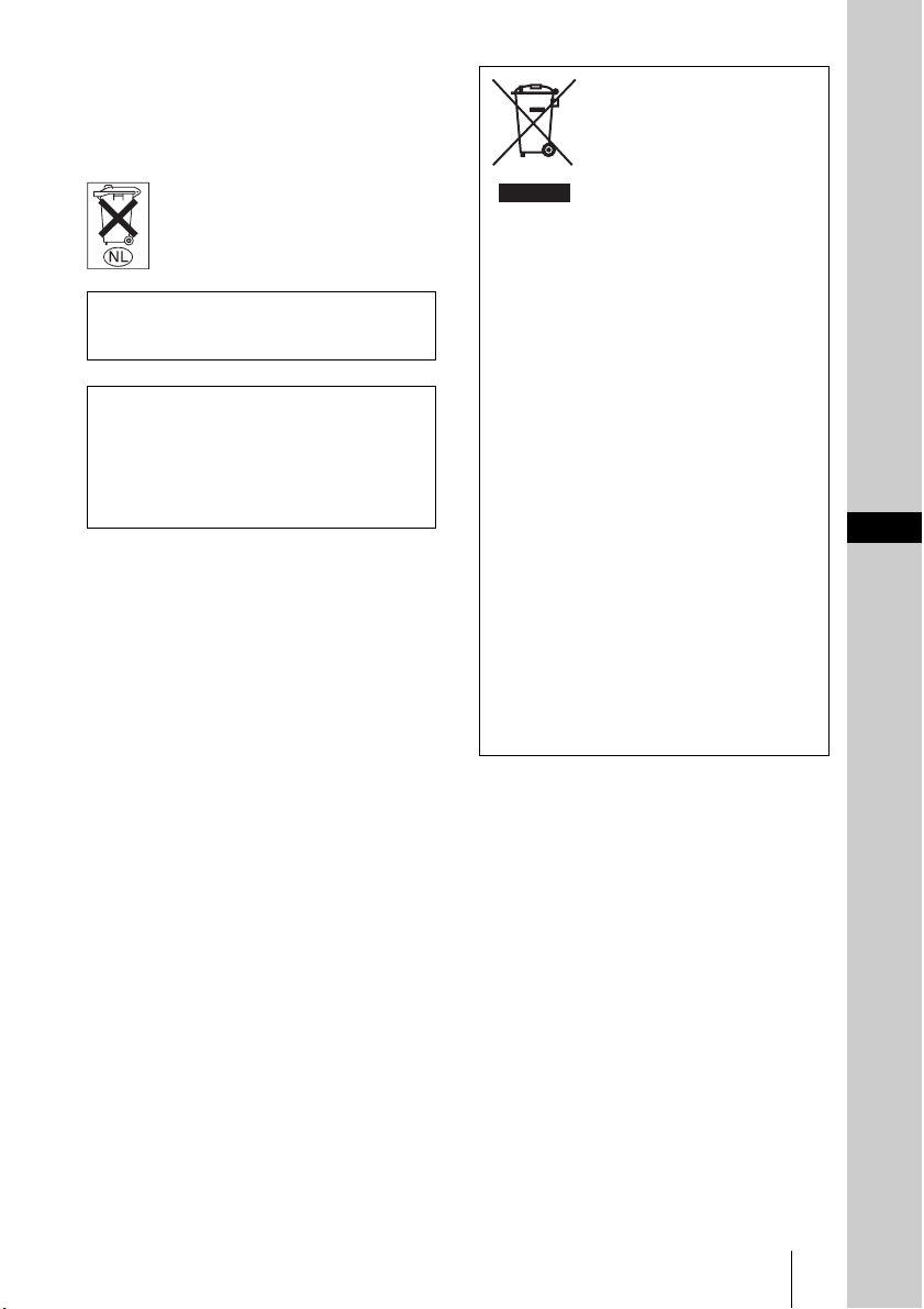
Disposal of Old Electrical &
Electronic Equipment (Applicable
in the European Union and other
European countries with separate
collection systems)
This symbol on the product or on its
packaging indicates that this product
shall not be treated as household waste.
Instead it shall be handed over to the
applicable collection point for the
recycling of electrical and electronic
equipment. By ensuring this product is
disposed of correctly, you will help
prevent potential negative consequences
for the environment and human health,
which could otherwise be caused by
inappropriate waste handling of this
product. The recycling of materials will
help to conserve natural resources. For
more detailed information about
recycling of this product, please contact
your local Civic Office, your household
waste disposal service or the shop where
you purchased the product.
GB
GB
3
Page 4

GB
4
Page 5

Table of Contents
Precautions .........................................7
Location of Controls
Front/Right Side .................................8
Right Side ...........................................9
Rear/Bottom .....................................10
Remote Control ................................11
Connections and
Preparations
Unpacking ........................................12
Step 1: Installing the Projector .........13
Before Setting Up the
Projector ..........................13
Installing the Projector and a
Screen ..............................15
Step 2: Connecting the Projector .....18
Connecting to a DVD Player/
Recorder or Digital
Tuner ...............................18
Connecting to Video
Equipment .......................20
Connecting to a Computer ..........21
Step 3: Adjusting the Picture Size and
Position .............................................22
Step 4: Selecting the Menu
Language ..........................................27
Selecting the Wide Screen Mode .... 33
Selecting the Picture Viewing
Mode ............................................... 36
Adjusting the Picture Quality .......... 37
Adjusting the Picture Using Real Color
Processing ........................................ 39
Using the Menus
Operation through the Menus .......... 41
Picture Menu ................................... 44
Signal Menu ..................................... 47
Function menu ................................. 50
Installation Menu ............................. 51
Setup Menu ...................................... 53
Information Menu ............................ 55
About the Preset Memory No. ... 55
Operating the Projector
from a Computer
Accessing the Projector from a
Computer ......................................... 56
Checking the Status of the
Projector .......................................... 56
Controlling the Projector from a
Computer ......................................... 57
Setting up the Projector ................... 57
Projecting
Projecting the Picture on the
Screen ...............................................29
Turning Off the Power ...............32
Others
Troubleshooting ............................... 59
Warning Indicators .................... 60
Table of Contents
5
GB
Page 6

Message Lists .............................61
Replacing the Lamp ......................... 63
Cleaning the Air Filter .....................66
Replacing the Air Filter ................... 67
Specifications ...................................69
Preset Signals .............................71
Input Signals and Adjustable/
Setting Items ................... 74
Ceiling Installation ........................... 76
When Using the PSS-H10 Projector
Suspension Support .........77
When Using the PSS-610 Projector
Suspension Support .........80
Making Fine Adjustments to the
Horizontal Picture Position .............. 83
Index ...............................................86
GB
6
Table of Contents
Page 7

Precautions
On safety
• Check that the operating voltage of your
unit is identical with the voltage of your
local power supply.
• Should any liquid or solid object fall into
the cabinet, unplug the unit and have it
checked by qualified personnel before
operating it further.
• Unplug the unit from the wall outlet if it is
not to be used for several days.
• To disconnect the cord, pull it out by the
plug. Never pull the cord itself.
• The wall outlet should be near the unit and
easily accessible.
• The unit is not disconnected to the AC
power source (mains) as long as it is
connected to the wall outlet, even if the
unit itself has been turned off.
• Do not look into the lens while the lamp is
on.
• Do not place your hand or objects near the
ventilation holes. The air coming out is
hot.
On preventing internal heat buildup
After you turn off the power with the I/1
(on/standby) switch, do not disconnect the
unit from the wall outlet while the cooling
fan is still running.
Caution
The projector is equipped with ventilation
holes (intake) and ventilation holes
(exhaust). Do not block or place anything
near these holes, or internal heat build-up
may occur, causing picture degradation or
damage to the projector.
On repacking
Save the original shipping carton and
packing material; they will come in handy if
you ever have to ship your unit. For
maximum protection, repack your unit as it
was originally packed at the factory.
Precautions
GB
7
Page 8
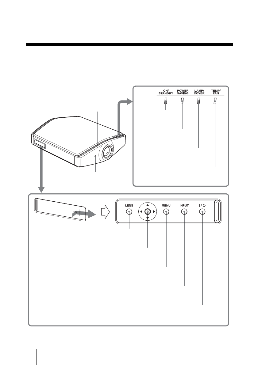
Location of Controls
Front/Right Side
You can use the buttons on the control panel with the same names as those on
the remote control to operate the projector.
Ventilation holes
(intake) (1 page 14)
ON/STANDBY
indicator (1 page 23)
POWER SAVING
indicator (1 page 50)
LAMP/COVE R indicator
(1 page 60)
Remote control
detector (1 page 22)
Open the cover by pushing it.
TEMP/FAN Indicator
(1 page 60)
LENS button
(1 page 23)
M/m/</, (arrow)/
ENTER button
(1 page 41)
MENU button (1 page 41)
INPUT button (1 page 30)
?/1 (on/standby) switch (1 page 23)
GB
8
Front/Right Side
Page 9
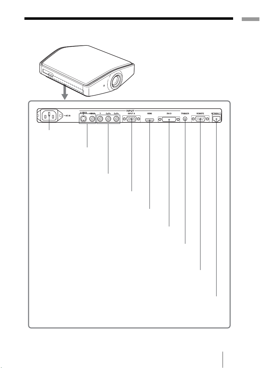
Right Side
- AC IN socket
S VIDEO INPUT connector
(mini DIN 4-pin)/
VIDEO INPUT connector
(phono type) (1 page 20)
Y/CB/PB/CR/PR (phono type) (1 page 18)
INPUT A connector (1 page 21)
Location of Controls
HDMI connector (1 page 19)
DVI-D connector (1 page 21)
TRIGGER jack (mini jack)
Outputs a 12 V signal
when the power is on.
REMOTE connector
Connects to a computer,
etc. for remote control
NETWORK connector
Connects to a computer,
etc. for remote control
Right Side
GB
9
Page 10
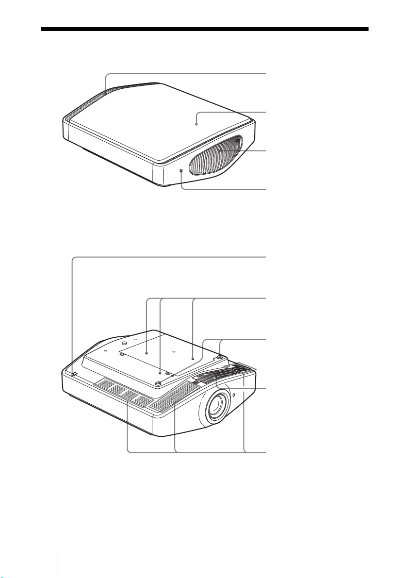
Rear/Bottom
Ventilation holes (intake)
(1 page 14)
Top cover
(1 page 63)
Ventilation holes
(exhaust) (1 page 14)
Remote control detector
(1 page 22)
Cover release lever
(1 page 63)
Projector suspension
support attachment holes
(1 page 76)
GB
10
Adjusters
(1 page 26)
Filter holder
(1 page 66)
Ventilation holes (intake)
(1 page 14)
Rear/Bottom
Page 11
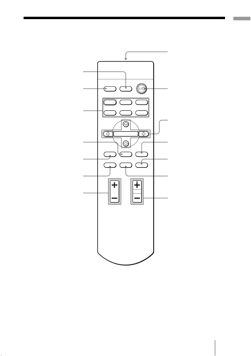
Remote Control
INPUT button
(1 page 30)
Location of Controls
Infrared transmitter
Illuminates the buttons on
LIGHT button
the remote control.
PICTURE MODE
buttons (1 page 36)
ADJ PIC button
(1 page 37)
LENS button
(1 page 22)
WIDE MODE button
(1 page 33)
BRIGHT +/– button
(1 page 38)
INPUTLIGHT
STANDARD
USER 2
ENTER
ADJ PIC
RCP
CINEMA
USER 3USER 1
MENULENS
RESET
DYNAMIC
PICTURE MODE
WIDE MODE
REAL COLOR PROCESSING
BRIGHT CONTRAST
?/1 (on/standby) switch
(1 page 23)
M/m/</, (arrow)/
ENTER buttons
(1 page 41)
MENU button
(1 page 41)
RESET button
(1 page 43)
RCP button
(1 page 39)
CONTRAST +/– button
(1 page 38)
Remote Control
11
GB
Page 12
Connections and Preparations
This section describes how to install the projector and screen, how to connect
the equipment from which you want to project the picture, etc.
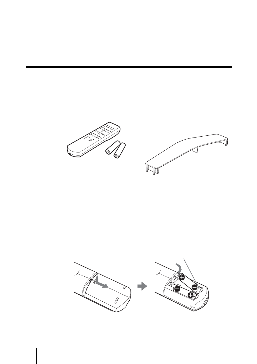
Unpacking
Check the carton to make sure it contains the following items:
• Remote control (1) and
Size AA (R6) batteries (2)
• AC power cord (1)
• ImageDirector2 CD-ROM (1)
• Plug holder
Attach the plug holder to avoid
unplugging the AC power cord
accidentally.
•Air filter cover (1)
This air filter cover is used only when
the projector is installed on a ceiling.
(1 page 76)
• Lens cap (1)
When you have purchased the projector,
the lens cap was fitted onto the lens.
Remove this lens cap when you use the
projector.
• Operating Instructions (this manual) (1)
Inserting the batteries into the remote control
Insert the batteries E side first as shown in the illustration.
Inserting them forcibly or with the polarities reversed may cause
a short circuit and may generate heat.
GB
12
Unpacking
Page 13
Step 1: Installing the Projector
Before Setting Up the
Projector
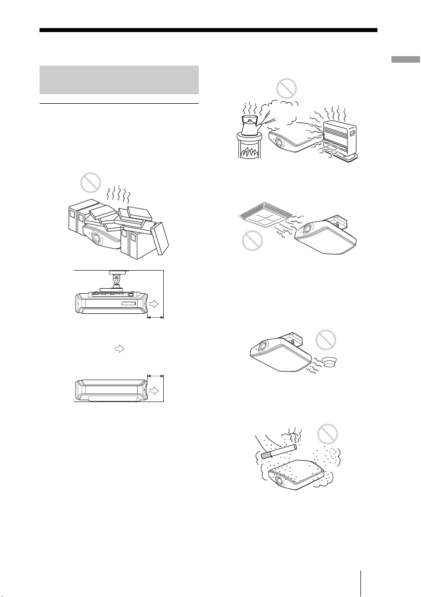
Unsuitable installation
Do not place the projector in the following
situations, which may cause malfunction
or damage to the projector.
Poorly ventilated location
20 cm
Exhaust
:
20 cm
Hot and humid
Locations subject to direct cool or
warm air from an air-conditioner
Installing the projector in such a location
may cause a malfunction of the unit due to
moisture condensation or rise in
temperature.
Near a heat or smoke sensor
Connections and Preparations
To maintain the performance and reliability
of the projector, do not put any object within
20 cm (7
7
/8 inches) from the rear panel.
The temperature of the wall may be affected
if you do so.
Malfunction of the sensor may occur.
Very dusty and extremely smoky
locations
Step 1: Installing the Projector
13
GB
Page 14
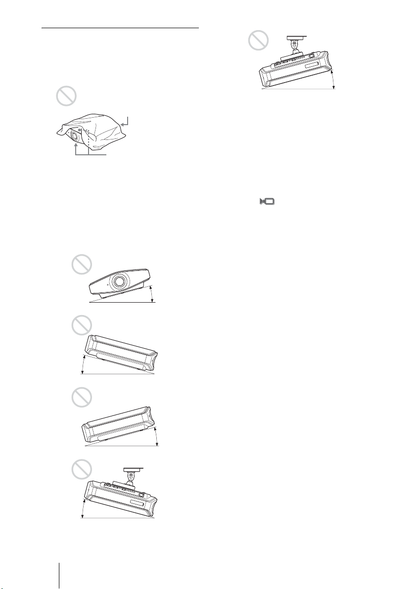
Improper use
Do not do any of the following while using
the projector.
Blocking the ventilation holes.
Ventilation holes
(exhaust)
Ventilation holes
(intake)
Tip
For details on the location of the ventilation
holes (intake or exhaust), see “Location of
Controls” on pages 8 to 10.
Tilting front/rear and left/right
15º or more
15º or more
Avoid using the projector tilted at an angle
of more than 15 degrees.
Do not install the projector anywhere other
than on a level surface or on the ceiling.
Improper installation of the projector may
cause a malfunction.
When installing the unit at altitudes
When using the projector at an altitude of 1,500
m or higher, set “High Altitude Mode” in the
Installation menu to “On.” (1 page 52)
Failing to set this mode when using the
projector at high altitudes could have adverse
effects, such as reducing the reliability of
certain components.
15º or more
15º or more
GB
14
15º or more
Step 1: Installing the Projector
Page 15
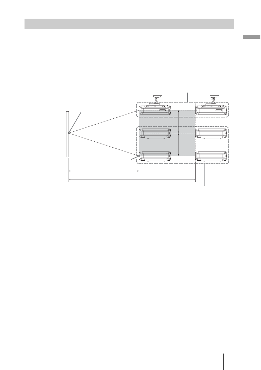
Installing the Projector and a Screen
The installation distance between the projector and a screen varies depending
on the size of the screen.
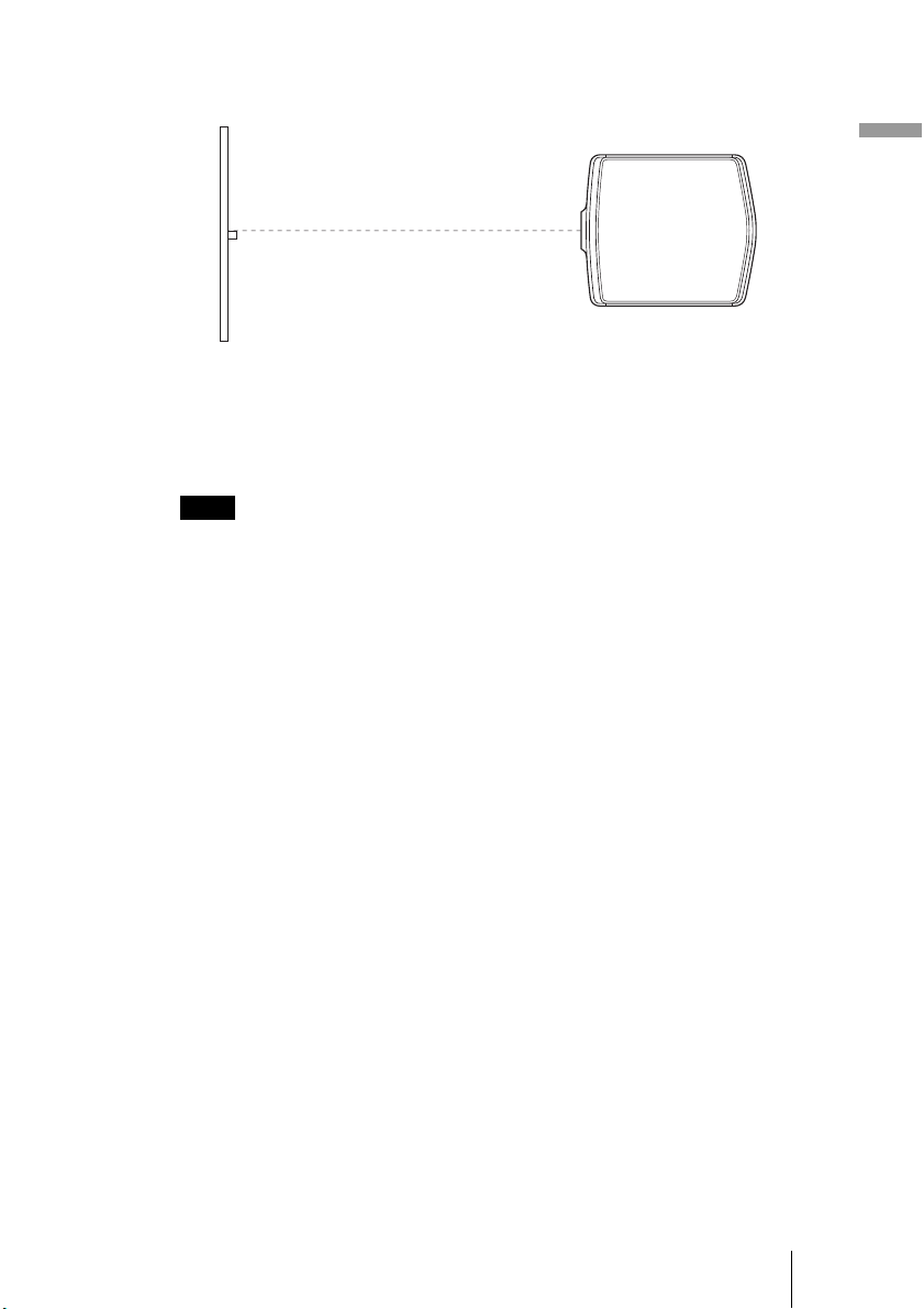
1 Determine the installation position of the projector and screen.
You can obtain a good quality picture if you position the projector with the
center of the lens within the areas indicated in the gray areas in the
illustration. Use the values a, b and c in the table on page 16 as a guide.
Ceiling installation
Center of the screen
c
c
Center of projector’s
lens
a
b
Floor installation
a: Minimum projection distance between the screen and the center of the
projector’s lens
b: Maximum projection distance between the screen and the center of the
projector’s lens
c: Vertical distance between the center of the screen and the center of the
projector’s lens when using the maximum upper vertical lens shift
feature.
Connections and Preparations
For details on the lens shift feature, see “Step 3: Adjusting the Picture Size
and Position.” (1 page 22)
Step 1: Installing the Projector
15
GB
Page 16
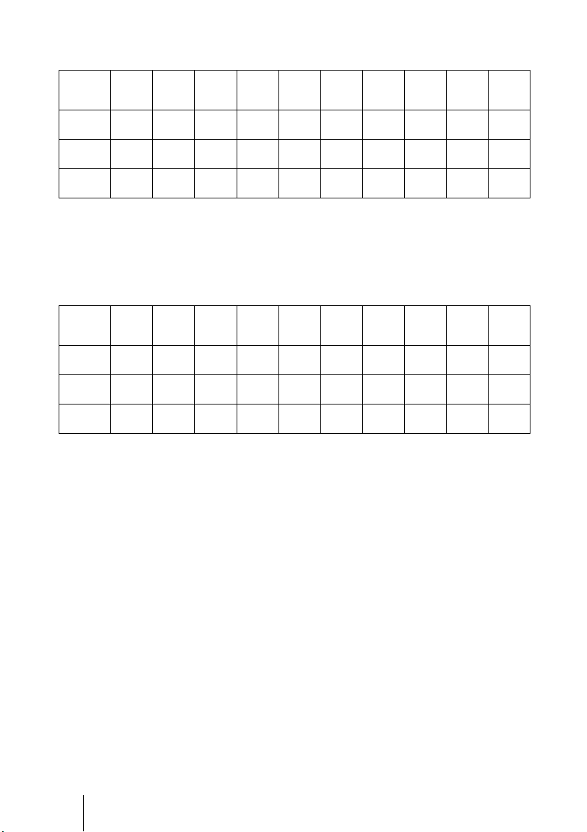
Screen
size
(inches)
a
(minimum)
b
(maximum)
c
Screen
size
(inches)
a
(minimum)
b
(maximum)
c
When using the 16:9 aspect ratio screen
Unit: mm (inches)
40 60 80 100 120 150 180 200 250 300
1212
(47
2105
(82
324
(12
1842
3
/4)
(72 1/2)
3181
7
/8)
(125 1/4)
485
3
/4)
(19 1/8)
To calculate the installation measurements (SS: Screen Size)
a (minimum) = 31.5 (1
b (maximum) = 53.8 (2
c = 8.0876 (
2472
(97 3/8)
4257
(167 5/8)
647
(25 1/2)
11
/32) × SS
3102
3732
(122 1/8)
(146 7/8)
5333
6409
(210)
(252 3/8)
809
971
(31 7/8)
(38 1/4)
1
/4) × SS – 48.2 (1 15/16)
1
/8) × SS – 46.9 (1 7/8)
4677
(184 1/8)
8023
(315 7/8)
1213
(47 3/4)
5622
(221 3/8)
9637
(379 3/8)
1456
(57 3/8)
6252
(246 1/8)
10713
(421 3/4)
1618
(63 5/8)
7827
(308 1/8)
13403
(527 5/8)
2022
(79 5/8)
9402
(370 1/8)
16093
(633 5/8)
2426
(95 1/2)
When using the 4:3 aspect ratio screen (projecting a 4:3 picture)
Unit: mm (inches)
40 60 80 100 120 150 180 200 250 300
1494
(58
2587
(101
396
(15
2265
3
/4)
(89 1/8)
3904
7
/8)
(153 5/8)
594
5
/8)
(23 3/8)
To calculate the installation measurements (SS: Screen Size)
a (minimum) = 38.551 (1
b (maximum) = 65.842 (2
c = 9.8979 (
3036
(119 1/2)
5220
(205 1/2)
792
(31 1/8)
13
/32) × SS
3807
4578
(149 7/8)
(180 1/4)
6537
7854
(257 3/8)
(309 1/4)
990
1188
(39)
(46 3/4)
9
/16) × SS – 48.2 (1 15/16)
5
/8) × SS – 46.9 (1 7/8)
5734
(225 3/4)
9829
(387)
1485
(58 1/2)
6891
(271 1/4)
11805
(464 3/4)
1782
(70 1/8)
7662
(301 5/8)
13122
(516 5/8)
1980
(77 7/8)
9590
(377 1/2)
16414
(646 1/4)
2474
(97 3/8)
11517
(453 3/8)
19706
(775 7/8)
2969
(116 7/8)
GB
16
Step 1: Installing the Projector
Page 17
2 Position the projector so that the lens is parallel to the screen.
Top view
Screen
3 Project an image on the screen and adjust the picture so that it
fits the screen. (1 page 22)
To project an image, connect video equipment to the projector. (1 page
18)
Note
When using a screen with an uneven surface, stripes pattern may rarely appear on the
screen depending on the distance between the screen and the projector or the zooming
magnifications. This is not a malfunction of the projector.
For installation of the projector on a ceiling, see “Ceiling Installation.” (1
page 76)
Connections and Preparations
Step 1: Installing the Projector
17
GB
Page 18
Step 2: Connecting the Projector
When making connections, be sure to do the following:
• Turn off all equipment before making any connections.
• Use the proper cables for each connection.
• Insert the cable plugs properly; plugs that are not fully inserted often
generate noise. When pulling out a cable, be sure to pull it out from the plug,
not the cable itself.
• Refer to the operating instructions of the connected equipment.
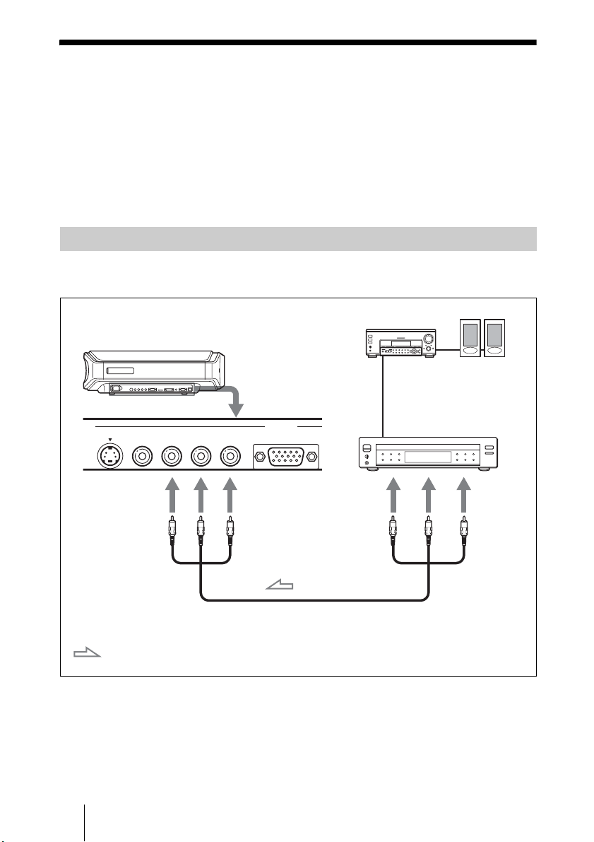
Connecting to a DVD Player/Recorder or Digital Tuner
To connect to a DVD player/recorder or digital tuner equipped with
component video connectors
AV amplifier
Right side of the projector
DVD player/recorder, HDD
recorder, digital tuner, etc.,
with component video
connectors
Y
PB/
CB
S VIDEO
VIDEO
Y
: Video signal flow
YCB/PBCR/P
CB/
B
P
Component video cable (not supplied)
R
CR/PR
INPUT
INPUT A
Tip
To connect the projector to a DVD player/recorder, HDD recorder, digital tuner, etc.
which is not equipped with component video connectors, it is recommended to use the
S video cable to connect to the S-video output of the DVD player/recorder, HDD
recorder, digital tuner, etc. If the connected equipment is not equipped with the S-video
output connector, use the video cable to connect to the video output jack on the
equipment.
Speakers
PR/
CR
GB
18
Step 2: Connecting the Projector
Page 19
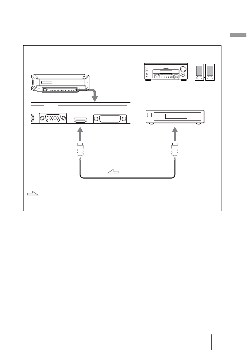
To connect to a DVD player/recorder equipped with HDMI
R
output
You can enjoy better picture quality by connecting a DVD player/recorder
equipped with HDMI output to the HDMI input of the projector.
Connections and Preparations
Right side of the projector
INPUT
R
INPUT A HDMI DVI-D T
: Video signal flow
HDMI cable (not supplied)
AV amplifier
DVD player/recorder,
etc., with the HDMI
output
Speakers
to HDMI output
............................................................................................................................................................
HDMI, HDMI logo and High-Definition Multimedia Interface are trademarks or registered
trademarks of HDMI Licensing LLC. This HDMI connector conforms to Ver. 1.1.
Step 2: Connecting the Projector
19
GB
Page 20
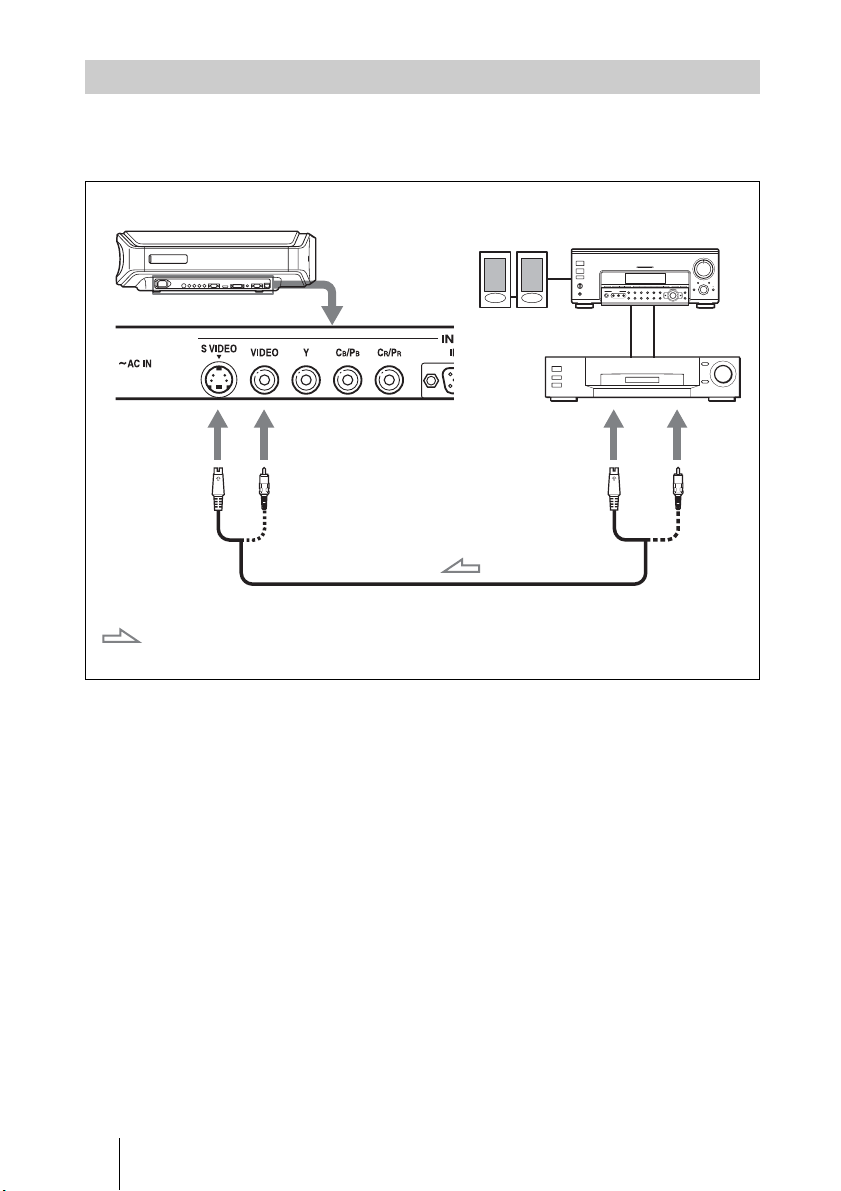
Connecting to Video Equipment
You can connect a DVD player/recorder which is not equipped with
component video connectors, hard disk video recorder, VCR or laser disk
player. See also the instruction manual of each equipment.
Right side of the projector
S video or video cable (not supplied)
: Video signal flow
Speakers
Video equipment
to S video or
video output
AV amplifier
GB
Tip
If you do not know to which connector you should connect the cable, S VIDEO INPUT
(S video input connector) or VIDEO INPUT (video input connector), connect it to S
VIDEO to enjoy better picture quality.
If the equipment to be connected has no S video connector, connect the cable to the
video output.
20
Step 2: Connecting the Projector
Page 21
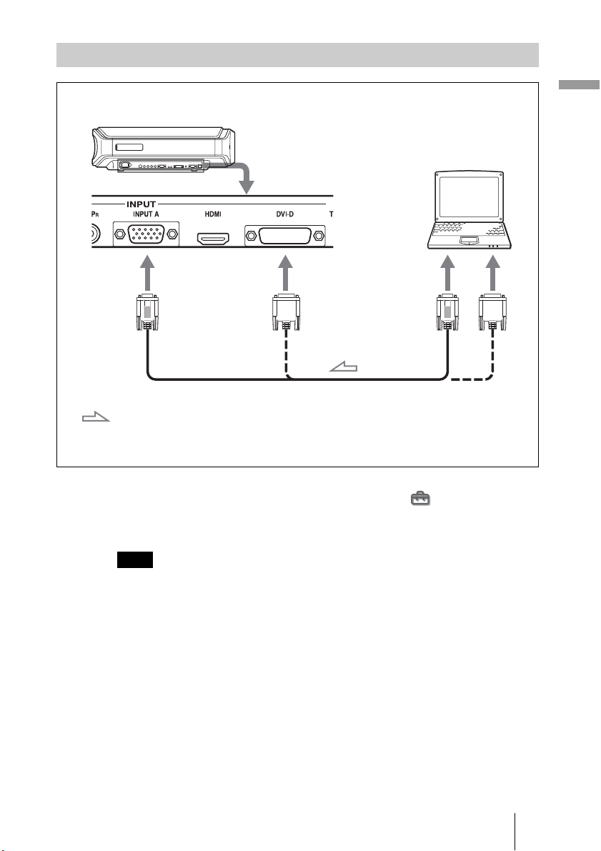
Connecting to a Computer
Right side of the projector
Computer
to monitor output
HD D-sub 15-pin cable (not supplied),
: Video signal flow
or DVI - DVI cable (not supplied)
Tip
Set “Input-A Signal Sel.” or “DVI Signal Sel.” in the Setup menu to “Auto” or
“Computer.” If the input signal does not appear properly, set it to “Computer.” (1 page
53)
Connections and Preparations
Note
If you set your computer, such as a notebook type, to output the signal to both your
computer’s display and an external monitor, the picture of the external monitor may not
appear properly. Set your computer to output the signal to only the external monitor.
For details, refer to the computer’s operating instructions supplied with your computer.
Step 2: Connecting the Projector
21
GB
Page 22
Step 3: Adjusting the Picture Size and
Position
Project an image on the screen and then adjust the picture position.
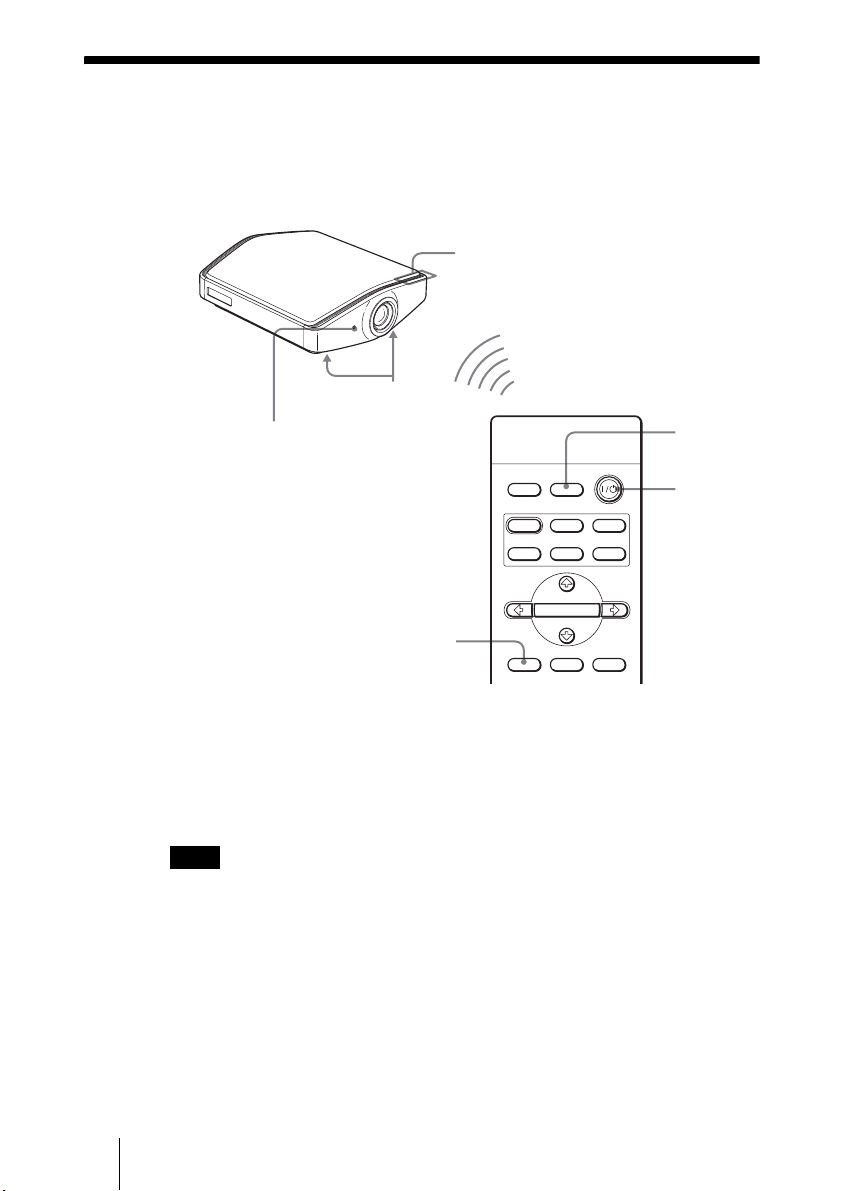
ON/STANDBY indicator
Adjusters
Remote control detector
5,6,7
DYNA MIC
INPUTLIGHT
STANDARD
PICTURE MODE
USER 2
ENTER
ADJ PIC
CINEMA
USER 3USER 1
MENULENS
4
2
Tip
?/1 (on/standby), INPUT, LENS, MENU, and M/m/</,/ENTER (joystick)
The
buttons on the side panel of the projector function the same as those on the remote
control.
Note
Depending on the installation location of the projector, you may not control it with the
remote control. In this case, point the remote control to the screen instead of the
projector.
GB
22
Step 3: Adjusting the Picture Size and Position
Page 23
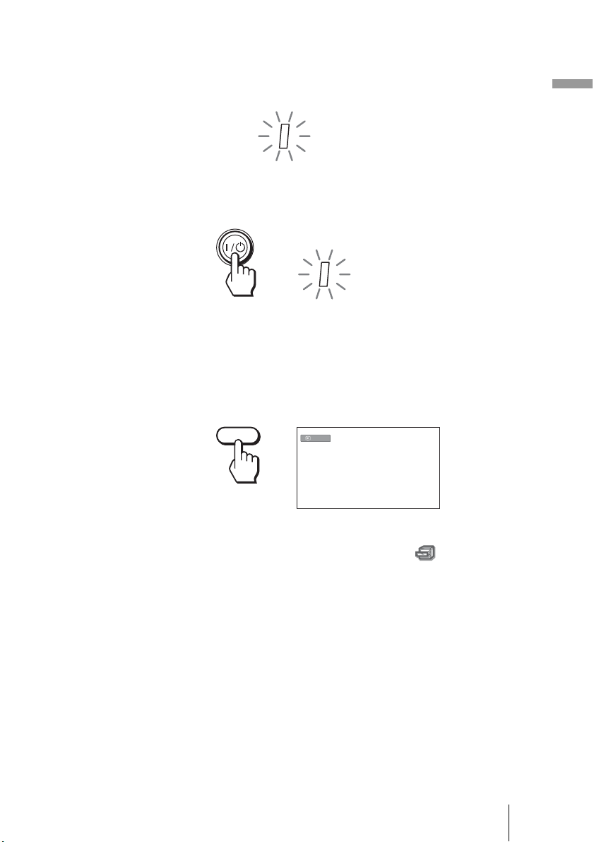
1 Plug the AC power cord into a wall outlet.
The ON/STANDBY indicator lights in red and the projector goes into
standby mode.
ON/
STANDBY
Lights in red.
2 Press the ?/1 (on/standby) switch to turn on the projector.
The ON/STANDBY indicator flashes in green, and then lights in green.
Connections and Preparations
ON/
STANDBY
Flashes in green for a few
seconds, and then lights in
green.
3 Turn on the equipment connected to the projector.
Refer to the operating instructions of the connected equipment.
4 Press INPUT to project the picture on the screen.
Each time you press the button, the input indication and equipment to be
projected change. (1 page 30)
INPUT
Tip
When “Auto Input Search” is set to “On” in the Function menu, the channel
of the signal input is automatically displayed by pressing INPUT. (1 page 50)
Video
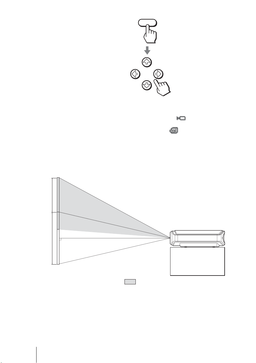
5 Adjust the vertical picture position.
Press the LENS button repeatedly until the Lens Shift adjustment window
(test pattern) appears. Then select the proper vertical position by pressing
the M/m/</, buttons.
To move the position upward, press
To move the position downward, press
M or ,.
m or <.
Step 3: Adjusting the Picture Size and Position
23
GB
Page 24
0.65V
LENS
Tip
When “Lens Control” is set to “Off” on the Installation
menu, you cannot
adjust the vertical picture position. (1 page 51)
When “Test Pattern” is set to “Off” on the Function menu, the test pattern is
not displayed. (1 page 50)
The picture moves up by a maximum of 0.65 of the screen size from the
center of the lens.
Side view
GB
1V
Tip
You can also adjust the horizontal position of the lens. For detailed information, see
“Making Fine Adjustments to the Horizontal Picture Position” on page 83.
24
Step 3: Adjusting the Picture Size and Position
: Picture position when the picture is
moved upward at the maximum
Page 25
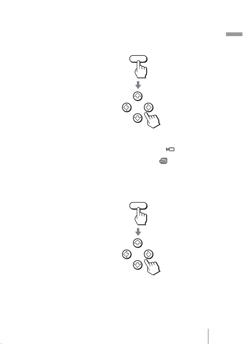
6 Adjust the picture size.
Press the LENS button repeatedly until the Lens Zoom adjustment window
(test pattern) appears. Then adjust the size of the picture by pressing the M/
m/</, buttons.
To make the picture larger, press
To make the picture smaller, press
Tip
When “Lens Control” is set to “Off” on the Installation menu, you cannot
adjust the picture size and the focus. (1 page 51)
When “Test Pattern” is set to “Off” on the Function menu, the test pattern is
not displayed. (1 page 50)
M or ,.
m or <.
LENS
7 Adjust the focus.
Press the LENS button repeatedly until the Lens Focus adjustment window
(test pattern) appears. Then adjust the focus of the picture by pressing the
M/m/</, buttons.
LENS
Connections and Preparations
Step 3: Adjusting the Picture Size and Position
25
GB
Page 26
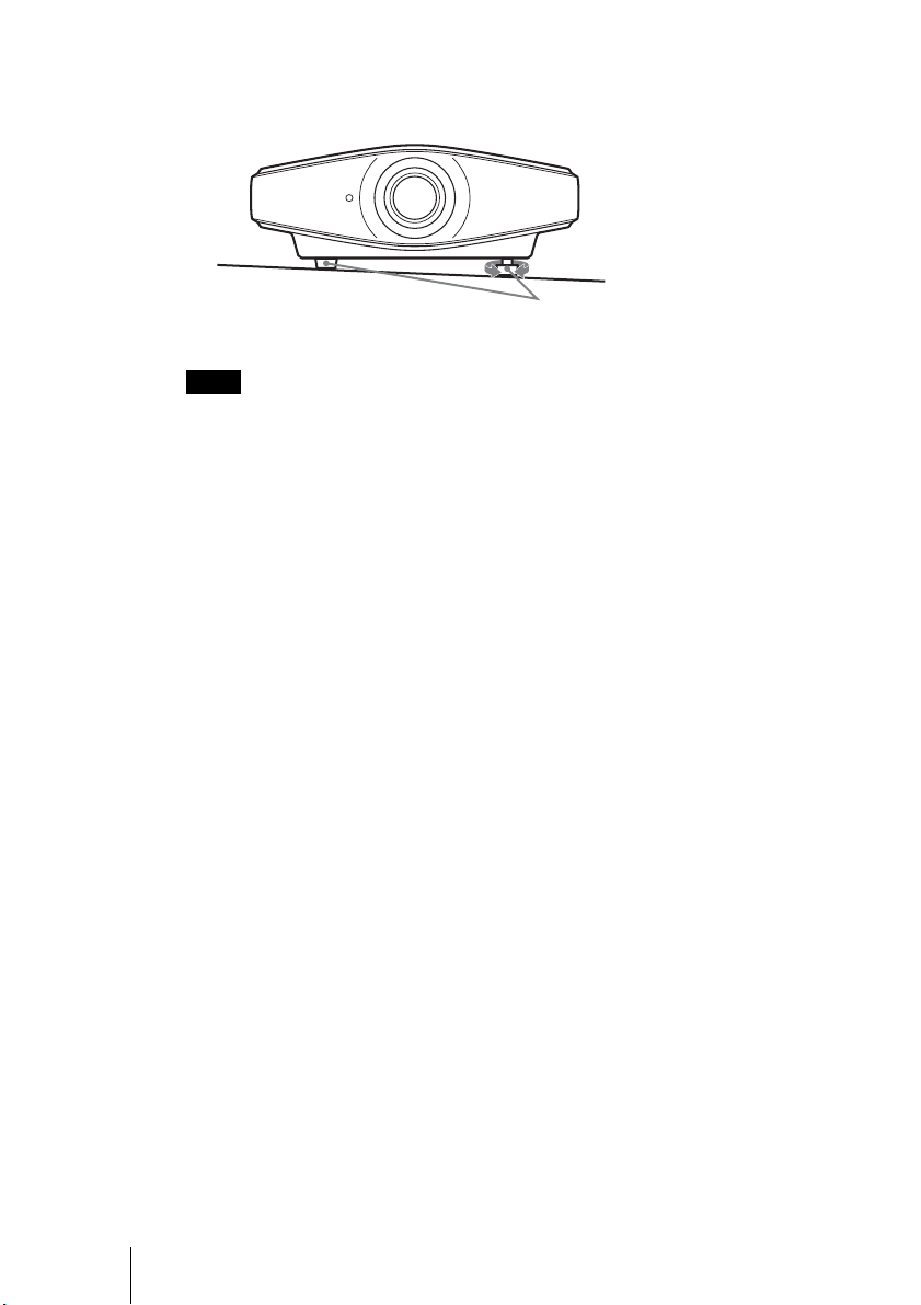
To adjust the tilt of the installation surface
If the projector is installed on an uneven surface, use the adjusters to keep the
projector level.
Turn to adjust.
Adjusters
Note
Be careful not to catch your finger when turning the adjusters.
GB
26
Step 3: Adjusting the Picture Size and Position
Page 27
Step 4: Selecting the Menu Language
You can select one of fifteen languages for displaying the menu and other onscreen displays. The factory default setting is English.
INPUTLIGHT
STANDARD
PICTURE MODE
USER 2
ENTER
ADJ PIC
RCP
CINEMA
USER 3USER 1
MENULENS
RESET
DYNA MIC
WIDE MODE
REAL COLOR PROCESSING
BRIGHT CONTRAST
Tip
You can operate the menu using the M/m/</, (arrow)/ENTER buttons on the side
panel of the projector instead of the M/m/</,/ENTER buttons on the remote control.
2
4,5,6
3
3
1 Plug the AC power cord into a wall outlet.
The ON/STANDBY indicator lights in red and the projector goes into
standby mode.
Connections and Preparations
2 Press the ?/1 (on/standby) switch to turn on the projector.
The ON/STANDBY indicator flashes in green, and then lights in green.
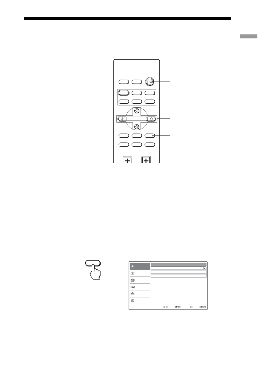
3 Press MENU.
The menu appears.
MENU
Picture Mode :
Picture
Adjust Picture
RCP :
Signal
Color Space :
Function
Installation
Setup
Information
Sel : Set : Back : Exit :
Step 4: Selecting the Menu Language
Cinema
Off
Normal
27
GB
Page 28

4 Press M or m to select the Setup menu, and press , or
ENTER.
The setting items of the selected menu appears.
Status : On
Picture
Language : English
Input-A Signal Sel. : Computer
Signal
DVI Signal Sel. : Video GBR
Color System : Auto
Function
Installation
Setup
or
ENTER
Information
Sel: Set: Back: Exit:
5 Press M or m to select “Language,” and press , or ENTER.
Status : On
Picture
Language : English
Input-A Signal Sel. Center
Signal
DVI Signal Sel. : Video GBR
Color System : Auto
Function
Installation
Setup
or
or
ENTER
Information
Sel : Set : Exit :
GB
6 Press M/m/</, to select a language, and press ENTER.
The menu changes to the selected language.
To clear the menu
Press MENU.
28
Step 4: Selecting the Menu Language
Page 29
Projecting
This section describes how to operate the projector to view the picture from the
equipment connected to the projector. It also describes how to adjust the
quality of the picture to suit your taste.
Projecting the Picture on the Screen
Remote control detector
ON/STANDBY indicator
Projecting
4
INPUTLIGHT
STANDARD
PICTURE MODE
USER 2
ENTER
ADJ PIC
CINEMA
USER 3USER 1
MENULENS
DYNA MIC
5,6
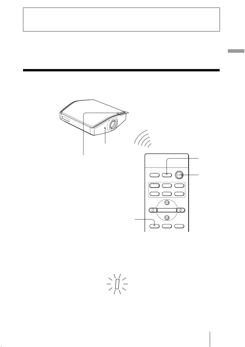
1 Plug the AC power cord into a wall outlet.
The ON/STANDBY indicator lights in red and the projector goes into
standby mode.
ON/
STANDBY
Lights in red.
Projecting the Picture on the Screen
2
GB
29
Page 30
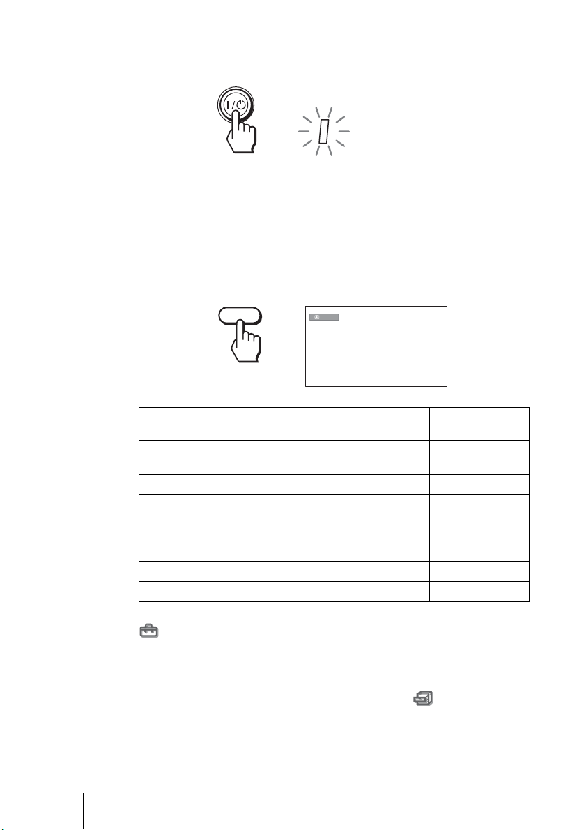
2 Press the ?/1 (on/standby) switch to turn on the projector.
The ON/STANDBY indicator flashes in green, and then lights in green.
ON/
STANDBY
Flashes in green for a few
seconds, and then lights in
green.
3 Turn on the equipment connected to the projector.
Refer to the operating instructions of the connected equipment.
4 Press INPUT repeatedly to select the input you want to project
on the screen.
Display the indication of the input you want.
Example: To view the picture from the video equipment connected to the
VIDEO INPUT connector.
INPUT
To view the picture from Press INPUT to
Video equipment connected to the VIDEO INPUT
connector
Video equipment connected to S VIDEO INPUT connector S-Video
Component equipment connected to Y/C
projector
RGB/component equipment connected to the INPUT A
connector
Video equipment connected to the DVI-D connector DVI*
Equipment connected to the HDMI connector HDMI
Video
B/PB/CR/PR on the
display
Video
Component
Input-A*
GB
*Set the “Input-A Signal Sel.” setting and “DVI Signal Sel.” setting in the Setup
menu according to the signal input. When you set it to “Auto,” and cannot
display the picture properly, select an appropriate signal according to the input
signal. (1 page 53)
Tip
When “Auto Input Search” is set to “On” in the Function menu, the channel
of the input signal is automatically displayed when you press INPUT.
30
Projecting the Picture on the Screen
Page 31

5 Adjust the picture size.
Press the LENS button repeatedly until the Lens Zoom adjustment window
(test pattern) appears. Then adjust the size of the picture by using the M/m/
</, buttons.
To make the picture larger, press M or ,.
To make the picture smaller, press m or <.
LENS
Tip
When “Lens Control” is set to “Off” on the Installation menu, you cannot
adjust the picture size and the focus of the picture. (1 page 51)
When “Test Pattern” is set to “Off” on the Function menu, the test pattern is
not displayed. (1 page 50)
6 Adjust the focus.
Press the LENS button repeatedly until the Lens Focus adjustment window
(test pattern) appears. Then adjust the focus of the picture by using the M/
m/</, buttons.
LENS
Projecting
To adjust the vertical position
You can also adjust the vertical position using the LENS button. (1 page 23)
Projecting the Picture on the Screen
31
GB
Page 32

Turning Off the Power
1 Press the ?/1 (on/standby) switch.
A message “POWER OFF?” appears on the screen.
2 Press the ?/1 switch again.
The ON/STANDBY indicator flashes in green and the fan continues to run
to reduce the internal heat. First, the ON/STANDBY indicator flashes
quickly, during which you will not be able to light up the ON/STANDBY
indicator with the
3 Unplug the AC power cord from the wall outlet after the fan
stops running and the ON/STANDBY indicator lights in red.
?/1 switch.
You can turn off the projector by holding the
one second, instead of performing the above steps.
?/1 (on/standby) switch for about
GB
32
Projecting the Picture on the Screen
Page 33

Selecting the Wide Screen Mode
You can enjoy various wide screen modes according to the video signal
received. You can also select it using the menu. (1 page 47)
INPUTLIGHT
STANDARD
PICTURE MODE
USER 2
ENTER
ADJ PIC
RCP
CINEMA
USER 3USER 1
MENULENS
RESET
DYNA MIC
WIDE MODE button
WIDE MODE
REAL COLOR PROCESSING
BRIGHT CONTRAST
Press WIDE MODE.
Each time you press the button, you can select the “Wide Mode” setting.
Full
A picture squeezed to 4:3 is displayed with the correct aspect ratio. A 4:3
picture is enlarged horizontally to fit the 16:9 screen.
Projecting
Tip
Squeezed: An original 16:9 aspect ratio picture is recorded horizontally compressed to
a 4:3 picture.
Selecting the Wide Screen Mode
33
GB
Page 34

Normal
A picture with normal 4:3 aspect ratio is displayed in the center of the screen
to fill the vertical screen size.
Wide Zoom
A 4:3 aspect ratio picture is enlarged and the upper and lower portions of the
picture are compressed to fit the 16:9 screen. Use this mode to view news,
variety shows, etc.
Zoom
A normal 4:3 aspect ratio picture is enlarged vertically and horizontally in the
same ratio to fill the screen. Use this mode to view a letterbox picture.
GB
Subtitle
The subtitle area is compressed and displayed in the lower part of the screen.
Use this mode to view a movie with subtitles.
Notes
• You can adjust the vertical position of the picture with “V Position” in the Signal
menu only when “Zoom” or “Subtitle” is selected (1 page 48).
• You can adjust the position of the subtitles with “Title Area” in the Signal menu
only when “Subtitle” is selected (1 page 48).
34
Selecting the Wide Screen Mode
Good-bye
Page 35

Notes on selecting the wide screen mode
• Select the wide screen mode taking into account that changing the aspect
ratio of the original picture will provide a different look from that of the
original image.
• Note that if the projector is used for profit or for public viewing, modifying
the original picture by switching to the wide mode may constitute an
infringement of the rights of authors or producers, which are legally
protected.
Projecting
Selecting the Wide Screen Mode
35
GB
Page 36

Selecting the Picture Viewing Mode
You can select the picture viewing mode that best suits the type of program or
room conditions.
INPUTLIGHT
STANDARD
PICTURE MODE
USER 2
ENTER
ADJ PIC
RCP
CINEMA
USER 3USER 1
MENULENS
RESET
PICTURE MODE buttons
DYNAMIC
STANDARD
CINEMA
USER 1, USER 2 and USER 3
DYNA MIC
WIDE MODE
REAL COLOR PROCESSING
BRIGHT CONTRAST
Press one of the PICTURE MODE buttons (DYNAMIC,
STANDARD, CINEMA and USER 1, USER 2 and USER 3).
DYNAMIC
Enhances picture contrast and sharpness.
GB
STANDARD
Recommended for normal viewing conditions. Select this if you encounter
roughness when viewing the picture with “DYNAMIC.”
CINEMA
Recommended when viewing a movie in the dark place.
USER 1, USER 2 and USER 3
You can adjust the quality of the picture to suit your taste and store the settings
into the selected memory of the projector. Press one of the USER 1, USER 2
and USER 3 buttons, then adjust the picture by using the buttons on the remote
control or the menus. (1 pages 37 and 44) The settings are stored, and you
can view the picture with the adjusted picture quality by pressing the button.
36
Selecting the Picture Viewing Mode
Page 37

Adjusting the Picture Quality
You can adjust the picture quality that suits your taste by selecting the
adjustment items with the remote control. The adjusted data can be stored in
each picture mode.
INPUTLIGHT
STANDARD
PICTURE MODE
USER 2
ENTER
CINEMA
USER 3USER 1
DYNA MIC
Projecting
ADJ PIC
MENULENS
RCP
WIDE MODE
REAL COLOR PROCESSING
BRIGHT CONTRAST
RESET
ADJ PIC button
CONTRAST +/– button
BRIGHT +/– button
1 Press ADJ PIC.
Each time you press the button, the following adjustment windows* are
displayed in sequence.
Contrast t Brightness t Color t Hue t Sharpness t NR
rR
Advanced Iris T Color Temp. T Gamma Correction T Black Level Adj.
* Some of the above adjustment windows will not be displayed depending on the
input signal. For details, see “Input Signals and Adjustable/Setting Items.” (1
page 74)
Adjusting the Picture Quality
37
GB
Page 38

Example: To adjust the contrast
Contrast
For details on each adjustment, see “Adjust Picture” in the Picture
menu. (1 page 44)
2 Make the setting or adjustment on an item.
When changing the adjustment level
To increase the value, press ,.
To decrease the value, press <.
When changing the setting
Press M or m to change the setting.
To adjust contrast and brightness
Press CONTRAST +/– on the remote control to adjust the contrast.
Press BRIGHT +/– on the remote control to adjust the brightness.
GB
38
Adjusting the Picture Quality
Page 39

Adjusting the Picture Using Real Color
Processing
The Real Color Processing (RCP) feature allows you to adjust the color and
hue of each target of the projected picture you specify independently. You can
thus obtain a picture more suitable to your taste.
INPUTLIGHT
STANDARD
PICTURE MODE
USER 2
CINEMA
USER 3USER 1
DYNA MIC
Projecting
ENTER
ADJ PIC
MENULENS
RCP
WIDE MODE
REAL COLOR PROCESSING
BRIGHT CONTRAST
RESET
2, 3, 4
1
Tip
Freeze the scene of the video source when you are adjusting the picture using Real Color
Processing.
1 Press RCP on the remote control.
2 Press M or m to select “User 1,” “User 2” or “User 3,” then
,.
press
The RCP (Real Color Processing) window appears.
3 Select the target color you want to adjust.
Repeat steps 1 and 2 described below to specify the target color.
1 Press
M or m to select “Color Select,” then press < or , to select the
color you want to adjust among “Red,” “Yellow,” “Green,” “Cyan,”
“Blue” and “Magenta.”
Only the portions that correspond to the specified color will be colored
and the other portions will be displayed in black and white. The
reference palette in the RCP window also shows the adjustable colors.
Decide the target while you are watching the projected picture, and
watching the reference palette as a guide.
Adjusting the Picture Using Real Color Processing
39
GB
Page 40

Reference palette
2 Press M or m to select “Position” or “Range,” and specify it more
delicate color and color range you want to adjust using
< or ,.
4 Adjust the color of the specified portions.
Press
M or m to select “RCP Color” or “RCP Hue,” then adjust the color or
hue of the portions selected in step 3 to suit your taste using
< or , while
watching the projected picture. The picture is returned to normal color
during adjustment.
5 After the adjustment is complete, press RCP.
The RCP window disappears and the normal picture is restored.
The adjusted data will be stored in a memory selected in step 2 and will be
recalled later.
Tip
There are some limitations on selection of position and range.
GB
40
Adjusting the Picture Using Real Color Processing
Page 41

Using the Menus
This section describes how to make various adjustments and settings using the
menus.
Operation through the Menus
The projector is equipped with an on-screen menu for making various
adjustments and settings. Some of the adjustable/setting items are displayed in
a pop-up menu, in a setting menu or adjustment menu with no main menu, or
in the next menu window. If you select an item name followed by an arrow (
the next menu window with setting items appears.
To change the on-screen menu language, see “Step 4: Selecting the Menu
Language.” (1 page 27)
INPUTLIGHT
STANDARD
PICTURE MODE
USER 2
ENTER
ADJ PIC
RCP
CINEMA
USER 3USER 1
MENULENS
RESET
DYNA MIC
WIDE MODE
REAL COLOR PROCESSING
BRIGHT CONTRAST
Using the Menus
B),
2, 3, 4
1
RESET button
1 Press MENU.
The menu window appears.
MENU
Operation through the Menus
41
GB
Page 42

2 Press M or m to select a menu item, and press , or ENTER.
The items that can be set or adjusted with the selected menu appear. The
item presently selected is shown in yellow.
Status :
Picture
Language :
Input-A Signal Sel. : Component
Signal
DVI Signal Sel. :
Color System :
Function
Installation
Setup
or
ENTER
Information
Sel:
On
English
Video GBR
Auto
Set: Back: Exit:
3 Press M or m to select an item you want to set or adjust and
press , or ENTER.
The setting items are displayed in a pop-up menu, in a setting menu, in an
adjustment menu or in the next menu window.
Pop-up menu
Setting items
or
ENTER
GB
42
Operation through the Menus
Setting menu
Picture Mode
Dynamic
Standard
Cinema
User1
User2
User3
Sel: Set:
Adjustment menu
Contrast
Page 43

Next menu window
Setting items
Adjust Picture Cinema
Picture
Contrast : 80
Brightness : 50
Signal
Color : 50
Hue : 50
Function
Sharpness : 50
NR : Off
Installation
Black Level Adj. : Off
Setup
Gamma Correction : Off
Color Temp : Low
Information
Advanced Iris :
Sel:
Auto
Set: Back: Exit:
4 Make the setting or adjustment of an item.
When changing the adjustment level
To increase the value, press M or ,.
To decrease the value, press m or <.
Press ENTER to restore the original screen.
When changing the setting
Press M or m to change the setting.
Press ENTER to restore the original screen.
You can restore the original screen using < depending on the selected
item.
To clear the menu
Press MENU.
Using the Menus
To reset the items that have been adjusted
Select the item you want to reset, then press RESET.
“Complete! ” appears on the screen and the setting is reset to its factory preset
value.
Items that can be reset are:
• “Contrast,” “Brightness,” “Color,” “Hue,” “Sharpness” and “Color Temp.”
in “Adjust Picture,” and “RCP” on the Picture menu
• “Dot Phase,” “H Size,” and “Shift” of “Adjust Signal,” “V Position,”
“Title Area,” and “DRC Palette” of “DRC Mode” on the Signal menu
• “V Keystone” on the Installation menu
Items that cannot be adjusted
Adjustable items are limited depending on the input signals. The items that
cannot be adjusted or set do not appear in the menu. (1 page 74)
Operation through the Menus
43
GB
Page 44

Picture Menu
The Picture menu is used for adjusting the picture.
Adjust Picture menu
Picture Mode : Cinema
Picture
Adjust Picture
RCP :
Signal
Color Space :
Function
Installation
Setup
Information
Sel:
Picture Mode
You can select the picture viewing mode that best suits the type of picture or
the environment.
Dynamic Select this for enhanced picture contrast and sharpness.
Standard Recommended for normal viewing conditions. Also select this to
Cinema Select this for a soft, film-like picture.
User 1
User 2
User 3
Off
Normal
Set: Back: Exit:
reduce roughness compared to viewing the picture with Dynamic.
You can adjust the quality of the picture to suit your taste and then
store the settings.
Once the settings are stored, you can view the picture with the adjusted
picture quality by pressing the PICTURE MODE button on the remote
control or by selecting the desired one in “Picture Mode” on the Picture
menu.
To store the settings
1 Select User 1, User 2, or User 3.
2 Adjust the items you want in the menus.
Items that can be stored are: “Adjust Picture” items and “Wide
Mode” “V Position,”
“Title Area,” “DRC Mode,” and
“Film Mode” settings.
Tip
You can also adjust the picture quality in “Dynamic,” “Standard” or
“Cinema,” and store the settings. To reset everything to the factory
settings, press RESET.
Adjust Picture
You can make fine adjustments to the picture.
Contrast Adjusts the white area of pictures (white level).
GB
44
Picture Menu
The higher the setting, the greater the contrast. The lower the setting, the
lower the contrast.
Page 45

Brightness Adjusts the brightness of the picture.
The higher the setting, the brighter the picture. The lower the setting, the
darker the picture.
Color Adjusts the intensity of the color density.
The higher the setting, the greater the intensity. The lower the setting, the
lower the intensity.
Hue Adjusts the color tone.
The higher the setting, the more greenish the picture becomes. The lower
the setting, the more reddish the picture becomes.
Sharpness Sharpens the outline of the picture, or reduces the noise.
The higher the setting, the sharper the picture. The lower the setting, the
softer the picture, thus reducing the noise.
NR Reduces the roughness or noise of the picture.
Usually, select “Off.”
If the picture is rough or noisy, select a setting from among “Low,”
“Middle” or “High” according to the input signal source.
Black Level Adj.
(Adjust)
Produces a bolder, dynamic picture.
Set according to the input signal source.
Off: Cancels this feature.
Low: Gives lower emphasis to the black color.
High: Gives higher emphasis to the black color.
Gamma Correction Adjusts the response characteristics of the tone of the picture.
Select a favorite tone from three options.
Off: The feature does not function.
Gamma1: Makes a scene a little brighter.
Gamma2: Makes a scene brighter.
Gamma3: Makes a scene darker.
Using the specified controller, “ImageDirector2*” (supplied as a CDROM) allows you to adjust, set, and store a favorite tone in a computer.
* For detailed information on “ImageDirector2,” refer to the Help
provided on the supplied CD-ROM in the computer.
Color Temp. Adjusts the color temperature.
High: Gives white colors a blue tint.
Middle: Gives a neutral tint between “High” and “Low.”
Low: Gives white colors a red tint.
Custom1, Custom2, Custom3: Enables you to adjust, set, and store
your favorite color temperature.
Advanced Iris Switches the iris function during projection.
Off: Normal contrast.
On: Enhances the black by emphasizing the contrast.
Auto: Automatically switches to an optimum iris according to a
projected scene. The contrast of the scene is emphasized most.
Using the Menus
Picture Menu
45
GB
Page 46

RCP (Real Color Processing)
You can adjust the color and hue of each selected portion of the picture
independently.
Off Cancels this feature.
User 1,
User 2,
User 3
You can adjust the picture using Real Color Processing and store the
settings. Once the settings are stored, you can view the picture with
the adjusted picture quality.
For details, see “Adjusting the Picture Using Real Color Processing.”
(1 page 39)
Color Space
You can convert the range of color reproduction.
Normal Converts the color to Hi-Vision color.
Wide Reproduces more natural color tones in a wider range of color
reproduction, compared to “Normal.”
GB
46
Picture Menu
Page 47

Signal Menu
The Signal menu is used to adjust the input signal. You can adjust the size of
.
the picture, and select wide screen mode, etc.
Adjust Signal
You can adjust the input signal.
Adjust Signal menu
Adjust Signal
Picture
Dot Phase :
H Size : 1344
Signal
Shift : H:204 V:34
Function
Installation
Setup
Information
Sel:
Set: Back: Exit:
24
Using the Menus
Dot Phase Adjusts the dot phase of the panel and the computer signal.
Adjust the picture to the point where it looks clearest.
HSize Adjusts the horizontal size of the picture from a computer.
The higher the setting, the wider the picture. The lower the setting,
the narrower the picture.
Adjust the setting to match the number of dots of the input signal.
Shift Adjusts the position of the picture.
H: As the setting for H (horizontal) increases, the picture moves to
the right, and as the setting decreases, the picture moves to the left.
Use < or , to adjust the horizontal position.
V: As the setting for V (vertical) increases, the picture moves up,
and as the setting decreases, the picture moves down. Use M or m to
adjust the vertical position.
Wide Mode
You can set the aspect ratio of the picture to be displayed for the current input
signal. This item is enabled only when an SD signal (preset memory numbers
1 to 6) is input.
Full A picture squeezed to 4:3 is displayed with the correct aspect.
Normal A 4:3 aspect ratio picture is displayed to fill the vertical screen
Wide Zoom A 4:3 aspect ratio picture is enlarged and the upper and lower
Zoom A 4:3 aspect ratio picture is enlarged vertically and horizontally
Subtitle The subtitle area is compressed and displayed at the lower part
height.
portions are compressed to fit the 16:9 screen.
at the appropriate ratio to fill the 16:9 screen.
of the screen.
Signal Menu
47
GB
Page 48

V Position Adjusts the vertical position of the picture in wide screen mode.
As the setting increases, the picture moves up. As the setting
decreases, the picture moves down.
Note
This item is adjustable only when “Zoom” or “Subtitle” is selected
in “Wide Mode.”
Title Area Adjusts the subtitle area.
As the setting increases, the subtitle area moves up.
As the setting decreases, the subtitle area moves down.
Note
This item is adjustable only when “Subtitle” is selected in “Wide
Mode.”
DRC Mode Smooths out video images that look rougher as the size increases.
Off: Does not change.
Mode 1: Reproduces a fine and natural picture. This is recommended for
moving pictures.
Mode 2: Reproduces a picture where flickering is suppressed. This is
recommended for still pictures.
When “Mode 1” or “Mode 2” is selected in “DRC Mode,” you can
adjust the “Reality” and “Clarity” of a picture to suite your taste on the
DRC palette.
When the noise is strong, increase the value of a “Clarity.”
For detailed information on how to use the DRC palette, see “DRC
Palette” on page 49.
Film Mode Reproduces 2-3 or 2-2 Pull-Down film sources with smooth picture
movement.
Auto: Automatically detects the 2-3 or 2-2 Pull-Down format and
reproduces film source with smooth picture movement.
Off: Does not detect the 2-3 or 2-2 Pull-Down format.
Over Scan Hides the outline of the picture.
On: Hides the outline of the input picture. Select this setting when
noise appears along the edge of the picture.
Off: Projects the whole of the input picture.
GB
48
Signal Menu
Page 49

Screen Area Selects the size of the picture when a Hi-Vision picture is
overscanned.
Full: Expands the picture on the whole of the screen.
Through: Does not expands the picture on the whole of the screen.
Note
This item is effective only when a Hi-Vision signal (preset memory
Nos. 7, 8, 9, 12, and 13) is input and “On” is selected in
“Over Scan.”
DRC Palette
You can adjust the “Reality” and “Clarity” of a picture to suite your taste.
This function is effective only when “Mode 1” or “Mode 2” is selected in DRC Mode.
To increase the value for “Clarity,” press the , button.
To decrease the value for “Clarity,” press the < button.
To increase the value for “Reality,” press the M button.
To decrease the value for “Reality,” press the m button.
Using the Menus
Signal Menu
49
GB
Page 50

Function menu
The Function menu is used for changing the settings of the various functions
of the projector.
Auto Input Search : Off
Picture
Test Pattern : Off
Standby Mode : Standard
Signal
Power Saving: Off
Function
Installation
Setup
Information
Sel:
Set: Back: Exit:
Auto Input Search Detects the input signal and displays the detected input signal
automatically when the INPUT button is pressed.
When set to “On,” the projector detects whether a Component,
HDMI, DVI, Video, S-Video or Input-A signal is input when the
INPUT button is pressed. Then the detected input channel is
automatically displayed. Set this to “Off” when you want to select a
channel with no input signal, or you want to switch the channel
manually.
Tes t Pattern Displays the test pattern.
When set to “On,” a test pattern appears on the screen to be used
when adjusting the lens with “Lens Focus,” “ Lens Zoom,” a n d
“Lens Shift,” or correcting the screen proportions with “V
Keystone.” A test pattern does not appear when this item is set to
“Off.”
Standby Mode Lowers the power consumption in standby mode.
When set to “Low,” the power consumption in standby mode is
lowered.
Power Saving Sets the power saving mode.
When set to “On,” the projector goes into power saving mode if no
signal is input for 10 minutes. At that time, the POWER SAVING
indicator lights in orange. The screen becomes dark. In power saving
mode, the power saving mode is cancelled if a signal is input or any
button is pressed. If you do not want to set the projector to power
saving mode, select “Off.”
GB
50
Function menu
Page 51

Installation Menu
The Installation menu is used for changing the installation settings.
V Keystone :
Picture
Image Flip : Off
Background : Blue
Signal
Lens Control : On
IR Receiver : Front & Rear
Function
Illumination : On
Installation
High Altitude Mode : Off
Network Setting...
Setup
Information
Sel:
Set: Back: Exit:
0
Using the Menus
V Keystone Corrects the vertical trapezoidal distortion of the picture.
When the bottom of the trapezoid is longer than the top ( ):
Sets a lower value (– direction)
When the top of the trapezoid is longer than the bottom ( ):
Sets a higher value (+ direction).
Note
Depending on the picture position adjusted with the lens shift
feature, the aspect ratio of the picture may change from the original
or picture distortion may occur with V Keystone adjustment.
Image Flip Flips the picture on the screen horizontally and/or vertically.
Off: The picture does not flip.
HV: Flips the picture horizontally and vertically.
H: Flips the picture horizontally.
V: Flips the picture vertically.
Use this item for installation for the backside projection or ceiling
installation.
Background Selects the background color of the screen when no signal is
input.
You can set the background color in “Black” or “Blue.”
Lens Control Avoids any operation of the lens such as “Lens Focus,” “Lens
Zoom,” and “Lens Shift,” by mistake.
When set to “On,” you can adjust the projection lens using “Lens
Focus,” “Lens Zoom,” and “Lens Shift.” After you make this
adjustment, it is recommended that you set this item to “Off” to
avoid any operation of the lens.
IR Receiver Selects the remote control detectors (IR Receiver) on the front
and rear of the projector.
Front & Rear: Activates both the front and rear detectors.
Front: Activates the front detector only.
Rear: Activates the rear detector only
Illumination Selects whether the illumination on the top panel of the
projector lights when the projector is on.
Turns on the illumination on the top panel of the projector, when set
to “On.” It turns off when set to “Off.”
Installation Menu
51
GB
Page 52

High Altitude Mode Use this item when using the projector at high altitudes.
Off: Use this setting when using the projector at normal altitudes.
On: Use this setting when using the projector at an altitude of 1,500
m or higher.
Note
When this item is set to “On,” the number of turns of the fan
increases.
Network Setting
You can set internet protocols such as IP address, Subnet Mask, Default
Gateway, and DNS Server when accessing the projector from a computer or
using “ImageDirector2” application supplied.
After completing all of settings, select “Apply” using m button, then press
ENTER.
IP Address Setup Selects either “Auto (DHCP)” or “Manual.”
IP Address Sets the IP Address of the projector.
Subnet Mask Sets the Subnet Mask of the projector.
Default Gateway Sets the Default Gateway of the projector.
Primary DNS Sets the DNS server to be used as a priority.
Secondry DNS Sets the alternative DNS server.
MAC Address Displays MAC address of the projector. You cannot change.
Note
To use the Network setting function,
Function menu.
When you select “Manual,” set the following “IP Address,”
“Subnet Mask,” and “ Default Gateway.”
(1.0.0.0 to 223.255.255.255)
(1.0.0.0 to 255.255.255.255)
(1.0.0.0 to 223.255.255.255)
(1.0.0.0 to 223.255.255.255)
(1.0.0.0 to 223.255.255.255)
set “Standby Mode” to “Standard” in the
(1 page 50)
GB
52
Installation Menu
Page 53

Setup Menu
The Setup menu is used to change the factory preset settings.
Status :
Picture
Language :
Input-A Signal Sel. : Component
Signal
DVI Signal Sel. : Video GBR
Color System : Auto
Function
Installation
Setup
Information
Sel:
On
English
Set: Back: Exit:
Status Sets whether or not the on-screen display is displayed.
Set to “Off” to turn off the on-screen displays except for the menus,
message when turning off the power, and warning messages.
Language Selects the language used in the menu and on-screen displays.
Available languages are: English, Dutch, French, Italian, German,
Spanish, Portuguese, Russian, Swedish, Norwegian, Japanese,
Chinese (Simplified Chinese), Chinese (Traditional Chinese),
Korean and Thai.
Input-A Signal Sel. Selects the type of signal input from the equipment connected to
the INPUT A connector.
Selects the type of signal input from the equipment by selecting
“Input-A” with the INPUT button.
Auto: Selects the input signal type automatically.
Computer: Inputs the signal from a computer.
Component: Inputs the component signal from a DVD player/
recorder, digital tuner, etc.
Video GBR : Inputs the signal from a TV game or HDTV broadcast.
Note
When the input signal is not displayed correctly with this item set to
“Auto,” select the item according to the input signal.
DVI Signal Sel. Selects the type of signal input from the equipment connected to
the DVI-D connector.
Selects the type of signal input from the equipment by selecting
“DVI” with the INPUT button.
Auto: Selects the input signal type automatically.
Computer: Inputs the signal from a computer.
Video GBR : Inputs the signal from a TV game or HDTV broadcast.
Note
When the input signal is not displayed correctly with this item set to
“Auto,” select the item according to the input signal.
Be sure to remove the DVI cable to disconnect the connection
between the projector and a digital tuner and so on, before setting
“DVI Signal Sel.”
Using the Menus
Setup Menu
53
GB
Page 54

Color System Selects the color system of the input signal.
Auto: Selects the color system of the input signal automatically
from among NTSC
3.58, PAL, SECAM, NTSC4.43, PAL-M,
PAL-N, or PA L 6 0 .
3.58”–“PAL -N”: Allows you to set the color system to the
“NTSC
selected system manually.
Note
Normally, set this to “Auto.” If the picture is distorted or colorless,
select the color system appropriate for the input signal.
GB
54
Setup Menu
Page 55

Information Menu
The Information menu displays the model name, serial number, the horizontal
and vertical frequencies of the input signal and the cumulated hours of usage
of the lamp.
Model name
Serial No.
Memory No.
Signal type
Model name Displays the model name (VPL-VW100) and the serial number.
fH Displays the horizontal frequency of the input signal.
fV Displays the vertical frequency of the input signal.
Memory No. Displays the preset memory number of the input signal.
Signal type Displays the type of the input signal.
Lamp Timer Indicates how long the lamp has been turned on (total usage).
Note
You cannot change the displays listed above.
Using the Menus
About the Preset Memory No.
This projector has 42 types of preset data for input signals (the preset memory).
When the preset signal is input, the projector automatically detects the signal
type and recalls the data for the signal from the preset memory to adjust it to
an optimum picture. The memory number and signal type of that signal are
displayed in the Information menu.
You can also adjust the preset data through the Signal menu.
This projector also has 20 types of user memories for Input-A and DVI
channels mainly for the computer signal into which you can save the setting of
the adjusted data for an unpreset input signal, respectively.
When an unpreset signal is input for the first time, a memory number is
displayed as 0. When you adjust the data of the signal in the Signal menu,
it will be registered to the projector. If more than 20 user memories are
registered, the newest memory always overwrites the oldest one.
See the chart on page 71 to find if the signal is registered to the preset memory.
Note
When the aspect ratio of input signal does not match the screen size, a part of the screen
is displayed in black.
Information Menu
55
GB
Page 56

Operating the Projector from a
Computer
Accessing the
Projector from a
Computer
You can check the present status of the
projector on a computer display and control
the projector from a computer.
Confirm that the projector and computer are
connected to the router/hub with the LAN
cables, then turn on the projector, computer
and router/hub.
1 Start Internet Explorer 5.0 (or
later version) on your computer.
2 Type “http://xxx.xxx.xxx.xxx (the
IP address of the projector)” as
the “Address,” then press the
ENTER key on a keyboard.
You can check the IP address of the
projector using the Installation menu.
(1 page 52)
Enter the IP address here.
Checking the Status
of the Projector
Click “Information.” You can check the
information and present status of the
projector on a computer display. You can
check the information and status in the
window, but you cannot change the setting.
Information
The present status of the projector is
displayed.
Menu
The present settings of the projector are
displayed.
GB
56
Accessing the Projector from a Computer / Checking the Status of the Projector
Page 57

Controlling the
Projector from a
Setting up the
Projector
Computer
Click “Control.” You can perform various
adjustments and settings of the projector on
a computer display.
The functions of the buttons in the windows
are the same as those on the remote control
supplied with the projector.
Settings of the projector are lit.
After you have changed the settings on the
projector, click “Refresh” at the upper righthand corner of the window to update the
status. The lighting buttons are changed.
Click “Setup.” The Password Properties
dialog box appears. The name of the “User”
account is preset without a password to
“root” at the factory. You can set the owner
information, etc. Click “Apply” at the lower
part of each window to update the projector
to the data input in each window.
Owner and projector information
Click “OWNER INFORMATION.”
Owner
Enter owner information.
Operating the Projector from a Computer
Projector
Enter the location of the projector.
Memo
Enter a memo, if required.
Network settings
Click “NETWORK.”
Internet Protocol (TCP/IP)
Normally, set “Obtain an IP address
automatically (DHCP).” If you select
“Specify an IP address,” set the necessary
items.
Controlling the Projector from a Computer / Setting up the Projector
57
GB
Page 58

Setting passwords for
“Administrator” and “User”
Click “Password.” You can set passwords
for each “Administrator” and “User.” The
name of the “Administrator” account is
preset to “root” at the factory. It cannot be
changed.
Advanced setting
Click “ADVANCED MENU” to display the
Advertisement button, PJ Talk button and
SNMP button. These settings are mainly for
professional use. Detailed information on
Advertisement button and PJ Talk button are
indicated by the PROTOCOL manual.
GB
58
Setting up the Projector
Page 59

Others
This section describes how to solve the problems, how to replace a lamp and
air filter, etc.
Troubleshooting
If the projector appears to be operating erratically, try to diagnose and correct
the problem using the following instructions. If the problem persists, consult
with qualified Sony personnel.
Power
Symptom Cause and Remedy
The power is not turned on. c Close the top cover and the lamp cover securely. (1 page 63)
Picture
Symptom Cause and Remedy
No picture. c Check that the proper connections have been made. (1 page
The picture from the
IINPUT A connector is
colored strange.
The picture from the DVID connector is colored
strange.
The picture from the
VIDEO INPUT or
S VIDEO INPUT
connector is colored
strange.
The picture is too dark. c Adjust the contrast or brightness in the “Adjust Picture” of the
c Reset the lamp release lever to its original position. (1 page 65)
c Close the filter holder securely. (1 page 67)
c Check warning indicators. (1 page 60)
18)
c Select the input source correctly using the INPUT button. (1
page 30)
c Set the computer signal to output from an external monitor.
c Set the computer signal to output only to an external monitor.
c Select “Computer,” “Component” or “Video GBR” for “Input-A
Signal Sel.” and “DVI Signal Sel.” on the Setup menu
according to the input signal. (1 page 53)
c Select “Computer,” “Component” or “Video GBR” for “Input-A
Signal Sel.” on the Setup menu according to the input
signal. (1 page 53)
c Select “Computer,” or “Video GBR” for “DVI Signal Sel.” in
the Setup menu according to the input signal. (1 page 53)
c Adjust the picture in the “Adjust Picture” of the Picture
menu (1 page 44)
c Set “Color System” in the Setup menu to match the color
system being input. (1 page 54)
Picture menu properly. (1 page 44)
Others
Troubleshooting
59
GB
Page 60

The picture is not clear. c Adjust the focus. (1 pages 25 and 31)
c Condensation has accumulated on the lens. Leave the projector
for about two hours with the power on.
The fan is noisy. c Check the setting of “High Altitude Mode” in the Installation
menu. (1 page 52)
The picture flickers. c Adjust “Dot Phase” for “Adjust Signal” in the Signal menu
properly. (1 page 47)
On-screen display
Symptom Cause and Remedy
On-screen display does not
c Set “Status” in the Setup menu to “On.” (1 page 53)
appear.
Remote control
Symptom Cause and Remedy
The remote control does
not work.
c Batteries could be weak. Replace them with new batteries. (1
page 12)
c Insert the batteries with the correct polarities. (1 page 12)
c If there is a fluorescent lamp near the remote control detector,
the projector may work improperly or inadvertently. Change the
setting of “IR Receiver” in the Installation menu. (1 page
51)
Warning Indicators
The LAMP/COVER or TEMP/FAN indicator lights up or flashes if there is
any trouble with your projector.
GB
60
Troubleshooting
POWER
ON/
STANDBY
SAVING
LAMP/COVER indicator
LAMP/
COVER
TEMP/
FAN
TEMP/FAN indicator
Page 61

Symptom Cause and Remedy
LAMP/COVER flashes. c Close the top cover and the lamp cover securely, or attach the
LAMP/COVER lights up. c The lamp has reached the end of its useful lifespan. Replace the
TEMP/FAN flashes. c The fan is broken. Consult with qualified Sony personnel.
TEMP/FAN lights up. c The internal temperature is unusually high. Check to ensure that
LAMP/COVER and
TEMP/FAN light up.
filter holder securely. (1 pages 63 and 67)
lamp. (1 page 63)
c The lamp has reached a high temperature. Wait until the lamp
cools, and then turn on the power again. (1 page 32)
if nothing is blocking the ventilation holes or whether or not the
projector is being used at high altitudes.
c Disconnect the AC power cord, re-connect it, then turn on the
power again. If the indicators still light up, the electrical system
has a problem. Consult with qualified Sony personnel.
Message Lists
Warning messages
Message Cause and Remedy
High temp.! Lamp off in 1
min.
Frequency is out of range! c Frequency is out of range. Input a signal that is within the
Please check Input-A
Signal Sel.
Please check DVI Signal
Sel.
Please replace the Lamp/
Filter.
Lamp/Filter life remains
less than 50H.
Please replace the Lamp/
Filter.
Lamp/Filter life remains
less than 15H.
c Turn off the pow er.
c Check to ensure that nothing is blocking the ventilation holes.
(1 page 14)
acceptable frequency range of the projector.
c Set “Input-A Signal Sel.” in the Setup menu to
“Computer” when an RGB signal is input from a computer. (1
page 53)
c Set “DVI Signal Sel.” in the Setup menu to “Computer”
when an RGB signal is input from a computer. (1 page 53)
Note
Be sure to remove the DVI cable to disconnect the connection
between the projector and a digital tuner and so on, before setting
“DVI Signal Sel.”
c The lifespan of the lamp and the air filter is running out. (50
hours is an approximate figure.)
c The lifespan of the lamp and the air filter is running out. (15
hours is an approximate figure.)
Others
Troubleshooting
61
GB
Page 62

Please replace the Lamp/
Filter.
End of Lamp/Filter life.
Lamp off in 1 min.
Please clean the filter. c It is time to clean the air filter. Clean the air filter. (1 page 66)
Please clean the filter. Have
you finished? Yes V No v
Probably use in high
altitude. Switch to high
altitude mode on? Yes V
No v
c It is time to replace the lamp. Replace the lamp. (1 page 63)
c Also, replace the air filter too. (1 page 67)
If this message appears again after you replace the lamp and filter,
the lamp replacement process is not complete. Check the lamp
replacement process. (1 page 63)
c It is time to clean the air filter. Clean the air filter. (1 page 66)
c If you cleaned the air filter, select “Yes.” If you did not clean the
air filter, select “No.”
c When using the projector at an altitude of 1,500 m or higher:
select “Yes” to set to “High Altitude Mode”. (1 page 52)
c If this message is displayed when using the projector at an
altitude of less than 1,500 m: check to see if nothing is blocking
the ventilation holes. (1 page 14)
Note
When you selected “Yes,” the number of turns of the fan increases.
Caution messages
Message Cause and Remedy
c No signal is input in the selected input. Check connections. (1
x
Not applicable! c Press the appropriate button.
Please check Network
Setting.
page 18)
c Invalid values, such as a blank, are entered in the
Network Setting window. Enter the correct values. (1 page 52)
GB
62
Troubleshooting
Page 63

Replacing the Lamp
The lamp used for the light source has a
certain lifespan. When the lamp dims, the
color balance of the picture becomes
strange, or “Please replace the Lamp/Filter.
End of Lamp/Filter life. Lamp off in 1 min.”
appears on the screen, the lamp may be
exhausted. Replace the lamp with a new one
(not supplied)
Use an LMP-H400 Projector Lamp as the
replacement lamp.
The air filter is supplied with the LMP-H400
Projector Lamp. When you replace the lamp,
it is also time to replace the air filter.
Whenever you replace the lamp, be sure to
replace the air filter with a new one.
For detailed information on how to replace
the filter, see “Replacing the Air Filter” on
page 67.
When replacing the lamp after using
the projector
Turn off the projector, then unplug the
power cord. Wait for at least an hour for the
lamp to cool.
without delay.
3 While holding up the cover
release lever on the right, slide the
top cover until it stops.
Cover release lever
Others
4 Loosen the screw on the lamp
cover with a Philips screwdriver,
and then open the lamp cover.
Caution
• The lamp remains hot after the projector is
turned off with the ?/1 key. If you touch
the lamp, you may burn your fingers.
When you replace the lamp, wait for at
least an hour for the lamp to cool.
• Do not touch the surface of the lens. If you
touch it, wipe off the fingerprints with a
soft cloth.
• Pay special attention to replacing the
lamp when the projector is installed on
the ceiling.
1 Turn off the projector and unplug
the AC power cord.
2 Place a protective sheet (cloth)
beneath the projector.
Note
Be sure that the projector is placed on a
stable surface.
Note
Be sure to use a Philips screwdriver with a
shaft length of 130 mm (5
more when replacing a projector lamp.
Replacing the Lamp
1
/8 inches) or
63
GB
Page 64

5 Remove the valve cap (1), then
turn the gas releasing valve
clockwise, using a Philips
screwdriver (2).
Valve cap
Note
Turn the gas releasing valve clockwise
until a hissing sound comes out from the
valve.
After this hissing sound stops, go to the
next step.
Xenon gas is encapsulated under high
pressure inside of the lamp. This xenon
gas is odorless and harmless. However,
if you drop the lamp or strike it without
releasing gas, the lamp may burst. This
may result in an injury.
6 Loosen the four screws on the
lamp unit with a Philips
screwdriver.
7 Hold the lamp unit with your hand,
and then, pushing the lamp
release lever toward the arrow
direction (toward the right), pull
the lamp unit straight out.
Lamp release lever
GB
64
Replacing the Lamp
Note
Hold the lamp unit tightly so that you do
not drop it, because it is heavy (approx.
2.9 kg (6 lb 6 oz)). Dropping the lamp may
result in an injury or a breakdown of the
projector.
Page 65

8 Insert the new lamp unit straight
in all the way until it is securely in
place and you hear it click.
10Tighten the screw loosened in
step 4 to close the lamp cover.
Notes
• Insert the new lamp unit while holding it
tightly, because it is heavy (approx.
2.9 kg (6 lb 6 oz)). Dropping the lamp
may result in an injury.
• Be careful not to touch the fan or optical
block inside the unit.
• Confirm that the lamp release lever has
returned to its original position. If not,
the projector will not turn on.
9 Tighten the four screws loosened
in step 6 to secure the lamp unit to
the projector.
11Close the top cover.
12Connect the power cord and set
the projector to standby mode.
Confirm that the ON/STANDBY
indicator is lit in red.
13Pointing the remote control at the
projector, press the following
buttons on the remote control in
the following order for less than
five seconds each: RESET, <,
,, ENTER.
Caution
Do not put your hands into the lamp
replacement slot, and do not allow any liquid
or other objects into the slot to avoid
electrical shock or fire.
Others
Notes
• Be sure to use an LMP-H400 Projector Lamp
for replacement. If you use lamps other than
the LMP-H400, the projector may
malfunction.
• Be sure to turn off the projector and unplug
the power cord before replacing the lamp.
Replacing the Lamp
65
GB
Page 66

• The projector will not turn on unless the lamp
is securely installed in place.
• The projector will not turn on unless the top
cover and the lamp cover are securely closed.
Cleaning the Air
Filter
When “Please clean the filter. Have you
finished? Yes V No v” appears on the screen,
you should clean the air filter.
The air filter should be cleaned every 1250
hours. This value varies depending on the
environment or how the projector is used. 1250
hours are approximate.
1 Turn the power off and unplug
the power cord.
2 Place a protective sheet (cloth)
beneath the projector and turn the
projector over.
3 Remove the filter holder.
GB
66
Cleaning the Air Filter
When the air filter cover (supplied) has
been attached because the projector is
installed on the ceiling, remove this air
filter cover before removing the filter
holder.
For detailed information on the air filter
cover, see “To attach the supplied air filter
cover for ceiling installation” (1 page
76).
4 Remove dust with a vacuum
cleaner.
Note
Be careful that the filter does not get
caught in the vacuum cleaner.
Page 67

When it becomes difficult to remove the
dust from the filter with a vacuum
cleaner, go to the next step.
5 Remove the air filter.
Replacing the Air
Filter
The air filter should be replaced
periodically. When “Please replace the
Lamp/Filter. End of Lamp/Filter life. Lamp
off in 1 min.” appears on the screen, it is time
to replace the lamp and the air filter,
Whenever you replace the lamp, be sure to
replace the air filter with a new one
immediately.
Claws
6 Wash the air filter with a mild
detergent solution and dry it in a
shaded place.
7 Attach the air filter so that it fits
into the each claws (5 positions)
on the filter holder.
8 Attach the filter holder.
Note
The projector will not turn on unless the filter
holder is securely closed.
Notes
• Replacing the air filter is very important to
maintain the high efficiency of the projector
and to prevent a malfunction. When the
replacement message appears on the screen,
replace the air filter without delay. Also the
air filter should be cleaned every 1250 hours.
• When removing the air filter from the
projector, be careful that no dust or object
gets into the inside of the projector.
1 Turn the power off and unplug
the power cord.
2 Place a protective sheet (cloth)
beneath the projector and turn the
projector over.
3 Remove the filter holder.
Others
When the air filter cover (supplied) has
been attached because the projector is
installed on the ceiling, remove this air
filter cover before removing the filter
holder.
For detailed information on the dust
protector, see “To attach the supplied air
Replacing the Air Filter
67
GB
Page 68

filter cover for ceiling installation” (1
page 76).
4 Remove the air filter.
Claws
5 Attach the new air filter so that it
fits into the each claws (5
positions) on the filter holder.
6 Attach the filter holder.
Note
The projector will not turn on unless the filter
holder is securely closed.
GB
68
Replacing the Air Filter
Page 69

Specifications
System
Projection system
LCD panel 0.61-inch SXRD panel with
Lens 1.8 times zoom lens (electric)
Lamp 400 W xenon lamp
Projection picture size
Color system NTSC
Acceptable video signals
Acceptable computer signals
SXRD panel, 1 lens, projection
system
micro-lens array, 6,220,800
pixels (2,073,600 pixels × 3)
f18.7 to 33.7 mm/F2.54 to 3.53
40 to 300 inches (measured
diagonally)
3.58/PAL/SECAM/NTSC4.43/
PAL-M/PAL-N/PAL60 system,
switched automatically/
manually (PAL60 system not
switched manually)
15 kHz RGB/component 50/60
Hz, Progressive component 50/
60 Hz, DTV (480/60i, 575/50i,
480/60p, 575/50p, 720/60p,
720/50p, 1080/60i, 1080/50i),
1080/60p (DVI channel and
HDMI channel only), 1080/50p
(DVI channel and HDMI
channel only), Composite
video, Y/C video
fH: 19 to 72 kHz
fV: 48 to 92 Hz
Maximum resolution 1920× 1080,
fV: 60 Hz
Input
Video input VIDEO: phono type
B/PB/CR/PR
Y/C
Composite video: 1 Vp-p±2 dB
sync negative (75 ohms
terminated)
S VIDEO: Y/C mini DIN 4-pin
type
Y (luminance): 1 Vp-p±2 dB
sync negative (75 ohms
terminated)
C (chrominance): burst 0.286
Vp-p ±2 dB (NTSC)
(75 ohms terminated), or
burst 0.3 Vp-p±2 dB (PAL)
(75 ohms terminated)
Component: phono type
Y with Sync: 1 Vp-p±2dB sync
negative (75 ohms terminated)
C
B/PB: 0.7 Vp-p±2dB (75 ohms
terminated)
C
R/PR: 0.7 Vp-p±2 dB (75 ohms
terminated)
HDMI Digital RGB/Y/C
B(PB)CR(PR)
DVI-D (TMDS)
Digital RGB
INPUT A HD D-sub 15-pins
Analog RGB/component:
R (PR): 0.7 Vp-p±2 dB
R/C
(75 ohms terminated)
G: 0.7 Vp-p±2 dB
(75 ohms terminated)
G with sync/Y: 1 Vp-p±2 dB
sync negative (75 ohms
terminated)
B (PB): 0.7 Vp-p±2 dB
B/C
(75 ohms terminated)
SYNC/HD: Composite sync
input: TTL level, positive/
negative
Horizontal sync input: TTL
level, positive/negative
VD: Vertical sync input: TTL
level, positive/ negative
TRIGGER Minijack
Power on: DC 12 V, output
impedance: 4.7 kilohms
Power off: 0 V
REMOTE RS-232C: D-sub 9-pin (female)
NETWORK RJ-45
10BASE-T/100BASE-TX
General
Dimensions 496 × 175 × 574 mm
Mass Approx. 19 kg (41 lb 14 oz)
Power requirements
Power consumption
Operating temperature
Operating humidity
Storage temperature
1
/2 × 6 7/8 × 22 5/8 inches) (w/
(19
h/d)
AC 100 to 240 V, 0.8 to 1.95 A,
50/60 Hz
Max. 610 W
Standby mode: 10 W
ECO mode: 0.5 W
0°C to 35°C (32°F to 95°F)
35% to 85% (no condensation)
–20°C to +60°C (–4°F to +140°F)
Others
Specifications
69
GB
Page 70

Storage humidity
10% to 90%
Supplied accessories
Remote control RM-PJVW100 (1)
Size AA (R6) batteries (2)
AC power cord (1)
Plug holder (1)
Operating Instructions (1)
CD-ROM (ImageDirector2) (1)
Air filter cover (1)
Design and specifications are subject to change
without notice.
Safe regulations
UL60950, CSA No. 950, FCC class B, IC class B,
EN60950 (NEMKO), CE, C-Tick
Optional accessories
Projector Lamp LMP-H400 (for replacement)
Projector Suspension Support PSS-H10, PSS-610
GB
70
Specifications
Page 71

Warning on power connection
Use a proper power cord for your local power supply.
The United States,
Canada
Plug type VM0233 YP-3 YP-12A COX-07 * YP-359
Female end VM0089 YC-13 YC-13D COX-02 VM0303B YC-13
Cord type SVT SVT H05VV-F H05VV-F CEE (13) 53 rd
Rated Voltage
& Current
Safety approval UL/CSA UL/CSA VDE VDE VDE
10A/
125V
* Use a rated plug that complies with the regulation of each country/region and the
specifications.
10A/
125V
Continental Europe UK, Ireland,
Australia, New
Zealand
(OC)
10A/250V 10A/250V 10A/250V 12A/125V
Japan
VCTF
DENANHO
Preset Signals
The following table shows the signals and video formats which you can project
using this unit.
When a signal other than the preset signal shown below is input, the picture
may not be displayed properly.
Memory
No.
1 VIDEO/60 60 Hz 15.734 59.940 – –
2 VIDEO/50 50 Hz 15.625 50.000 – –
3 480/60i DTV 480/60i 15.734 59.940 SonG/Y or composite
4 575/50i DTV 575/50i 15.625 50.000 SonG/Y or composite
5 480/60p 480/60p
6 575/50p 575/50p
7 1080/60i 1035/60i, 1080/60i 33.750 60.000 SonG/Y –
8 1080/50i 1080/50i 28.130 50.000 SonG/Y –
9 1080/24PsF 1080/48i 27.000 48.000 SonG/Y –
10 720/60p 720/60p 45.000 60.000 SonG/Y –
11 720/50p 720/50p 37.500 50.000 SonG/Y –
12 1080/60p 1080/60p 67.500 60.000 – –
Preset signal fH (kHz) fV (Hz) Sync H Size
–
sync
–
sync/composite video
31.470 60.000 SonG/Y –
(Progressive
NTSC)
31.250 50.000 SonG/Y –
(Progressive PAL)
Others
Specifications
71
GB
Page 72

Memory
Preset signal fH (kHz) fV (Hz) Sync H Size
No.
13 1080/50p 1080/50p 56.260 50.000 – –
21 640 × 350 VGA-1 (VGA350) 31.469 70.086 H-pos, V-neg 800
22 VESA 85
37.861 85.080 H-pos, V-neg 832
(VGA350)
23 640 × 400 NEC PC98 24.823 56.416 H-neg V-neg 848
24 VGA-2 (TEXT)/
31.469 70.086 H-neg V-pos 800
VESA70
25 VESA 85
37.861 85.080 H-neg, V-pos 832
(VGA400)
26 640 × 480 VESA 60 31.469 59.940 H-neg, V-neg 800
27 Mac 13 35.000 66.667 H-neg, V-neg 864
28 VESA 72 37.861 72.809 H-neg, V-neg 832
29 VESA 75 (IBM
37.500 75.000 H-neg, V-neg 840
M3)
30 VESA 85 (IBM
43.269 85.008 H-neg, V-neg 832
M4)
31 800 × 600 VESA 56 35.156 56.250 H-pos, V-pos 1024
32 VESA 60 37.879 60.317 H-pos, V-pos 1056
33 VESA 72 48.077 72.188 H-pos, V-pos 1040
34 VESA 75 (IBM
46.875 75.000 H-pos, V-pos 1056
M5)
35 VESA 85 53.674 85.061 H-pos, V-pos 1048
36 832 × 624 Mac 16 49.724 74.550 H-neg, V-neg 1152
37 1024 × 768 VESA 60 48.363 60.004 H-neg, V-neg 1344
38 VESA 70 56.476 70.069 H-neg, V-neg 1328
39 VESA 75 60.023 75.029 H-pos, V-pos 1312
40 VESA 85 68.677 84.997 H-pos, V-pos 1376
41 1152 × 864 VESA 70 63.995 70.019 H-pos, V-pos 1472
42 VESA 75 67.500 75.000 H-pos, V-pos 1600
44 1152 × 900 SUN L0 61.795 65.960 H-neg, V-neg 1504
45 1280 × 960 VESA 60 60.000 60.000 H-pos, V-pos 1800
47 1280 × 1024 VESA 60 63.974 60.013 H-pos, V-pos 1696
50 1400 × 1050 SXGA + 63.981 60.020 H-neg, V-neg 1688
55 1280 × 768 1280 × 768/60 47.776 59.870 H-neg, V-pos 1664
56 1280 × 720 1280 × 720/60 44.772 59.855 H-neg, V-pos 1664
57 1920 × 1080 1920 × 1080/60 67.500 60.000 H-neg, V-neg 2200
GB
72
Specifications
Page 73

The preset memory number 44 is available when DDC is set to off on the
computer. However, the screen resolution of the projector may not be
supported, or it is possible that DDC cannot be turned off, depending on the
computer. For details, refer to the operating instructions supplied with your
computer.
DDC (Display Data Channel) allows the computer to obtain information about features
from the monitor. It also allows output of the most appropriate refresh value
automatically, based on the resolution of the monitor.
Note
When a signal other than the preset signals shown above is input, the picture may not
appear properly.
Preset memory numbers for each input signal
Analog signal
Signal Preset memory number
Video signal (VIDEO INPUT and
S VIDEO INPUT connectors)
Component signal (INPUT A and Y/C
R connectors)
P
Video GBR signal (INPUT A connector) 3 to 11
Computer signal (INPUT A connector) 21 to 39, 56
B/PB/CR/
Digital signal
Signal Preset memory number
Component signal (HDMI connector) 3 to 8, 10 to 13
Video GBR signal (DVI-D and HDMI
connectors)
Computer signal (DVI-D connector) 21 to 42, 44, 45, 47, 50, 55 to 57
Computer signal (HDMI connector) 26
Others
1, 2
3 to 11
3 to 8, 10 to 13
Specifications
73
GB
Page 74

Input Signals and Adjustable/Setting Items
Some of the items in the menus cannot be adjusted depending on the input
signal. The following tables indicate them.
The items that cannot be adjusted are not displayed in the menu.
Adjust Picture menu
Item Input signal
Video or S-Video
(Y/C)
Contrast zzzz
Brightness zzzz
Color
(except for B & W)
Hue z
(NTSC
NTSC
except for B & W)
Sharpness zzz–
NR zz
Black Level Adj. zzz–
Gamma Correction
Color Temp. zzzz
Advanced Iris
RCP zzzz
Color Space
z
3.58/
4.43 only,
zzzz
zzzz
zzzz
Component Video GBR Computer
zz–
zz–
(preset memory
numbers 3, 4, 7,
8, 9 only)
z
(preset memory
numbers 3, 4, 7,
8, 9 only)
–
z : Adjustable/can be set
– : Not adjustable/cannot be set
GB
74
Specifications
Page 75

Signal menu
Item Input signal
Video or S-Video
Component Video GBR Computer
(Y/C)
Dot Phase – – – z *
HSize – – – z *
Shift – zzz *
Wide Mode zz
(preset memory
numbers 3, 4, 5, 6
only)
DRC Mode
zz
(preset memory
numbers 3,4,7,8,9
only)
Film Mode *
2
zz
(preset memory
numbers 3,4,7,8,9
only)
z
(preset memory
numbers 3, 4, 5, 6
only)
z
(preset memory
numbers 3,4,7,8,9
only)
z
(preset memory
numbers 3,4,7,8,9
only)
1
1
1
–
–
–
Over Scan – zz–
Screen Area *
3
– z
(preset memory
numbers 7, 8, 9,
12, 13 only)
z
(preset memory
numbers 7, 8, 9,
12, 13 only)
–
z : Adjustable/can be set
– : Not adjustable/cannot be set
*1: You cannot adjust this item when a DVI signal is input.
*2: In case of memory preset number 4, you can set this item only when “DRC Mode” is set to “Off”
in the Signal menu.
*3: This item is effective only when “Over Scan” is set to “On” in the Signal menu.
Others
Specifications
75
GB
Page 76

Ceiling Installation
Use the PSS-H10 or PSS-610 Projector Suspension Support when you install
the projector on a ceiling. The projection distances for ceiling installation are
shown below.
To attach the supplied air filter cover for ceiling installation
When you install the projector on the ceiling using the PSS-H10 or PSS-610
Projector Suspension Support, attach the supplied air filter cover for the
ventilation holes (intake) to prevent the air filter from becoming clogged with
dust.
Note
When you use the projector placed on a floor, do not attach the air filter cover. If you
attach it, the air filter cover may get broken.
Air filter cover
Attach the air filter cover
F mark on the air
with the
filter cover facing to the
front.
GB
76
Ceiling Installation
Page 77

When Using the PSS-H10 Projector Suspension Support
a: Distance between the screen and the installation hole at the
ceiling side of the ceiling mount unit (front side)
x: Distance between the ceiling and the center of the screen such
that the picture will not be truncated or blocked
PSS-H10 Projector Suspension
Support (not supplied)
a
Ceiling
Screen Size
(inches)
a Minimum
Distance
Maximum
Distance
x Minimum
Distance
Maximum
Distance
Screen Size
(inches)
a Minimum
Distance
Maximum
Distance
x
Center of the
screen
Center of the lens
When using the 16:9 aspect ratio screen
Unit: mm (inches)
40 60 80 100 120 150 180 200 250 300
1475
2105
2735
3365
3995
4940
5885
6515
1
(58
/8)
(83)
(107 3/4)
(132 1/2)
(157 3/8)
(196 1/8)
(231 3/8)
2368
3444
4520
5596
6672
8286
1
(93
/4)
(135 5/8)
(178)
(220 3/8)
(262 3/4)
249
374
498
623
7
(9
/8)
(14 3/4)
(19 5/8)
751
(29 5/8)
913
(36)
1
/4) × SS + 214.8 (8 1/2)
1
/8) × SS + 216.1 (8 5/8)
1
/4) × SS
11
590
1
/4)
(23
To calculate the installation measurements (SS: Screen Size)
a (minimum) = 31.5 (1
a (maximum) = 53.8 (2
x (minimum) = 6.2263 (
x (maximum) = 8.0876 (
747
(24 5/8)
(29 5/8)
1075
1237
(42 3/8)
(48 3/4)
/32) × SS + 266 (10 1/2)
(326 3/8)
934
(36 7/8)
1479
(58 1/4)
9900
(389 7/8)
1121
(44 1/4)
1722
(67 7/8)
(256 5/8)
10976
(432 1/4)
1245
(49 1/8)
1884
(74 1/4)
8090
(318 5/8)
13666
(538 1/8)
1557
(61 3/8)
2288
(90 1/8)
When using the 4:3 aspect ratio screen
Unit: mm (inches)
40 60 80 100 120 150 180 200 250 300
1757
2528
3299
4070
4841
5997
7154
7925
(69
2850
(112
1
/4)
(99 5/8)
(130)
(160 3/8)
(190 5/8)
(236 1/4)
(281 3/4)
4167
5483
6800
8117
10092
1
/4)
(164 1/8)
(216)
(267 3/4)
(319 5/8)
(397 3/8)
12068
(475 1/4)
(312 1/8)
13385
(527 1/8)
9853
(388)
16677
(656 3/4)
9665
(380 5/8)
16356
(644 1/8)
1868
(73 5/8)
2692
(106)
11780
(463 7/8)
19969
(786 3/8)
Others
Ceiling Installation
77
GB
Page 78

Screen Size
(inches)
xMinimum
Distance
Maximum
Distance
40 60 80 100 120 150 180 200 250 300
305
457
610
762
1
(12
/8)
(18)
(24 1/8)
662
860
(33 7/8)
1058
(41 3/4)
5
9
/16) × SS
13
1
(26
/8)
To calculate the installation measurements (SS: Screen Size)
a (minimum) = 38.551 (1
a (maximum) = 65.842 (2
x (minimum) = 7.62 (
x (maximum) = 9.8979 (
914
(30)
(36)
1256
1454
(49 1/2)
(571/4)
/16) × SS + 214.8 (8 1/2)
5
/8) × SS + 216.1 (8 5/8)
/32) × SS + 266 (10 1/2)
1143
(45)
1751
(69)
1372
(54 1/8)
2048
(80 1/16)
1524
(60)
2246
(88 1/2)
1905
(75 1/8)
2740
(108)
2286
(90 1/8)
3235
(127 1/2)
Attaching the PSS-H10 projector suspension support
For details on installation on a ceiling, refer to the Installation manual for
Dealers of the PSS-H10. Make sure to consult with a qualified Sony personnel
for installation.
The installation measurements are shown below when installing the projector
on a ceiling using the PSS-H10.
Top view
Install the projector so that the center of the lens is parallel to the center of the
screen.
)
)
130 (51/
252.7 (10
Front of the cabinet
8
GB
78
Ceiling Installation
Center of the lens
Distance between the screen
and the center of the lens
)
303 (12
Center of the supporting pole
(The center of the supporting pole
is different from that of the unit.)
Upper ceiling
mount bracket
Page 79

Front view
Ceiling
Side view
Center of the lens
Front of the cabinet
Center of the
supporting pole
The bottom
surface of the
mount bracket
Center of the lens
Others
Ceiling Installation
79
GB
Page 80

When Using the PSS-610 Projector Suspension Support
a: Distance between the screen and the installation hole of the upper
ceiling mount bracket (front side)
b: Distance from the ceiling to the bottom surface of the unit
x: Distance between the ceiling and the center of the screen such
that the picture will not be truncated or blocked
PSS-610 Projector Suspension
Support (not supplied)
Ceiling
Center of the
screen
Center of the lens
When using the 16:9 aspect ratio screen
Unit: mm (inches)
Screen Size
(inches)
aMinimum
Distance
Maximum
Distance
xMinimum
Distance
Maximum
Distance
b 150, 175, 200, 250, 275, 300 mm (6, 7, 7 7/8, 9 7/8, 10 7/8, 11 7/8 inches) adjustable when using PSS-610
40 60 80 100 120 150 180 200 250 300
1429
2059
2689
3319
3
(56
/8)
(81 1/8)
(106)
2322
3398
(133 7/8)
374
(14 3/4)
b+576
(b+22 3/4)
4474
(176 1/4)
498
(19 5/8)
b+738
(b+29 1/8)
1
/4) × SS + 168.8 (6 3/4)
1
/8) × SS + 170.1 (6 3/4)
1
/4) × SS
11
1
(91
/2)
249
7
(9
/8)
b+415
3
(b+16
/8)
To calculate the installation measurements (SS: Screen Size)
a (minimum) = 31.5 (1
a (maximum) = 53.8 (2
x (minimum) = 6.2263 (
x (maximum) = 8.0876 (
3949
(130 3/4)
(155 1/2)
5550
6626
(218 5/8)
(261)
623
747
(24 5/8)
(29 5/8)
b+900
b+1062
(b+35 1/2)
(b+41 7/8)
/32) × SS + 91 (3 5/8) + b
4894
(192 3/4)
8240
(324 1/2)
934
(36 7/8)
b+1304
(b+51 3/8)
5839
(230)
9854
(388)
1121
(44 1/4)
b+1547
(b+60)
6469
(254 3/4)
10930
(420 3/8)
1245
(49 1/8)
b+1709
(b+67 3/8)
8044
(316 3/4)
13620
(536 3/8)
1557
(61)
b+2113
(b+83 1/4)
9619
(378 3/4)
16310
(642 1/2)
1868
(73 7/8)
b+2517
(b+99 1/8)
Screen Size
(inches)
aMinimum
Distance
Maximum
Distance
GB
80
When using the 4:3 aspect ratio screen
40 60 80 100 120 150 180 200 250 300
1711
2482
3253
4024
(67 3/8)
(97 3/4)
2804
4121
(110 1/2)
(162 3/8)
Ceiling Installation
(128 1/8)
5437
(214 1/8)
(158 15/32)
6754
(266)
4795
(188 7/8)
8071
(317 7/8)
5951
(234 3/8)
10046
(395 9/16)
7108
(280)
12022
(474 3/8)
7879
(310 1/4)
13339
(525 1/8)
Unit: mm (inches)
9807
11734
(386 1/4)
(462 1/8)
16461
19923
(648 1/4)
(784 1/2)
Page 81

Screen Size
(inches)
x Minimum
Distance
Maximum
Distance
40 60 80 100 120 150 180 200 250 300
305
457
610
762
914
1143
1372
1524
1905
1
(12
b+487
(b+19
/8)
(18)
(24 1/8)
(30)
(36)
(45)
(54 1/8)
(60)
b+685
b+883
b+1081
b+1279
b+1576
b+1873
1
/4)
(b+27)
(b+34 7/8)
(b+42 5/8)
(b+50 3/8)
(b+62 1/8)
(b+73 3/4)
b+2071
(b+81 5/8)
(74 7/8)
b+2565
(b+101)
2286
(90 1/8)
b+3060
(b+120
b 150, 175, 200, 250, 275, 300 mm (6, 7, 7 7/8, 9 7/8, 10 7/8, 11 7/8 inches) adjustable when using PSS-610
To calculate the installation measurements (SS: Screen Size)
a (minimum) = 38.551 (1
a (maximum) = 65.842 (2
x (minimum) = 7.62 (
x (maximum) = 9.8979 (
9
/16) × SS + 168.8 (6 3/4)
5
/8) × SS + 170.1 (6 3/4)
5
/16) × SS
13
/32) × SS + 91 (3 5/8) + b
1
/2)
Attaching the PSS-610 projector suspension support
For details on installation on a ceiling, refer to the Installation manual for
Dealers of the PSS-610. Make sure to consult with a qualified Sony personnel
for installation.
The installation measurements are shown below when installing the projector
on a ceiling using the PSS-610.
Top view
Install the projector so that the center of the lens is parallel to the center of the
screen.
Front of the cabinet
Center of the lens
Distance between the screen
and the center of the lens
5
)
/
216 (8
8
3
288 (11
Center of the supporting pole
(The center of the supporting pole
is different from that of the unit.)
216.5 (85/
)
/
8
)
8
Upper ceiling
mount bracket
Others
Ceiling Installation
81
GB
Page 82

Front view
Distance between the ceiling and the surface of the mount bracket
Using adjustment pipe (b): 150/175/200 mm (6 / 7 / 7
Using adjustment pipe (c): 250/275/300 mm (9
7
/8 inches)
7
/8 / 10 7/8 / 11 7/8 inches)
Ceiling
Center of the
supporting pole
Side view
216 (8
5
)
/
8
216.5 (85/
)
8
The bottom
surface of the
mount bracket
Center of the lens
GB
82
Ceiling Installation
Center of the lens
Front of the cabinet
288 (113/
)
8
7
)
578 (22
/
8
290 (11
1
)
/
2
Page 83

Making Fine Adjustments to the Horizontal
Picture Position
Note
For details on how to make fine adjustments of the horizontal picture position, consult
with qualified personnel. When the lens is scratched, there is a charge for repair.
Also, do not look into the lens while you are adjusting the picture position.
You can adjust the lens position right or left by about 1 mm from the center of
the lens.
1 Remove the ring (washer) attached around the lens by turning
it counterclockwise.
2 Loosen the four screws located at the position indicated with
an arrow by turning them counterclockwise with a Philips
screwdriver.
Others
Making Fine Adjustments to the Horizontal Picture Position
83
GB
Page 84

3 Insert a flat-blade screwdriver into the lens adjustment groove
located at the left bottom (when the projector projects the
image when placed on the floor, on a desk, etc.), and turn it in
the direction in which you want to move the lens.
If you turn it to the left, the lens moves to the left, and if you turn it to the
right, the lens moves to the right. (The range of movement is
approximately ± 1mm.)
1H
Top view
GB
84
Making Fine Adjustments to the Horizontal Picture Position
Picture position when
moving the picture the
maximum distance to the
left.
Picture position when
moving the picture the
maximum distance to the
right.
Page 85

4 After you have decided the lens position, insert the Philips
screwdriver at the locations of the four screws around the
border of the lens in turn and tighten them to fix the lens in
place.
Others
5 Attach the ring (washer) aligning the F mark on the inside of
the ring with the
clockwise.
F mark on the projector by turning it
Note
When you use the horizontal and vertical lens shift features at the same time and adjust
the horizontal lens shift to the maximum, the picture moves up by a maximum of 0.53
of the screen size from the center of the lens.
Making Fine Adjustments to the Horizontal Picture Position
85
GB
Page 86

Index
A
Adjust Picture
Advanced Iris ......................................45
Black Level Adj. ................................. 45
Brightness ............................................45
Color ....................................................45
Color Temp. ........................................45
Contrast ...............................................44
Gamma Correction ..............................45
Hue ......................................................45
NR ......................................................45
Sharpness .............................................45
Adjust Signal
Dot Phase ............................................47
H Size .................................................. 47
Shift .....................................................47
Adjuster ...................................................26
Adjusting
picture quality ......................................37
picture size and position ......................22
picture size/shift .................................. 47
picture using Real Color Processing ...39
zoom ....................................................31
Advanced Iris ..........................................45
Air Filter ..................................................67
Auto Input Search ................................... 50
C
Ceiling Installation .................................. 76
Color Space .............................................46
Color System ...........................................54
Connecting
Computer .............................................21
DVD Player/Recorder or Digital
Tuner ............................................18
Video Equipment ................................20
D
DRC Mode ..............................................48
DRC Palette ............................................49
DVI Signal Sel. .......................................53
F
fH ..........................................................55
Film Mode ...............................................48
Function menu ........................................50
fV ..........................................................55
H
HDMI output ...........................................19
High Altitude Mode .................................52
I
Illumination .............................................51
Image Flip ................................................51
Information menu ....................................55
Input-A Signal Sel. ..................................53
Installation menu .....................................51
Installing the Projector and a Screen
.....................................................15, 76
IR Receiver ..............................................51
L
Lamp Timer .............................................55
Language .................................................53
Lens Control ............................................51
Location of Controls
Front/Right side .....................................8
Rear/Bottom .........................................10
Right side ...............................................9
M
Menu
clearing ................................................43
Function menu .....................................50
Information menu ................................55
Installation menu .................................51
picture ..................................................44
Setup menu ..........................................53
Signal menu .........................................47
Using the menu ....................................41
Messages
Caution .................................................62
Warning ...............................................61
N
Network Setting .......................................52
O
Over Scan ................................................48
P
Picture menu ............................................44
Picture Mode
CINEMA ..............................................36
Cinema .................................................44
DYNAMIC ..........................................36
GB
86
Index
Page 87

Dynamic ..............................................44
Standard ...............................................44
USER 1, 2 and 3 ..................................36
User 1, User 2 and User 3 ....................44
Power Saving ...........................................50
Precautions ................................................7
Preset Signals ..........................................71
Projection ................................................29
R
RCP (Real Color Processing) ..................46
Real Color Processing .............................39
Remote control
inserting the batteries ...........................12
location of controls ..............................11
Replacing the Lamp ................................63
Reset
resettable items ....................................43
resetting the items ................................43
S
Screen Area .............................................49
Selecting the menu language ...................27
Setup menu ..............................................53
Signal menu .............................................47
Standby Mode .........................................50
Status .......................................................53
Supplied accessories ................................12
Others
T
Title Area .................................................48
Troubleshooting ......................................59
V
V Keystone ..............................................51
V Position ................................................48
Ventilation holes .....................................14
W
Warning Indicators ..................................60
WIDE MODE ..........................................33
Wide Mode
Full ......................................................47
Normal .................................................47
Subtitle .................................................47
Wide Zoom ..........................................47
Zoom ...................................................47
Index
87
GB
Page 88

AVERTISSEMENT
Afin de réduire les risques d’incendie
ou d’électrocution, ne pas exposer
cet appareil à la pluie ou à l’humidité.
Afin d’éviter tout risque
d’électrocution, n’ouvrez pas le
châssis. Confiez l’entretien
uniquement à un personnel qualifié.
Pour les utilisateurs au Canada
Cet appareil numérique de la classe B est
conforme à la norme NMB-003 du Canada.
La prise doit être près de l’appareil et facile
d’accès.
ATTENTION
RISQUE D’EXPLOSION SI LA PILE
EST REMPLACÉE PAR UNE DE TYPE
INCORRECT.
DÉBARRASSEZ-VOUS DES PILES USAGÉES EN RESPECTANT LA RÉGLEMENTATION LOCALE.
Traitement des appareils
électriques et électroniques en fin
de vie (Applicable dans les pays de
l’Union Européenne et aux autres
pays européens disposant de
systèmes de collecte sélective)
Ce symbole, apposé sur le produit ou sur
son emballage, indique que ce produit ne
doit pas être traité avec les déchets
ménagers. Il doit être remis à un point de
collecte approprié pour le recyclage des
équipements électriques et électroniques.
En s’assurant que ce produit est bien mis
au rebut de manière appropriée, vous
aiderez à prévenir les conséquences
négatives potentielles pour
l’environnement et la santé humaine. Le
recyclage des matériaux aidera à
préserver les ressources naturelles.
Pour toute information supplémentaire
au sujet du recyclage de ce produit, vous
pouvez contacter votre municipalité,
votre déchetterie ou le magasin où vous
avez acheté le produit.
FR
2
Page 89

Table des matières
Précautions .........................................5
Emplacement des
commandes
Face avant/droite ................................6
Face droite ..........................................7
Face arrière/inférieure ........................8
Télécommande ...................................9
Connexions et préparatifs
Déballage .........................................10
Étape 1 : Installation du
projecteur .........................................11
Avant d’installer le projecteur .... 11
Installation du projecteur et d’un
écran ................................13
Étape 2 : Raccordement du
projecteur .........................................16
Raccordement à un lecteur/
enregistreur DVD ou à un
tuner numérique ..............16
Raccordement à un appareil
vidéo ................................18
Raccordement à un ordinateur ....19
Étape 3 : Réglage de la taille et de la
position de l’image ...........................20
Étape 4 : Sélection de la langue de
menu ...............................................25
Sélection du mode d’écran large ..... 31
Sélection du mode d’affichage de
l’image ............................................. 34
Réglage de la qualité d’image ......... 35
Réglage de l’image avec la fonction
Real Color Processing ..................... 37
Utilisation des menus
Commande par les menus ................ 39
Menu Image ..................................... 42
Menu Signal ..................................... 45
Menu Fonction ................................. 48
Menu Installation ............................. 49
Menu Réglage .................................. 51
Menu Informations .......................... 53
Numéros de mémoire de
présélection ..................... 53
Utilisation du projecteur à
partir d’un ordinateur
Accès au projecteur à partir d’un
ordinateur ......................................... 55
Vérification de l’état du
projecteur ......................................... 55
Commande du projecteur à partir d’un
ordinateur ......................................... 56
Installation du projecteur ................. 56
FR
Projection
Projection de l’image sur l’écran ..... 27
Mise hors tension ........................30
Table des matières
FR
3
Page 90

Divers
Dépannage .......................................58
Indicateurs d’avertissement ........59
Listes de messages .....................60
Remplacement de la lampe .............. 62
Nettoyage du filtre à air ...................65
Remplacement du filtre à air ............ 66
Spécifications ...................................68
Signaux préprogrammés .............70
Signaux d’entrée et options
réglables/paramétrables .... 73
Installation au plafond .....................75
Lors de l’utilisation du support de
suspension de projecteur
PSS-H10 ..........................76
Lors de l’utilisation du support de
suspension de projecteur
PSS-610 ..........................79
Réglages fins de la position horizontale
de l’image ........................................82
Index ...............................................85
FR
4
Table des matières
Page 91

Précautions
Sécurité
• S’assurer que la tension de service de votre
projecteur est identique à la tension locale.
• Si du liquide ou un objet quelconque
venait à pénétrer dans le boîtier,
débrancher le projecteur et le faire vérifier
par un technicien qualifié avant la remise
en service.
• Débrancher le projecteur de la prise
murale en cas de non-utilisation l’utiliser
pendant plusieurs jours.
• Pour débrancher le cordon, le tirer par la
fiche. Ne jamais tirer sur le cordon luimême.
• La prise murale doit se trouver à proximité
du projecteur et être facile d’accès.
• Le projecteur n’est pas déconnecté de la
source d’alimentation tant qu’il reste
branché à la prise murale, même s’il a été
mis hors tension.
• Ne pas regarder dans l’objectif lorsque la
lampe est allumée.
• Ne pas placer la main ou des objets à
proximité des orifices de ventilation. L’air
expulsé est brûlant.
Remballage
Conserver le carton d’emballage original et
le matériel d’emballage ; ils seront très utiles
si l’on doit un jour expédier l’appareil. Pour
assurer une protection maximale, remballer
l’appareil tel qu’il avait été emballé en usine.
Prévenir l’accumulation de chaleur
interne
Après avoir mis l’appareil hors tension au
moyen de l’interrupteur I/1 (marche/veille),
ne pas le débrancher de la prise murale tant
que le ventilateur de refroidissement tourne.
Mise en garde
Le projecteur est doté d’orifices de
ventilation (prise d’air et sortie d’air). Ne
pas obstruer ces orifices et ne rien placer à
proximité car ceci risquerait de provoquer
une surchauffe interne pouvant entraîner une
altération de l’image ou un endommagement
du projecteur.
Précautions
FR
5
Page 92

Emplacement des
commandes
Face avant/droite
Pour commander le projecteur, on peut utiliser les boutons du panneau de
commande qui portent le même nom que ceux de la télécommande.
Orifices de ventilation
(prise d’air) (1 page 12)
Indicateur ON/
STANDBY
(1 page 21)
Indicateur
POWER SAVING
(1 page 48)
Indicateur LAMP/
COVER (1 page 59)
Ouvrez le couvercle en
appuyant dessus.
FR
6
Face avant/droite
Capteur de télécommande
(1 page 20)
Bouton LENS
(1 page 21)
Boutons M/m/</, (flèche)/
ENTER (1 page 39)
Bouton MENU (1 page 39)
Bouton INPUT (1 page 28)
Interrupteur
?/1 (marche/veille) (1 page 21)
Indicateur TEMP/
FAN (1 page 59)
Page 93

Face droite
Douille - AC IN
Connecteur S VIDEO INPUT
(mini-DIN 4 broches)/
connecteur VIDEO INPUT
(type CINCH) (1 page 18)
Y/CB/PB/CR/PR (type CINCH) (1 page 16)
Connecteur INPUT A (1 page 19)
Emplacement des commandes
Connecteur HDMI (1 page 17)
Connecteur DVI-D (1 page 19)
Prise TRIGGER (miniprise)
Émet un signal de 12 V lorsque
l’appareil est sous tension.
Connecteur REMOTE
Connecte à un
ordinateur, etc. pour la
commande à distance.
Connecteur NETWORK
Connecte à un ordinateur,
etc. pour la commande à
distance.
Face droite
FR
7
Page 94

Face arrière/inférieure
Orifices de ventilation
(prise d’air) (1 page 12)
Couvercle supérieur
(1 page 62)
Orifices de ventilation
(sortie d’air) (1 page 12)
Capteur de télécommande
(1 page 20)
Levier de libération du
couvercle (1 page 62)
Orifices de fixation du
support de suspension de
projecteur (1 page 75)
FR
8
Face arrière/inférieure
Supports réglables
(1 page 24)
Support à filtre
(1 page 65)
Orifices de ventilation
(prise d’air) (1 page 12)
Page 95

Télécommande
Bouton INPUT
(1 page 28)
Emplacement des commandes
Émetteur infrarouge
Bouton LIGHT
Éclaire les boutons sur
la télécommande.
Boutons PICTURE MODE
(1 page 34)
Bouton ADJ PIC
(1 page 35)
Bouton LENS
(1 page 20)
Bouton WIDE MODE
(1 page 31)
Bouton BRIGHT +/–
(1 page 36)
INPUTLIGHT
STANDARD
USER 2
ENTER
ADJ PIC
RCP
CINEMA
USER 3USER 1
MENULENS
RESET
DYNAMIC
PICTURE MODE
WIDE MODE
REAL COLOR PROCESSING
BRIGHT CONTRAST
Interrupteur
?/1 (marche/
veille) (1 page 21)
Boutons M/m/</,
(flèche)/ENTER
(1 page 39)
Bouton MENU
(1 page 39)
Bouton RESET
(1 page 41)
Bouton RCP
(1 page 37)
Bouton CONTRAST +/–
(1 page 36)
Télécommande
FR
9
Page 96

Connexions et préparatifs
Cette section décrit comment installer le projecteur et l’écran, comment
connecter l’appareil à partir duquel on désire projeter l’image, etc.
Déballage
Vérifier l’emballage pour s’assurer qu’il contient les éléments suivants :
• Télécommande (1) et piles de format
AA (R6) (2)
• Cordon d’alimentation secteur (1)
• ImageDirector2 CD-ROM (1)
• Support de fiche
Fixez le support de fiche pour éviter de
débrancher accidentellement le cordon
d’alimentation secteur.
• Couvercle du filtre à air (1)
Le couvercle du filtre à air ne s’utilise
que lors de l’installation au plafond.
(1 page 75)
• Cache-objectif (1)
Le cache-objectif est fixé sur l’objectif
au moment de l’achat du projecteur.
Retirer le cache-objectif avant d’utiliser
le projecteur.
• Mode d’emploi (ce manuel) (1)
Insertion des piles dans la télécommande
Insérer les piles par le côté E en premier, tel qu’indiqué sur l’illustration.
Il y a risque de court-circuit et de surchauffe si les piles sont insérées
par la force ou avec les pôles inversés.
FR
10
Déballage
Page 97

Étape 1 : Installation du projecteur
Avant d’installer le projecteur
Installation déconseillée
Ne pas placer le projecteur dans les
positions suivantes, ce qui risquerait de
provoquer un dysfonctionnement ou
d’endommager l’appareil.
Mauvaise ventilation
20 cm
Sortie d’air
:
20 cm
Endroits chauds et humides
Endroits directement exposés au
souffle froid ou chaud d’un
climatiseur
L’installation du projecteur dans de tels
endroits pourrait provoquer un
dysfonctionnement sous l’effet de la
condensation d’humidité ou de l’élévation
de température.
Proximité d’un détecteur de chaleur
ou de fumée
Connexions et préparatifs
Pour que le projecteur demeure performant
et fiable, ne placez aucun objet à moins de
20 cm (7
7
/8 pouces) du panneau arrière.
Autrement la température du mur risque
d’être affectée.
Il pourrait en résulter un dysfonctionnement
du capteur.
Endroits très poussiéreux ou
enfumés
Étape 1 : Installation du projecteur
11
FR
Page 98

Utilisation inadéquate
Éviter ce qui suit pendant l’utilisation du
projecteur.
Obstruction des orifices de
ventilation.
Orifices de ventilation
(sortie d’air)
Orifices de ventilation
(prise d’air)
Conseil
Pour plus d’informations sur l’emplacement
des orifices de ventilation (prise d’air et
sortie d’air), voir « Emplacement des
commandes », pages 6 à 8.
Inclinaison vers l’avant/arrière et vers
la gauche/droite
15° ou plus
15° ou plus
15° ou plus
Éviter d’incliner le projecteur sur un angle
supérieur à 15 degrés pour l’utilisation.
Ne pas installer le projecteur ailleurs que sur
une surface de niveau ou au plafond. Une
installation incorrecte du projecteur peut
causer un dysfonctionnement.
Lors de l’installation de l’appareil en
altitude
Si vous utilisez le projecteur à une altitude de
1 500 m ou plus, placer « Mode haute altit. »
sur « On » dans le menu Installation .
(1 page 50) Si vous n’activez pas ce mode
lors d’une utilisation à haute altitude, ceci
pourra affecter le projecteur (diminution de la
fiabilité de certaines pièces, par exemple).
15° ou plus
FR
12
15° ou plus
Étape 1 : Installation du projecteur
Page 99

Installation du projecteur et d’un écran
La distance qui doit séparer le projecteur de l’écran lors de l’installation varie
suivant la taille de l’écran.
1 Déterminer la position d’installation du projecteur et de l’écran.
Vous pouvez obtenir une bonne qualité d’image en plaçant le projecteur
avec le centre de l’objectif à l’intérieur des zones indiquées en gris dans
l’illustration. Utiliser les valeurs a, b et c dans le tableau de la page 14
comme guide.
Installation au plafond
Centre de l’écran
c
c
Centre de l’objectif
du projecteur
a
b
Installation sur le
plancher
a : Distance de projection minimale entre l’écran et le centre de l’objectif
du projecteur
b : Distance de projection maximale entre l’écran et le centre de l’objectif
du projecteur
c : Distance verticale entre le centre de l’écran et le centre de l’objectif du
projecteur lors de l’utilisation avec la fonction de déplacement vertical
de l’objectif réglée au maximum vers le haut
Connexions et préparatifs
Pour plus d’informations sur la fonction de déplacement de l’objectif, voir
« Étape 3 : Réglage de la taille et de la position de l’image ». (1 page 20)
Étape 1 : Installation du projecteur
13
FR
Page 100

Lors de l’utilisation d’un écran à rapport de format 16:9
Taille
d’écran
(pouces)
a
(minimum)
b
(minimum)
c324
40 60 80 100 120 150 180 200 250 300
1212
(47
2105
(82
(12
1842
3
/4)
(72 1/2)
3181
7
/8)
(125 1/4)
485
3
/4)
(19 1/8)
Pour calculer les mesures d’installation (SS : taille de l’écran)
a (minimum) = 31,5 (1
b (maximum) = 53,8 (2
c = 8,0876 (
Lors de l’utilisation d’un écran à rapport de format 4:3 (projection
d’une image 4:3)
Taille
d’écran
(pouces)
a
(minimum)
b
(minimum)
c
40 60 80 100 120 150 180 200 250 300
1494
(58 3/4)
2587
(101 7/8)
396
(15 5/8)
2265
(89 1/8)
3904
(153 5/8)
594
(23 3/8)
Pour calculer les mesures d’installation (SS : taille de l’écran)
a (minimum) = 38,551 (1
b (maximum) = 65,842 (2
c = 9,8979 (
2472
(97 3/8)
4257
(167 5/8)
647
(25 1/2)
11
/32) × SS
3036
(119 1/2)
5220
(205 1/2)
792
(31 1/8)
13
/32) × SS
3102
3732
(122 1/8)
(146 7/8)
5333
6409
(210)
(252 3/8)
809
971
(31 7/8)
(38 1/4)
1
/4) × SS – 48,2 (1 15/16)
1
/8) × SS – 46,9 (1 7/8)
3807
4578
(149 7/8)
(180 1/4)
6537
7854
(257 3/8)
(309 1/4)
990
1188
(39)
(46 3/4)
9
/16) × SS – 48,2 (1 15/16)
5
/8) × SS – 46,9 (1 7/8)
4677
(184 1/8)
8023
(315 7/8)
1213
(47 3/4)
5734
(225 3/4)
9829
(387)
1485
(58 1/2)
5622
(221 3/8)
9637
(379 3/8)
1456
(57 3/8)
6891
(271 1/4)
11805
(464 3/4)
1782
(70 1/8)
Unité : mm (pouces)
6252
7827
(246 1/8)
(308 1/8)
10713
13403
(421 3/4)
(527 5/8)
1618
2022
(63 5/8)
(79 5/8)
Unité : mm (pouces)
7662
9590
(301 5/8)
(377 1/2)
13122
16414
(516 5/8)
(646 1/4)
1980
2474
(77 7/8)
(97 3/8)
9402
(370 1/8)
16093
(633 5/8)
2426
(95 1/2)
11517
(453 3/8)
19706
(775 7/8)
2969
(116 7/8)
FR
14
Étape 1 : Installation du projecteur
 Loading...