

Page 1
3-858-857-11(1)
LCD Data Pr ojector
Operating Instructions
Mode d’emploi
Manual de instrucciones
EN
F
E
VPL-V800Q
VPL-V800QM
1997 by Sony Corporation
Page 2
English
WARNING
To prevent fire or shock hazard, do not
expose the unit to rain or moisture.
To avoid electrical shock, do not open the
cabinet. Refer servicing to qualified
personnel only.
This symbol is intended to alert the
user to the presence of uninsulated
“dangerous voltage” within the
product’s enclosure that may be of
sufficient magnitude to constitute a risk
of electric shock to persons.
This symbol is intended to alert the
user to the presence of important
operating and maintenance (servicing)
instructions in the literature
accompanying the appliance.
For the customers in the United Kingdom
WARNING
THIS APPARATUS MUST BE EARTHED
IMPORTANT
The wires in this mains lead are coloured in accordance with
the following code:
Green-and-yellow : Earth
Blue : Neutral
Brown : Live
As the colours of the wires in the mains lead of this
apparatus may not correspond with the coloured markings
identifying the terminals in your plug proceed as follows:
The wire which is coloured green-and-yellow must be
connected to the terminal in the plug which is marked by the
letter E or by the safety earth symbol Y or coloured green or
green-and-yellow. The wire which is coloured blue must be
connected to the terminal which is marked with the letter N or
coloured black. The wire which is coloured brown must be
connected to the terminal which is marked with the letter L or
coloured red.
Voor de klanten in Nederland
Bij dit produkt zijn batterijen geleverd.
Wanneer deze leeg zijn, moet u ze niet
weggooien maar inleveren als KCA.
For the customers in the USA
This equipment has been tested and found to comply with
the limits for a Class A digital device, pursuant to Part 15 of
the FCC Rules. These limits are designed to provide
reasonable protection against harmful interference when the
equipment is operated in a commercial environment. This
equipment generates, uses, and can radiate radio frequency
energy and, if not installed and used in accordance with the
instruction manual, may cause harmful interference to radio
communications. Operation of this equipment in a residential
area is likely to cause harmful interference in which case the
user will be required to correct the interference at his own
expense.
You are cautioned that any changes or modifications not
expressly approved in this manual could void your authority
to operate this equipment.
For customers in Canada
This Class A digital apparatus meets all requirements of the
Canadian Interference-Causing Equipment Regulations.
The socket-outlet should be installed near the equipment
and be easily accessible.
2 (EN)
Page 3
Table of Contents
Overview
Setting up and projecting
Adjustments and settings
using the menu
Precautions................................................................ 4 (EN)
Features ..................................................................... 6 (EN)
Location and Function of Controls ......................... 7 (EN)
Installing the Projector ........................................... 16 (EN)
Connecting with a Computer or a VCR................. 17 (EN)
Projecting................................................................. 18 (EN)
Using the MENU ...................................................... 21 (EN)
The INPUT SELECT Menu ...................................... 22 (EN)
Installation/connection
examples
Maintenance
The PICTURE AUDIO CTRL Menu ......................... 23 (EN)
The INPUT SETTING Menu..................................... 25 (EN)
The SET SETTING Menu......................................... 28 (EN)
The INPUT INFO Menu ............................................ 32 (EN)
Installation Examples ............................................. 34 (EN)
Floor Installation .................................................... 35 (EN)
Ceiling Installation ................................................. 36 (EN)
Connection Examples............................................. 37 (EN)
Connecting 15k RGB/Component Equipment....... 38 (EN)
Connecting the Switcher ........................................ 39 (EN)
Maintenance ............................................................ 40 (EN)
Replacing the Lamp ............................................... 40 (EN)
Cleaning the Air Filter ........................................... 40 (EN)
Troubleshooting...................................................... 41 (EN)
EN
English
Others
Specifications.......................................................... 43 (EN)
Index......................................................................... 49 (EN)
3 (EN)
Page 4

Precautions
On safety
•Check that the operating voltage of your unit is identical with the voltage
of your local power supply. If voltage adaptation is required, consult with
qualified Sony personnel.
•Should any liquid or solid object fall into the cabinet, unplug the unit and
have it checked by qualified personnel before operating it further.
•Unplug the unit from the wall outlet or set the MAIN POWER switch to
OFF if it is not to be used for several days.
•To disconnect the cord, pull it out by the plug. Never pull the cord itself.
•The wall outlet should be near the unit and easily accessible.
•The unit is not disconnected from the AC power source (mains) as long
as it is connected to the wall outlet, even if the unit itself has been turned
off.
•Do not look into the lens while the lamp is on.
•Do not place your hand or objects near the ventilation holes — the air
coming out is hot.
On installation
On illumination
•When the projector is mounted on the ceiling, the Sony PSS-800
Projector Suspension Support must be used for installation.
•Allow adequate air circulation to prevent internal heat build-up. Do not
place the unit on surfaces (rugs, blankets, etc.) or near materials (curtains,
draperies) that may block the ventilation holes. Leave space of more than
30 cm (11
room heat rises to the ceiling; check that the temperature near the
installation location is not excessive.
•Do not install the unit in a location near heat sources such as radiators or
air ducts, or in a place subject to direct sunlight, excessive dust or
humidity, mechanical vibration or shock.
•To avoid moisture condensation, do not install the unit in a location
where the temperature may rise rapidly.
•To obtain the best picture, the front of the screen should not be exposed
to direct lighting or sunlight.
•Ceiling-mounted spot lighting is recommended. Use a cover over
fluorescent lamps to avoid lowering the contrast ratio.
•Cover any windows that face the screen with opaque draperies.
•It is desirable to install the projector in a room where floor and walls are
not of light-reflecting material. If the floor and walls are of reflecting
material, it is recommended that the carpet and wall paper be changed to
a dark color.
7
/8 inches) between the wall and the projector. Be aware that
4 (EN)
Page 5

On preventing internal heat build-up
•After turning off the power, the cooling fan runs for about two minutes
while the POWER indicator flashes in green. The indicator flashes
quickly for the first minute. During that time, you will not be able to turn
the power back on with the POWER ON key.
•Do not press the MAIN POWER switch while the fan is still running.
Caution
The projector is equipped with ventilation holes (intake) at the bottom/
right side and ventilation holes (exhaust) at the front/left side on the rear.
Do not block or place anything near these holes, or internal heat build-up
may occur, causing picture degradation or damage to the projector.
On cleaning
•To keep the cabinet looking new, periodically clean it with a soft cloth.
Stubborn stains may be removed with a cloth lightly dampened with a
mild detergent solution. Never use strong solvents, such as thinner,
benzene, or abrasive cleansers, since these will damage the cabinet.
•Avoid touching the lens. To remove dust on the lens, use a soft dry cloth.
Do not use a damp cloth, detergent solution, or thinner.
•Clean the filter at regular intervals.
Overview
On repacking
•Save the original shipping carton and packing material; they will come in
handy if you ever have to ship your unit. For maximum protection,
repack your unit as it was originally packed at the factory.
5 (EN)
Page 6

Features
High brightness, high picture quality
•High brightness
Adopting the 400 W, metal halide lamp and newly developed optical
system allow high brightness (light output 800 of ANSI lumen) and
excellent uniformity on the picture.
•High resolution
By using three 1.3-inch VGA
640 × 480 pixels for RGB input and 500 horizontal TV lines for
composite video input.
•Superior color reproduction
The superior characteristics of the metal halide lamp and the optical
design of the projector allow superior color reproduction.
Accepts various input signals
Adopting the scan converter allows this projector to detect various kinds of
inputs automatically and to project suitable picutres, such as the video,
component, VGA signal, or horizontal frequencies of 15 to 65 kHz and
vertical frequencies of 38 to120 Hz-RGB signal.
System expandability and versatility
The projector has the RS-422A interface connectors for communication.
By combining the optional IFB series interface boards and signal interface
switcher, VPL-V800Q/QM projection system can be greatly expanded.
This projector also has an index function for using multiple projectors in
one system.
1)
panels, this projector offers resolution of
Easy setup
•Easy setup with external equipment
This projector automatically recognizes the input signal and selects an
appropriate display mode from preset data held in the memory. You can
get an optimum picture by simply connecting an equipment.
•Flexible setup
The picture shift function allows you to install the projector in a wide
range of positions, without the worry of keystone distortion (the picture
going out of square). The power focus and power zoom functions also let
you change the size of the projection screen without having to move the
projector.
•Twin-stack compatible
The brightness of the image can be doubled by stacking two projectors.
.........................................................................................................................................................................................................
6 (EN)
1) VGA is a registered trademark of the International Business Machines Corporation, U.S.A.
Page 7
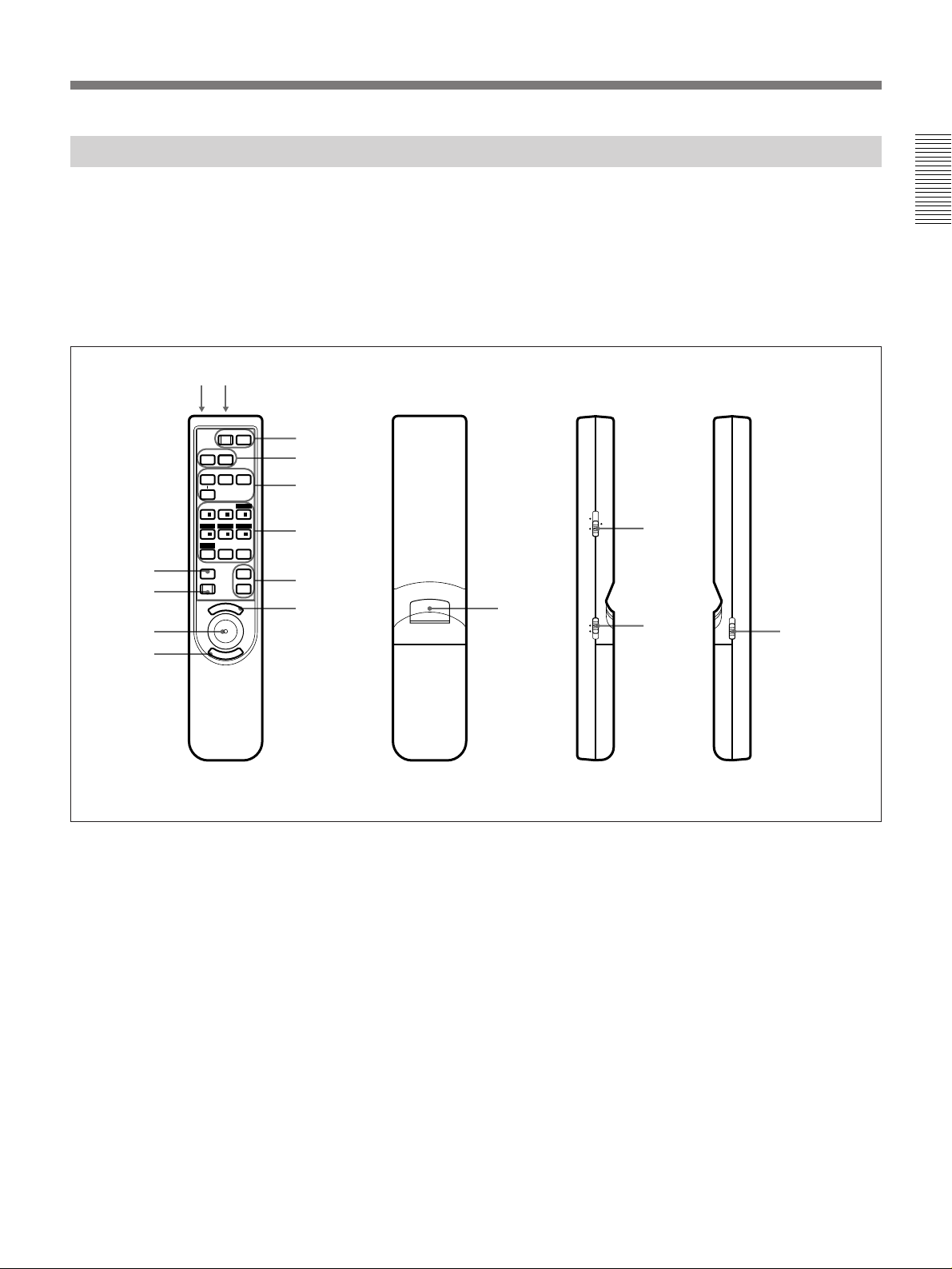
Location and Function of Controls
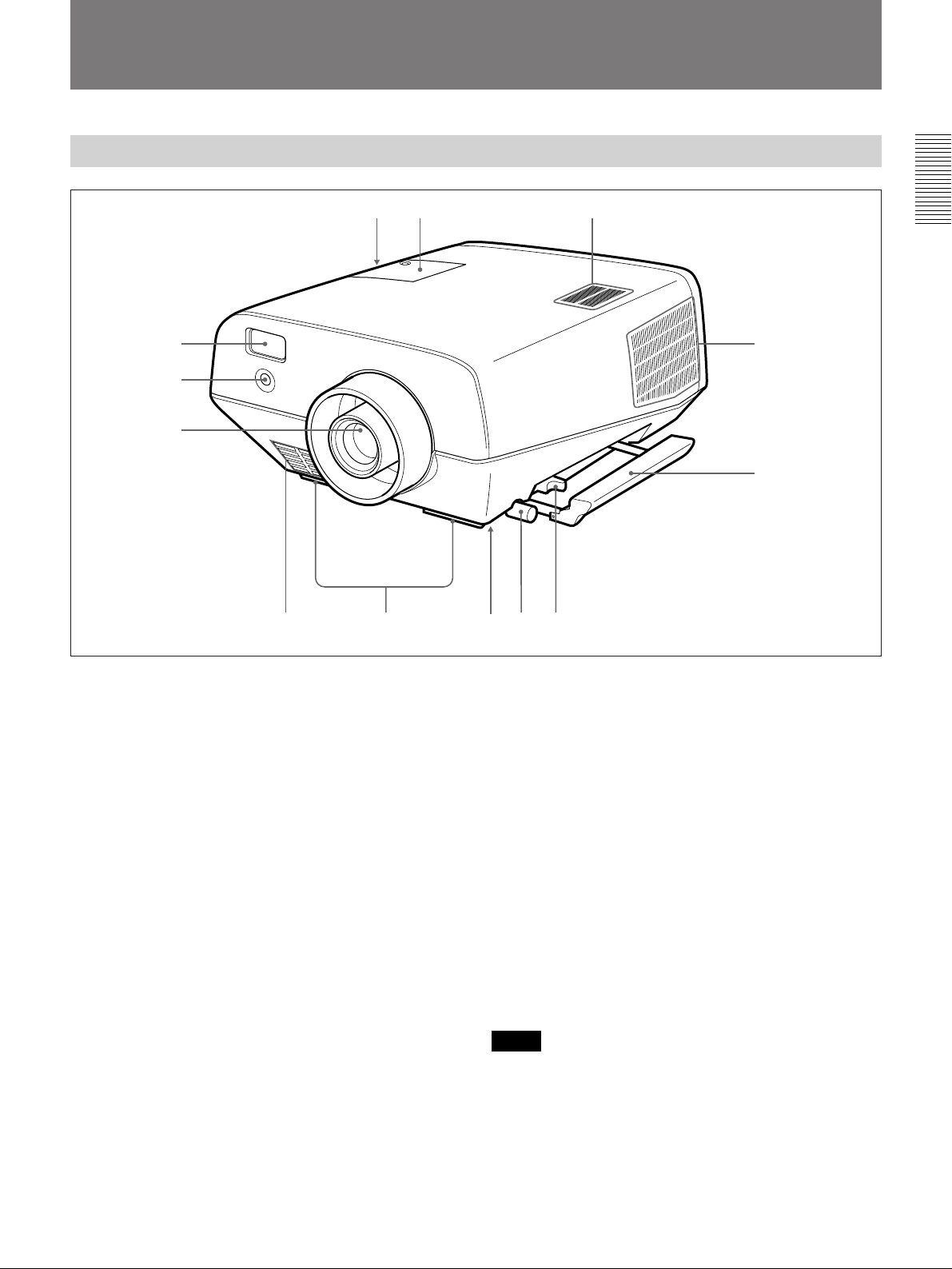
Front
!£ !™ !¡
1
2
3
54 876
1 Remote Commander pocket
Houses the supplied Remote Commander. When
inserting the Remote Commander, make sure the
infrared transmitter is facing forwards and push it until
it clicks.
To take out the Remote Commander from the pocket,
push it once and pull it out.
2 Front remote control detector
!º
9
8 Handle lever
Use the lever for putting away the carrying handle.
9 Carrying handle
Pull out the handle for carrying the projector.
0 Right side ventilation holes (exhaust)
Do not block the holes.
3 Lens
Remove the lens cap before projection.
4 Front ventilation holes (intake)
Do not place anything within the 50 cm (19
range from these holes or block them.
5 Adjusters
Use the adjusters to keep the projector level if it is
installed on an uneven surface.
6 Bottom ventilation holes (exhaust)
Do not block the holes.
7 Adjuster screw
Adjusts the height of the adjuster.
3
/4 inches)
!¡ Speaker
!™ Lamp cover
!£ Left side ventilation holes (intake)
Do not place anything within the 30 cm (11
range from these holes or block them.
Notes
•Do not block the ventilation holes, or internal heat
build-up may occur, causing fire or damage to the
projector.
•Do not place anything near the ventilation holes or
touch these holes as it may cause internal heat buildup.
7
/8 inches)
7 (EN)
Page 8
Location and Function of Controls
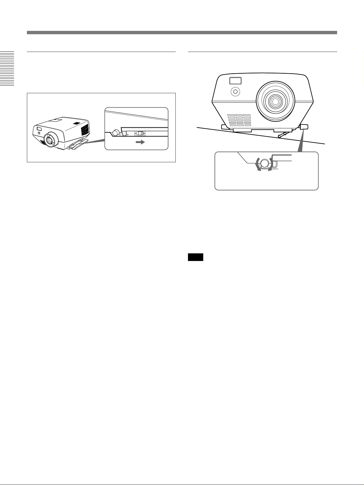
Using the carrying handles
Pull out to use for carrying the projector. To put away
the handle, slide the handle lever backward.
Using the adjusters
To raise
the projector
When turning the screw counterclockwise,
the adjuster comes out.
To lower
the projector
1 While lifting the projector, turn the screw
counterclockwise.
The adjuster comes out.
2 Turn the screw to adjust the height so that the
projector becomes level.
Note
Be careful not to let the projector down on your
fingers.
8 (EN)
Page 9
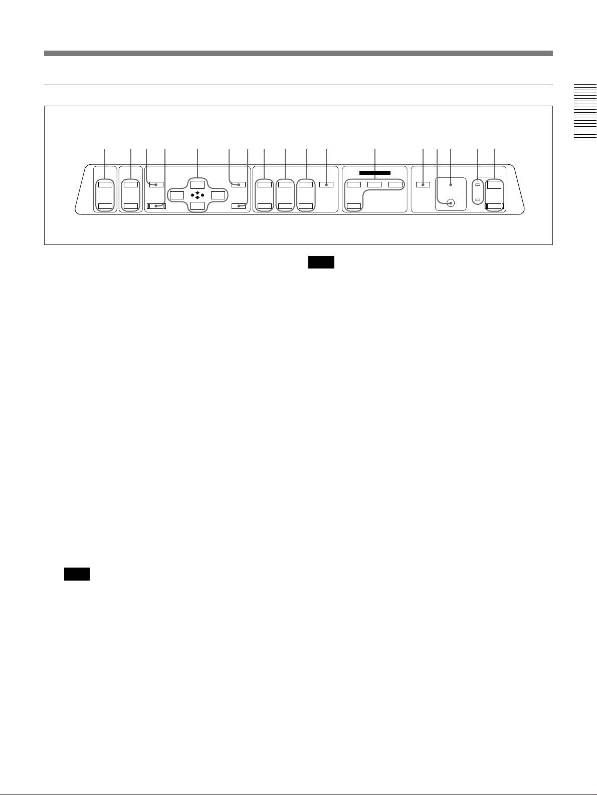
Control panel
!∞ !¢ !™ 4!¡
MUTING
VOLUME
PICTURE
AUDIO
MEMORY
+
–
RESET
MENU
ENTER
SHIFT
+
–
1 POWER keys
ON : Press to turn on the power when the projector is
in the standby mode. The POWER indicator lights
in green when the power is turned on.
OFF : Press to turn off the power.
2 Indicators
POWER: Lights in green when the power is turned
on.
Flashes in green while the cooling fan runs after
turning off the power with the POWER OFF key.
The fan runs for about two minutes after turning
off the power.
The POWER indicator flashes quickly for the first
minute. During this time, you will not be able to
turn the power back on with the POWER ON key.
STANDBYu: Lights in red when the MAIN
POWER switch at the rear of the projector is
turned on.
Once in the standby mode, you can turn on and off
the projector with the POWER ON/OFF keys on
the Remote Commander or the control panel.
Note
When the MAIN POWER switch is turned off,
there will be a slight delay before the STANDBY
indicator goes off.
3 Error code display window
Displays the error codes.
For details on the error codes, see “Error codes” on page
42 (EN).
LENS CONTROL
ZOOM
+
–
PATTERNFOCUS
+
–
VIDEO
SELECT
INPUT SELECT
A
VIDEO/S VIDEO
LIGHTB
STANDBY u
g
Note
When the lamp is warm, it may not light up easily.
In this case, 88 appears in the error code display
window, but this is not malfunction.
If 88 remains lit for more than three minutes after
turning on the power, never open the lamp cover if
the projector is installed on the ceiling.
4 Rear remote control detector
5 LIGHT key
Lights the back lighting for the keys on the control
panel when the projector is turned on. Press again to
turn off the back lighting. If you do not press any key
for 30 seconds, back lighting turns off automatically.
6 INPUT SELECT keys
Select the input signal.
VIDEO: Selects the video signal input from the
VIDEO or S VIDEO connectors and the audio
signal input from the AUDIO IN L/R jacks. To
switch the S VIDEO and VIDEO connectors, use
the SELECT key.
SELECT: Each time you press this key, the input
video signal is switched between the VIDEO and
S VIDEO connectors.
A: Selects the audio and video signals input from the
INPUT A connectors.
B: Selects the signal input from the connectors on the
optional interface board (other than IFB-40) which
is installed in the INPUT B section.
7 PATTERN key
Displays an H pattern on the screen for focus, zoom,
and shift adjustments. Press again to clear the H
pattern.
1237 5!¶ !§ !º 69 8!£
POWER
ON
OFF
(Continued)
9 (EN)
Page 10

Location and Function of Controls
8 FOCUS +/– keys
Adjusts the focus.
+ : Picture focuses forward.
– : Picture focuses farther back.
9 ZOOM +/– keys
Adjusts the zoom.
+ : Picture size is enlarged.
– : Picture size is reduced.
0 SHIFT +/– keys
Adjusts the vertical position of the picture.
+ : Picture moves upward.
– : Picture moves downward.
!¡ ENTER key
Press to enter the settings of items in the menu system.
!™ MENU key
Press to display the on-screen menu. Press again to
clear the menu.
!£ Arrow keys (V/v/B /b)
Used to move the on-screen cursor or to make various
adjustments.
!¢ RESET key
Press to restore the value of an item back to its factory
preset value. This key functions when the menu or a
setting item is displayed on the screen.
!∞ MEMORY key
Stores various adjustment data into memory.
!§ VOLUME +/– keys
Adjust the volume of the built-in speaker and output
level of the AUDIO OUT jacks.
+ : Increases the volume.
– : Decreases the volume.
!¶ MUTING keys
Cuts off the picture or sound temporarily.
PICTURE: Press to cut off the picture. Press again
to restore the picture.
AUDIO: Press to cut off the sound. Press again or
press the VOLUME + key to restore the sound.
10 (EN)
Page 11
Rear
+
1
2
–
U
3
45 67
CONTROL S
IN
PLUG IN
POWER
OUT
S VIDEO
AUDIO OUT
L R
REMOTE
RS-422A
VIDEO
AUDIO IN INPUT A
L R
8 9 !º !¡ !™
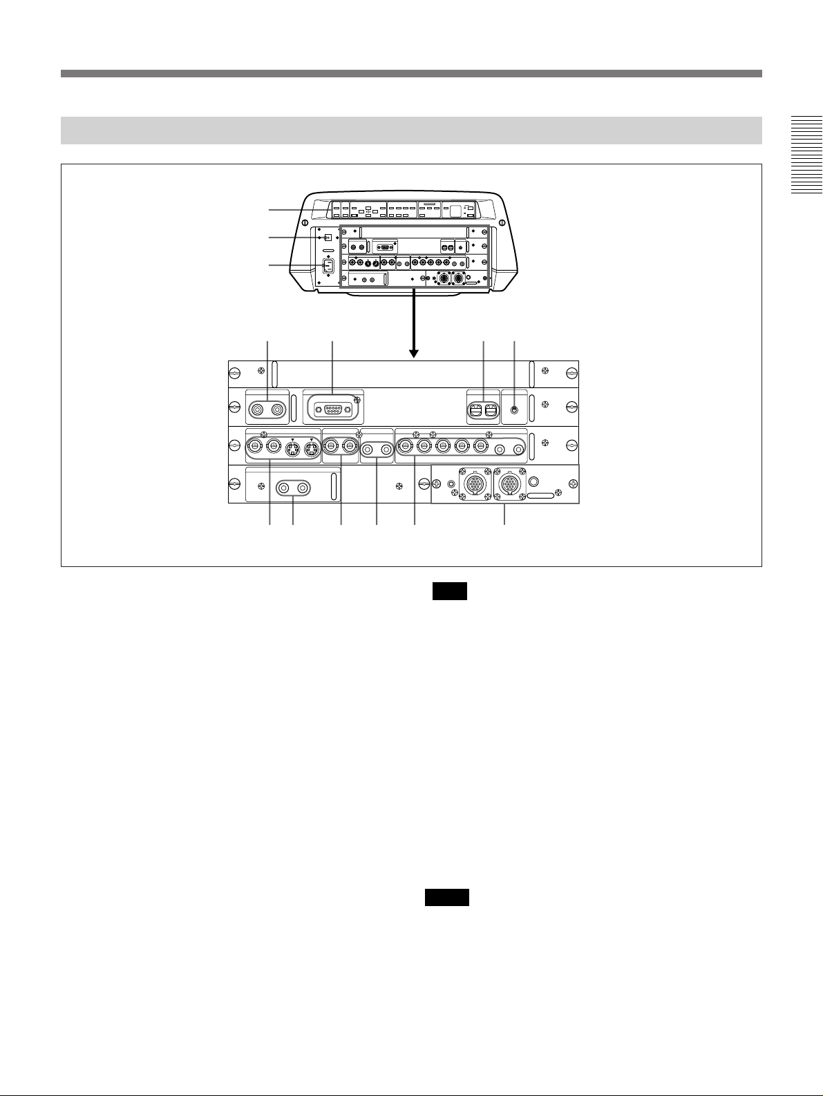
1 Control panel
You can turn the control panel by 180 degrees when
installing the projector upside-down, such as for
ceiling installation. For details, consult with qualified
Sony personnel.
For details on the control panel key arrangement, see
“Control panel” on pages 9 (EN) and 10 (EN).
2 MAIN POWER switch (OON/oOFF)
Turns the main power on and off.
3 AC IN socket
Connect the supplied AC Power cord.
4 CONTROL S IN/OUT jacks (stereo minijack)
Connect to the control S jacks of other Sony
equipment.
CONTROL S IN/PLUG IN POWER (DC 5 V
output) jack: Connects to the CONTROL S OUT
jack of the supplied Remote Commander when
using as a wired Remote Commander. In this case,
you do not need to install the batteries in the
Remote Commander, since the power is supplied
from this jack.
CONTROL S OUT jack: Outputs the control S
signal.
+–+–+
–
G/Y B/B-Y SYNC/HDY IN C IN IN OUT IN OUT VD AUDIO IN
R/R-Y
0 0
REMOTE 1
g
IN
u
INDEX TRIG
0
0
R
L
(MONO)(MONO)
MODE
OUT
!£
Note
When connecting the remote commander cable to the
CONTROL S IN jack, the remote control detectors
will not work.
5 REMOTE RS-422A connector (D-sub 9-pin,
female)
Connect to a computer to operate the projector from a
computer. This expands system capability via the RS422A interface. Before using this connector, remove
the red cap attached at the factory.
6 INDEX switches
Set the index number of the projector when using
multiple projectors. You can set the numbers between
“01” and “99”. It is set to “01” at the factory.
Notes
•Do not set the index number to “00”. If it is set to
“00”, the projector cannot be controlled with the
Remote Commander.
•Do not set the index number to “9” if you use the
supplied Remote Commander for controlling the
projector.
(Continued)
11 (EN)
Page 12
Location and Function of Controls
7 TRIG (trigger output) jack (monaural minijack)
The signal is transmitted from this jack to the
connected equipment whether the projector is on or
off. (This is not a power source for external
equipment.) A singal of approximately 5 V DC is
output when the projector power is on. The signal is
not output when the projector power is off.
8 S VIDEO connectors
Connect to external video equipment, such as a VCR.
The OUT connector can be used as loop-through
output via the Y/C IN or IN connectors.
Y IN/C IN (BNC-type): Connect to the Y and C
video outputs of the video equipment.
IN (mini DIN 4-pin): Connects to the Y/C video
output of the video equipment.
OUT (mini DIN 4-pin): Used as loop-through output
via the Y/C IN connectors or the IN connector.
Note
If you have video equipment connected to both the Y/
C IN and IN connectors, the signal from the Y/C IN
connectors are selected prior to the IN connector.
When showing a video connected to the IN connector,
be sure not to connect any cable to the Y/C IN
connectors.
9 AUDIO OUT L/R jacks (phono type)
Connect to external active speakers.
The volume of the speakers can be controlled by the
VOLUME keys on the Remote Commander or the
control panel.
0 VIDEO connectors (BNC-type)
Connect to external video equipment, such as a VCR.
The VIDEO OUT connector can be used as loopthrough output via the VIDEO IN connector.
IN: Connects to the composite video output
connector of the video equipment.
OUT: Used as loop-through output of the VIDEO IN
connector.
!™ INPUT A connectors
RGB input connectors (R/R-Y, G/Y, B/B-Y,
SYNC/HD, VD) (BNC-type): Connect to such as
the video outputs of a computer or a video camera.
According to the connected equipment, the RGB
or component (R-Y, Y, B-Y) signal is selected.
AUDIO IN L (MONO) /R jacks (phono type):
Connect to the audio output jacks of equipment.
For stereo equipment, use both the L and R jacks;
for monaural equipment, use the L (MONO) jack
only.
!£ Signal interface board attachment part (INPUT
B)
The IFB-40 Signal Interface Board is installed at the
factory. Other optional signal interface boards can be
attached to this section instead of the IFB-40.
For details on installing the interface boards, consult with
qualified Sony personnel.
Indicator (red): Lights up when the REMOTE 1 IN
connector is selected.
REMOTE 1 IN connector (14-pin multi-
connector): Connect to the optional signal
interface switcher. When using two projectors and
this unit is used as the first one, connect to the
REMOTE 1 OUT connector on the IFB-40
installed on the other projector.
REMOTE 1 OUT connector (14-pin multi-
connector): Connect to the REMOTE 1 IN
connector on IFB-40 installed on another projector
when using two projectors and this unit is used as
second one.
MODE selector: Turn the control switch of the
MODE selector to the appropriate position
according to the length of the cable connecting to
the REMOTE 1 OUT connector.
Cable length up to 2 m
Type of cable SIC-M-1 SIC-M-5 SIC-M-15 SIC-M-50
CCQ-2BRS CCQ-10BRS
Position 1 2 3 4
up to 10 m up to 25 m up to 50 m
CCQ-5BRS CCQ-25BRS CCQ-50BRS
SIC-M-25
!¡ AUDIO IN L (MONO) /R jacks (phono type)
Connect to the audio output jacks of equipment. For
stereo equipment, use both the L and R jacks; for
monaural equipment, use the L (MONO) jack only.
12 (EN)
Page 13
Remote Commander
The Remote Commander can be used as a wireless or
wired Remote Commander. The functions of the keys
on the Remote Commander are the same as those on
the control panel of the projector.
For details on control panel keys on the projector, see pages
9 (EN) and 10 (EN).
!™ !£
POWER
OFF
!¡
!º
MUTING
AUDIO
INPUT SELECT
SELECT
VIDEO/S VIDEO
SWITCHER
+
1/
4/ – 5/ – 6/
PATTERN
MEMORY
RESET
M
PIC
AVIDEO
2/ + 3/
ZOOMSHIFT
87 ALL
E
ON
B
/ LENS /INDEX
+
FOCUS
–
SECOND
+
VOLUME
–
N
U
1
2
3
5
6
7
9
E
R
N
E
8
T
If you use the optional RM-PJ20/PJ21 Mouse
Receiver, you can use the Remote Commander as a
mouse for a connected computer.
For details, refer to the instruction manual supplied with the
RM-PJ20/PJ21 Mouse Receiver.
INDEX
LENS SWITCHER
8
MOUSE MENU
4
!¢
LIGHT
!∞
Front Rear Side (R) Side (L)
1 POWER ON/OFF keys
2 MUTING PIC/AUDIO keys
The MUTING PIC key has the same function as the
MUTING PICTURE key on the control panel.
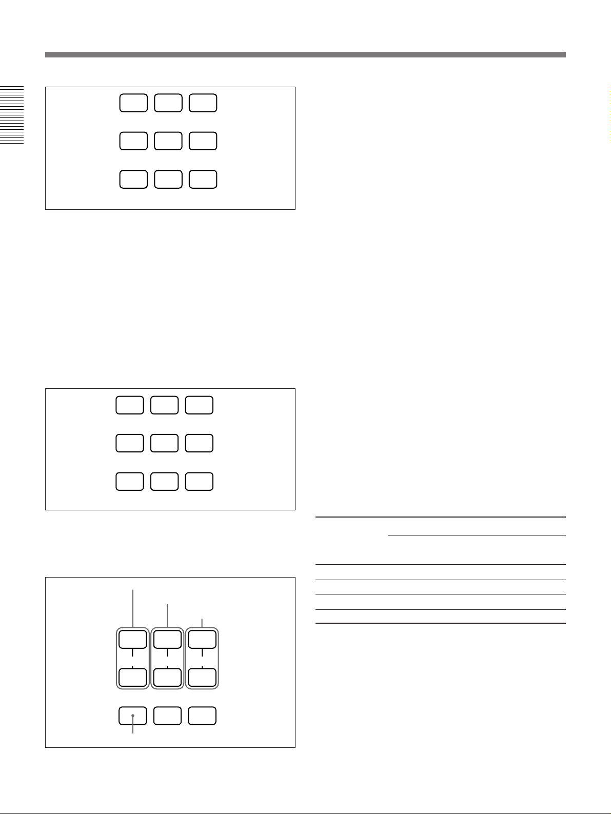
3 INPUT SELECT/ VIDEO/A/B/SELECT keys
4 SWITCHER/INDEX/LENS selector
Switches the function of the SWITCHER/INDEX/
LENS keys.
SWITCHER: For designating the input from the
optional switcher.
INDEX: For selecting the projector to be operated
when multiple projectors are used in one system.
LENS: For adjsting the focus, zoom, shift, and
displaying or clearing the H pattern.
5 SWITCHER/INDEX/LENS keys
These keys function as follows depending on the
position of the SWITCHER/INDEX/LENS selector.
When the SWITCHER/INDEX/LENS selector is
set to SWITCHER position
Designate the input from the switcher when the
optional signal interface switcher is connected. The
SECOND key is used when two switchers are
connected. To select the input from the second
switcher, press a number key between 1 and 8 within
two seconds after pressing the SECOND key.
(Continued)
13 (EN)
Page 14
Location and Function of Controls
1
23
6 VOLUME +/– keys
7 MENU key
4
Designate the input from the switcher.
56
SECOND
87
When the SWITCHER/INDEX/LENS selector is
set to INDEX
Used to designate the projector to be operated when
multiple projectors are used in one system.
You can designate the projector by pressing the index
number which you have set on the projector.
Example: When pressing [5] first and then [ENTER],
the next operation will be effective only on
the projector on which the index number
has been set to “5”. When operating all the
projectors at the same time, press [ALL]
first, then [ENTER].
1 23
4
Designate the projector to be operated.
56
87 ALL
8 ENTER keys
9 Joy stick
Used to move the on-screen cursor or to make various
adjustments.
0 RESET key
!¡ MEMORY key
!™ CONTROL S OUT jack (stereo minijack)
Connect to the CONTROL S IN jack on the projector
when using the Remote Commander as a wired
Remote Commander. In this case, you do not need to
install the batteries since the power is supplied from
the CONTROL S IN jack on the projector.
!£ Infrared transmitter
!¢ MOUSE/MENU switch
Normally, set to MENU. Set to MOUSE when you
operate the mouse function of a computer connected to
the optional RM-PJ20/PJ21 Mouse Receiver from the
Remote Commander.
When the MOUSE/MENU switch is set to MOUSE,
the MENU, ENTER keys, and joy stick function as
follows.
1)
Function
2), 3)
Macintosh
4)
When the SWITCHER/INDEX/LENS selector is
set to LENS
Used to adjust focus, zoom, shift and to display or
clear the H pattern on the screen.
Adjust the shift.
Adjust the zoom.
Adjust the focus.
+
–
PATTERN
Displays or clears the H pattern.
++
FOCUSZOOMSHIFT
––
Key
IBM PC/AT
compatible, NEC
MENU Left button Mouse button
ENTER (front) Right button Mouse button
ENTER (rear) Right button Mouse button
Joy stick
Corresponds with the movements of the mouse
!∞ LIGHT switch
Lights the back lighting for the keys on the Remote
Commander. Press again to turn off the back lighting.
If you do not press any key for 30 seconds, back
lighting turns off automatically.
..........................................................................................................................................................................................................
1) IBM PC/AT is a registered trademark of International Business Machines Corporation, USA.
2) NEC is a registered trademark of NEC Corporation.
14 (EN)
3) RM-PJ21 does not function with NEC computers.
4) Macintosh is a registered trademark of Apple Computer, Inc.
Page 15
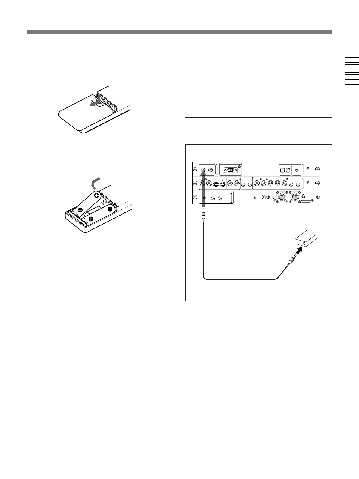
Battery installation
1 Push and slide to open the lid.
•The remote control detectors on the projector do not
operate when connecting the remote commander
cable to the CONTROL S IN jack. If you wish to use
the Remote Commander as a wireless Remote
Commander, be sure to remove the remote
commander cable from both the Remote Commander
and the projector.
To connect the Remote Commander to the
projector
2 Install the two size AA (R6) batteries (supplied)
with the correct polarity.
Be sure to install
the battery from
the ’ side.
3 Replace the lid.
Notes on batteries
•Be careful that the battery orientation is correct when
inserting batteries.
•Do not mix old battery with new one, or different
types of batteries.
•If you do not intend to use the Remote Commander
for a long time, remove the batteries to avoid damage
from battery leakage. If a battery has leaked, remove
the batteries, wipe the battery compartment dry and
replace the batteries with new ones.
Notes on wireless Remote Commander
operation
•Be sure that there is nothing to obstruct the infrared
beam between the Remote Commander and the
projector.
•The operation range is limited. The shorter the
distance between the Remote Commander and the
projector, the wider the angle within which the
commander can control the projector.
Rear
CONTROL S
OUT
IN
PLUG IN
POWER
to CONTROL S IN
Stereo remote
commander cable
(supplied)
S VIDEO
AUDIO OUT
L R
REMOTE
RS-422A
VIDEO
AUDIO IN INPUT A
L R
G/Y B/B-YSYNC/HDY IN C IN IN OUT IN OUT VD AUDIO IN
R/R-Y
REMOTE 1
IN
to CONTROL
S OUT
INDEX TRIG
0
0
R
L
(MONO)(MONO)
MODE
OUT
Remote Commander
Note on wired Remote Commander operation
using the supplied stereo remote commander
cable
If the MOUSE/MENU switch is set to MENU to
operate the projector, you do not need to install the
batteries since the power is supplied from the
CONTROL S IN jack on the projector. In this case, the
batteries are not consumed.
15 (EN)
Page 16

Installing the Projector
This section describes the installation arrangements for installing the
projector on a table. For ceiling installation, consult with qualified Sony
personnel (see page 36 (EN)).
Horizontal center
of the screen
Vertical
center of
the screen
Installation
area
Projection distance
Install the projector so that the tip of the lens is
within this area.
Adjust the vertical and horizontal positioning of the
projector.
Vertical positioning (side view)
Screen
0
0
You can adjust the angle of the lens by adjusting the
SHIFT +/– keys (page 20 (EN)) or PICTURE SHIFT
0
0
in the SET SETTING menu (page 29 (EN)).
Set the projector so that the center of the lens is
between just below the bottom edge of the screen
and the center of the screen.
Horizontal positioning (top view)
Screen
Adjustable range
Center of the unit
56 mm
(2 1/4 inches)
Center of the lens
Adjust the horizontal positioning of the projector so that the
lens is aligned with the horizontal center of the screen.
The distance between the lens and the screen varies depending
on the size of the screen. Use the following table as a guide.
Unit: m (feet)
Screen size (inches) 40 60 80 100 120 150 180 200 250 300
Distance
Minimum 1.5 (4.9) 2.3 (7.5) 3.1 (10.1) 3.9 (12.7) 4.7 (15.4) 5.9 (19.3) 7.1 (23.2) 7.9 (25.8) 9.9 (32.3) 11.9 (38.9)
Maximum 2.3 (7.7) 3.5 (11.5) 4.7 (15.5) 5.9 (19.3) 7.1 (23.3) 8.9 (29.3) 10.7 (35.1) 11.9 (39.2) 15.0 (49.0) 18.0 (58.9)
For detailed information on installation measurements, see page 35 (EN).
16 (EN)
Page 17

Connecting with a Computer or a VCR
This section describes how to connect the projector with a computer, VCR,
and external active speakers. For details on how to connect other
equipment, see pages 37 (EN) to 39 (EN).
Also refer to the instruction manuals of the equipment to be connected.
When making connections, be sure to:
•turn off all equipment before making any connections.
•use the proper cables for each connection.
•insert the plugs of the cables properly; plugs that are not fully inserted
often generate noise. When pulling out a cable, be sure to pull it out from
the plug, not the cable itself.
VCR
Setting up and projecting
to a wall outlet
AC power cord
(supplied)
Rear
to AC IN
U
+
–
Front
+–+–+
–
Audio cable
(not supplied)
to S VIDEO OUT
S video cable (not supplied)
u
g
0 0
CONTROL S
IN
PLUG IN
POWER
ç
SMF-400 Monitor Cable
(5BNC˜HD D-sub 15-pin)
(not supplied)
OUT
S VIDEO
AUDIO OUT
L R
ç
to
VIDEO
OUT
ç
REMOTE
RS-422A
VIDEO
AUDIO IN INPUT A
L R
to AUDIO OUT
Audio cable (not supplied)
ç
Video cable
(not supplied)
G/Y B/B-YSYNC/HDY IN C IN IN OUT IN OUT VD AUDIO IN
R/R-Y
REMOTE 1
IN
ç
INDEX TRIG
0
0
L
(MONO)(MONO)
ç
R
MODE
OUT
Audio cable
(not supplied)
ç: Signal flow
Use the optional ADP-20 Signal
Adapter when connecting with a
Macintosh computer.
Active speakers
Computer
Note
Set the INPUT-A item in the SET SETTING menu to RGB.
For details, see page 30 (EN).
17 (EN)
Page 18

Projecting
1
MAIN POWER
U
ØON/øOFF
Front remote control detector
STANDBY indicator
2
POWER indicator
Rear remote control detector
6
4
MUTING
VOLUME
PICTURE
+
–
U
+–+–+
–
u
g
0 0
MEMORY
+
AUDIO
RESET
–
LENS CONTROL
MENU
SHIFT
ZOOM
+
+
ENTER
–
–
PATTERNFOCUS
+
–
INPUT SELECT
VIDEO LIGHT
BA
SELECT
VIDEO/S VIDEO
38 5,7
AUDIO
3
SELECT
SWITCHER
1/
8
4/ – 5/ – 6/
PATTERN
4
MEMORY
RESET
g
POWER
OFF
MUTING
PIC
INPUT SELECT
AVIDEO
VIDEO/S VIDEO
+
2/ + 3/
ZOOMSHIFT
87 ALL
N
E
M
U
STANDBY u
ON
/ LENS /INDEX
FOCUS
SECOND
VOLUME
POWER
ON
OFF
2
B
+
5, 7
–
6
+
–
E
R
N
E
T
1 Press the MAIN POWER switch on the rear of the projector (O ON).
The STANDBY indicator lights in red and the projector goes into the
standby mode.
2 Press the POWER ON key on the Remote Commander or the control
panel.
The POWER indicator lights in green.
18 (EN)
Page 19

3 Switch on equipment connected to the projector. Press the INPUT
SELECT keys on the Remote Commander or the control panel to
select the input source.
VIDEO: Selects the video signal input from the VIDEO or S
VIDEO connectors and the audio signal input from the
AUDIO IN L/R jacks. To switch the VIDEO or S VIDEO
connectors, use the SELECT key.
SELECT: Each time you press this key, the input signal is switched
between VIDEO and S VIDEO.
A: Selects the audio and video signals input from the INPUT
A connectors.
B: Selects the signal input from the connectors on the optional
interface board (other than IFB-40) which is installed in the
INPUT B section.
When you input the signal from equipment connected to the optional
signal interface switcher, set the SWITCHER/INDEX/LENS selector
on the Remote Commander to the SWITCHER position and designate
the channel number by pressing the number keys.
4 Set the SWITCHER/INDEX/LENS selector to the LENS position, and
then press the PATTERN key on the Remote Commander or the
control panel to display the H pattern.
HHHH HHHH
HHHH HHHH
HHHH
HHHH
HHHH HHHH
HHHH HHHH
Press the PATTERN key again to clear the H pattern.
5 Press the FOCUS +/– key on the Remote Commander or the control
panel to adjust the focus.
“FOCUS” appears on the screen during adjustment.
6 Press the ZOOM +/– key on the Remote Commander or the control
panel to adjust the zoom.
“ZOOM” appears on the screen during adjustment.
7 Press the FOCUS +/– key on the Remote Commander or the control
panel again to adjust the focus.
“FOCUS” appears on the screen during adjustment.
(Continued)
19 (EN)
Page 20

Projecting
8 Press the SHIFT +/– key on the Remote Commander or the control
panel to adjust the vertical position of the picture.
“PICTURE SHIFT” appears on the screen during adjustment.
To Press
Adjust the volume the VOLUME +/– keys.
Cut off the sound the AUDIO MUTING key (also cut off
the signal output from the AUDIO OUT
jacks.) To restore the sound, press the
AUDIO MUTING key again or press
the VOLUME + key.
Cut off the picture the PICTURE MUTING key (PIC
MUTING key on the Remote
Commander). To restore the picture,
press the PICTURE MUTING key
again.
To turn off the power
Notes
•Do not look into the lens when the projector lamp is on.
•When you adjust the focus, zoom, and shift with the Remote
Commander, be sure to set the SWITCHER/INDEX/LENS selector to the
LENS position.
1 Press the POWER OFF key on the Remote Commander or the control
panel.
The POWER indicator flashes in green and the cooling fan keeps
running for about two minutes to reduce the internal heat. The POWER
indicator flashes quickly for the first minute. During this time, you will
not be able to turn the power back on. After about one minute, you can
turn on the power with the POWER ON key.
2 Wait until the fan stops running and the STANDBY indicator lights in
red; then press the MAIN POWER switch to turn off the main power
(o OFF).
Notes
• Do not press the MAIN POWER switch while the fan is still
running; the fan will stop while the lamp is still hot, leading to
breakdown.
• To make the lamp life last longer, do not turn off the power at least
for about 10 minutes after turning on the power.
20 (EN)
Page 21

Using the MENU
Adjustments and settings using the menu
The projector is equipped with an on-screen menu for
making various adjustments and settings. Adjustable
items are displayed in green.
To select the language used in the menu, see page
30 (EN).
1 Press the MENU key.
The menu display appears.
The menu presently selected is highlighted in blue.
INPUT-A
VIDEO:VIDEO
INPUT
SELECT
INPUT-A
PICTURE
INPUT-B
AUDIO
CTRL
SWITCHER:SW'ER1-1
INPUT
SETTING
SET
SETTING
INPUT
INFO.
SEL: EXIT: MENU
2 Use the V or the v key on the control panel to
select a menu, then press the b or the ENTER key.
On the Remote Commander, move the joy stick up
or down to select a menu, then move it to the right
or press the ENTER key.
The selected menu appears.
Menus Setting items
INPUT-A
CONTRAST 80
INPUT
SELECT
BRIGHT 50
PICTURE
COLOR 50
AUDIO
CTRL
HUE 50
SHARP 50
INPUT
SETTING
D.PICTURE:ON
COLOR SYS:AUTO
SET
SETTING
VOLUME 50
INPUT
INFO.
SEL:
SET: ENTER
RESET: RESET
EXIT: MENU
To clear the menu display
Press the MENU key. The menu display also
disappears automatically if no key is pressed for one
minute.
To reset settings that have been adjusted
Press the RESET key. “RESET complete!” appears on
the screen and the settings appearing on the screen will
be reset to their factory preset values.
Items that can be reset are as follows:
“CONTRAST”, “BRIGHT”, “COLOR”, “HUE”,
“SHARP”, “DOT PHASE”, “SIZE”, and “SHIFT”.
About the memory of the settings
The settings are automatically stored in the projector
memory. Also, every time you press the MEMORY
key on the Remote Commander or the control panel,
the settings are stored in the projector memory
automatically.
3 Make setting or adjustment on an item.
For details on setting individual items, see the relevant
menu pages.
21 (EN)
Page 22

The INPUT SELECT Menu
The INPUT SELECT menu is used for selecting the
input signal.
VIDEO
VIDEO:VIDEO
INPUT
SELECT
INPUT-A
PICTURE
INPUT-B
AUDIO
CTRL
SWITCHER:SW'ER1-1
INPUT
SETTING
SET
SETTING
INPUT
INFO.
SEL: EXIT: MENU
Operation
Use the V or the v key on the control panel to select
the input, then press the ENTER key.
On the Remote Commander, move the joy stick up or
down to select the input, press the ENTER key.
VIDEO
Selects the video signal input from the VIDEO or S
VIDEO connectors and the audio signal input from the
AUDIO IN L/R jacks.
INPUT-A
Selects audio and video signals input from the INPUT
A connectors.
INPUT-A
VIDEO:VIDEO
INPUT
SELECT
INPUT-A
PICTURE
INPUT-B
AUDIO
CTRL
SWITCHER:SW'ER1-1
INPUT
SETTING
SET
SETTING
INPUT
INFO.
SEL: EXIT: MENU
INPUT-B
Selects the signal input from the connectors on the
optional interface board (other than IFB-40) which is
installed in the INPUT B section.
INPUT-B
VIDEO:VIDEO
INPUT
SELECT
INPUT-A
PICTURE
INPUT-B
AUDIO
CTRL
SWITCHER:SW'ER1-1
INPUT
SETTING
SET
SETTING
INPUT
INFO.
SEL: EXIT: MENU
VIDEO
VIDEO:VIDEO
INPUT
SELECT
INPUT-A
PICTURE
INPUT-B
AUDIO
CTRL
SWITCHER:SW'ER1-1
INPUT
SETTING
SET
SETTING
INPUT
INFO.
SEL: EXIT: MENU
Press the b key so that the following pop-up menu
appears.
VIDEO
VIDEO VIDEO
INPUT
SELECT
INPUT S-VIDEO
PICTURE
INPUT-B
AUDIO
CTRL
SWITCHER:SW'ER1-1
INPUT
SETTING
SET
SETTING
INPUT
INFO.
SEL:
SET: ENTER
RESET: RESET
EXIT: MENU
Use the V or the v key on the control panel to select
the input, then press the ENTER key.
On the Remote Commander, move the joy stick up or
down to select the input, then press the ENTER key.
If you select S-VIDEO when you have video
equipment connected to both the Y IN/C IN and IN
connectors, the signals from the Y IN/C IN connectors
are selected.
SWITCHER
Selects the signal from equipment connected to the
optional signal interface switcher.
SW'ER1-1
VIDEO:VIDEO
INPUT
SELECT
INPUT-A
PICTURE
INPUT-B
AUDIO
CTRL
SWITCHER:SW'ER1-1
INPUT
SETTING
SET
SETTING
INPUT
INFO.
Press the b key so that the following pop-up menu
appears.
SW'ER1-1
VIDEO:VID SW'ER1-1
INPUT
SELECT
INPUT-A SW'ER1-2
PICTURE
INPUT-B SW'ER1-3
AUDIO
CTRL
SWITCHER: SW'ER1-4
SW'ER1-5
INPUT
SETTING
SW'ER1-6
SW'ER1-7
SET
SETTING
SW'ER1-8
INPUT
INFO.
SEL:
Use the V or the v key on the control panel to select
the input, then press ENTER key.
On the Remote Commander, move the joy stick up or
down to select the input, then press the ENTER key.
SET: ENTER
SEL: EXIT: MENU
RESET: RESET
EXIT: MENU
22 (EN)
Page 23

The PICTURE AUDIO CTRL Menu
The PICTURE AUDIO CTRL menu is used for
adjusting the picture and volume. Adjustable items are
displayed in green.
VIDEO
CONTRAST 80
INPUT
SELECT
BRIGHT 50
PICTURE
COLOR 50
AUDIO
CTRL
HUE 50
SHARP 50
INPUT
SETTING
D.PICTURE:ON
COLOR SYS:AUTO
SET
SETTING
VOLUME 50
INPUT
INFO.
SEL: EXIT: MENU
Operation
1. Select an item
Use the V or the v key on the control panel to select
the item, then press the b or the ENTER key.
On the Remote Commander, move the joy stick up or
down to select the item, then move it to the right or
press the ENTER key.
CONTRAST
Adjusts the picture contrast.
CONTRAST: 80
The higher the setting, the greater the contrast.
The lower the setting, the lower the contrast.
BRIGHT
Adjusts the picture brightness.
BRIGHT: 50
The higher the setting, the brighter the picture.
The lower the setting, the darker the picture.
COLOR
2. Adjust an item
• When changing the adjustment level:
To increase the number, press the V or the b key.
On the Remote Commander, move the joy stick up
or to the right.
To decrease the number, press the v or the B key.
On the Remote Commander, move the joy stick
down or to the left.
Press the ENTER key to restore the original screen.
• When changing the setting:
Press the V or the v key on the control panel to
change the setting, then press the B or the ENTER
key.
On the Remote Commander, move the joy stick up
or down to change the setting, then move it to the left
or press the ENTER key.
Adjusts color intensity.
COLOR: 50
The higher the setting, the greater the intensity.
The lower the setting, the lower the intensity.
HUE
Adjusts skin tones.
HUE: 50
At high settings, the picture becomes greenish.
At low settings, the picture becomes purplish.
SHARP
Adjusts the picture sharpness.
SHARP: 50
The higher the setting, the sharper the picture.
The lower the setting, the softer the picture.
(Continued)
23 (EN)
Page 24

The PICTURE AUDIO CTRL Menu
D. (Dynamic) PICTURE
Emphasizes the black color.
VIDEO
CONTRAST 80
INPUT
SELECT
BRIGHT 50
PICTURE
COLOR 50
AUDIO
CTRL
HUE 50
SHARP 50
INPUT
SETTING
D.PICTURE: ON
COLOR SYS: OFF
SET
SETTING
VOLUME 50
INPUT
INFO.
SEL:
SET: ENTER
RESET: RESET
EXIT: MENU
ON: Emphasizes the black color to produce a bolder
“dynamic” picture.
OFF: Reproduces the dark portions of the picture
accurately, in accordance with the source signal.
COLOR SYS (System)
Selects the color system of the input signal.
VIDEO
CONTRAST 80
INPUT
SELECT
BRIGHT 50
PICTURE
COLOR AUTO
AUDIO
CTRL
HUE NTSC3.58
SHARP PAL
INPUT
SETTING
D.PICTURE: SECAM
COLOR SYS: NTSC4.43
SET
SETTING
VOLUME PAL-M
INPUT
INFO.
SEL:
SET: ENTER
RESET: RESET
EXIT: MENU
Items that cannot be adjusted depending
on the types of input signal
Item Cannot be adjusted with
COLOR RGB signal, black and white signal
HUE Input signal other than NTSC1) 3.58/4.43
SHARP RGB signal
D. PICTURE RGB signal
COLOR SYS Signal input from INPUT A connectors
Normally, set to AUTO.
If the picture is distorted or colorless, select the color
system according to the input signal.
VOLUME
Adjusts the volume.
VOLUME: 50
The higher the setting, the higher the volume.
The lower the setting, the lower the volume.
..........................................................................................................................................................................................................
24 (EN)
1) NTSC4.43 is the color system used when playing back a video recorded on NTSC on a NTSC4.43 system VCR.
Page 25

The INPUT SETTING Menu
The INPUT SETTING menu is used to adjust the input
signal. Adjustable items are displayed in green.
<page 1>
INPUT-A
DOT PHASE:64
INPUT
SELECT
SIZE
PICTURE
H:800 V:156
AUDIO
CTRL
SHIFT
H:2000 V:2000
INPUT
SETTING
H FILTER:ON
V FILTER:OFF
SET
SETTING
CLAMP:AUTO
INPUT
INFO.
SEL: EXIT: MENU
<page 2>
INPUT-A
COLOR TEMP:HIGH
INPUT
SELECT
SIG PROCESS:FRAME
PICTURE
AUDIO
CTRL
INPUT
SETTING
SET
SETTING
INPUT
INFO.
SEL:
SET: ENTER
RESET: RESET
EXIT: MENU
The INPUT SETTING menu consists of two pages.
To change the page, press the v or the V key until the
page changes when selecting an item.
On the Remote Commander, move the joy stick up or
down until the previous or next page changes when
selecting an item.
Operation
1. Select an item
Use the V or v key on the control panel to select the
item, then press the b or the ENTER key.
On the Remote Commander, move the joy stick up or
down to select the item, then move it to the right or
press the ENTER key.
• When changing the setting:
Press the V or the v key to change the setting and
press the B or the ENTER key.
On the Remote Commander, move the joy stick up
or down to change the setting, then move to the left
or press the ENTER key.
The original screen is restored.
DOT PHASE
Adjusts the dot phase of the LCD panel and the signal
when H FILTER is set to OFF.
Adjust the value to obtain the clearest picture.
DOT PHASE: 64
SIZE
Adjusts the horizontal size of pictures.
SIZE H: 800 V: 156
As the setting for H increases, the horizontal size of
the picture becomes larger, and as the setting
decreases, the size becomes smaller.
As the setting for V increases, the vertical size of the
picture becomes larger, and as the setting decreases,
the size becomes smaller.
Use the B or the b key to adjust the horizontal size and
the V or the v key for the vertical size.
(Continued)
2. Adjust an item
• When changing the adjustment level:
To increase the number, press the V or the b key.
On the Remote Commander, move the joy stick up
or to the right.
To decrease the number, press the v or the B key.
On the Remote Commander, move the joy stick
down or to the left.
Press the ENTER key to restore the original screen.
25 (EN)
Page 26

The INPUT SETTING Menu
SHIFT
Adjusts the position of the picture.
SHIFT H:2000 V:2000
H adjusts the horizontal position of the picture.
V adjusts the vertical position of the picture.
As the setting for H increases, the picture moves to the
right, and as the setting decreases, the picture moves to
the left.
As the setting for V increases, the picture moves up,
and as the setting decreases, the picture moves down.
Use the B or the b key to adjust the horizontal position
and the V or the v key for the vertical position.
H FILTER
Corrects the vertical bands that appear on the picture.
INPUT-A
DOT PHASE:64
INPUT
SELECT
SIZE
PICTURE
H:800 V:156
AUDIO
CTRL
SHIFT
H:2000 V:2000
INPUT
SETTING
H FILTER: ON
V FILTER: OFF
SET
SETTING
CLAMP:AUTO
INPUT
INFO.
SEL: SET: ENTER
RESET: RESET
EXIT: MENU
CLAMP
Corrects the luminance of the picture.
INPUT-A
DOT PHASE:64
INPUT
SELECT
SIZE
PICTURE
H:800 V:156
AUDIO
CTRL
SHIFT
H:2000 V:2000
INPUT
SETTING
H FILT AUTO
V FILT SonG
SET
SETTING
CLAMP: H/C
INPUT
INFO.
SEL: SET: ENTER
CLAMP is used as a standard for setting the black
level of a picture correctly. The standard position of
the clamp depends on the kind of sync signal being
used. Normally, the projector CPU judges the signal
and sets the position automatically. However, the CPU
can misjudge the signal because of noise. If the
luminance of the picture seems to be incorrect (too
dark, the black color is too light, or the luminance is
unstable) the clamp position may need to be changed.
AUTO: Automatic setting mode. Normally set to this
position.
SonG: Set to this position if the black seems too light
or greenish.
H/C: Set to this position if the picture is too dark or
luminance is unstable.
RESET: RESET
EXIT: MENU
These vertical bands may occur when an RGB signal
which horizontal resolution is other than 640 dots is
input. In such cases, set to ON. The picture will loose
some clarity, but the vertical bands will be reduced.
Set to OFF to associate a dot of the input signal with a
pixel of the LCD.
V FILTER
Corrects the horizontal bands that appear on the
picture.
INPUT-A
DOT PHASE:64
INPUT
SELECT
SIZE
PICTURE
H:800 V:156
AUDIO
CTRL
SHIFT
H:2000 V:2000
INPUT
SETTING
H FILTER: ON
V FILTER: OFF
SET
SETTING
CLAMP:AUTO
INPUT
INFO.
SEL: SET: ENTER
These horizontal bands may occur when an RGB
signal which vertical resolution is other than 480 dots
is input. In such cases, set to ON. The picture will
loose some clarity, but the horizontal bands will be
reduced. Set to OFF to associate a dot of the input
signal with a pixel of the LCD.
RESET: RESET
EXIT: MENU
Note
If the luminance is still incorrect after changing the
clamp setting, check the input signal and the
connections.
COLOR TEMP
Adjusts the color temperature.
INPUT-A
COLOR TEMP: HIGH
INPUT
SELECT
SIG PROCESS LOW
PICTURE
HBM
AUDIO
CTRL
INPUT
SETTING
SET
SETTING
INPUT
INFO.
SEL: SET: ENTER
HIGH: Makes the white color bluish.
LOW: Makes the white color reddish.
HBM (High Brightness Mode): Reproduces a
picture with high brightness.
RESET: RESET
EXIT: MENU
26 (EN)
Page 27

SIG PROCESS
Selects the conversion format from the frame format or
field format when the signal is input.
INPUT-A
COLOR TEMP:HIGH
INPUT
SELECT
SIG PROCESS: FRAME
PICTURE
FIELD
AUDIO
CTRL
INPUT
SETTING
SET
SETTING
INPUT
INFO.
SEL: SET: ENTER
RESET: RESET
EXIT: MENU
FRAME: Selects the frame format. This position is
suitable for a still picture.
FIELD: Selects the field format. This position is
suitable for a moving picture.
Items that cannot be adjusted depending
on the types of input signal
Item Cannot be adjusted with
DOT PHASE Signal input from VIDEO IN connectors,
H FILTER Signal input from VIDEO IN connectors,
V FILTER Signal input from VIDEO IN connectors,
CLAMP Signal input from VIDEO IN connectors,
SIG PROCESS
component input signal (15k), 15k RGB
Singal input
component input signal (15k), 15k RGB
singal input
component input signal (15k), 15k RGB
singal input
component input signal (15k)
RGB singal input other than 15 kHz one
27 (EN)
Page 28

The SET SETTING Menu
The SET SETTING menu is used for changing the set
settings of the projector. Adjustable items are
displayed in green.
<page 1>
INPUT-A
FOCUS
INPUT
SELECT
ZOOM
PICTURE
PICTURE SHIFT
AUDIO
CTRL
STATUS:ON
PIC MUTING:OFF
INPUT
SETTING
AUDIO MUTING:OFF
INPUT-A:COMPONENT
SET
SETTING
INPUT-B:RGB
INPUT
INFO.
SEL: EXIT: MENU
<page 2>
INPUT-A
SPEAKER:ON
INPUT
SELECT
LANGUAGE:ENGLISH
PICTURE
H POLARITY:NORMAL
AUDIO
CTRL
V POLARITY:NORMAL
HALF TONE:OFF
INPUT
SETTING
INDEX:01
SET
SETTING
INPUT
INFO.
SEL:
SET: ENTER
RESET: RESET
EXIT: MENU
2. Adjust an item
• When changing the adjustment level:
To increase the number, press the V or the b key.
On the Remote Commander, move the joy stick up
or to the right.
To decrease the number, press the v or the B key.
On the Remote Commander, move the joy stick
down or to the left.
Press the ENTER key to restore the original screen.
• When changing the setting:
Press the V or the v key to change the setting, then
press the B or the ENTER key.
On the Remote Commander, move the joy stick up
or down to change the setting and move it to the left
or press the ENTER key to restore the original
screen.
FOCUS
Adjusts the focus.
When selecting this item, you can display the H
pattern on the screen for fine adjustment.
<page 3>
INPUT-A
POWER SAVING:OFF
INPUT
SELECT
SIRCS RECEIVER:
PICTURE
FRONT&REAR
AUDIO
CTRL
INPUT
SETTING
SET
SETTING
INPUT
INFO.
SEL: SET: ENTER
RESET: RESET
EXIT: MENU
The SET SETTING menu consists of three pages.
To change the page, press the v or the V key until the
page changes when selecting an item.
On the Remote Commander, move the joy stick up or
down until the previous or next page appears when
selecting an item.
Operation
1. Select an item
Use the V or the v key on the control panel to select
the item, then press the b or the ENTER key.
On the Remote Commander, move the joy stick up or
down to select the item, then move it to the right or
press the ENTER key.
28 (EN)
1 Press the b or the ENTER key while the FOCUS
item is selected.
On the Remote Commander, move the joy stick to
the right or press the ENTER key.
VIDEO
FOCUSPATTERN
INPUT
SELECT
ZOOM ON
PICTURE
PICTU OFF
AUDIO
CTRL
STATUS:ON
PIC MUTING:OFF
INPUT
SETTING
AUDIO MUTING:OFF
INPUT-A:COMPONENT
SET
SETTING
INPUT-B:RGB
INPUT
INFO.
SEL: SET: ENTER
RESET: RESET
EXIT: MENU
2 Select ON using the V or the v key to display the
H pattern.
On the Remote Commander, move the joy stick up
or down to select ON.
When you do not use the H pattern, set to OFF.
3 Press the b or the ENTER key.
On the Remote Commander, move the joy stick to
the right or press the ENTER key.
The H pattern appears on the screen.
HHHH HHHH
HHHH HHHH
HHHH
HHHH
HHHH HHHH
HHHH FOCUS - HHHH
Page 29

4 Adjust the focus with the V, v or the b, B key.
On the Remote Commander, move the joy stick up,
down or to the right, left.
FOCUS -
ZOOM
Adjusts the zoom.
ZOOM -
When selecting this item, you can display the H
pattern on the screen for fine adjustment. The
procedure to display the H pattern is the same as the
FOCUS item.
To zoom in, press the V or the b key.
On the Remote Commander, move the joy stick up or
to the right.
To zoom out, press the v or the B key.
On the Remote Commander, move the joy stick down
or to the left.
PICTURE SHIFT
STATUS (on-screen display)
Sets up the on-screen display.
INPUT-A
FOCUS
INPUT
SELECT
ZOOM
PICTURE
PICTURE SHIFT
AUDIO
CTRL
STATUS: ON
PIC MUT OFF
INPUT
SETTING
AUDIO M ALL OFFF
INPUT-A:COMPONENT
SET
SETTING
INPUT-B:RGB
INPUT
INFO.
SEL: SET: ENTER
RESET: RESET
EXIT: MENU
ON: Shows all of the on-screen displays.
OFF: Turns off the on-screen displays except for
“NO INPUT,” “PIC/AUDIO MUTING,” and
warning messages.
ALL OFF: Turns off all of the on-screen displays
except for warning messages.
PIC MUTING
Set to ON to cut off the picture.
When set to ON, “PIC MUTING” appears on the
screen.
INPUT-A
FOCUS
INPUT
SELECT
ZOOM
PICTURE
PICTURE SHIFT
AUDIO
CTRL
STATUS:ON
PIC MUTING: ON
INPUT
SETTING
AUDIO MUTIN OFFF
INPUT-A:COMPONENT
SET
SETTING
INPUT-B:RGB
INPUT
INFO.
SEL: SET: ENTER
RESET: RESET
EXIT: MENU
Adjusts the vertical position of the picture.
PICTURE
SHIFT +
When selecting this item, you can display the H
pattern on the screen for fine adjustment. The
procedure to display the H pattern is the same as the
FOCUS item.
To move the picture up, press the V or the b key.
On the Remote Commander, move the joy stick up or
to the right.
To move the picture down, press the v or the B key.
On the Remote Commander, move the joy stick down
or to the left.
AUDIO MUTING
Set to ON to cut off the sound.
When set to ON, “AUDIO MUTING” appears on the
screen.
INPUT-A
FOCUS
INPUT
SELECT
ZOOM
PICTURE
PICTURE SHIFT
AUDIO
CTRL
STATUS:ON
PIC MUTING:ON ON
INPUT
SETTING
AUDIO MUTING: OFF
INPUT-A:COMPONENT
SET
SETTING
INPUT-B:RGB
INPUT
INFO.
SEL: SET: ENTER
RESET: RESET
EXIT: MENU
(Continued)
29 (EN)
Page 30

The SET SETTING Menu
INPUT-A
Selects the RGB or component signal input from the
INPUT A connectors.
INPUT-A
FOCUS
INPUT
SELECT
ZOOM
PICTURE
PICTURE SHIFT
AUDIO
CTRL
STATUS:ON
PIC MUTING:OFF
INPUT
SETTING
AUDIO MUTING:OFF
INPUT-A: RGB
SET
SETTING
INPUT-B: COMPONENT
INPUT
INFO.
SEL: SET: ENTER
RESET: RESET
EXIT: MENU
Note
If the INPUT-A setting is not correct, the color of the
picture becomes strange or noisy.
INPUT-B
Selects the RGB, component, video or S-video signal
input from the optional IFB-12 Interface Board when it
is installed in the INPUT B section.
INPUT-A
FOCUS
INPUT
SELECT
ZOOM
PICTURE
PICTURE SHIFT
AUDIO
CTRL
STATUS:ON
PIC MUTI RGB
INPUT
SETTING
AUDIO MU COMPONENT
INPUT-A: VIDEO
SET
SETTING
INPUT-B: S-VIDEO
INPUT
INFO.
SEL: SET: ENTER
RESET: RESET
EXIT: MENU
LANGUAGE
Selects the language used in the menu and on-screen
displays.
INPUT-A
SPEAKER:ON
INPUT
SELECT
LANGUAGE: ENGLISH
PICTURE
H POLARIT FRANCAIS
AUDIO
CTRL
V POLARIT DEUTSCH
HALF TONE ITALIANO
INPUT
SETTING
INDEX:01 ESPANOL
SET
SETTING
INPUT
INFO.
SEL: SET: ENTER
RESET: RESET
EXIT: MENU
Available languages are: English, French, German,
Italian, Spanish, Japanese, and Chinese.
H (Horizontal) POLARITY
Set to REVERSE to reverse the horizontal orientation
of the picture.
INPUT-A
SPEAKER:ON
INPUT
SELECT
LANGUAGE:ENGLISH
PICTURE
H POLARITY: NORMAL
AUDIO
CTRL
V POLARITY: REVERSE
HALF TONE:OFF
INPUT
SETTING
INDEX:01
SET
SETTING
INPUT
INFO.
SEL: SET: ENTER
RESET: RESET
EXIT: MENU
Notes
•If the INPUT-B setting is not correct, the color of the
picture becomes strange or noisy.
•You cannot select the item when you have not
installed the optional IFB-12 Interface Board in the
projector.
SPEAKER
Set to OFF to cut off the sound of the internal speaker.
When set to OFF, “SPEAKER OFF” appears on the
screen when you turn on the power.
INPUT-A
SPEAKER: ON
INPUT
SELECT
LANGUAGE OFFLISH
PICTURE
H POLARITY:NORMAL
AUDIO
CTRL
V POLARITY:NORMAL
HALF TONE:OFF
INPUT
SETTING
INDEX:01
SET
SETTING
INPUT
INFO.
SEL: SET: ENTER
RESET: RESET
EXIT: MENU
V (Vertical) POLARITY
Set to REVERSE to reverse the vertical orientation of
the picture.
INPUT-A
SPEAKER:ON
INPUT
SELECT
LANGUAGE:ENGLISH
PICTURE
H POLARITY: NORMAL
AUDIO
CTRL
V POLARITY: REVERSE
HALF TONE:OFF
INPUT
SETTING
INDEX:01
SET
SETTING
INPUT
INFO.
SEL: SET: ENTER
RESET: RESET
EXIT: MENU
HALF TONE
Set to ON to reduce the luminance of the menu
background.
INPUT-A
SPEAKER:ON
INPUT
SELECT
LANGUAGE:ENGLISH
PICTURE
H POLARITY:NORMAL
AUDIO
CTRL
V POLARITY ON MAL
HALF TONE: OFF
INPUT
SETTING
INDEX:01
SET
SETTING
INPUT
INFO.
SEL: SET: ENTER
RESET: RESET
EXIT: MENU
30 (EN)
Page 31

INDEX
Displays the index number set with the INDEX
switches on the rear of the projector.
INPUT-A
SPEAKER:ON
INPUT
SELECT
LANGUAGE:ENGLISH
PICTURE
H POLARITY:NORMAL
AUDIO
CTRL
V POLARITY:NORMAL
HALF TONE:OFF
INPUT
SETTING
INDEX:01
SET
SETTING
INPUT
INFO.
SEL: SET: ENTER
RESET: RESET
EXIT: MENU
POWER SAVING
When set to ON, the projector goes into the power
saving mode if no signal is input for about 10 minutes.
To reduce the internal heat, the cooling fan keeps
running for about two minutes. The power saving
mode is canceled when a signal is input or whenever a
key is pressed.
INPUT-A
POWER SAVING: ON
INPUT
SELECT
SIRCS RECEIVE OFF
PICTURE
FRONT&REAR
AUDIO
CTRL
INPUT
SETTING
SET
SETTING
INPUT
INFO.
SEL: SET: ENTER
RESET: RESET
EXIT: MENU
SIRCS RECEIVER
Selects the remote control detectors to be activated.
Change the setting if the wireless Remote Commander
does not work properly due to the influence of the
fluorescent lamp.
INPUT-A
POWER SAVING:OFF
INPUT
SELECT
SIRCS RECEIVER:
PICTURE
FRONT&REAR
AUDIO
CTRL
FRONT
REAR
INPUT
SETTING
SET
SETTING
INPUT
INFO.
SEL: SET: ENTER
FRONT & REAR: Activates both the front and rear
detectors.
FRONT: Activates the front detector only.
REAR: Activates the rear detector only.
RESET: RESET
EXIT: MENU
31 (EN)
Page 32

The INPUT INFO Menu
The INPUT INFO menu displays the information on a
current input signal.
INPUT-A
fH:31.4kHz
INPUT
SELECT
fV:59.6Hz
PICTURE
H/C SYNC:POS
AUDIO
CTRL
V-SYNC:NEG
SonG:NEG
INPUT
SETTING
INPUT SIGNAL:
RGB
SET
SETTING
INPUT MEMORY No.:01
INPUT
INFO.
SEL: EXIT: MENU
fH (Horizontal frequency)
Indicates the horizontal frequency of the input signal.
This indication is only used as a reference, this is not
absolute value.
fV (Vertical frequency)
Indicates the vertical frequency of the input signal.
This indication is only used as a reference, this is not
absolute value.
H/C (Horizontal/Composite) SYNC
Indicates the polarity of the horizontal or the
composite sync signal. When the picture is being
projected using its sync signal, POS (NEG) is
displayed in green. When the picture is being projected
without using sync signal, POS (NEG) is displayed in
white.
POS: The polarity of the sync signal is positive.
NEG: The polarity of the sync signal is negative.
— : No sync signal is input.
SonG
Indicates the polarity of the Sync on Green. When the
picture is being projected using its sync signal, NEG is
displayed in green. When the picture is being projected
without using the sync signal, NEG is displayed in
white.
NEG: The polarity of the sync signal is negative.
— :No sync signal is input.
INPUT SIGNAL
Displays the type of the current input signal.
NTSC 3.58: NTSC 3.58 input signal
PAL: PAL input signal
SECAM: SECAM input signal
NTSC 4.43: NTSC 4.43 input signal
PAL-M: PAL-M input signal
B/W: Black and white input signal
COMPONENT: Component input signal
RGB: RGB input signal
NTSC 3.58 S VIDEO: S video input signal based on
NTSC 3.58
PAL S VIDEO: S video input signal based on PAL
SECAM S VIDEO: S video input signal based on
SECAM
NTSC 4.43 S VIDEO: S video input signal based on
NTSC 4.43
PAL-M S VIDEO: S video input signal based on
PAL-M
B/W S VIDEO: Black and white S video input signal
V (Vertical) – SYNC
Indicates the polarity of the vertical sync signal. When
the picture is being projected using its sync signal,
POS (NEG) is displayed in green. When the picture is
being projected without using sync signal, POS (NEG)
is displayed in white.
POS: The polarity of the sync signal is positive.
NEG: The polarity of the sync signal is negative.
— : No sync signal is input.
32 (EN)
Page 33

INPUT MEMORY No.
Indicates the memory number of the current input
signal.
Memory Preset signal fH(kHz) fV(Hz) Sync
No.
1 Video 60 Hz 15.73 59.94 –
2 Video 50 Hz 15.625 50 –
3
4
5 VGA-1 31.468 70.086 H-pos V-neg
6 VGA-2 31.468 70.086 H-neg V-pos
7 VGA-3 31.468 59.94 H-neg V-neg
8 8514A/XGA 35.524 86.95 H-pos V-pos
9 XGA2-3 61.08 75.781 H-pos V-pos
10 VESAa) VGA 37.86 72.809 H-neg V-neg
11 VESA VGA 37.5 75 H-neg V-neg
12 VESA VGA 43.269 85.008 H-neg V-neg
13 S-VGA 56 Hz 35.156 56.25 H-neg V-neg
14 S-VGA 60 Hz 37.879 60.32 H-pos V-pos
15 S-VGA 72 Hz 48.077 72.188 H-pos V-pos
16 S-VGA 75 Hz 46.875 75 H-pos V-pos
17 S-VGA 85 Hz 53.675 85.061 H-pos V-pos
18 VESA XGA 48.363 60 H-neg V-neg
19 VESA XGA 56.476 70.069 H-neg V-neg
20 VESA XGA 60.023 75.029 H-pos V-pos
21 VESA XGA 68.677 84.998 H-pos V-pos
22 VESA 63.981 60.02 H-pos V-pos
23 PS-55-1 46.474 115.2 H-pos V-pos
24 PS-55-2 45.995 116 H-pos V-pos
25 MAC 13”-1 35 66.669 H-neg V-neg
26 MAC 13”-2 35 66.667 Sync on G
27 MAC 16" 49.724 74.55 H-neg V-neg
28 MAC 19" 60.241 74.927 H-neg V-neg
29 MAC 21" 68.681 75.06 H-neg V-neg
30 Super MAC-1 48.19 72.29 Sync on G
31 PC 9801 24.83 56.4 H-neg V-neg
15k RGB 60 Hz
15k RGB 50 Hz
72 Hz
75 Hz
85 Hz
60 Hz
70 Hz
75 Hz
85 Hz
1280*1024 60 Hz
Normal
15.73 59.94
15.625 50
Composite sync/
Sync on G
Composite sync/
Sync on G
Memory Preset signal fH(kHz) fV(Hz) Sync
No.
32 PC 9801 32.84 80 H-neg V-neg
High resolution
33 SONY News-1 63.337 59.978 Sync on G
34 SONY News-2 63.337 59.978 H-neg V-neg
35 Sun micro 61.8 65.96 H-neg V-neg
36 SGI-1 48.732 59.94 Sync on G
37 SGI-2 63.839 59.943 Sync on G
About the memory function
There are 37 kinds of input signal data preset in the
projector (preset memory). Also, there are other 20
kinds of user memory.
Since the projector automatically distinguishes the
input singal, if it is registered in preset memory, the
memory function recalls the data in the preset memory
and presents the most suitable picture to you. The
recalled data also can be adjusted in the INPUT
SETTING menu.
This setting value will be automatically registered in
the user memory. The user memory will be overwritten
from the least usable one when it becomes over 20
kinds as maximum.
a) VESA is a registered trademark of Video Electronics
Standard Association.
33 (EN)
Page 34

Installation Examples
When you install the projector, be sure to adjust the
horizontal positioning of the projector so that the lens
is aligned with the horizontal center of the screen.
Top view
Center of the unit
56 mm
(2 1/4 inches)
Center of the screen
Center of the lens
34 (EN)
Page 35

Floor Installation
Installation/connection examples
Wall
Center of the screen
x
a
a: distance between the screen and the center of the lens
b: distance between the floor and the center of the lens
c: distance between the floor and the bottom of the projector
x: free
Center of the lens
a
lens
7 mm (9/32 inches)
Distance between the tip of the
lens hood and the center of the
lens
b
c
Floor
Unit: mm (inches)
Screen size (inches) 40 60 80 100 120 150 180 200 250 300
Minimum
a
Maximum
Minimum
b
Maximum xxxxxxxxxx
Minimum
c
Maximum
To calculate the installation measurement (unit: mm)
SS: screen size diagonal (inches)
a (minimum)= (SS – 2.59) × 39.82
a (maximum)= (SS – 1.84) × 60.26
b (minimum)= x – (SS/1.3 × 11)
c (minimum)= x – (SS/1.3 × 11+141.5)
1490 2290 3090 3880 4680 5870 7070 7860 9860 11850
(58 3/4) (90 1/4) (121 3/4) (152 7/8) (184 3/8) (231 1/8) (278 3/8) (309 1/2) (388 1/4) (466 5/8)
2290 3500 4710 5910 7120 8920 10730 11940 14950 17960
(90 1/4) (137 7/8) (185 1/2) (232 3/4) (280 3/8) (351 1/4) (422 1/2) (470 1/8) (588 5/8) (707 1/8)
x–338 x–508 x–677 x–846 x–1015 x–1269 x–1523 x–1692 x–2115 x–2538
(x–13 3/8) (x–20) (x–26 3/4) (x–33 3/8) (x–40) (x–50) (x–60) (x–66 5/8) (x–83 3/8) (x–100)
x–480 x–649 x–818 x–988 x–1157 x–1411 x–1665 x–1834 x–2257 x–2680
(x–19) (x–25 5/8)(x–32 1/4) (x–39) (x–45 5/8) (x–55 5/8) (x–65 5/8) (x–72 1/4) (x–88 7/8) (x–105 5/8)
x–131 x–131 x–131 x–131 x–131 x–131 x–131 x–131 x–131 x–131
(x–5 1/4) (x–5 1/4) (x–5 1/4) (x–5 1/4) (x–5 1/4) (x–5 1/4) (x–5 1/4) (x–5 1/4) (x–5 1/4) (x–5 1/4)
35 (EN)
Page 36

Installation Examples
Ceiling Installation
When installing the projector on the ceiling, use the
PSS-800 Projector Suspension Support.
Center of the screen
x
e
For ceiling installation, consult with qualified Sony
personnel.
PSS-800 Projector Suspension Support (not supplied)
a
c
a
Center of the lens
Ceiling
b
lens
7 mm (9/32 inch)
Wall
a: Distance between the screen and the center of lens
b: Distance between the ceiling and the center of lens
c: Distance between the ceiling and the bottom of the projector
e: Distance between the top of the available screen range and the center of the screen
x: Distance between the ceiling and the center of the screen
Screen size (inches) 80 100 120 150 180 200 250 300
Minimum
a
Maximum
Minimum
b
Maximum
e
Minimum
x
Maximum
When using the PSS-800 Projector Suspension Support; c =150, x (minimum) = e
3090 3880 4680 5870 7070 7860 9860 11850
(121 3/4) (152 7/8) (184 3/8) (231 1/8) (278 3/8) (309 1/2) (388 1/4) (466 5/8)
4710 5910 7120 8920 10730 11940 14950 17960
(185 1/2) (232 3/4) (280 3/8) (351 1/4) (422 1/2) (470 1/8) (588 5/8) (707 1/8)
c+129 c+129 c+129 c+129 c+129 c+129 c+129 c+129
(c+5 1/8) (c+5 1/8) (c+5 1/8) (c+5 1/8) (c+5 1/8) (c+5 1/8) (c+5 1/8) (c+5 1/8)
c+140 c+140 c+140 c+140 c+140 c+140 c+140 c+140
(c+5 5/8) (c+5 5/8) (c+5 5/8) (c+5 5/8) (c+5 5/8) (c+5 5/8) (c+5 5/8) (c+5 5/8)
610 762 914 1143 1372 1524 1905 2286
(24 1/8) (30) (36) (45) (54 1/8) (60) (75) (90)
c+129 c+129 c+129 c+129 c+129 c+129 c+129 c+129
(c+5 1/8) (c+5 1/8) (c+5 1/8) (c+5 1/8) (c+5 1/8) (c+5 1/8) (c+5 1/8) (c+5 1/8)
c+817 c+986 c+1155 c+1409 c+1663 c+1832 c+2255 c+2678
(c+32 1/4) (c+38 7/8) (c+45 1/2) (c+55 1/2) (c+65 1/2) (c+72 1/4) (c+88 7/8) (c+105 1/2)
Unit: mm (inches)
To calculate the installation measurement (unit: mm)
SS: screen size diagonal (inches)
a (minimum)= (SS – 2.59) × 39.82
a (maximum)= (SS – 1.84) × 60.26
x (maximum)= c + (SS/1.3 × 11+140)
36 (EN)
Page 37

0
1
Connection Examples
For details on how to connect a computer, a VCR or
external active speakers, see page 17 (EN). Also refer
to the instruction manual of the equipment to be
connected.
When making connections, be sure to:
•Before connecting any cables, make sure that each
piece of equipment to be connected is turned off.
•Use cables appropriate for the equipment to be
connected.
•A loose connection may cause hum or noise.
•When disconnecting a cable, pull it out from the plug;
not the cable itself.
Connecting a BNC connector
2 Twist to the right.
1 Align the pins with the pin holes and
push in the plug into the socket.
To set the index number
You have to set the index number when you use the
multiple projectors. Set the index number so that you
can select the projector to be operated with the Remote
Commander. The index number is set with the INDEX
switches. The index number is set to “01” at the
factory. When using only one projector, set the number
to “01”.
Ten’s digit
Notes
•Do not use the same index number twice in one
system.
•Do not separate two index numbers in one system by
more than eight numbers.
•Do not use the number “9” if you use the supplied
Remote Commander for selecting the index number.
•Do not set the number to “00”. If it is set to “00”, the
projector does not work.
Unit’s digit
37 (EN)
Page 38

Connection Examples
Connecting 15k RGB/Component Equipment
15k RGB/component equipment
Rear
to RGB/component output
ç
BNC cable
to a wall outlet
+
–
U
+–+–+
–
u
g
0 0
AC power cord
(supplied)
to AC IN
ç: Signal flow
Notes
•Set the RGB or component signal with the INPUT-A
item in the SET SETTING menu.
For details, see page 30 (EN).
•Input the sync on G or composite sync signal when
inputting the 15k RGB signal.
CONTROL S
IN
PLUG IN
POWER
OUT
S VIDEO
AUDIO OUT
L R
REMOTE
RS-422A
VIDEO
AUDIO IN INPUT A
L R
R/R-Y
G/Y B/B-Y SYNC/HDY IN C IN IN OUT IN OUT VD AUDIO IN
REMOTE 1
IN
INDEX TRIG
0
0
L
(MONO)(MONO)
R
MODE
OUT
38 (EN)
Page 39

Connecting the Switcher
Use the optional PC-1271 Signal Interface Switcher
for connecting various video equipment. The input is
selected by pressing the SWITCHER/INDEX/LENS
keys on the Remote Commander.
For details on designating the input from the switcher, see
pages 13 (EN) and 14 (EN).
Notes
•When you designate the input from the switcher, be
sure to set the SWITCHER/INDEX/LENS selector to
the SWITCHER position.
•Be sure to designate the SINGLE/SECOND/OTHER
switch of the switcher to the SINGLE position.
•Set the INPUT-A item in the SET SETTING menu
depending on the type of external equipment
connected to the INPUT A connectors on the
projector.
For details, see page 30 (EN).
•When connecting the external equipment to the
VIDEO or S VIDEO connectors, designate the input
between VIDEO and S VIDEO connectors.
For details on designating the input between VIDEO and
S VIDEO connectors, see page 19 (EN).
Computer
To video output
ç
SMF-400 Monitor Cable
(HD D-sub 15-pin˜5BNC)
(not supplied)
Index number: 01
to the wall
out
AC power cord
(supplied)
Rear
U
to AC IN
+
–
+–+–+
–
u
g
0 0
CONTROL S
OUT
IN
PLUG IN
POWER
S VIDEO
AUDIO OUT
L R
to VIDEO IN
REMOTE
RS-422A
VIDEO
AUDIO IN INPUT A
L R
R/R-Y
G/Y B/B-Y SYNC/HDY IN C IN IN OUT IN OUT VD AUDIO IN
REMOTE 1
IN
INDEX TRIG
0
0
L
R
(MONO)(MONO)
MODE
OUT
to REMOTE 1 IN
SIC-M or CCQ-BRS
connecting cable (not
ç
Video connecting
cable (not supplied)
supplied)
SINGLE/SECOND/
ç
OTHER switch:
SINGLE
to video output
Video equipment
to REMOTE
1 OUT
PC-1271
Signal Interface Switcher
ç
ç
VCR etc.
Computer etc.
ç
Computer etc.
ç: Signal flow
39 (EN)
Page 40

Maintenance
Replacing the Lamp
When it is time to replace the lamp, the message
“Please replace the LAMP.” appears on the screen
when you turn on the projector. Once the message
appears, replace the lamp promptly with a new PKPJ800 Projector Lamp (not supplied).
Please replace the LAMP.
The message disappears if any key on the control panel
or the Remote Commander is pressed.
Notes
•If you continue to use the projector after the message
above has appeared, the following message appears.
When this message appears, no key except the
POWER ON/OFF keys will be operable.
Cleaning the Air Filter
The air filter should be cleaned in every 100 hours.
When it becomes difficult to remove the dust from the
filter, replace the filter with a new one.
To clean the air filter, follow the steps below:
1 Turn off the MAIN POWER switch and unplug the
power cord.
2 Remove the air filter cover on the bottom of the
projector.
3 Remove the air filter.
Please replace the LAMP.
Possible damage
with continued use!
•After turning off the power, wait at least for one hour
before changing the lamp to give it enough time to
cool down.
For details on replacement, refer to the instruction manual
supplied with the lamp.
Note
When the lamp is warm, it may not light up easily.
In this case, 88 appears in the error code display
window, but this is not malfunction.
If 88 remains lit for more than three minutes after
turning on the power, never open the lamp cover if
the projector is installed on the ceiling.
4 Remove the dust from the filter with a vacuum
cleaner.
5 Attach the air filter and replace the cover.
Notes
•If the air filter is excessively dirty, wash it with a
mild detergent solution and dry it in a shaded place.
•Be sure to attach the air filter cover firmly; the power
will not be turned on if it is not closed securely.
40 (EN)
Page 41

Troubleshooting
If the projector appears to be operating erratically, try to diagnose and correct the problem, using the following
guide. If the problem still persists, consult with qualified Sony personnel.
Symptom Cause Remedy
The power is not turned on.
No picture and no sound.
No picture or no sound.
The picture is noisy.
The picture is colored strange.
“NO INPUT” appears when
15k RGB or component signal
is input.
On-screen displays do not
appear.
Color balance is incorrect.
The picture is too dark.
The picture is not clear.
The picture luminance is
incorrect.
The Remote Commander
does not work.
Any key does not function
other than the POWER ON/
OFF keys.
The MAIN POWER switch is turned off.
The power has been turned off and on
with the POWER ON/OFF key at a short
interval.
The lamp cover is detached.
The air filter cover is detached.
Cable is disconnected.
Input selection is incorrect.
Either the picture or the sound is cut off.
Noise may appear on the background
depending on the combination of the
numbers of dot input from the connector
and numbers of pixel on the LCD panel.
Setting for INPUT-A and INPUT-B in the
SET SETTING menu is incorrect.
The sync signal is incorrect.
STATUS in the SET SETTING menu has
been set to OFF or ALL OFF.
Picture has not been adjusted properly.
Projector is set to wrong color system.
Lamp is nearing the end of its life.
Contrast or brightness has not been
adjusted properly.
Picture is out of focus.
Condensation has occurred on the lens.
The CLAMP setting is wrong.
The Remote Commander batteries are
dead.
The MOUSE/MENU switch has been
switched to the MOUSE position.
You are using the Remote Commander
as a wireless Remote Commander, and
it is connected to the projector.
The unit is influenced of the fluorescent
lamp.
The lamp has reached the end of its life.
Press the MAIN POWER switch at the rear of the
projector
Wait for about one minute before turning on the
power with the POWER ON key.
Close the lamp cover securely
Close the air filter cover securely
(EN))
Check that the proper connections have been
made
Select the input source correctly.
Press the MUTING keys to release the muting
function
Change the desktop pattern on the connected
computer.
Set INPUT-A or INPUT-B in the SET SETTING
menu to the appropriate position according to the
input signal
Input the correct sync singal (composite sync or
sync on G singal (sync on Y for component
singal)).
Set STATUS in the SET SETTING menu to ON
(see page 29 (EN))
Adjust the picture
Set COLOR SYS in the PICTURE AUDIO CTRL
menu to match the color system being input
page 24 (EN))
Change the lamp
Adjust the contrast or brightness in the PICTURE
AUDIO CTRL menu properly
Adjust the focus
Leave the projector for about two hours with the
power on.
Set CLAMP correctly in the INPUT SETTING menu
(see page 26 (EN))
Replace with new batteries
Set the switch to MENU position.
Disconnect the cable.
Change the setting of SIRCS RECEIVER in the
SET SETTING menu
Replace the lamp
(see page 18 (EN))
.
(see pages 17 (EN) and 37 (EN) to 39 (EN))
(see page 20 (EN))
(see page 30 (EN))
.
(see pages 23 (EN) and 24 (EN))
.
(see page 40 (EN))
(see page 19 (EN))
.
(see page 40 (EN))
.
(see page 40 (EN))
(see page 40
.
.
.
(see page 23 (EN))
.
(see page 15 (EN))
(see page 31 (EN))
.
(see
.
Maintenance
.
.
.
.
.
(Continued)
41 (EN)
Page 42

Troubleshooting
On-screen messages
Use the list below to check the meaning of the messages displayed on the screen.
Message Meaning Remedy
NO INPUT
Not applicable!
OPERATING TEMPERATURE TOO
HIGH!
Frequency is out of range!
Please replace the LAMP. Possible
damage with continued use!
Error codes
No input signal.
You have pressed the wrong key.
Operating temperature is too high.
This input signal cannot be projected as
the frequency is out of the acceptable
range of the projector.
The lamp has reached the end of its life.
Check connections.
Press the appropriate key.
Turn off the power. (The power turns off
automatically after about five minutes.)
Check to see that nothing is blocking the
exhaust/intake ventilation holes.
Input a signal that is within the range of
the frequency.
Replace the lamp.
Use the list below to check the meaning of the error codes displayed in the error code display window.
Error code Meaning Remedy
88
11
12
15
16
17
Others
The lamp does not light up.
The lamp cover is detached.
The air filter cover is detached.
The temperature of the lamp is not normal.
The temperature of the C-board is not
normal.
The temperature of the power is not
normal.
The internal circuits do not function
correctly.
When the lamp is warm, it may not light up easily.
In this case, 88 appears in the error code display window,
but this is not malfunction.
If 88 remains lit for more than three minutes after turning
on the power, never open the lamp cover if the projector is
installed on the ceiling.
Close the lamp cover securely, and turn on the power
again.
Close the air filter cover securely, and turn on the power
again.
Leave the projector for about one hour without blocking the
exhaust/intake ventilation holes, and turn on the power
again. If the error code is still in the window after the above
operation, consult with qualified Sony personnel.
Leave the projector for about one hour without blocking the
exhaust/intake ventilation holes, and turn on the power
again. If the error code is still in the window after the above
operation, consult with qualified Sony personnel.
Leave the projector for about one hour without blocking the
exhaust/intake ventilation holes, and turn on the power
again. If the error code is still in the window after the above
operation, consult with qualified Sony personnel.
Inform the displayed error code to qualified Sony personnel.
42 (EN)
Page 43

Specifications
Others
Optical characteristics
Projection system 3 LCD panels, 1 lens, projection
system
LCD panel 1.3-inch TFT LCD panel,
921, 600 pixels (307, 200 pixels
× 3)
Lens 1.6 times zoom lens (power focus/
power zoom)
f 50 to 80 mm/F 2.5 to 3.1
1)
Light output ANSI lumen
800 lm
Lamp 400 W metal halide
Projection picture size
Range: 40 to 300 inches (diagonal
measure)
Throwing distance 40-inch: 1490 to 2290 mm
3
/4 to 90 1/4 inches)
(58
80-inch: 3090 to 4710 mm
3
/4 to 185 1/2 inches)
(121
100-inch:3880 to 5910 mm
7
/8 to 232 3/4 inches)
(152
120-inch:4680 to 7120 mm
3
/8 to 280 3/8 inches)
(184
200-inch:7860 to 11940 mm
1
/2 to 470 1/8 inches)
(309
300-inch:11850 to 17960 mm
5
/8 to 707 1/8 inches)
(466
Electrical characteristics
Color system NTSC3.58/PAL/SECAM/NTSC4.43/
PAL-M system, switched
automatically
Resolution 500 horizontal TV lines (video
input)
640 × 480 dots (RGB input)
Acceptable computer signal
fH:15 to 65 kHz
fV:38 to 120 Hz
Speaker Max. 3 W, 90 × 50 mm
5
/8 × 2 inches) monaural
(3
Input/Output
CONTROL S IN/PLUG IN POWER:
Stereo minijack
5 Vp-p, plug in power, DC 5 V
maximum output 60 mA
OUT: Stereo minijack, 5 Vp-p
REMOTE RS-422A
D-sub 9-pin (female)
(For details, see “Pin assignment”
on page 45 (EN).)
TRIG Minijack, 5 Vp-p
Power on: DC 5 V output,
impedance more than 4.7 kilohms
Power off: 0 V
S VIDEO (priority to Y IN/C IN)
IN: Mini DIN 4-pin type (male)
Y (luminance): 1 Vp-p ±2 dB
sync negative, (75 ohms
terminated)
C (chrominance): Burst
0.286 Vp-p ±2 dB (NTSC),
(75 ohms terminated)
Burst 0.3 Vp-p ±2 dB (PAL),
(75 ohms terminated)
OUT: Loop-through mini DIN 4-
pin type (male)
Loop-through output from the S
VIDEO IN connector
Y IN: BNC-type
Y (luminance): 1 Vp-p ±2 dB
sync negative, (75 ohms
terminated)
C IN: BNC-type
C (chrominance): Burst
0.286 Vp-p ±2 dB (NTSC)
(75 ohms terminated), 0.3 Vp-p
±2 dB (PAL) (75 ohms
terminated)
VIDEO IN: Composite video: BNC-type
1 Vp-p ±2 dB sync negative,
(75 ohms terminated)
OUT: Loop-through BNC-type
Loop-through output from the
VIDEO IN connector
AUDIO IN Phono type (stereo)
500 mVrms, impedance more
than 47 kilohms
INPUT A Analog RGB/component: BNC-
type
R/R-Y: 0.7 Vp-p ±2 dB positive,
(75 ohms terminated)
G: 0.7 Vp-p ±2 dB positive,
(75 ohms terminated)
G with sync/Y: 1 Vp-p ±2 dB sync
negative, (75 ohms terminated)
(Continued)
..........................................................................................................................................................................................................
1) ANSI lumen is a measuring method of American National Standard IT 7.228.
43 (EN)
Page 44

Specifications
B/B-Y: 0.7 Vp-p ±2 dB positive,
(75 ohms terminated)
SYNC/HD:
Composite sync: 0.6-8 Vp-p high
impedance, sync positive/negative
Horizontal sync: 0.6-8 Vp-p high
impedance, sync positive/negative
VD:
Vertical sync: 0.6-8 Vp-p high
impedance, sync positive/
negative
AUDIO IN: Phono type
500 m Vrms, impedance more
than 47 kilohms
REMOTE 1 IN/OUT
14-pin multi connector
(For details, see “Pin assignment”
on page 45 (EN).)
AUDIO OUT (variable out)
Phono type
Max. 1 Vrms
When input is 500 mVrms,
impedance less than 5 kilohms
Safety regulations VPL-V800Q: UL1950, CSA950,
FCC , IC
VPL-V800QM: EN60 950 (TÜV),
CE, C-Tick
General
Dimensions 480 × 239 × 663 mm ( 19 × 9 1/2 ×
Mass Approx. 25 kg (55 lb 2 oz)
Power requirements
Power consumption
Heat dissipation 1945 BTU
Operating temperature
Operating humidity
Storage temperature
Storage humidity 10% to 90%
1
/8 inches) (w/h/d)
26
VPL-V800Q: AC 100 to 120 V/220
to 240 V, 50/60 Hz
1)
VPL-V800QM: AC 220 to 240 V,
50/60 Hz
Max. 570 W (Standby mode: 15 W)
0°C to 40°C (32°F to 104°F)
35% to 85% (no condensation)
–20°C to +60°C (–4°F to +140°F)
Supplied Accessories
Remote Commander RM-PJM800
(1)
Size AA (R6) batteries (2)
Remote commander cable (15 m)
(1)
AC Power cord (1)
Lens cap (1)
Operating Instructions (1)
Installation Manual for Dealers (1)
Design and specifications are subject to change
without notice.
Optional accessories
Projector Lamp PK-PJ800 (for replacement)
Interface Board
IFB-12 (Composite video input/output with 5BNC
type connectors)
IFB-20 (Analog RGB input with D-sub 9-pin type
connector)
IFB-21 (Analog RGB input/output with HD D-sub
15-pin type connector)
IFB-30 (Digital RGB input with D-sub 9-pin type
connector)
IFB-1000 (Composite video input with BNC type
connector/S-Video input with mini DIN 4-pin type
connector)
Signal Interface Switcher PC-1271/1271M
Interface Unit IFU-1271/1271M
SIC Cable
SIC-10/20A/20C/21/22/30/31/M1/M5/M15/M25/
M50
CCQ-2BRS/5BRS/10BRS/25BRS/50BRS
9-pin remote cable (for RS-422A)
RCC-5G/10G/30G
Monitor Cable
SMF-400 (HD D-sub 15-pin (female) ˜ 5BNC)
SMF-401 (HD D-sub 15-pin (female) ˜ HD D-sub
15-pin (female))
Signal Adapter
ADP-10 (D-sub 9-pin ˜ HD D-sub 15-pin (for SIC
Cable))
ADP-20 (Macintosh ˜ VGA)
Remote Commander RM-PJ1000
Mouse Receiver RM-PJ20/PJ21
Remote Control Receiver RM-PJ10
..........................................................................................................................................................................................................
44 (EN)
1) UL listed for 120 V operation.
Page 45

Projection Lens VPLL-FM100
Projector Stand SU-PJ800 (for twin-stacking)
Projector Suspension Support
PSS-10/800
Screens
VPS-80FH (80-inch, flat)
VPS-100FH (100-inch, flat)
VPS-120FH (120-inch, flat)
Some of the items may not be available in some areas.
For details, please consult your nearest Sony office.
Pin assignment
RS-422A connector (D-sub 9-pin, female)
12345
6789
1 GND Ground 6 GND Ground
2 TX Receive 7 TX Receive
3 RX Transmit 8 RX Transmit
4 GND Ground 9 GND Ground
5NC
REMOTE 1 IN/OUT connector (14-pin multiconnector)
IN (male) OUT (female)
12
543
6789
121110
13 14
Pin No. Signal Signal level
1 GND Ground
2 HD/C. sync 1Vp-p ± 3 dB
3 SIRCS 5Vp-p ± 1 dB
4 N.C. Non connection
5 GND (SIRCS) Ground
6 B/C B: 0.7 Vp-p ± 3 dB, 75-ohm
C (NTSC): 0.286 Vp-p ± 3 dB,
75-ohm
C (PAL): 0.3 Vp-p ± 3 dB,75-
ohm
7 GND (B.R.) Ground
8 GND (G) Ground
9 G/Y G: 0.7 Vp-p (sync-on-green:
1 Vp-p) ± 3 dB, 75-ohm
Y: 1 Vp-p ± 3 dB, 75-ohm
10 RGB/Video 5V / 0V
11 R/C. Video R: 0.7 Vp-p ± 3 dB, 75-ohm
C.Video: 1 Vp-p ± 3 dB, 75-
ohm
12 C.Video/YC 5V / 0V
13 Audio 500 mVrms, output impedance
1 kohm
14 V.sync 1 Vp-p ± 3 dB, 75-ohm
21
345
9876
101112
14 13
The input singals are constantly output from the
REMOTE 1 OUT connector.
S VIDEO connector (4 pin, mini-DIN)
Chrominance
GND
Luminance
GND
45 (EN)
Page 46

Specifications
Dimensions
Front
480 (18 29/32)
397.5 (15
360 (14
308 (12
93.5 (3 11/16)
43
11
/16)
(1
21
/32)
3
/16)
1
/8)
Center of the unit
)
8
/
7
Rear
)
4
/
1
)
16
/
11
209.5 (8
170 (6
Ventilation holes
(exhaust)
Center of the unit
)
32
/
11
)
32
/
) 34 (1
13
)
16
/
32
1
/
13
239 (9
179.5 (7
163 (6
)
16
/
3
81 (3
)
32
/
17
64 (2
)
32
/
31
11
43 (1
/16)
90 (3 17/32) 56 (2 7/32)
9
294 (11
/16)
440 (17 5/16)
397.5 (15 21/32)
293 (11 17/32)
107 (4 7/32)
) 174.5 (6
32
/
13
)
32
/
11
)
8
239 (9
/
7
136 (5
73 (2
)
32
/
31
25 (
Center of the lens
)
)
32
)
/
8
/
7
32
5
/
23
234 (9
193.5 (7
170.5 (6
46 (EN)
75.5 (2
160.5 (6 5/16)
380.5 (14 31/32)
402 (15 13/16)
480 (18 29/32)
Unit: mm (inches)
Page 47

Top
480 (18 29/32)
)
32
/
)
11
16
/
11
40 (1 9/16) 121.5 (4 25/32)
51.5 (2 1/32)
)
4
/
1
32 (1
)
32
/
7
Bottom
288.5 (11
322 (12
)
16
/
5
160 (6
Center of the unit
φ138.5 (5 7/16)
56 (2 7/32)
φ131.7 (5 3/16)
3
360 (14
/16)
207.8 (8 3/16)
168.7 (6 21/32)
Center of
projection
balance
) 208.5 (8
16
/
)
11
16
/
9
94 (3
624 (24
Center of the lens
)
32
/
3
662.5 (26
Hole for attaching the PSS-800
Ventilation holes (intake)
Hole for attaching
the PSS-800
Center of the unit
229.2 (9 1/32)
279.5 (11)
Hole for attaching the PSS-800
)
16
/
15
49.2 (1
)
32
/
9
)
2
/
1
12.8 (
) 210.2 (8
32
/
7
183.7 (7
Hole for attaching the PSS-800
Unit: mm (inches)
(Continued)
47 (EN)
Page 48

Specifications
Side
Center of projection balance
322 (12 11/16)
207.5 (8 5/32)
53 (2 3/32)
Ventilation holes
(right side: intake
left side: exhaust)
)
16
/
15
100
(3
)
)
32
/
32
7
/
17
90
(3
82 (3
Unit: mm (inches)
48 (EN)
Page 49

Index
A
Adjusters 8 (EN)
Adjusting
the picture 23 (EN)
the picture size/shift 25 (EN), 26 (EN)
the picture luminance (Clamp Setting)
26 (EN)
the zoom 19 (EN)
Air filter 40 (EN)
AUDIO MUTING 29 (EN)
B
Battery
Installation 15 (EN)
notes 15 (EN)
BRIGHT 23 (EN)
C
Carrying handles 8 (EN)
CLAMP 26 (EN)
Clamp setting 26 (EN)
COLOR 23 (EN)
COLOR SYS (System) 24 (EN)
COLOR TEMP 26 (EN)
Connections
active speakers 17 (EN)
BNC Connector 37 (EN)
computer 17 (EN)
15k RGB/component equipment
38 (EN)
Remote Commander 15 (EN)
switchers 39 (EN)
VCR 17 (EN)
CONTRAST 23 (EN)
Cut off
the picture 20 (EN)
the sound 20 (EN)
D, E
D. (Dynamic) PICTURE 24 (EN)
DOT PHASE 25 (EN)
Error code 42 (EN)
F, G, H
fH (Horizontal frequency) 32 (EN)
FOCUS 28 (EN)
fV (Vertical frequency) 32 (EN)
FOCUS 28 (EN)
HALF TONE 30 (EN)
Handle lever 8 (EN)
H/C (Horizontal/Composite) SYNC
32 (EN)
H FILTER 26 (EN)
H (Horizontal) POLARITY 30 (EN)
HUE 23 (EN)
I, J, K
INDEX 31 (EN)
Index number 11 (EN)
INPUT-A 22 (EN), 30 (EN)
INPUT-B 22 (EN), 30 (EN)
INPUT INFO menu 32 (EN)
INPUT MEMORY No. 33 (EN)
INPUT SELECT menu 22 (EN)
INPUT SETTING menu 25 (EN)
INPUT SIGNAL 32 (EN)
Input signal selection 19 (EN)
Installation examples
on a ceiling 36 (EN)
on a floor 16 (EN), 35 (EN)
L
Lamp replacement 40 (EN)
LANGUAGE 30 (EN)
Location and function of controls
control panel 9 (EN)
front 7 (EN)
rear 11 (EN)
Remote Commander 13 (EN)
M, N
Memory 21 (EN)
Menu
Clearing the menu display 21 (EN)
INPUT INFO menu 32 (EN)
INPUT SELECT menu 22 (EN)
INPUT SETTING menu 25 (EN)
PICTURE AUDIO CTRL menu
23 (EN)
SET SETTING menu 28 (EN)
Using the menu 21 (EN)
O
On-screen display 29 (EN)
On-screen messages 42 (EN)
Optional accessories 44 (EN)
P, Q
PC-1271 Signal Interface Switcher
39 (EN)
PIC MUTING 29 (EN)
PICTURE AUDIO CTRL menu 23 (EN)
PICTURE SHIFT 29 (EN)
Pin assignment 45 (EN)
Power
turn on 18 (EN)
turn off 20 (EN)
POWER SAVING 31 (EN)
Precautions 4 (EN)
Projecting 18 (EN)
PSS-800 Projector Suspension Support
36 (EN)
R
Remote Commander
battery installation 15 (EN)
connecting to the projector 15 (EN)
location and function of controls
13 (EN)
notes 15 (EN)
Remote control detector
front 7 (EN)
rear 9 (EN)
Reset
resetting the item 21 (EN)
RS-422A Connector 11 (EN)
S
Screen size 35 (EN), 36 (EN)
SET SETTING menu 28 (EN)
SHARP 23 (EN)
SHIFT 26 (EN)
SIG PROCESS 27 (EN)
SIRCS RECEIVER 31 (EN)
SIZE 25 (EN)
SonG 32 (EN)
SPEAKER 30 (EN)
Specifications 43 (EN)
STATUS (on-screen display) 29 (EN)
Supplied accessories 44 (EN)
SWITCHER 22 (EN)
T, U
Troubleshooting 41 (EN)
V, W, X, Y, Z
V FILTER 26 (EN)
VIDEO 22 (EN)
VOLUME 24 (EN)
V (Vertical) POLARITY 30 (EN)
V (Vertical) SYNC 32 (EN)
ZOOM 29 (EN)
49 (EN)
 Loading...